

Page 1
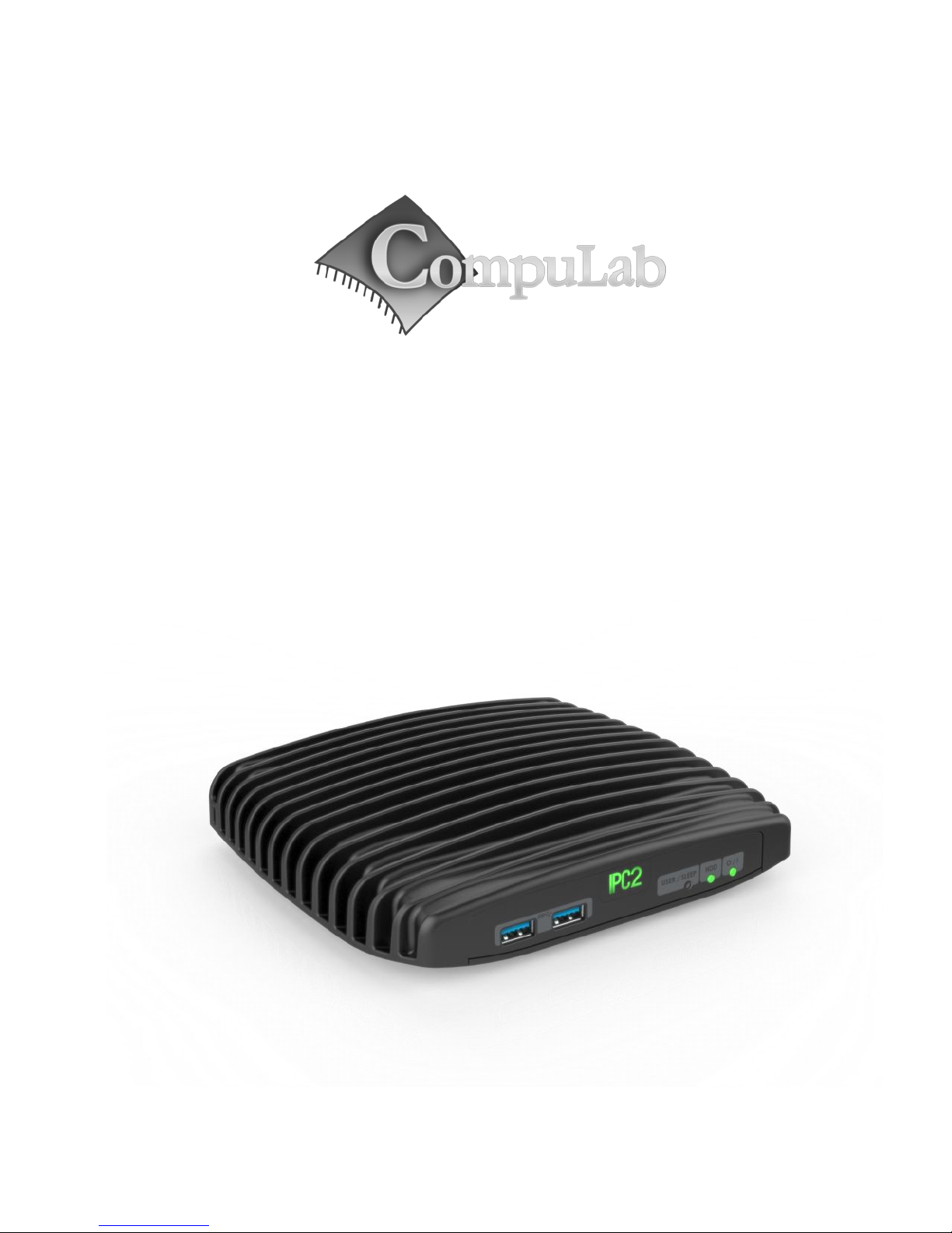
IPC2
Owner’s Manual
Page 2

2
IPC2 Owner’s Manual
February -2014
Introduction
Package contents
Hardware specifications
IPC2 features
Quick start guide
Connecting IPC2
Booting Linux
Booting Windows 7
Maintenance
Opening service door
Service bay
BIOS Setup Utility
Warranty and RMA
Warranty
RMA
Tips for saving power
General
In Operating System
For more information and to obtain the latest revision of this document, please visit
www.fit-pc.com
Page 3

3
Introduction
Package contents
1. IPC2 computer
2. Power supply: input 100-240VAC 50/60Hz, 60W output 12VDC 5A, DC plug lock,
3. Attachable Standard North-American and EU plugs AC cord. *
4. HDMI to DVI adapter
5. Audio 3.5mm to RCA cable
6. 2 WiFi antennas (in some models)
7. Mini-serial to DB9-female adapter cable
To use IPC2, you will need:
A display with DVI, HDMI or DisplayPort input + DVI, HDMI or DisplayPort cable
USB keyboard and mouse
* Local resellers may supply IPC2 with other AC cord types.
Hardware specifications
Processor
Type
Intel 4th Gen Core Celeron-2955U / i3-4010U / i5-4300U / i7-4600U
(Haswell)
Cores
64-bit dual core
Clock speed
1.4-2.1GHz (turbo boost up to 3.3GHz) (depends on CPU)
TDP
15W
Chipset
Mobile Intel 8 Series (Lynx Point) in MCP package
Memory
Supported
2x SO-DIMM 204-pin DDR3L SDRAM memory slots
Up to 16GB (2x 8GB) DDR3L-1600 (1.35V only)
Storage
Supported
1x SATA up to 6 Gbps (SATA 3.0) for internal 2.5” HDD/SSD
2x mSATA slot up to 6 Gbps (SATA 3.0)
Graphics
GPU
Intel HD 4400 Graphics
Triple display mode supported
Display Interface 1
HDMI 1.4a up to 4096 x 2304 @ 24 Hz
Display Interface 2
DisplayPort 1.2 up to 3200 x 2000 @ 60 Hz
Display Interface 3
HDMI 1.4a up to 4096 x 2304 @ 24 Hz
Audio
Codec
Realtek ALC888-VC2 HD audio codec
Audio Output
Analog stereo output
Digital 7.1+2 channels S/PDIF output
3.5mm jack
Audio Input
Analog stereo Microphone input
Digital S/PDIF input
3.5mm jack
Page 4

4
Networking
LAN
2x GbE LAN ports
LAN1: Intel I218 GbE PHY (MAC integrated into the chipset) (RJ-45)
LAN2: Intel I211 GbE controller (RJ-45)
Wireless
WLAN 802.11ac (2.4/5GHz dual band Intel 7260HMW)
Bluetooth 4.0
Connectivity
USB
4x USB 3.0
2x USB 2.0
Serial
3x Serial communication ports
COM0: Full RS232 via mini serial connector
COM1: 2-wire RS232 via mini serial connector
COM3: 2-wire RS232 via mini serial connector
SIM
1x micro SIM slot (6 pins)4
Special I/O
N/A
Expansion
Half-size mini-PCIe socket
Full-size mini-PCIe socket2
Advanced Technologies
vPRO
Yes (Intel vPRO Technology)5
AMT
Yes (Intel Active Management Technology)5
CPU Virtualization
Yes
Special Functionality
Auto-On
Wake-on-LAN
Wake-on-Timer
PXE Boot
Watchdog
Operating System
Supported
Windows 7/8, 32-bit and 64-bit
Linux 32-bit and 64-bit
Embedded OS
Operating Conditions
Input Voltage
Unregulated 10 – 15VDC input1
Power Consumption
6W – 24W
Operating Temperature
1. Commercial
HDD models: 0°C – 50°C
SSD models: 0°C – 70°C
2. Extended (TE)
SSD models only: -20°C – 70°C
3. Industrial (TI)
SSD models only: -40°C – 70°C
Enclosure
Material
Die Cast Aluminum
Cooling
Passive Cooling Fanless Design
Dimensions
19cm x 16cm x 4cm
Weight
1150gr
Package
Warranty
5 years3
Notes
1. Nominal input voltage: 12V
2. Shared with mSATA
3. For products purchased since 1-Jan-2013
4. For use with mini PCIe Cellular Modem module
5. Supported on LAN1 only
Page 5
5
IPC2 features
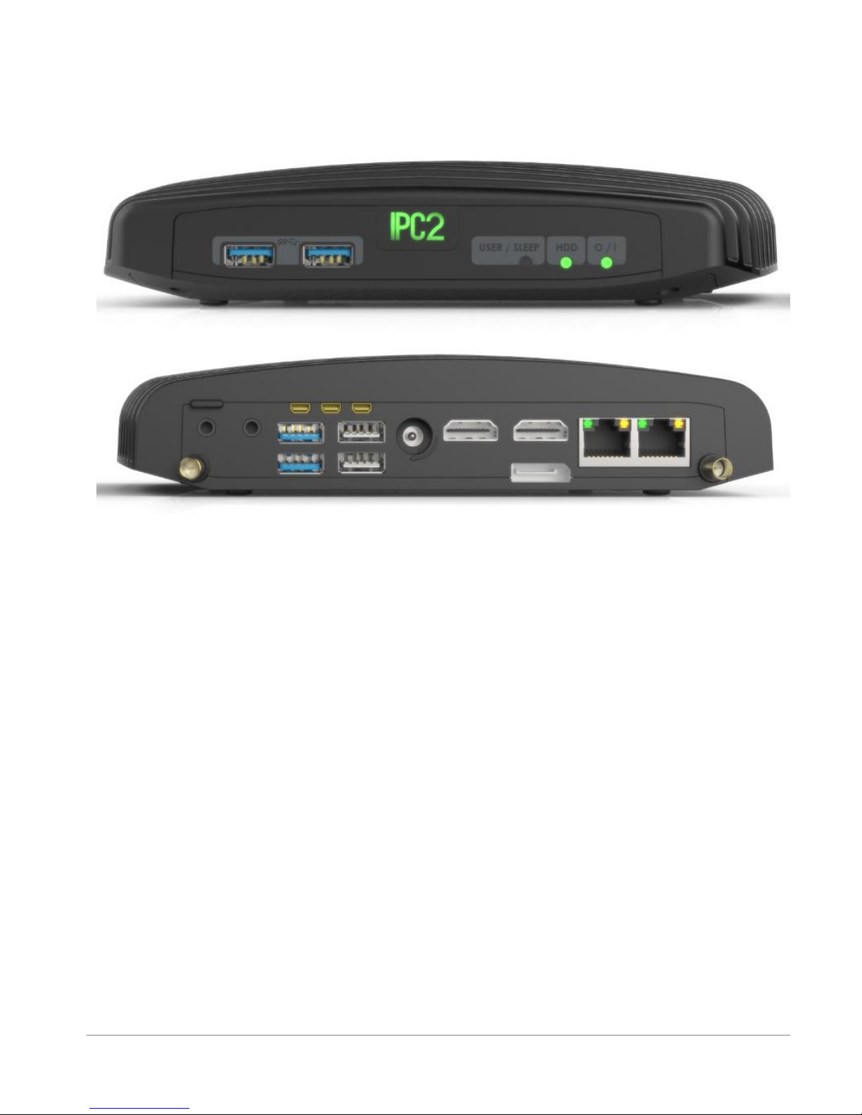
Front panel
The features of the front panel of IPC2 depend on specific FACE Module used and are documented
separately.
Power
IPC2 has a tactile power push-button. It is used for turning on/off the PC and for standby/resume when
supported by the operating system.
A push of at least 5 seconds will always turn off the IPC2.
Display
IPC2 has triple display interface with support for triple head.
1. 2x HDMI with audio support
2. 1x DisplayPort
To connect IPC2 to a DVI display, use the provided HDMI to DVI-D adapter. Use a DVI cable to connect the
adapter to the display.
Audio
There are 2 standard 3.5mm jacks on the back panel.
Right:
Stereo line-in using a standard 3.5mm plug
S/PDIF 7.1 in using provided cable
Left:
Stereo line-out using a standard 3.5mm plug
S/PDIF 7.1 out using provided cable
Page 6

6
LAN
IPC2 features two 10/100/1000BaseT Ethernet ports using standard RJ45 connectors. Use a standard
Ethernet cables to connect.
The connectors feature built-in LEDs that are lit when a connection is detected.
WLAN
2 WLAN antennas are supplied in models with integrated WiFi and should be screwed into the standard
SMA connectors.
USB
There are 2 USB 3.0 ports (5 Gbps) and 2 USB 2.0 ports on the back panel.
And additional 2 USB3.0 ports on the front panel.
All USB ports support current up to 1A.
Ports on the back are upside down – note when connecting USB plugs.
Serial port
Three RS232 mini-serial ports is located on the back panel.
Mini-serial to DB9 cable to connect to standard serial devices is supplied in the package.
Page 7
7
Quick start guide
Connecting IPC2
Turn off the display and connect it to the IPC2 HDMI connector (use the HDMI to DVI adapter if
needed).
Connect the USB keyboard and mouse to USB 2 connectors.
Plug the Ethernet cable into the Ethernet connector.
In IPC2 models with WiFi: Mount the WiFi Antennas on the SMA connector by turning it clockwise
repeatedly until the antenna holds firm.
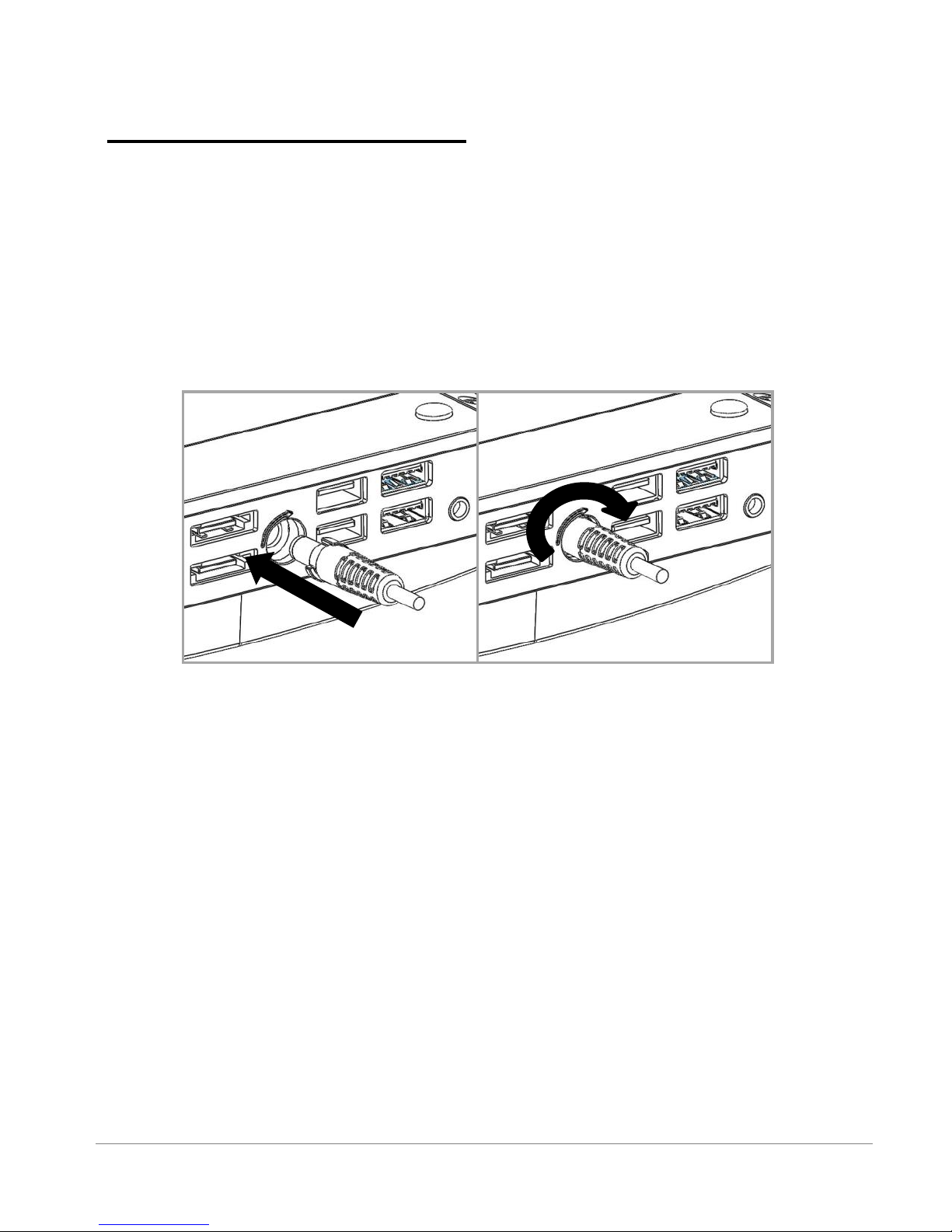
Insert the DC plug into the IPC2 DC-in jack. Rotate clockwise 90
0
to secure.
Plug the speakers into the line-out jack.
Connect the power supply to the AC cord and plug the cord into AC outlet. The front panel logo
should light up as the IPC2 boots.
Booting Linux
Linux loads automatically on power up. Upon boot you will be guided through the Linux Mint first-boot
setup procedure.
Booting Windows 7
Upon first power-up, you will be guided through the Windows Welcome procedure which is selfexplanatory. The Windows 7 serial number is printed on the Windows 7 label on the bottom of your IPC2.
Page 8
8
Maintenance
IPC2 requires no maintenance. You should not take the IPC2 apart other than opening the service door.
Taking IPC2 apart will void its warranty.
The following operations can be conducted by the user:
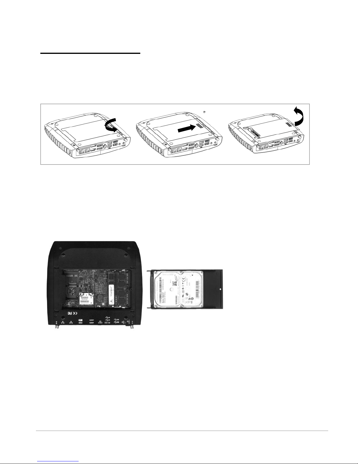
Opening service door
1. Unscrew marked Philips screw at the bottom to release service-door.
2. Slide out service-door until it stops – about 10 mm.
3. Service-door is now detached. Lift edge of service-door to completely remove.
Re-assemble in reverse order. Hard disk connects by sliding-in the service-door.
Service bay
The service-bay provides easy access to hard-disk, RAM, and mini-PCIe sockets incl. WLAN module.
Hard disk is 2.5” 7mm/9.5mm SATA. It is screwed to service door by 4 screws, 2 on each side. It is
recommended to use 5400 RPM hard disk or SSD. 7200 RPM or higher is not recommended due to higher
power consumption and risk of overheating.
RAM – use DDR3L-1333/1600 SO-DIMM modules.
Mini-PCIe – the half-size mini-PCIe is normally used for WLAN. If you remove the WLAN module make sure
to isolate the ends of antenna cables with some tape to avoid short-circuit. The full-size mini PCIe is
available for any use.
Page 9

9
BIOS Setup Utility
Entering BIOS Setup Utility
Turn off the IPC2.
Turn on while holding down the F2 key.
See http://www.fit-pc.com/wiki/index.php/Main_Page.
Warranty and RMA
Warranty
CompuLab guarantees products against defects in workmanship and material for a period of 60
months from the date of shipment.
Your sole remedy and CompuLab’s sole liability shall be for CompuLab, at its sole discretion, to
either repair or replace the defective product at no charge.
This warranty is void if the product has been altered or damaged by accident, misuse or abuse.
RMA
Keep the original package for shipping in case of hardware failure.
In case of HW failure of an IPC2 under warranty, please contact the seller of that IPC2.
Please provide the following required information:
IPC2 serial number
Name of purchaser
Address
Problem description
If the IPC2 was purchased directly from CompuLab, please email [email protected].
Tips for saving power
General
Working without a connected display automatically disables the graphics controller – saving
power.
Disconnect external USB devices when not in use.
In Operating System
Use power scheme as follows
Turn of monitor after several minutes not in use
Turn off hard disk after several minutes not in use
System standby after an hour not in use
Page 10

10
IPC2
Manufacturer: CompuLab Ltd.
This device complies with Part 15 of the
FCC Rules.
Operation is subject to the following two
conditions:
(1) This device may not cause harmful
interference, and
(2) This device must accept any
interference received, including
interference that may cause undesired
operation.
Statement
Changes or modifications to this
equipment not expressly approved by the
party responsible for compliance
(CompuLab Ltd.) could void the user’s
authority to operate the equipment.
Statement
NOTE: This equipment has been tested and found to
comply with the limits for a Class B digital device,
pursuant to part 15 of the FCC Rules. These limits are
designed to provide reasonable protection against
harmful interference in a residential installation. This
equipment generates, uses and can radiate radio
frequency energy and, if not installed and used in
accordance with the instructions, may cause harmful
interference to radio communications. However, there is
no guarantee that interference will not occur in a
particular installation. If this equipment does cause
harmful interference to radio or television reception,
which can be determined by turning the equipment off
and on, the user is encouraged to try to correct the
interference by one or more of the following measures:
-Reorient or relocate the receiving antenna.
-Increase the separation between the equipment and
receiver.
-Connect the equipment into an outlet on a circuit
different from that to which the receiver is connected.
-Consult the dealer or an experienced radio/TV technician
for help.
 Loading...