

Page 1
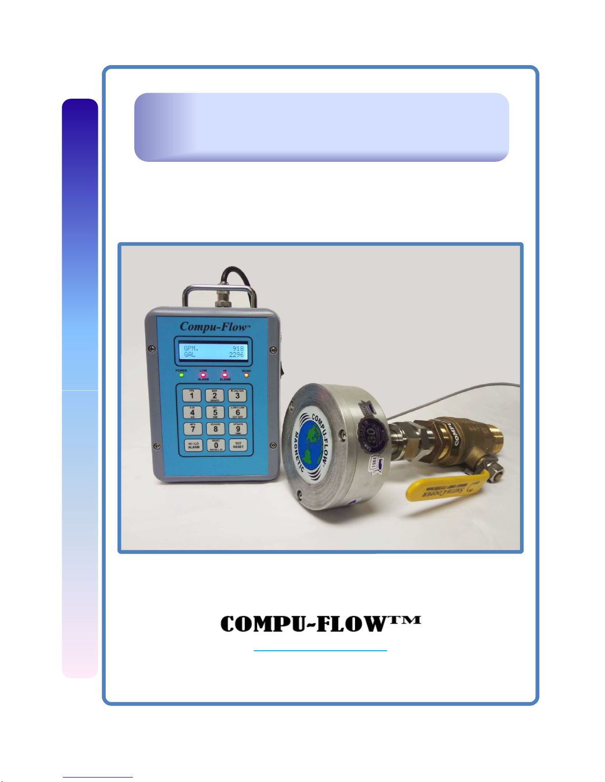
Compu-Flow™ EXM MAG
™
Electromagnetic Insertion Flow Meter
Compu-Flow
www.advancedflow.com
1-800-649-5331
Page 2
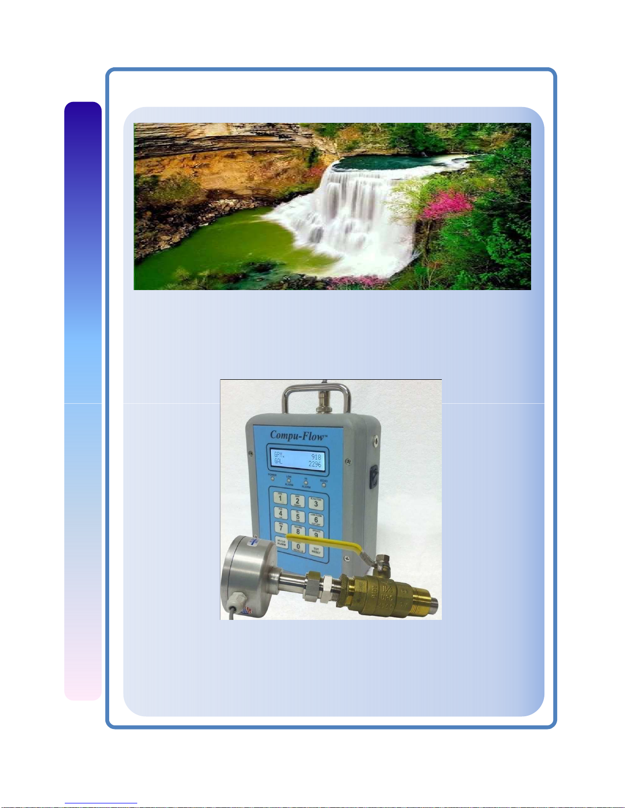
INTRODUCTION:
When you need a reliable flow meter the Compu-Flow™ is the right choice. We have been
manufacturing for the flow meter markets for the last 28 years.
Mag meters are the popular choice for closed pipe applications. The EXM model is the
most advanced design in the industry for Low Profile Single Point Insertion mag meters.
Compu-Flow™ EXM MAG
This style of flow meter is the practical choice for virtually all full pipe applications. The
EXM offers features often not found in even the most expensive spool piece models.
Rapid response time, simple installation and removal, rugged design, and unmatched
accuracy are just some of the advantages the EXM MAG offers. Combine this with our
user friendly display and competitive pricing and you have a winning combination.
2
Page 3
INTRODUCTION:
Compu-Flow™ EXM MAG
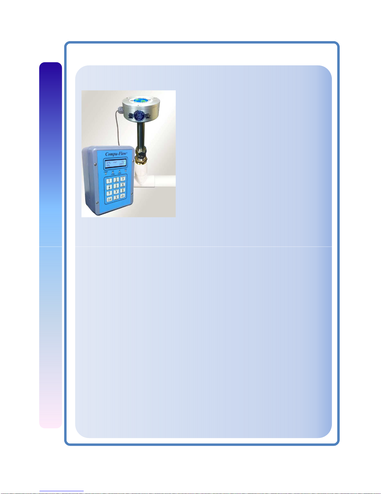
The basic kit of the C6 Compu-Flow™
Electromagnetic flow meter consists of a low
profile insertion sensor and a display control
panel.
A modular system of electronics can be attached
directly to the flow sensor or remotely mounted.
The meter provides full indication of rate and
total, plus 4-20 mA, HiLo Alarms, RS232, and
Batch Control.
The adapter of the EXM models, mates with a
standard female NPT fitting, and can be directly
threaded into ordinary saddles or threaded weld
fittings. The EXM115 thru EXM136 offer an
isolation valve, allowing hot-tap installation, or
installation and removal under pressure.
Compu
-
Flow
electromagnetic
flow
meters
work
under
the
Faraday
law
of
electromagnetic induction. They can be used to accurately measure the flow rate of
liquids which are electrical conducting, and mixed with liquids and solids. They are
widely used throughout industries of petroleum, pharmacology, papermaking,
electric power, environmental protection and so forth.
The main features of the control panel include:
• Smart LCD screen featuring high-resolution, 32 character, 2-line alphanumeric
providing rate and totalization simultaneously, in Metric or English units.
• Splash proof NEMA 4X case protects from moisture and caustics.
• Easy configuration for set up and operation with on-screen prompting, quick
scrolling menus, display panel keypad, and color coded LEDs.
• RS232 via DB9 PORT 9600 Baud.
• Batch Control, Isolated Output for Dry Contact Relay.
• Separate High and Low Alarm outputs for Dry Contact Relay with LED status.
• Data Logger 1 – 32 GB memory USB Flash Drive data transfer.
• Wireless Signal option from Sensors and/or Receiver (sensor singular).
• Optional signal cable lengths up to 5000 ft. No Tuning required.
3
Page 4

INTRODUCTION:
Compu-Flow™ EXM MAG
• Great accuracy even in turbulent flows.
• Wide pipe diameter range 2 – 72 inches.
• Maintenance-modular construction simplifying field service.
• Non-volatile Flash Memory for installed parameters 99 yrs.
Operating Conditions:
• Ambient temperature: 0°-180° F (-17° - 82° C).
• Fluid temperature: 32°-200° F (0° - 93° C).
• Submersibility: Water proof up to 200 ft.
• Pressure: Brass/SS = 200 psi (13.8 bar)
• PVC = 150 psi (10 bar) @ 75° F.
• Applicable Fluid: Electrically conducting liquid.
• Electrical conductivity: 20 Microsiemens / cm².
• Pipe Range: 2” –72” ID.
• Flow Range: 0.01 – 20.0 fps. (0.03 – 6.09 m/sec)
Technical Parameters:
• Housing: IP68 cast housing with modular electronics.
• R/T Back Lit LCD UFMC6 Display Std.
• Power range 10-24 VDC, no fuses to change. Carbon Arc auto resettable
circuit brakers,1 million cycle avg. life. Fast acting break and quick reset.
• Digital signal: 12VDC proportional to flow @ 60 Hz/fps, nom. 50/50 duty
cycle.
• Signal LED output 12 VDC @ 10 mA with full pipe and flow.
• Update time: Selectable 1-30 sec. at receiver.
• Fitting size: 1½” Male NPT (EXM110/136); 2” Male NPT Ball Valve.
• Auto averaging: 30 sec.
• Frequency Output: 60 Hz /fps.
• Bar Graph Flow/mA output LCD indicator.
• Pulse Output: Square wave pulse, isolated, 1200 Hz @ 20 fps.
Forward flow standard, reverse flow optional.
• Flow signal: 10 mA @ 12 VDC Green Wire.
• K factor Default: 60 Hz/fps. Adjustable 1-256.
• Empty pipe detection: Software defaults to zero flow.
• Voltage output 1-5 VDC proportional to flow selectable.
• Hi&Lo Limit Alarms user select output to solid state relays.
4
Page 5
Compu-Flow™ EXM MAG
Technical Parameters: (cont.)
• Communication: RS232 Receiver output DB9 / USB cable.
• Data Logger with USB memory and SD card platforms.
• Accuracy: 1% of full scale.
• Supply power: 12 VDC @ 300mA minimum.
• Housing material: Cast aluminum, powder-coated paint.
• Shaft/Fitting made of: 316 SS or Brass.
• Electrode Material: Hastelloy.
• Electrode cap material: Teflon, Mylar or Nylon.
• Valve assembly (EXM120-136): Bronze with SS ball valve.
• Nylon Tapered Ferrel Shaft Seal all models.
• Calibration accuracy: ± 1% of full scale.
• Reverse flow rate output with indicator signal. Optional.
• Noise immune circuitry, very stable, not ground loop sensitive.
• Nominal formula for insertion depth: 10% of pipe ID.
• Virtually unlimited cable length with no tuning required. Signal Cable 25ft std.
up to 1,000 ft w/o boost; 5,000 ft max.
• Simple 4 wire terminal connection with no tuning required.
• Digital signal output from the pipe. Unique stand alone sensor.
• Rugged construction. Quality components. SMT build format. Ultra reliable.
• Easily multiplexed to SCADA and PLC receivers.
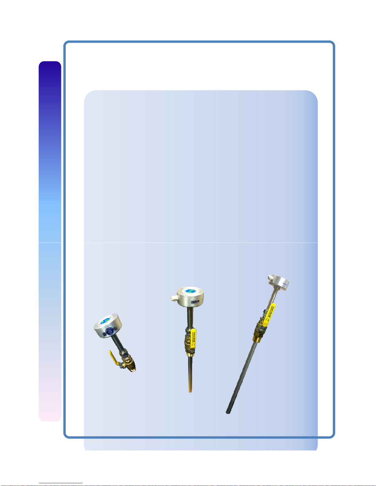
EXM110B
EXM124BBV
Custom Length
Special Model
EXM136BBV
5
Page 6
Compu-Flow™ EXM MAG
INSTALLATION:
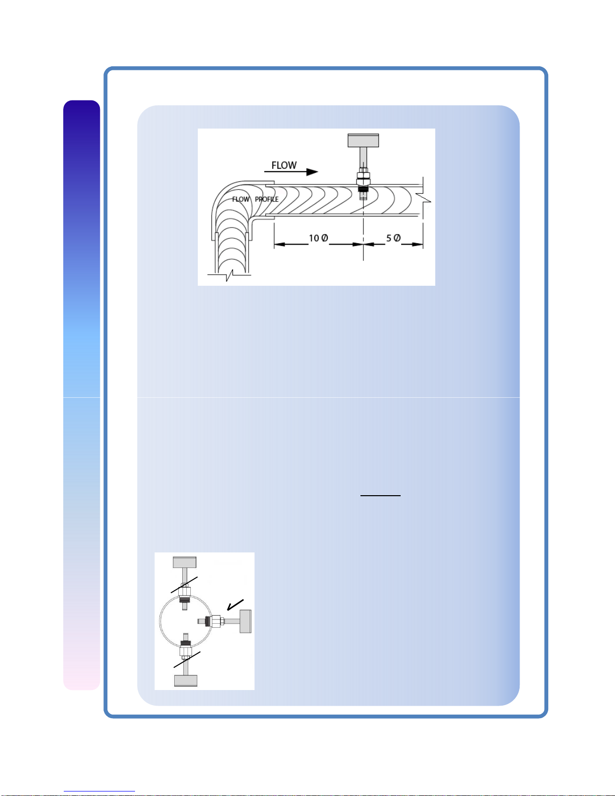
For best performance, the EXM sensor should be installed with at least ten
diameters of straight pipe upstream and five downstream. Certain extreme
situations such as partially-opened valves are particularly difficult and may
require more straight diameters upstream.
Chemical Injection or Fertigation. When any magmeter, by any
Position of the meter:
Vertical flow in upward direction is the
preferred installation orientation, since it
improves low-flow performance and avoids
problems with trapped air and sediment.
Bottom, top, and vertical pipe installations are
all acceptable if required by the piping layout.
manufacturer,
is
used
inachemical
injection
application
(including
fertigation), the chemical line must be placed downstream of the
magmeter OR far enough upstream for complete mixing to occur before
the fluid reaches the meter. When unmixed chemical or fertilizer alternates
with water passing through the meter, the rapid changes in conductivity
may cause sudden spikes and drops in the meter’s reading, resulting in
inaccurate measurement. The magmeter will restabilize, however, with a
steady flow of fluid of uniform conductivity. Caution!: In chemical injection
or fertigation applications, install chemical line downstream of magmeter,
or far enough upstream to allow complete mixing of fluids before the
meter.
6
Yes
No
No
Page 7
Compu-Flow™ EXM MAG
Caution!: These flow sensors are not recommended for installation
downstream of a boiler feedwater pump where installation fault may
expose the flow sensor to boiler pressure and temperature. Maximum
recommended temperature is 200°F.
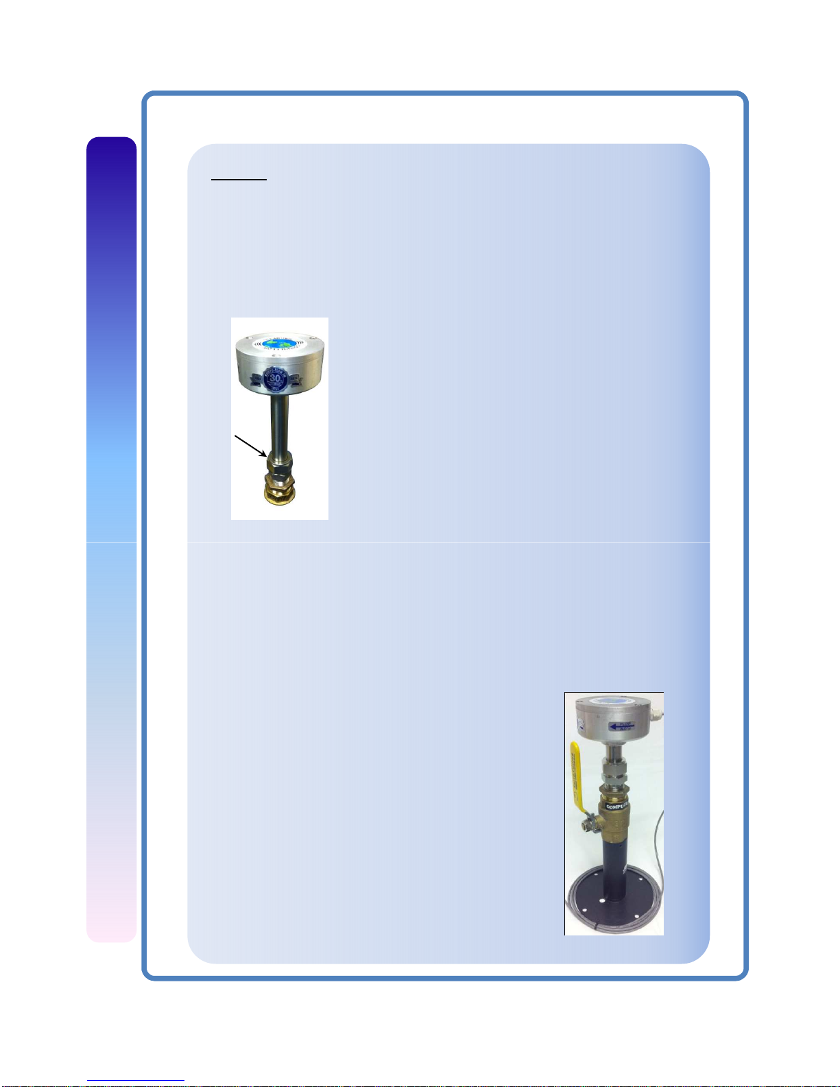
Fitting Installation. EXM adapters mate with a 11/2” female NPT pipe thread adapter fitting. Any
fitting that provides the matching NPT female
thread may be used. Installation procedure
compensates for fitting height differences. Cut a
minimum 1-3/4” hole in the pipe. If possible,
measure the wall thickness and write it down for
use in depth setting. Then install the threaded
fitting (saddle, weldolet, etc.) on the pipe.
INSTALLATION:
Installation of EXM 110-136:
Compression
Nut
Meter
Installation
.
Loosen
the
compression
nutsothat
the
adapter
slides
freely. Pull the meter fully upward and finger-tighten the compression nut.
Using a thread sealant, install the adapter in the pipe fitting. Do not
overtighten. Now loosen the compression nut, lower the meter to the
appropriate depth setting (see diagram and instructions that follow). Be
sure flow is in the direction of the arrow on the housing. Tighten
compression nut fully.
Installation of ‘Hot Tap’ EXM 115-136:
‘Hot tap’ EXM meters are designed so they can be
installed and serviced without depressurizing the
pipe.
Fitting Installation. The EXM 115 thru 136
adapters mate with a 2” FNPT threaded fitting for
compatibility with the 2” isolation valve. Any
fitting that provides matching NPT female thread
may be used. The installation procedure
compensates for differences in fitting height.
If initial installation is performed on an
unpressurized pipe, cut a minimum 1-3/4” hole in
the pipe.
7
Page 8
Compu-Flow™ EXM MAG
INSTALLATION:
Installation of (Hot Tap) EXM 110 thru 136: (cont.)
If possible, measure the wall thickness and write it down for use in depth
setting. Then install the threaded fitting (saddle, weldolet, etc.) on the pipe.
If it is necessary to do the initial installation under pressure, any standard
hot tap drilling machine with 2” NPT adapter, such as a Transmate or a
Mueller, can be used. Ordinarily, it is not necessary to use an installation
tool, due to the small diameter tube the meter can be installed by hand at
all but the highest pressures.
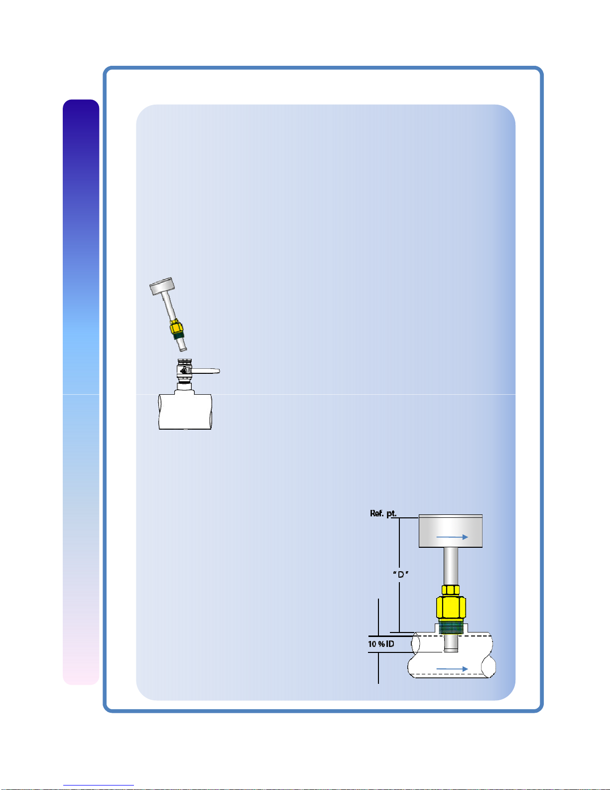
Meter Installation. Remove the sensor unit from the
valve assembly. Using a thread sealant, install the valve
assembly on the pipe fitting. If the initial installation is a
pressure (“hot”) tap, remove the 1-1/2” x 2” adapter
bushing at the back of the valve. Thread the tapping
machine on, open the valve, and tap using a minimum of
1-3/4” or maximum 1-7/8” cutter. After retracting the
machine and closing the valve, reinstall the flow sensor.
When the sensor is secure, open the valve and adjust
depth
setting
(see
diagram
and
instructions
that
follow)
.
Be sure flow is in the direction of the arrow on the
housing. Tighten fitting and compression nut fully.
Depth Setting. It is important for accuracy
that the sensor be inserted to the correct
depth into the pipe.
1. Take dimension from reference point (joint
in the housing) up to the tip of sensor.
2. From this whole dimension, subtract
10% of pipe I.D., and pipe thickness, to
obtain dimension “D”.
3. Measuring from the outside of the pipe to
the joint in the housing, as shown in the
diagram, adjust the sensor to Dimension D
and hand-tighten compression nut.
3. Align the conduit housing with the
centerline of the pipe. Be sure the arrow
on the housing points in the direction
of flow.
8
Flow
Flow
Page 9

Compu-Flow™ EXM MAG
INSTALLATION:
Depth setting: (cont.)
4. Check Dimension D one more time.
5. Tighten the compression nut fully.
Caution!. Never attempt to remove a flow sensor when there is pressure in
the pipe unless it is specifically designed for hot tap installation and removal.
Loosen the compression nut slowly to release any trapped pressure. If fluid
sprays out when removing the sensor, stop turning and depressurize the
pipe. Failure to do so could result in the sensor being thrown from the pipe,
resulting in damage or serious injury.
NOMINAL PIPE SIZE
3" 4" 6" 8" 10" 12" 14" 16" 18" 20" 24" 30" 36"
PVC/Steel
Sch.40
0.216 0.237 0.280 0.322 0.365 0.406 0.438 0.500 0.562 0.593 0.687
PVC/Steel
Sch.80
0.300 0.337 0.432 0.500 0.593 0.687 0.750 0.843 0.937 1.031 1.218
Table 1: Pipe Wall Thickness
Sch.80
Stainless
Steel(10S)
0.120 0.120 0.134 0.148 0.165 0.180 0.188 0.188 0.188 0.218 0.250 0.312 0.312
Stainless
Steel(40S)
0.216 0.237 0.280 0.322 0.365 0.375 0.375 0.375 0.375 0.375 0.375 0.375 0.375
Copper
Tubing
(Type L)
0.090 0.110 0.140 0.200 0.250 0.280
Copper
Tubing
(Type k)
0.109 0.134 0.192 0.271 0.338 0.405
Brass Pipe 0.219 0.250 0.250 0.312 0.365 0.375
Duct. Iron
(Class 52)
0.280 0.290 0.310 0.330 0.350 0.370 0.390 0.400 0.410 0.420 0.440 0.470 0.530
9
Page 10
Compu-Flow™ EXM MAG
INSTALLATION:
Minimum Straight Pipe Length Requirements
The meter´s accuracy is affected by disturbances such as pumps, elbows,
tees, valves, etc., in the flow stream. Install the meter in a straight run of
pipe as far as possible from any disturbances. The distance required for
accuracy depend on the type of disturbance.
Type of disturbance
Straight Lengths of Pipe Required
Upstream from transducers Downstream from transducers
Flange 5 X Nominal Pipe Size 5 X Nominal Pipe Size
Reducer 7 X Nominal Pipe Size 5 X Nominal Pipe Size
90° Elbow 10 X Nominal Pipe Size 5 X Nominal Pipe Size
Two 90° Elbows - 1 Direction 15 X Nominal Pipe Size 5 X Nominal Pipe Size
Two 90° Elbows - 2 Directions 20 X Nominal Pipe Size 5 X Nominal Pipe Size
Gate valve or Pump 25 X Nominal Pipe Size 5 X Nominal Pipe Size
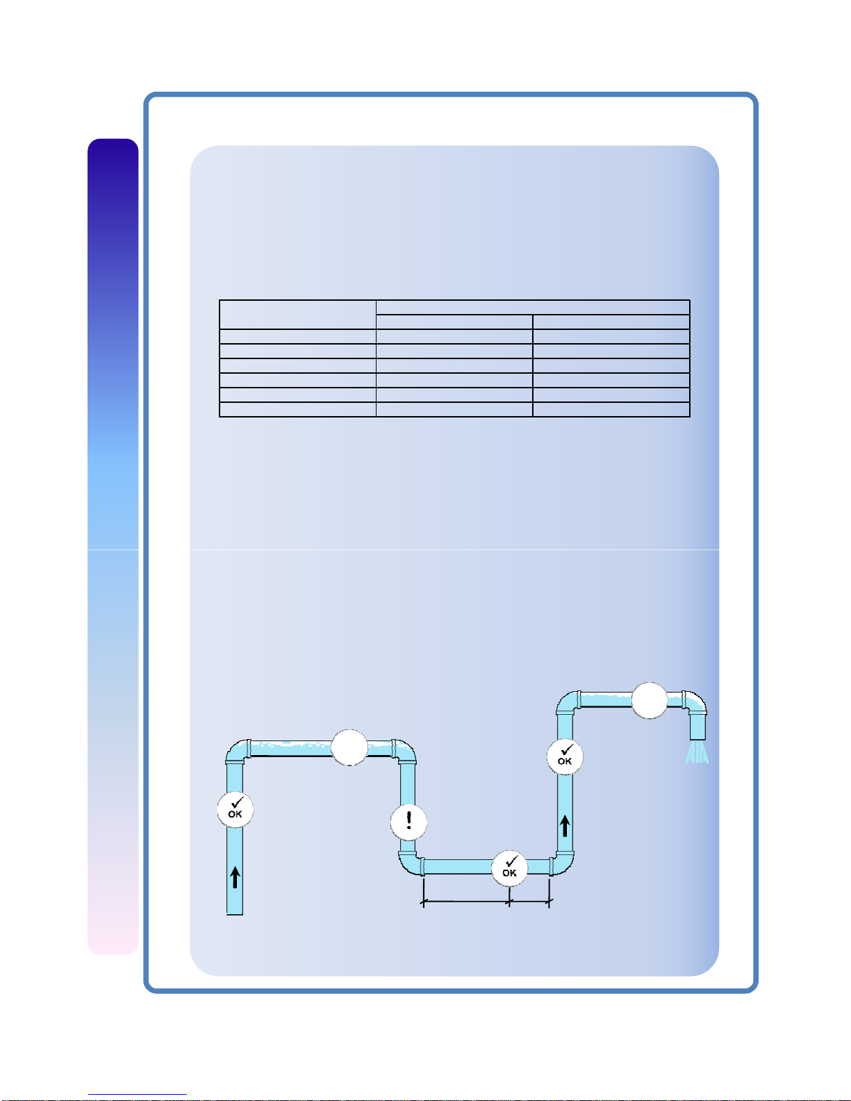
• The meter can be mounted on horizontal or vertical runs of pipe.
• Avoid mounting on vertical down flows when possible.
• Mounting on the sides (3 o´clock and 9 o´clock) position on
horizontal pipe is recommended.
• Mounting anywhere around the diameter of vertical pipe is
NO
NO
Air could be trapped
Pipe must be full
Down flows
must have
back pressure
>= 10Ø
>= 5Ø
acceptable,
however,
the
pipe
must
be
completely
fulloffluid
at all times.
• Back pressure is required on downward flows to ensure a full pipe.
• See the minimum straight length of pipe requirement chart above.
• The meter can accurately measure flow from either direction.
Best recommended () spots to install flow meters:
10
Page 11
Compu-Flow™ EXM MAG
ELECTRICAL CONNNECTIONS:
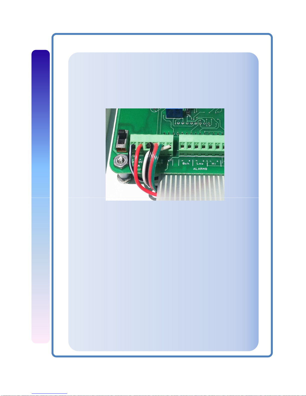
Transducer wiring:
If your electromagnetic sensor is not yet connected to the electronics
control panel, open the panel, and use the next figure as a guide to make
the proper wiring for the 4 transducer cables: Black (-12VDC), Red (+12VDC),
Green (Echo), White (Signal).
VDC
B
R
G W
-
+
General Electrical Guidelines:
• Whenever possible avoid running control cables in the same
conduit with or bundled with AC power.
• Using shielded cable, be sure to connect shield to ground at
power supply end of the cable.
• Avoid routing flow sensor cables in close proximity to a
variable frequency drive when possible.
• Recommended power and output wiring is shielded twisted pair
18-22 AWG control cable.
• Recommended voltage is 12-24 Vdc. Note that unregulated
power supplies can vary from nameplate voltage by a
considerable amount, especially with AC line voltage fluctuation.
Therefore 24V power supplies must be regulated.
Output: The EXM sensor output is a 0-5V square wave digital pulse train
proportional to flow @ 60Hz/fps .
Note: The EXM power requirement is 190mA@12VDC .
11
Page 12
Compu-Flow™ EXM MAG
ELECTRICAL CONNNECTIONS:
Grounding Guidelines:
For best results, use a good quality earth ground, such as metallic water
piping or a driven ground, to ensure a good connection to earth ground and
good noise suppression.
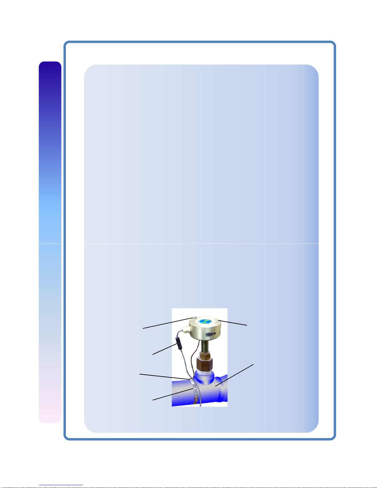
If the flow sensor is installed in metallic piping, for optimum connection
clamp wire to the piping a short distance to one side of the flow sensor
using an electrical grounding clamp. Connect the wire to the earth ground
and to one of the housing screws. For Non-Metallic Pipe: Connect one to the
housing screws by wire to a good earth ground, such as metallic water
piping or a rod driven into the ground.
EXM meters are usually unaffected by moderate levels of electrical noise. In
some applications performance may be improved by taking the following
steps:
• Use shielded twisted pair cable (Belden 8723 or equivalent above
ground or Alpha 35482 or equivalent burial).
• Clamp a ferrite bead (Steward 28A2029-OAO or equivalent) on meter
signal/power
wire
within
3/4”of
the
meter
strain
relief
(tape
or
tie
wrap
in place if necessary). See diagram below.
• IMPORTANT - Connect the cable shield ground wire to ground, ONLY at
power supply end of cable.
Earth Ground
Metallic Pipe
Grounding Clamp
Place Ferrite
Bead Here
Housing Screw
Grounding diagram:
Earth Ground
12
Page 13

Compu-Flow™ EXM MAG
TROUBLESHOOTING
Problem: No pulse output
Probable cause:
•Unit not grounded
•Below minimum flow cutoff
•Flow reversed
•Output connections reversed
•Pipe not full
•Excessive electrical noise
•No power
•Power reversed
•Fluid conductivity <20 microSiemens/cm
Try:
•Connect to earth ground
•Check the Presence of Flow
•Note flow direction arrow, reverse direction to meter
•Change output connections
•Check plumbing
•Check for proper electrical wiring
•Check for power across power input terminals
•Reverse connections
•Select another flow meter
Problem: Output pulses incorrect
Probable cause:
•Missing or incorrect ground wire
Try:
•Check for proper ground
•
Incorrect depth setting
•Fluid conductivity <20 microSiemens/cm
•Empty pipe
•Not enough straight pipe
•Excessive electrical noise
•
Check depth setting
page
•Select another flow meter
•Check for full pipe or install meter in the vertical position
•Check for air pockets or turbulence. Refer to
installation page
•Check for proper electrical wiring
Problem: Jumpy reading
Probable cause:
•Rapidly changing conductivity (in chemical
injection or fertigation applications)
Try:
•Install chemical injection line downstream of magmeter
(or far enough upstream to allow complete mixing of
fluids before meter)
13
Page 14
Compu-Flow™ EXM MAG
PROGRAMMING
To Operate Your Flow Meter for the First Time:
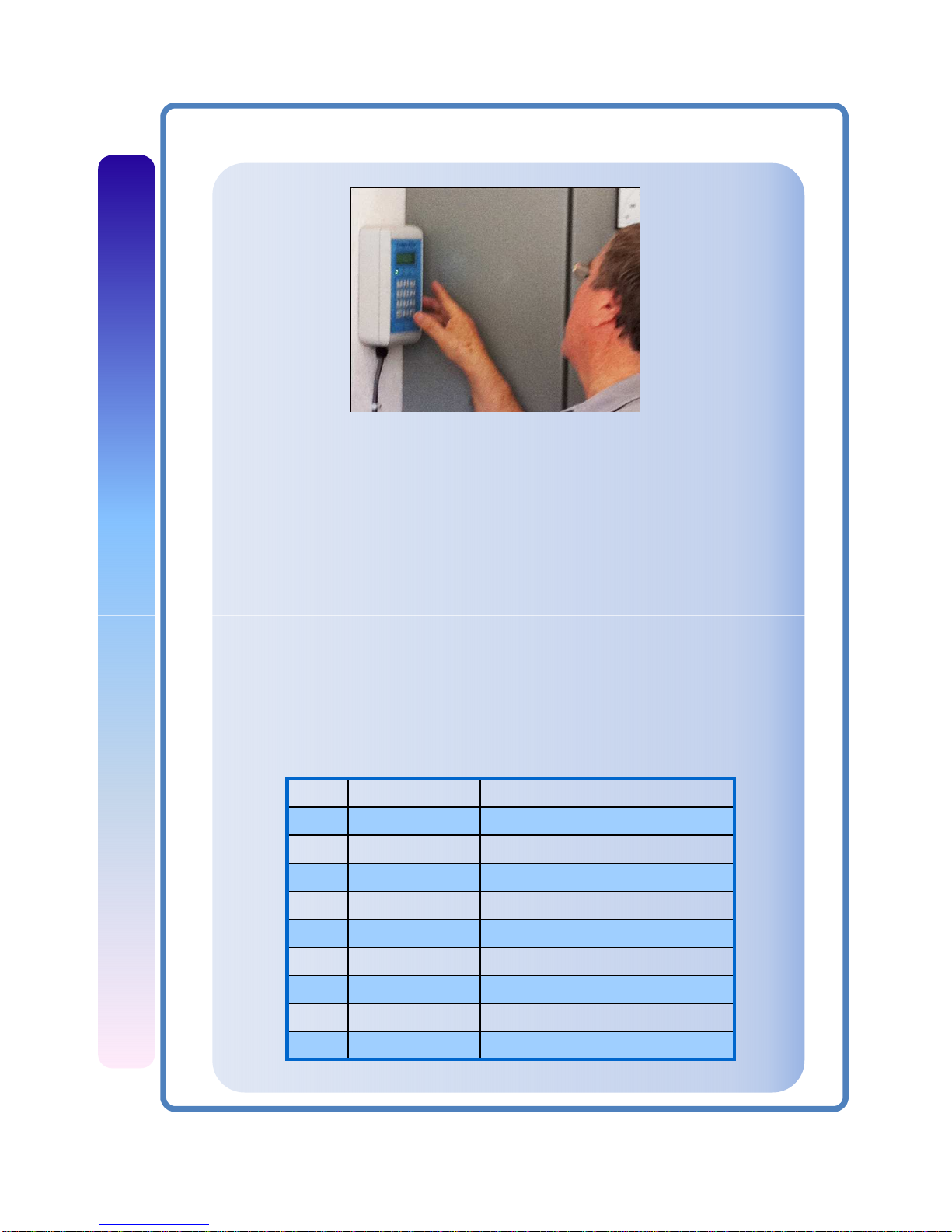
1. Complete all the steps in “Installation” pages.
2. Turn on power and observe the display panel LCD. The display will show the
model name and number of the unit.
3. Following the prompts presented by the display panel LCD, and making your
entries using the keypad, configure your unit for operation for English or
Metric
.
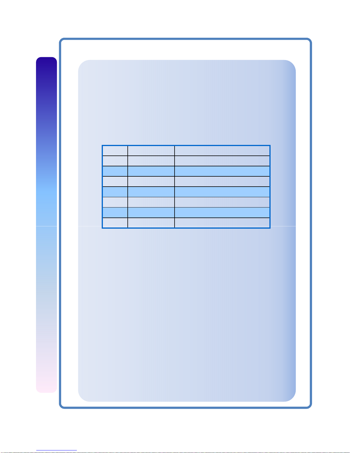
□ The LCD screen displays SELECT RATE. Select the unit of measure for
rate display: All rate selections may be displayed in seconds, minutes,
hours, days. Time elements: (1=Sec 2=Min 3=Hr 4=Day)
Table 2. Rate selection - English
Key Selection Definition
1 FPS Feet per second
2 GAL Gallon
3 CF Cubic feet
4 MG Million Gallons
5 AF Acre Feet
6 BL Barrel 42 gal
7 MPS Meters per second
8 LT Liter
9 CM Cubic meter
14
Page 15
Compu-Flow™ EXM MAG
PROGRAMMING
If you select FPS, the flow meter will automatically begin measuring flow in
feet per second. If you select keys 1 through 6, the LCD screen will ask that
you enter your pipe ID in inches. If you select keys 7 through 9, the LCD
screen will ask that you enter your pipe ID in millimeters.
After you enter your rate time element, the LCD screen will then display
SELECT TOTALIZER. Select the unit of measure for totalizer display:
Table 3. Totalizer selection
Key Selection Definition
1 GAL Gallons
2 CF Cubic feet
3 MG Millions of gallons
4 AF Acre feet
5 BL Barrels 42 gal
6 LT Liters
7 CM Cubic meters
Your EXM flow meter is now configured to measure the flow parameters you
have set. After you set the flow reading parameters you need for your
system, you can secure these settings so they are saved in the event of
power loss to the electronics enclosure.
Note: To clear the rate and totalizer parameters you have set, select “0”
reset or switch the power off using the on/ off switch on the display panel.
Until settings are saved using Key # 8, “Secure On”, the security switch,
turning off power clears all previously set parameters. When you turn on
power again, the LCD screen will prompt you to restart programming.
After you enter your totalizer selection, the LCD screen will then display
Enter Pipe ID. If you select keys 1 through 5, the LCD screen will ask that you
enter your pipe ID in inches. If you select keys 6 through 7, the LCD screen
will ask that you enter your pipe ID in millimeters.
15
Page 16
Compu-Flow™ EXM MAG
PROGRAMMING
To Save Your Programmed Flow Reading Settings Using the Secure Function:
1. Complete setting the flow reading parameters.
2. Press and hold key # 8 for 5 seconds until “Secure On” appears on the
LCD display.
Note: If you need to change your programming, press and hold key # 8
“Secure” until “Secure Off” appears on the LCD display.
If you wish to further customize your flow meter system for operation in
your process, continue on to “Advanced Configuration Options”.
Advanced Configuration Options
The display panel keypad has a secondary menu for advanced configuration
options (the keypad toggle menu). You may want to use this menu to set 4-
20mA analog output, set up bar graph, select HI/LO alarm set points, and
configure batch control. To access the secondary menu, press appropriate
key until the display changes. To exit, press the key again.
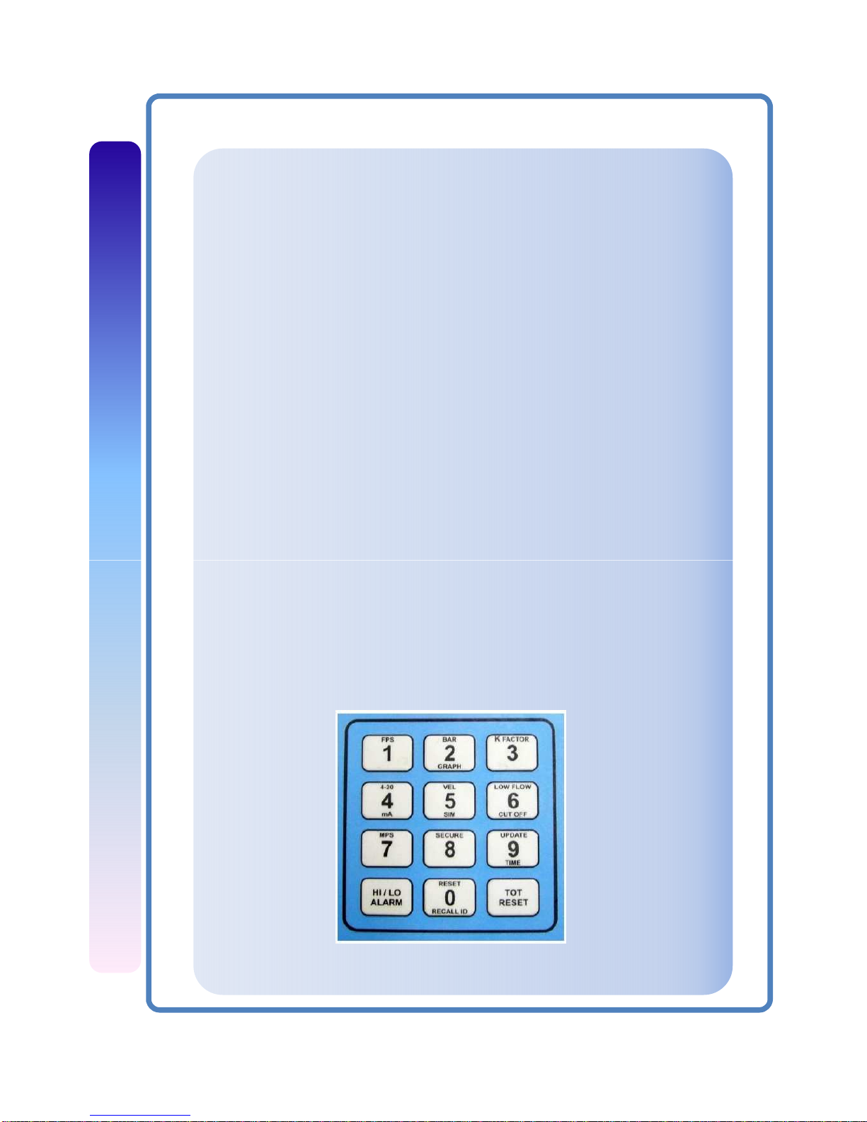
• Figure 1 provides a visual representation of the toggle menu.
• Table 4 lists the advanced configuration options accessible from the
display panel keypad.
Figure 1. Display unit keypad
Bar graph
K factor reset (1 to 256)FPS/PWR clear
4-20 mA
MPS/PWR clear
High / Low alarm
Low flow cutoff
(Maximum = 2.5 fps)
Set update time
(1sec,10sec,auto av.)
Totalizer reset
16
Page 17
Compu-Flow™ EXM MAG
PROGRAMMING
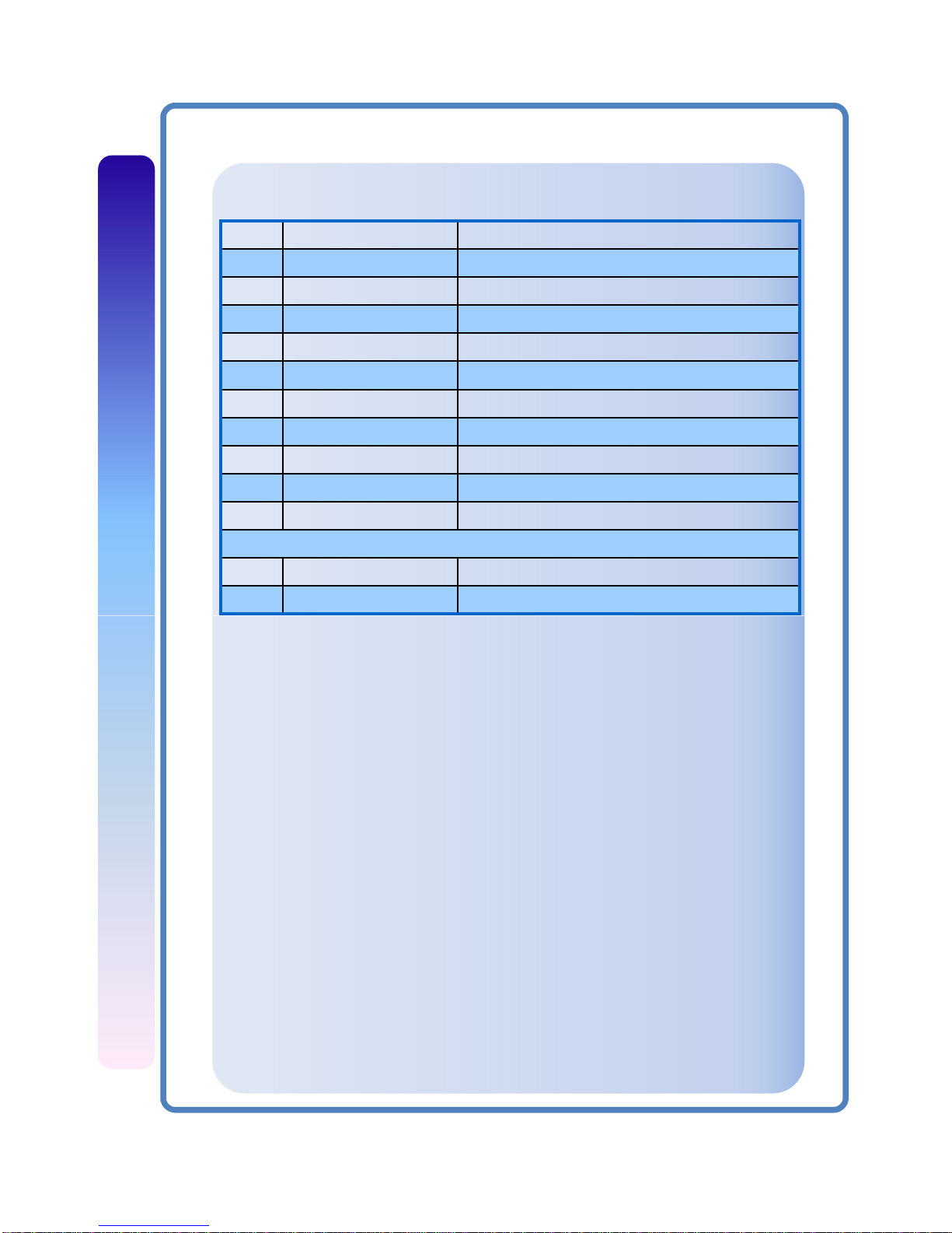
Key Selection Functional Specifications
1 FPS Feet per second/ clear pwr
2 Bar Graph Analog 16 pt bar graph (n/a with batch)
3 K Factor Select K factor while running
4 4-20 mA Set up 4-20 mA analog output
5 Vel Sim Velocity Simulator for systems test
6 Low Flow Cut Off Set low flow cut off (maximum = 2.5 fps)
7 MPS Meters per second/ clear pwr
8 Secure Secure parameters On / Off
9 Update Time Select update time: 1, 2, or 3
0 Reset / Recall Pipe ID Recall pipe ID/ configure batch/ system reset
HI / LO ALARM Set up HI/LO limit alarms/ reset cursor
TOT RESET Reset totalizer while running/ reset cursor
Table 4. Keyboard Toggle Menu
The default setting for secondary keyboard functions is feet per second (fps),
or meters per second (mps) if the flow meter is configured for metric units.
Once the flow meter is operational and you wish to activate the analog bar
graph, 4-20 mA output, batch control, high or low alarm, or low flow cut-off
options, consult advanced parameter setting.
Before Setting Advanced Parameters
Sample parameter setting:
You have a velocity of 5 fps and you would like the 4-20 mA output to be 12
mA or 50% of scale. Push and hold the MA/4 key until the screen changes
and then release the key. Enter a scale value of 10 fps via the keypad. The
screen will automatically return the display to volumetric indication. The 4-
20 mA output will read 12 mA at the terminal strip located on the right side
of the main electronics circuit board. You may check your 4-20mA output
setting via the bar graph.
17
Page 18

Compu-Flow™ EXM MAG
PROGRAMMING
Note: Never adjust any of the potentiometers on the main processor board.
These settings are to be performed by authorized personnel only.
SETTING ADVANCED PARAMETERS
Bar Graph
To Set the Analog Bar Graph of Flow Rate: (n/a with batch)
1. Press the Bar Graph/2 key. Enter the desired full-scale flow rate
in the indicated engineering unit.
2. To return to the rate and totalizer flow reading, press the
Graph/2 key again.
3. To return to the graph, press the Graph/2 key again and select OK.
This section explains how to set advanced parameters using the keyboard on
the front panel of the unit.
Batch Control
K Factor (Correction Factor)
The default K Factor on the flow meter is set at 60 hZ/ fps for EXM Sensors.
For nearly all applications, this default K Factor setting should be adequate.
There are only a few circumstances that might merit adjusting the default K
Factor setting on your Electromagnetic flow meter.
1. To configure batch control press “0” key and select Batch.
2. Select Enable and choose 1=Pulse, 2=Batch.
3. Select Batch volume in preselected engineering units.
Analog Output:
To Set the Analog Output:
1. Press the MA/4 key Enter the full scale preselected
engineering unit.
2. After the output level has been set, the LCD screen will
return to the rate and totalizer flow reading.
18
Page 19

Compu-Flow™ EXM MAG
PROGRAMMING
Low Flow Cutoff
To Set the Low Flow Cutoff:
1. Press the FPS/1 or MPS/7 key to obtain the current reading in feet
per second or meters per second. Press the key again to return to
the flow reading parameters previously shown.
2. Press the LFC/6 key. Enter the cutoff in feet per second or meters
per second. If you enter a parameter that is too high, the LCD
screen will display the maximum allowable cutoff setting and then
will return to the prompt for cutoff in feet per second.
Meters per Second/ Power Clear
3. After the low flow cutoff is set, the LCD screen will return to the rate
and totalizer flow reading.
To Read Meters Per Second:
1. Press the MPS/7 key. The LCD will show the flow reading in meters
per second on the upper line of the LCD screen, replacing the rate
parameter previously on the screen. The totalizer reading remains
the same parameter.
2. To return to the previous flow rate, press the MPS/7 key again.
Update Time
To Set Update Time:
1. Press the UT/9 key. To enter the selection screen.
1 = 1 sec 2 = 10 sec 3 = auto; “Auto” mode will update every
second when the velocity change is >5%. When the flow stabilizes
to < 5% change, the update time resets to a 10 second running average.
2. Enter the update time in 1 second, 10 seconds , or Auto.
3. After the update time is set, the LCD screen will return to the rate
and totalizer flow reading.
19
Page 20

Compu-Flow™ EXM MAG
PROGRAMMING
Hi/Low Alarms
Totalizer Reset
To Set the High/ Low Alarms:
1. Press the HI/LO ALARM key. Select Hi, Lo, or Both.
You may change the alarms one at a time without
affecting anything else.
2. Next enter the high limit alarm in your preselected
engineering unit.
3. Now enter the low limit alarm in your preselected
engineering unit.
4. After the high and low alarm parameters are set, the LCD
screen will return to the rate and totalizer flow reading.
To Reset the Totalizer While the Unit is Running:
1. Press the TOT RESET key. The totalizer reading will return to zero.
2. The meter will begin taking totalizer readings from zero.
The rate reading remains unchanged.
20
Page 21
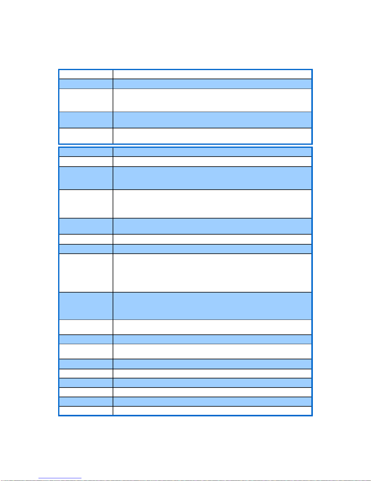
Table 5. Functional specifications
Description Specification
Alarm output
AC: Separate Power module required for relay/ output Alarms & Batch
RS232 output
RS232 via DB9 & USB ports
9300 baud rate
Terminal Emulation Software (HyperTerminal for Windows/ ZTerm for Mac)
Data Logger output
1-32 GB USB Flash drive
USB board mount or remote cable
Power failure backup
Allows the electronics assembly to retain all parameter information
and current totalizer value for 99 yrs
Standard interface Specification
LCD display
2-line, 16 characters per line, high resolution, backlit
LED indicators
· Yellow: Echo signal received
· Red: High alarm or low alarm activated
· Green: Power available
Keypad
12 keys, tactile feedback
Note: Keypad lockout via front panel keyboard; see “To Save Your Programmed Flow
Reading Settings:” on page 16 and figure 1
Display panel
Rate selection, totalizer selection, K factor selection, analog output, low flow cutoff,
update time (damping), high/ low alarm, fps, or mps selection, totalizer reset, etc
Output setting function
4-20mA output scaling (from keypad) in selected engineering units
Alarm setting function
High and low alarms set points (entered in engineering units)
Rate indication
4-digit LCD, velocity or volume (user selectable)
English units: feet per second (fps), gallons (Gal), cubic feet (CF), and million gallons
(MG), SMHD
Metric units: meters (M), liters (LT), and cubic meters (CM), SMHD
Note: Gallons refers to U.S. gallons, BBL=42gallon
SMHD= Seconds, Minutes, Hours, Days
Totalizer indication
12-digit LCD
English units: gallons, cubic feet, acre feet, barrels, and millions of gallons
Metric units: liters and cubic meters
Note: Gallons refers to U.S. gallons. BBL=42gallon
Update time (damping)
Entered from keypad
1sec – 10sec – Auto Running Avg (75%=1sec)
Low flow cutoff
0 fps to 2.5 fps (0 mps to 0.76 mps), entered from keypad
K factor
A value of 1 to 256, entered from keypad depending upon sensor type. The default is
60 Hz (correction factor) for version C6 EXM sensor
Totalizer reset
Totalizer reset can be manually reset to zero from keypad
Key “#” function
Reset flashing cursor
“0” Key function
Resume- Reset ; Pipe ID- Batch
“8” Key function
Secure On/Secure Off
“5” Key test function
Test velocity simulator on/off
“2” Key function
Setup 16 point Bar Graph tracks 4/20mA output (n/a with Batch)
21
 Loading...