

Page 1
Compsee, Inc.
Apex III Apex IV
Technical Reference
Manual
Second Edition
A Subsidiary of McRae Industries, Inc.
Page 2

This Page Intentionally Left Blank
Page 3

PORTABLE DATA
COLLECTION TERMINAL
TECHNICAL
REFERENCE MANUAL
SECOND EDITIONSECOND EDITION
Compsee, Inc.
A Subsidiary of McRae
Industries, Inc.
Page 4

Copyright Acknowledgments:
All terms and names mentioned within this publication that are known
to be registered trademarks and/or service marks have been
appropriately designated. Due to today's changing corporate
environment, Compsee, Inc. cannot attest to the accuracy of all of this
information. Use of a specific term in this publication should not be
regarded as affecting the validity of any trademark or service mark
known to exist.
HyperTerminal is a registered trademark of Hilgraeve, Inc.
Lenmar is a registered trademark of Lenmar Enterprises, Inc.
PhoenixPICO® BIOS and PicoCard are trademarks of Phoenix
Corporation.
PowerBASIC is a registered trademark of PowerBASIC, Inc.
PROCOMMPLUS is a registered trademark of SYMANTEC
Corporation.
ROM-DOS is a registered trademark of Datalight, Inc.
Borland is a registered trademark of Borland Software Coproration.
Microsoft, Windows, and MS-DOSare registered trademarks of
Microsoft Corporation.
COMPSEE, INC. 2002, All Rights Reserved
All parts of this manual, including illustrations and
specifications are the property of Compsee, Inc. The
information contained herein may not be reproduced in whole
or in part for
any reason without express written authorization
from Compsee, Inc.
The material contained within this manual is for informational
purposes only and subject to change without notice.
COMPSEE, INC., Apex III, and Apex IV
are authorized
trademarks of Compsee, Inc., Mt. Gilead, NC 27306
Manual Number COAM30002, Rev. 2.00
Page 5

Apex PDT Technical Reference Manual Table Of Contents
COAM30002 Rev. 2.00 8/13/02 i
TABLE OF CONTENTS
1 GENERAL INFORMATION ...................................1-1
Introduction..............................................................1-1
How To Use This Manual ........................................1-1
Supported Symbologies............................................1-2
2 SAFETY...................................................................2-1
Apex PDT Laser Safety ............................................2-1
Standard and Very High Density.........................2-1
Long Range And Advanced Long Range Laser ..2-3
Battery Pack Notes And Safety................................2-5
Product Conformity..................................................2-6
3 HARDWARE CONFIGURATION.........................3-1
Associated Pinouts....................................................3-1
DIP Switch Configuration........................................3-3
System Architecture .................................................3-4
Apex PDT Memory Map..........................................3-5
Display......................................................................3-6
Font Height Adjustments.....................................3-7
Font Display Illustrations ....................................3-8
Supported Character Sets ....................................3-8
Standard ASCII Characters................................3-9
Extended ASCII Characters............................. 3-10
Latin-1 Character Set ....................................... 3-11
Keyboard ................................................................3-12
Apex Specific ROM BIOS Extensions...................3-14
Extension Summary..........................................3-14
Detailed BIOS Interrupt Information................3-15
BIOS Interrupt 10h – Video Functions.............. 3-15
Set 8 High Font.........................................3-15
Set 16 High Font.......................................3-15
BIOS Interrupt 15h - System............................ 3-16
Get Beeper Volume ..................................3-16
Set Beeper Volume...................................3-16
Page 6

Apex PDT Technical Reference Manual Table Of Contents
COAM30002 Rev. 2.00 8/13/02 ii
Volume Next ............................................ 3-16
Get Infrared Port State............................. 3-17
Enable Infrared Port................................. 3-17
Get Backlight State.................................. 3-17
Set Backlight............................................ 3-18
Get Video Polarity................................... 3-18
Set Video Polarity .................................... 3-18
Get Screen Contrast................................. 3-19
Set Screen Contrast.................................. 3-19
Contrast Darker........................................ 3-19
Contrast Lighter....................................... 3-19
Get Default Keyclick............................... 3-20
Set Default Keyclick................................ 3-20
Get Default Delay and Repeat Rate......... 3-20
Set Default Delay and Repeat Rate ......... 3-21
Gas Gauge................................................ 3-22
BIOS Version .......................................... 3-22
BIOS Interrupt 16h - Keyboard ........................3-23
Set Typematic Rate and Delay ................ 3-23
Set Keyclick............................................. 3-24
4 BASIC INPUT OUTPUT SYSTEM (BIOS)........... 4-1
Introduction.............................................................. 4-1
BIOS Features.......................................................... 4-1
Basic BIOS Features........................................... 4-1
Advanced BIOS Features ................................... 4-2
BIOS Chipset Features ....................................... 4-2
BIOS Functions .................................................. 4-2
BIOS Setup .............................................................. 4-3
Upper Level Menus and Menu Information ....... 4-3
Lower Level BIOS Menu Screens...................... 4-6
Main Lower Level Menus..................................4-6
Advanced Lower Level Menus...........................4-8
Power Lower Level Menus ................................4-8
POST Errors............................................................. 4-9
Page 7

Apex PDT Technical Reference Manual Table Of Contents
COAM30002 Rev. 2.00 8/13/02 iii
Terminal POST Errors.........................................4-9
Test Points And Beep Codes...............................4-9
Upgrading the BIOS ...............................................4-14
BIOS Upgrading Using A Serial Connection....4-14
BIOS Upgrading Using A PC Card ...................4-14
5 OPERATING SYSTEM...........................................5-1
Introduction..............................................................5-1
ROM-DOS Conventions ........................................5-1
Configuring ROM-DOS.........................................5-2
Config.sys File.....................................................5-2
Autoexec.bat File.................................................5-3
Command Line Functions ........................................5-4
Command Summary............................................5-4
Boot Drive File Information (A:) .............................5-9
Primary Drive Fi le Information (C:) ......................5-10
DOS Directory Files:.........................................5-10
BIN Directory Files: ..........................................5-10
PICOCARD Directory Files:..........................5-10
C: Drive File Information..................................5-11
6 UTILITY PROGRAMS ...........................................6-1
Bar Code Driver [bcdriver.exe]................................6-3
Driver Options And Modifiers............................6-3
Options.............................................................6-3
Modifiers..........................................................6-4
Command Line Syntax......................................6-4
Errors...............................................................6-5
BCDRIVER Options And Modifiers ...................6-6
Code Types And Symbol Prefixes .................... 6-10
BCDRIVER Programming................................6-11
Application Programming Interface (API) ......... 6-11
Interrupts........................................................ 6-12
High-Level API (C, C++ Language)................. 6-13
Install Check.............................................6-13
Set Options ...............................................6-13
Page 8

Apex PDT Technical Reference Manual Table Of Contents
COAM30002 Rev. 2.00 8/13/02 iv
Scan Control............................................ 6-14
Register Buffer ........................................ 6-14
Release Buffer ......................................... 6-15
Get Key.................................................... 6-15
Get Key If Available................................ 6-16
High-Level API (PowerBASIC) .......................6-16
Install Check............................................ 6-16
Set Option................................................ 6-16
Soft Scan.................................................. 6-17
Set Buffer................................................. 6-17
Release Buffer ......................................... 6-17
Low-Level API...............................................6-19
Install Check............................................ 6-19
Uninstall................................................... 6-19
API Command String .............................. 6-20
Scan ......................................................... 6-20
Query....................................................... 6-21
Set Buffer................................................. 6-21
Internal..................................................... 6-22
Wedge Mode ................................................... 6-23
Additional BCDRIVER Resources...................6-23
References ......................................................6-24
Infrared Communications Utility [ir.com] ............ 6-25
Remote Disk Utility [remdisk.exe]........................ 6-26
Remote Server Utility [remserv.exe]..................... 6-27
Display Font Utility [fontsize.exe]......................... 6-28
Font Loading Utility [loadfont.exe]....................... 6-29
File Transfer Utility [dx.exe]................................. 6-30
Windows Transfer Utility (WXU) ....................... 6-31
Upgrade Utility [flashit.exe].................................. 6-32
Compsee BIOS Extender [cbe.exe]....................... 6-33
Function Keys: .................................................. 6-33
Battery % Charge:...........................................6-33
Date and Time ................................................. 6-33
Page 9

Apex PDT Technical Reference Manual Table Of Contents
COAM30002 Rev. 2.00 8/13/02 v
APM enhancements:..........................................6-34
Low Battery warning....................................... 6-34
7 APEX PROGRAMMING RESOURCE ..................7-1
PowerBASIC Library .............................................7-1
Scanner Setup ......................................................7-1
Battery Status ......................................................7-1
Set Screen Size ....................................................7-2
Paint Text ............................................................7-2
Save Screen.........................................................7-2
Get Text...............................................................7-3
Alarm Message....................................................7-4
Error Beep...........................................................7-5
Restore Screen.....................................................7-5
Get Key................................................................7-5
Key Scan..............................................................7-6
Exist.....................................................................7-6
File Setup.............................................................7-6
File IO..................................................................7-7
Records In File ....................................................7-7
File Info ...............................................................7-8
Search..................................................................7-8
Error Trap............................................................7-9
Transfer/Receive String.......................................7-9
Clear File.............................................................7-9
C Library.................................................................7-10
Internal Speaker Functions................................7-10
Beep............................................................... 7-10
BeepError....................................................... 7-10
BeepOn .......................................................... 7-11
BeepOff.......................................................... 7-11
BeepVolume................................................... 7-11
Screen (Display) Functions ...............................7-11
GetTextSize .................................................... 7-11
SetTextSize .................................................... 7-12
Page 10

Apex PDT Technical Reference Manual Table Of Contents
COAM30002 Rev. 2.00 8/13/02 vi
GetCursorPosition ...........................................7-12
SetCursorPosition............................................7-12
ScrnSave.........................................................7-13
ScrnRecall ......................................................7-13
GetText ..........................................................7-13
PutText...........................................................7-14
GetVideoConfig..............................................7-14
Power Management Functions ......................... 7-15
ApmGetPwrStatus...........................................7-15
PowerOff........................................................7-15
PowerLow ......................................................7-16
Data Input Functions ........................................ 7-16
GetStringE ......................................................7-16
ShowField.......................................................7-17
GetchLP .........................................................7-17
Post Scan Processing Functions ....................... 7-18
ToEan13.........................................................7-18
ToGtin............................................................7-18
ToIsbn............................................................7-18
ToUpca...........................................................7-19
Serial Port Functions ........................................ 7-19
GetComPortMode ...........................................7-19
SetComPortMode............................................7-19
Miscellaneous Functions .................................. 7-20
A3libVer.........................................................7-20
BiosVersion....................................................7-20
Backlight ........................................................7-20
BootCold ........................................................7-20
BootWarm ......................................................7-21
CapsLock........................................................7-21
GetDiskSerialNo .............................................7-21
KeyClick ........................................................7-21
Wait ...............................................................7-22
Examples................................................................ 7-22
Additional Programming Resources...................... 7-22
Recommended Programming Practices................. 7-23
Page 11

Apex PDT Technical Reference Manual Table Of Contents
COAM30002 Rev. 2.00 8/13/02 vii
8 USING PC CARDS..................................................8-1
Introduction..............................................................8-1
PC Card Interface .....................................................8-1
Phoenix PicoCardFeatures................................8-2
Apex PDT Factory Configuration.......................8-2
Additional PicoCard Utilities..............................8-4
Radio (Wireless) Cards.............................................8-5
Miscellaneous Cards.................................................8-6
9 APEX PDT COMMUNICATIONS .........................9-1
Introduction..............................................................9-1
Communications Using The IR Port ........................9-1
Serial Communications.............................................9-2
Communication Procedures......................................9-3
Using The Apex PDT File Transfer Utility.........9-3
Using The Windows Transfer Utility................9-5
Using The [remdisk.exe] Utility Program...........9-5
10 POWER MANAGEMENT ....................................10-1
Power State Transitions ..........................................10-1
Functional Definitions.......................................10-1
Using The Power Saving Features ....................10-3
Power Management Interrupts................................10-5
Ways to Conserve Apex PDT Power .....................10-6
Additional Resources..............................................10-7
11 TECHNICAL SPECIFICATIONS.........................11-1
Laser Decode Zones ...............................................11-3
Standard Laser...................................................11-3
Long Range Laser .............................................11-4
Advanced Long Range Laser ............................11-5
Very High Density Laser ...................................11-6
APPENDIX A - SAMPLE BAR CODES......................A-1
Page 12

Apex PDT Technical Reference Manual Table Of Contents
COAM30002 Rev. 2.00 8/13/02 viii
Page 13

Apex PDT Technical Reference Manual 1 General Information
COAM30002 Rev. 2.00 8/13/02 1-1
1 GENERAL INFORMATION
Introduction
The Apex PDT Technical Reference Manual (TRM) is written to
assist Technical Personnel (technicians, programmers, etc.) who
require technical knowledge of the Apex Portable Data Collection
Terminal (PDT) hardware and software configuration. The
information supplied within this manual will provide sufficient
support and information to allow Value Added Resellers (VAR’s)
or in-house programmers to configure the Apex PDT for specific
end user applications. As with all Compsee, Inc. products,
additional support can be found by contacting Compsee Technical
Support directly through one of the following methods:
Technical Support
How To Use This Manual
Within this manual, the following conventions will be followed to
provide you with a better understanding of the Apex PDT
operation:
q Bold Type is used for headings and important sections or
points throughout the manual.
q < > Angular brackets are used to enclose hard keys located on
the Apex PDT (keys whose name and function do not
change), such as <FN> and <ENT>.
q Important points and supplementary information are included
as Notes throughout this manual. Note headings are printed
throughout the manual using bold underlined typeface. In
general, notes will be located either immediately before or
after the relative topic.
Page 14

Apex PDT Technical Reference Manual 1 General Information
COAM30002 Rev. 2.00 8/13/02 1-2
q When specific filenames along with their extension are
addressed in the text they will be denoted by the use of bold
italics and surrounded by brackets (e.g. [remdisk.exe]).
When referring to only the filename and not the extension
(e.g. remdisk) the filename may be shown only in italics.
q When two keys are listed together with the plus (+) sign (e.g.
<FN> + <B>), this indicates that the user should press and
hold the first key while pressing the second key.
q The letter “h” follows hexadecimal numbers within the text.
q CAUTION and WARNING messages are
provided within this manual, which if not observed, could
result in equipment damage, data loss, or personal injury.
CAUTION and WARNING messages are located within
boxes and with their headings in bold.
q Procedures documented within this or other Apex PDT
manuals should be performed in the order given.
Informational notes will generally note acceptable variances
or exceptions within a procedure.
Supported Symbologies
The Apex PDT is capable of reading and automatically
discriminating between most of the major bar code symbologies in
use today as defined by the Automatic Identification Manufacturers,
Inc. (AIM) specifications. The bar code formats supported by the
Apex PDT include:
q Codabar q Identicode 2 of 5
q Code 11 q Industrial 2 of 5
q Code 39 (standard) q Matrix 2 of 5
q Code 39 (full ASCII) q MSI Plessey
q Code 93 q UPC-A/E
q Code 128
q EAN 8/13
q UPC/EAN (with 2 or 5
character supplemental)
q JAN 8/13
q Interleaved 2 of 5
Page 15
Apex PDT Technical Reference Manual 2 Safety
COAM30002 Rev. 2.00 8/13/02 2-1
2 SAFETY
Apex PDT Laser Safety
Standard and Very High Density
The Apex Portable Data Collection Terminal is equipped with a
light emitting laser device. The unit has been designed and
manufactured to exacting standards for performance, reliability and
safety. This product emits visible laser radiation, which can be
harmful to the eyes if viewed directly.
Certain warnings and precautions, in addition to the operating and
care instructions in this manual, are provided for safe operation of
this product.
The integrity of the unit case is critical to the performance and safe
operation of the product. In the event that the case becomes broken,
loose, cracked, or perforated, operation of the unit should cease
immediately. Only after authorized personnel have repaired the
unit, should operation of the unit resume.
It is recommended that personnel using this device DO NOT look
directly into the Scanner Beam while operating the device.
WARNING!
DO NOT TAMPER WITH THE UNIT CASE!
DO NOT operate the scanner if the case is perforated, broken, or
loosely held together. Use of the product with the case broken,
perforated, or loose could result in damage to the eyes if the laser
light is viewed directly.
CAUTION!
ONLY USE COMPSEE APPROVED METHODOLOGY!
DO NOT use the Apex PDT for uses other than those specified by
Compsee, Inc. Use of controls, adjustments, procedures, or
methodology other than those specifically identified by Compsee,
Inc. may result in hazardous laser light exposure.
Page 16
Apex PDT Technical Reference Manual 2 Safety
COAM30002 Rev. 2.00 8/13/02 2-2
CAUTION!
VIEWING THE SCANNER BEAM DIRECTLY
IS NOT RECOMMENDED!
The scanner contained in the Compsee, Inc. Apex Portable Data
Collection Terminal is a Class II laser device. It is a low power
laser. Momentary viewing of the beam will not cause retinal
damage. You are strongly cautioned against any direct viewing of
the scanner output.
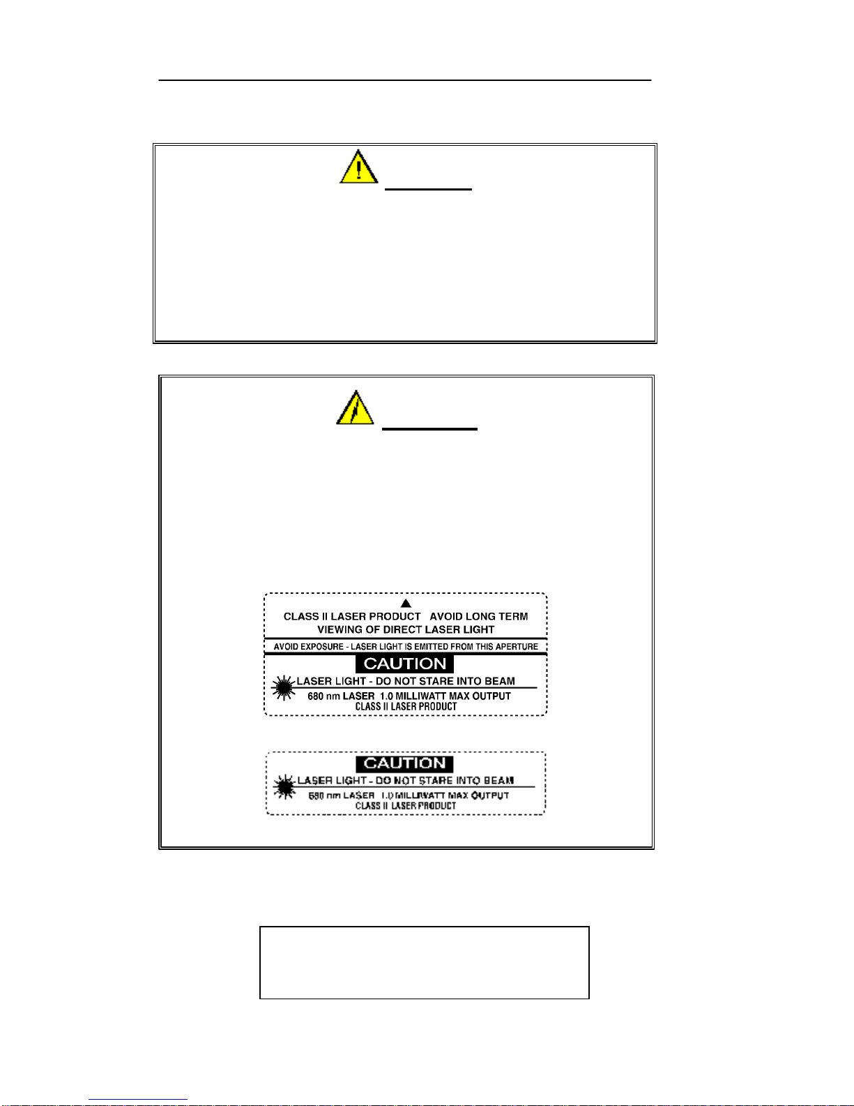
The following exposure label is a reproduction of the label mounted
inside the Apex Portable Data Collection Terminal.
CAUTION – Laser Light when open.
DO NOT STARE INTO BEAM
WARNING!
FAILURE TO ADHERE TO WARNINGS,
CAUTIONS, AND APPROVED PROCEDURES COULD
RESULT IN EXPOSURE TO HARMFUL,
VISIBLE LIGHT RADIATION!
The following Caution Label is mounted on the Apex Port
able
Data Collection Terminal to caution users of the possible effects
of laser radiation.
Apex III Caution Label
Page 17
Apex PDT Technical Reference Manual 2 Safety
COAM30002 Rev. 2.00 8/13/02 2-3
Long Range And Advanced Long Range Laser
The Compsee, Inc. Apex Portable Data Collection Terminal is
available with an optional Long Range or Advanced Long Range
Laser designed and manufactured to exacting standards of
performance, reliability and safety. This device emits visible laser
light radiation, which can be harmful to the eyes if viewed directly.
Certain warnings and precautions, in addition to the operating and
care instructions in this manual, are provided for safe operation of
this product.
The integrity of the unit case is critical to the performance and safe
operation of the product. In the event that the case becomes broken,
loose, cracked, or perforated, operation of the unit should cease
immediately. Only after authorized personnel have repaired the unit,
should operation of the unit resume. It is recommended that
personnel using this device DO NOT look directly into the Scanner
Beam while operating the device.
WARNING!
DO TAMPER WITH THE UNIT CASE!
DO NOT operate the scanner if case is perforated, broken, or
loosely held together. Use of the product with the case broken,
perforated, or loose could result in damage to the eyes if laser light
is viewed directly.
CAUTION!
USE ONLY COMPSEE APPROVED METHODOLOGY
DO NOT use the Apex PDT for uses other than those specified by
Compsee, Inc. Use of controls, adjustments, procedures, or
methodology other than those specifically identified by Compsee,
Inc. may result in hazardous laser light exposure.
Page 18
Apex PDT Technical Reference Manual 2 Safety
COAM30002 Rev. 2.00 8/13/02 2-4
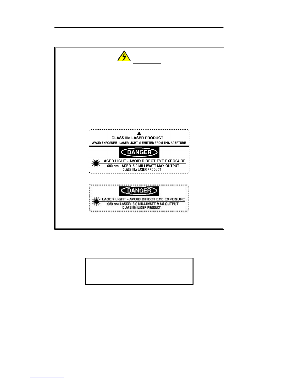
The following exposure label is a reproduction of the label mounted
inside the Apex Portable Data Collection Terminal.
DANGER – Laser Light when open.
AVOID DIRECT EYE EXPOSURE
DANGER!
THE LASER SCANNER CONTAINED IN THIS COMPSE E,
INC. APEX PORTABLE DATA COLLECTION TERMINAL IS
A CLASS IIIA LASER. ANY DIRECT VIEWING OF THE
SCANNER BEAM IN THE AIMING MODE SHOULD
BE AVOIDED.
The following Danger Label is mounted on the Apex Portable
Data Collection Terminal to warn users of the pos
sible effects
of laser radiation.
Apex III Danger Label
Apex IV Danger Label
Page 19

Apex PDT Technical Reference Manual 2 Safety
COAM30002 Rev. 2.00 8/13/02 2-5
Battery Pack Notes And Safety
1. Since Apex III and Apex IV PDT Battery Packs utilize Nickel
Metal-Hydride (NiMH) and Lithium-Ion (Li-Ion) composition
respectively, they DO NOT succumb to memory (hysteresis)
loss like Nickel-Cadmium (Ni-Cd) batteries. Apex PDT
Battery Packs can therefore be charged while in any state-ofcharge and do not require full discharge prior to charging;
however, it is still recommended that the Apex III PDT Battery
Pack be fully discharged periodically to reset the internal gas
gauge circuitry (not used in Apex IV PDT Battery Packs).
2. DO NOT attempt to operate the Apex PDT once it has powered
down due to a low battery condition. When the Battery Pack is
exhausted, leave the exhausted Battery Pack in the Apex PDT
until you can either charge or swap the Battery Pack with a
fully charged Battery Pack. Information in volatile memory
(RAM) will be preserved since the Apex PDT is configured so
that even with an exhausted Battery Pack enough energy is
retained to maintain the information for an extended period of
time. DO NOT leave the unit WITHOUT a Battery Pack for
more than 5 minutes.
3. DO NOT short the Apex PDT Battery Pack terminals with any
conductive material. A short across the terminals could result
in the sudden release of all of the remaining Battery Pack
energy causing an explosion or fire.
4. Apex PDT Battery Packs should be disposed of properly. DO
NOT dispose of the Apex PDT Battery Pack in a flame or fire.
An explosion may occur. Apex PDT Battery Packs are
approved for disposal in a class 2 Landfill (normal trash);
however, recycling the Battery Packs reduces the amount of
raw materials consumption necessary to produce new Battery
Packs and also reduces the total landfill usage within your area.
We highly recommend that the Battery Packs be returned to the
factory for recycling at the end of their useful life. Contact
Compsee, Inc. for additional information.
Page 20
Apex PDT Technical Reference Manual 2 Safety
COAM30002 Rev. 2.00 8/13/02 2-6
Product Conformity
This product complies with the Code of Federal Regulations section
21 CFR 1040.10. No user serviceable parts are included in the
manufacture. Opening of the unit by unauthorized personnel will
void the product warranty (except End Cap removal as noted in this
or other Apex PDT manuals).
Only Authorized personnel should attempt to repair or replace parts
within this unit. Breaking of the unit seal, tampering, or repair by
unauthorized personnel will void the unit warranty and could result
in personnel injury or permanent damage to the unit.
WARNING!
This equipment has been tested and found to comply with the
limits for a Class B digital device pursuant to Part 15 of the
FCC Rules. These limits are designed to provide reasonable
protection against harmful interference in a residential
installation. This equipment generates, uses, and can radiate
radio frequency energy. If the equipment is not installed and
used in accordance with instructions published in this and other
Apex PDT manuals; interference with radio communications
may result. There is no guarantee that interference will not
occur in a particular installation. If this equipment does cause
harmful interference to radio or television reception (determined
by turning the equipment ON and OFF), the user is encouraged
to try to correct the interference by one or more of the following
measures:
q Reorientation or relocation of the receiving antenna.
q Increasing the separation between the equipment and
affected receiver.
q Connecting the equipment to an outlet on a different
electrical circuit than that of the affected receiver.
q Consulting the dealer or an experienced radio/TV
technician for help.
Page 21

Apex PDT Technical Reference Manual 3 Hardware Configuration
COAM30002 Rev. 2.00 8/13/02 3-1
3 HARDWARE CONFIGURATION
Associated Pinouts
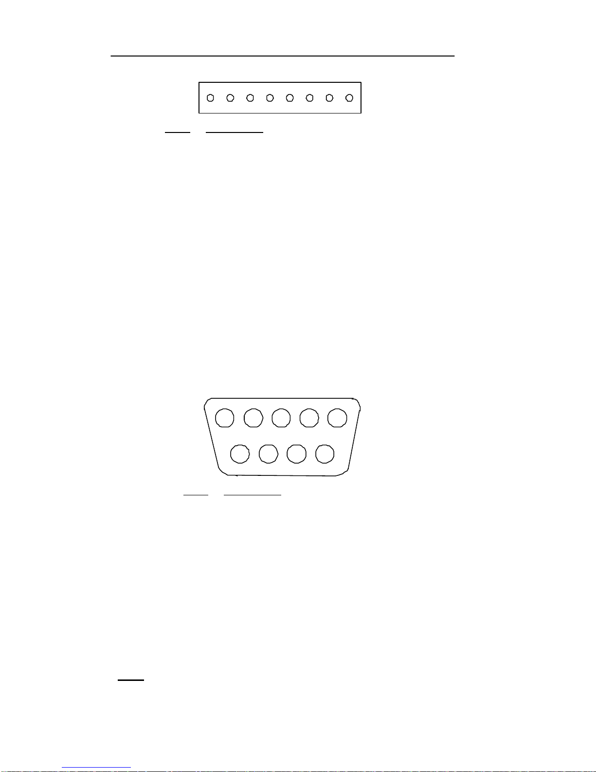
The Apex Portable Data Collection Terminal (PDT) comes standard
with an onboard RS-232 connector located within the unit on the
main circuit board. The connector is an 8-pin Molex connector
(Molex 53261-0890, see Figure 3-2) located to the left of the unit’s
DIP switches. To access this connector you must first remove the
unit’s End Cap. Installation of the optional Serial End Cap
eliminates the need for removing the standard End Cap to access the
internal RS-232 port. This allows the connection to be made with a
10-pin phone type connection on the exterior of the unit (refer to the
Apex PDT User’s Manual and the Serial End Cap Installation And
Operating Instructions for additional details).
110
Pin # Description
1 +5 V (Out – see *Note and Figure 3-5, p. 3-3)
2 RXD (In)
3 TXD (Out)
4 DTR (Out)
5 GND
6 Not Used
7 RTS (Out)
8 CTS (In)
9 Not Used
10 Not Used
Figure 3-1: Serial End Cap Connector Pinout Illustration
(Looking Into Connector)
*Note: Nominal 400 mA simultaneous total current output to
Wand Port and RS-232 port.
Page 22
Apex PDT Technical Reference Manual 3 Hardware Configuration
COAM30002 Rev. 2.00 8/13/02 3-2
PIN 1 PIN8
Pin # Description
1 DTR (Out)
2 TXD (Out)
3 RTS (Out)
4 RXD (In)
5 CTS (In)
6 GND
7 Not Used
8 +5 V Out (see *Note below and Figure 3-5, p. 3-3)
Figure 3-2: Onboard Serial Connector Pinout
The Wand Port is an optional DB9 connector located near the front
of the unit (refer to Figure 3-3). This connector is used on Apex III
units that attach to tethered devices (such as light pens, CCD
devices, or tethered laser scanners). Since Apex IV PDT models
are equipped with an integrated handle, the wand port is not an
available option. The connector is mounted in the Apex III with the
5 pin side facing down. The following illustrations show the
connector pinouts for the Apex III associated connectors and cables.
1 2 3 4 5
6
7 8 9
Pin # Description
1 Start of Scan (SOS)
2 Bar Code Data
3 Good Read LED
4 +5 V (Out – see *Note)
5 Trigger
6 Laser Enable
7 Ground
8 Shield
9 +5 V (Out – see *Note)
Figure 3-3: Apex III Wand Port Pinout
(Male DB9 Squeeze-Lock Connector)
*Note: Nominal 400 mA simultaneous total current output to
Wand Port and RS-232 port.
Page 23
Apex PDT Technical Reference Manual 3 Hardware Configuration
COAM30002 Rev. 2.00 8/13/02 3-3
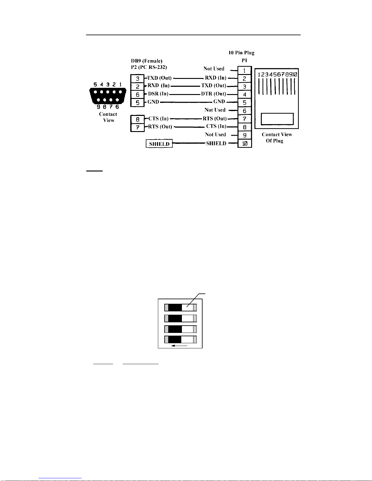
Figure 3-4: RS-232 To DB9 Cable (PN 0227001)
Note: Additional RS-232 cables are available from Compsee,
Inc. These cables can be used in conjunction with the
Apex PDT for additional purposes.
DIP Switch Configuration
An onboard DIP switch assembly is located on the main circuit
board within the Apex PDT. Access to the DIP switches (4) is
gained by removing the End Cap. In the normal operational
configuration the DIP switches are ALL in the OFF position.
During periods when the Apex PDT basic configuration requires
changing, the DIP switch position must be changed. Note that only
a qualified technician should change the DIP Switch position.
Refer to the following illustration for configuration information:
O
1
2
3
4
Switch
(white)
N
Switch Description
1 Not allocated to any function at this time.
2 Not allocated to any function at this time.
3 OFF for Normal operation, ON to boot from the PC Card slot.
ONLY for use during BIOS upgrade using a PC Card.
4 OFF for Normal operation, ON to place +5 V on the internal
RS-232 port, pin 8 (+5 V on Pin 1 of Serial End Cap if
installed).
Figure 3-5: DIP Switch Configuration
Page 24

Apex PDT Technical Reference Manual 3 Hardware Configuration
COAM30002 Rev. 2.00 8/13/02 3-4
System Architecture
Item Description
Processor
AMD Elan AM486 SC400, Low power 32-bit
microcontroller w/System logic
8 KB L1 cache
33 MHz clock speed
BIOS
PhoenixPICO BIOS
Operating System
Datalight ROM-DOS 6.22
Memory
8 or 16 MB Flash (DOS, application, and data storage)
4 MB RAM (for system operation and virtual disk data
storage)
PCMCIA card support for up to 64 MB Linear Flash
cards, 512 MB ATA Flash, and 64 MB RAM
Drive A:
System Boot Drive (Read Only)
The Apex PDT boots from the A: [config.sys] and
[autoexec.bat] files with links to secondary [config.sys]
and [autoexec.bat] files on the C: drive.
Drive B:
Placeholder – Read Only.
Drive C:
Mass Storage Drive – 4 MB (operational drive
containing secondary [config.sys] and [autoexec.bat]
files as well as additional files for normal operation).
Table 3-1: System Architecture
Page 25
Apex PDT Technical Reference Manual 3 Hardware Configuration
COAM30002 Rev. 2.00 8/13/02 3-5
Apex PDT Memory Map
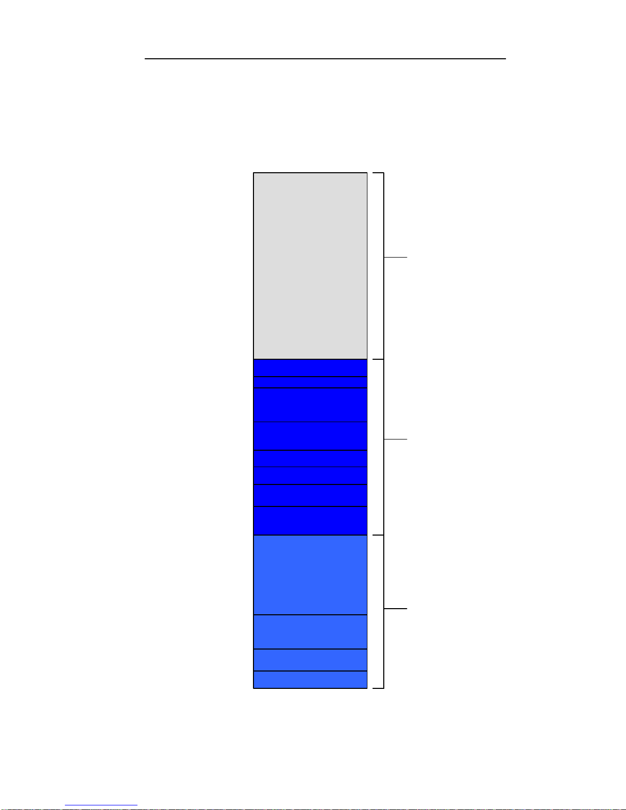
The memory map below displays the physical description and usage
of the Apex PDT RAM as configured from the factory.
3FFFFFh
Conventional
Memory
(640 KB)
00000h
A0000h
D0000h
E0000h
100000h
B8000h
C0000h
B0000h
Upper
Memory Area
(384 KB)
Extended
Memory
(3 MB)
BC000h
BIOS
Card & Socket Services
Memory Window
(if installed and defined)
Read Only
(reserved)
MCGA Font Buffers
CGA Video RAM
Read Only
(reserved)
Read Only
(reserved)
DOS RAM
ROM-DOS
BIOS Data Area
Vectors
Figure 3-6: Apex PDT Memory Map
Page 26

Apex PDT Technical Reference Manual 3 Hardware Configuration
COAM30002 Rev. 2.00 8/13/02 3-6
Display
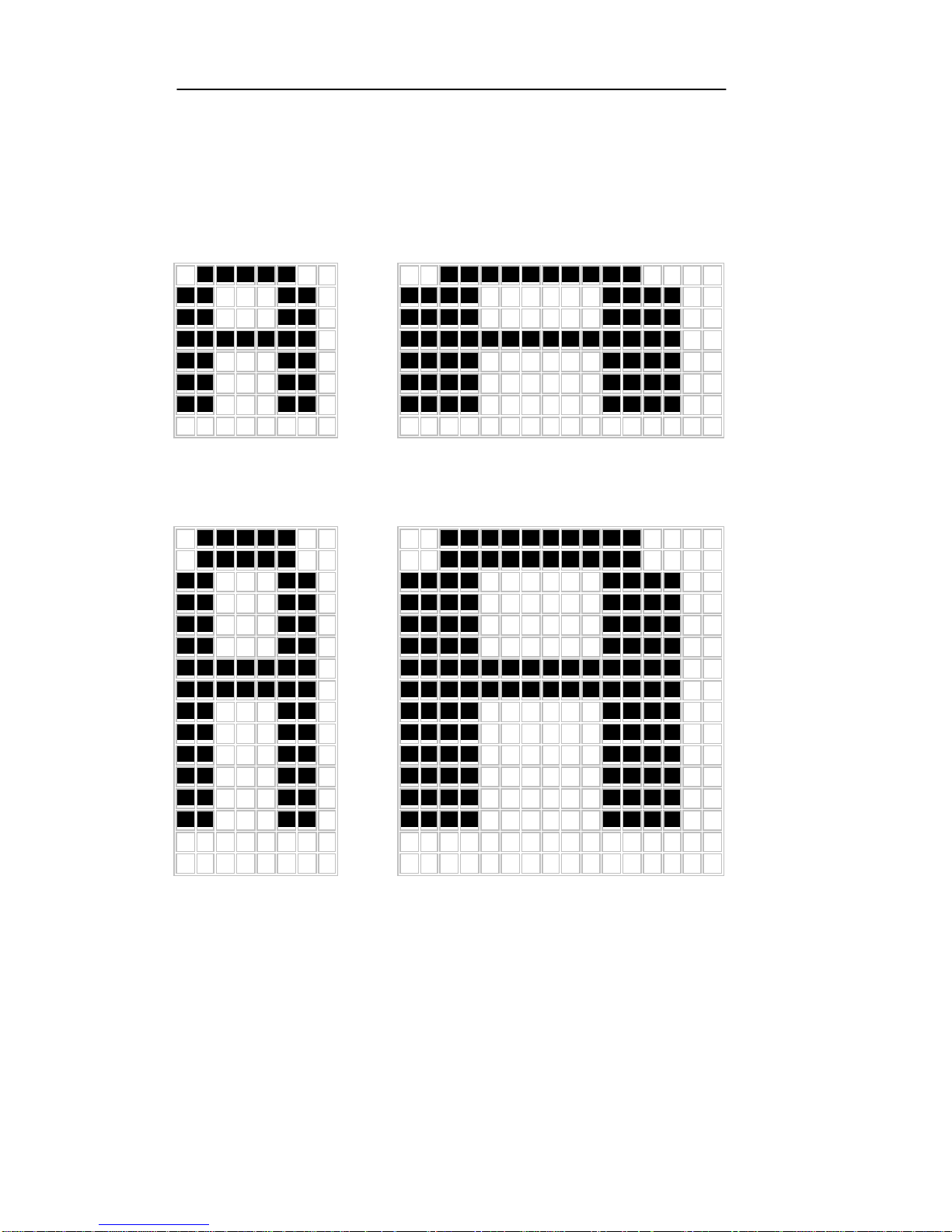
T he Apex PDT is capable of displaying information using four (4)
different font sizes (8 × 8, 16 × 8, 8 × 16, and 16 × 16). By utilizing
the various methods described in this section, a programmer can
specifically tailor the informational display for the benefit of the
end user.
The Apex PDT Display Screen functions in standard CGA modes 0
through 6 and is capable of black, white, and shades of gray. A
programmer can use the normal font (8 × 8) or change to the 16 × 8
font by changing the video mode as indicated in Table 3-2.
Furthermore, the font height can be doubled to produce two new
font sizes (8 × 16 and 16 × 16) by utilizing the additional CGA
features incorporated into the unit. For a detailed description of this
operation, refer to the Font Height Adjustments and Font Display
Illustrations sections on the following pages.
Video
Mode Colors
Virtual
Screen Size
Visible
Screen Size
Font
Size
0 16 grey
40 × 25 text 15 × 20 text 16 × 8
1 16*
40 × 25 text 15 × 20 text 16 × 8
2 16 grey
80 × 25 text 30 × 20 text 8 × 8
3 16*
80 × 25 text 30 × 20 text 8 × 8
4 4*
320 × 200 graphics 120 × 160
N/A
5 4 grey
320 × 200 graphics 120 × 160
N/A
6 2 (B&W)
640 × 200 graphics 240 × 160
N/A
Table 3-2: Apex PDT Supported Standard CGA Modes
*Note: Shades of grey are displayed due to the Apex PDT’s
display LCD characteristics.
Since the Apex PDT Display Screen is a Liquid Crystal Display
(LCD) it is not subject to “image burn” like a Cathode Ray Tube
(CRT).
The BIOS data area will indicate to an asking application program
the visible screen size being utilized. The visible display is mapped
to the upper, left-hand corner of the virtual display. Because of the
screen's physical size, the full virtual area is not viewable within the
display area.
Page 27

Apex PDT Technical Reference Manual 3 Hardware Configuration
COAM30002 Rev. 2.00 8/13/02 3-7
Font Height Adjustments
As shown in the previous section, while in Mode 0 or 1 the default
font size is 16 × 8. Within these modes, application programmers
can change the font height by using BIOS interrupt 10h, producing
a 16 × 16 high font, thereby changing the viewable area to 15
columns by 10 rows. While in Mode 2 or 3, the default font is
8 × 8. Using BIOS interrupt 10h to change the font height in these
modes produces a font size of 8 × 16 high, thereby changing the
viewable area to 30 columns by 10 rows.
Additional resources available to programmers for performing font
and screen changes are as follows:
q The [fontsize.exe] utility program (preloaded into the PDT).
With this utility, programmers can select any of the four font
sizes previously described. Refer to the Utility Program
section of this manual for detailed information on this program.
q Refer to Chapter 6 Utility Programs, BCDr iver Programming
section (p. 6-11) for low-level API information.
q Refer to Chapter 7 for high-level API information.
Page 28
Apex PDT Technical Reference Manual 3 Hardware Configuration
COAM30002 Rev. 2.00 8/13/02 3-8
Font Display Illustrations
8 ××8
Video Mode 2 or 3
Int 10h, Service 1102h
Figure 3-7
8 ××16
Video Mode 2 or 3
Int 10h, Service 1104h
Figure 3-8
16 ××8
Video Mode 0 or 1
Int 10h, Service 1102h
Figure 3-9
16 ××16
Video Mode 0 or 1
Int 10h, Service 1104h
Figure 3-10
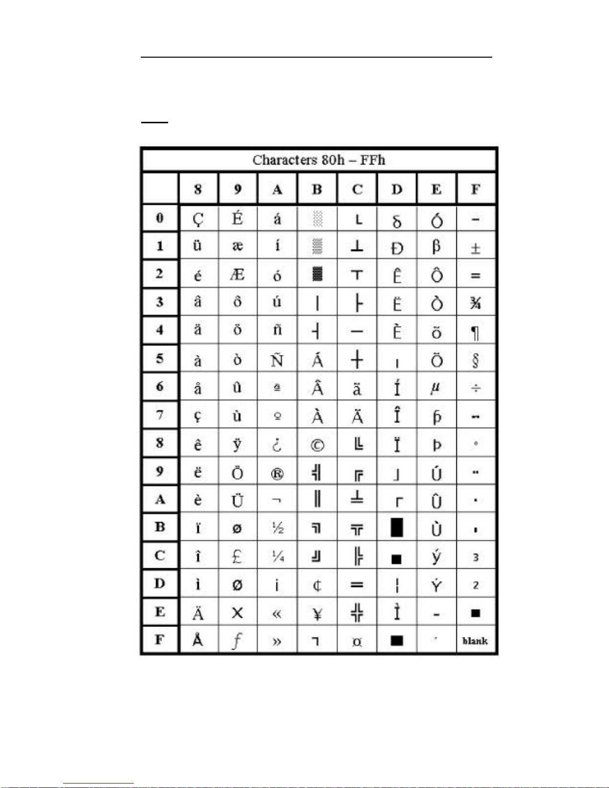
Supported Character Sets
The default font is the standard IBM Extended Character Set.
Foreign character fonts may be loaded using the [loadfont.exe]
utility program. The [loadfont.exe] program and the Latin-1 font
can be found on the Compsee Product Support CD. Other fonts are
av ailable from Compsee, Inc. upon request.
Refer to the Utility section of this manual for additional details.
Page 29
Apex PDT Technical Reference Manual 3 Hardware Configuration
COAM30002 Rev. 2.00 8/13/02 3-9
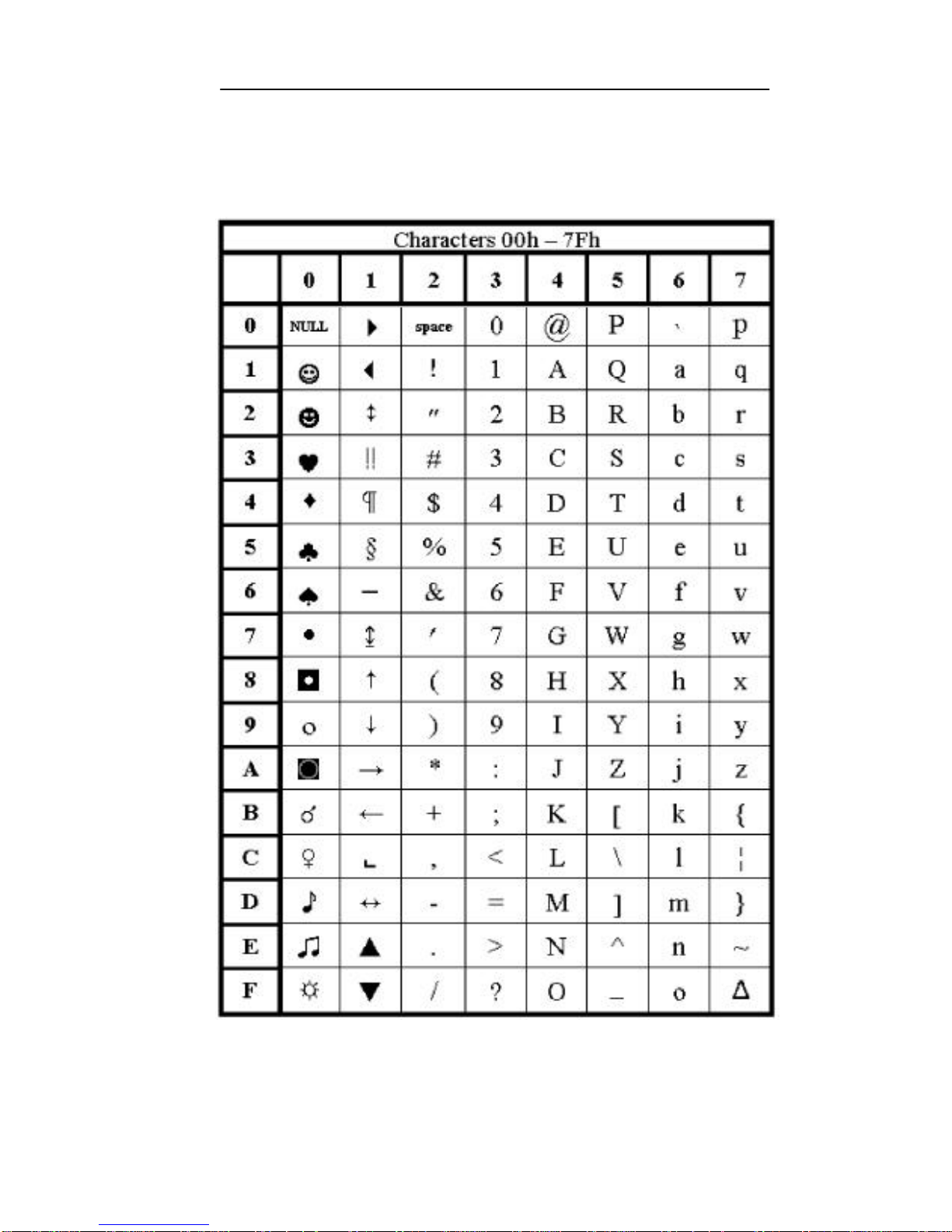
Standard ASCII Characters
Table 3-3: Standard ASCII Character Set
Page 30
Apex PDT Technical Reference Manual 3 Hardware Configuration
COAM30002 Rev. 2.00 8/13/02 3-10
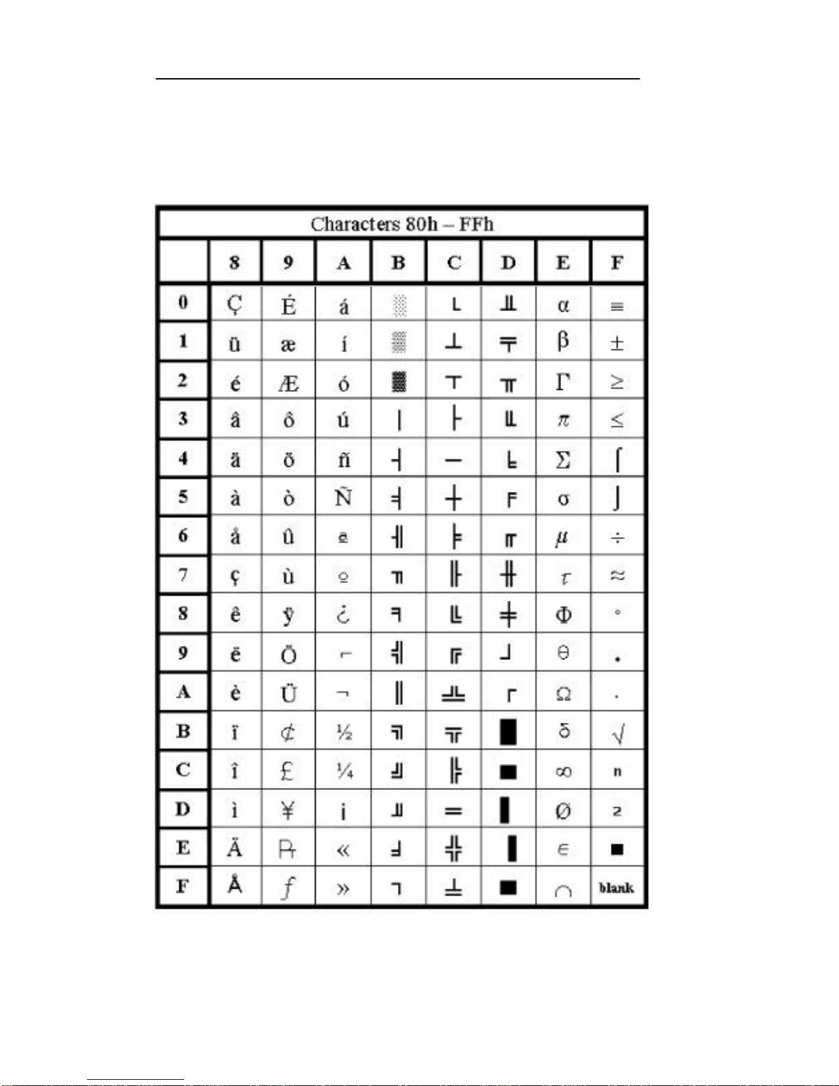
Extended ASCII Characters
Table 3-4: Extended ASCII Character Set
Page 31
Apex PDT Technical Reference Manual 3 Hardware Configuration
COAM30002 Rev. 2.00 8/13/02 3-11
Latin-1 Character Set
Note: The first 128 Latin-1 characters are the same as in the
Standard ASCII Character set and are therefore not shown.
Table 3-5: Extended Latin-1 Character Set
Page 32

Apex PDT Technical Reference Manual 3 Hardware Configuration
COAM30002 Rev. 2.00 8/13/02 3-12
Keyboard
The following table lists the keyboard codes used in the Apex
Portable Data Collection Terminal. A number within parentheses
shown in the table denotes a note. Notes are listed after the last
page of the table.
Key Normal Shift Ctrl Alt Fn
<1> 1 ! (undefined)(5) (4) <
<2> 2 @ [NULL] (4) _
<3> 3 # (4) (4) :
<4> 4 $ (4) (4) ,
<5> 5 % (4) (4) <6> 6 ^ [RS] (4) ;
<7> 7 & (4) (4) |
<8> 8 * (4) (4) +
<9> 9 ( (4) (4) “
<.> . > (4) (4) \
<0> 0 ) (4) (4) =
<SPACE> <space> <space> <space> <space> ‘
<A> a A [SOH] (4) ~
<B> b B [STX] (4) {battery}(6)
<C> c C [ETX] (4) {contrast up} (7)
<D> d D [EOT] (4) {contrast dn}(8)
<E> e E [ENQ] (4) <esc>
<F> f F [ACK] (4) `
<G> g G [BEL] (4) (undefined) (5)
<H> h H [BKSP] (4) (undefined) (5)
<I> I I [HT] (4) <tab>
<J> j J [LF] (4) <SysReq>
<K> k K [VT] (4) {inverse}(9)
<L> l L [FF] (4) {backlight} (10)
<M> m M [CR] (4) (4)
<N> n N [SO] (4) (undefined) (5)
<O> o O [SI] (4) /
<P> p P [DLE] (4) <PrtScrn>
<Q> q Q [DC1](Xon) (4) ?
<R> r R [DC2] (4) {
<S> s S [DC3](Xoff) (4) }
<T> t T [DC4] (4) {time/date}(11)
<U> u U [NAK] (4) <break> (1)
<V> v V [SYN] (4) {volume}(12)
<W> w W [ETB] (4) [
<X> x X [CAN] (4) ]
<Y> y Y [EM] (4) <pause>
<Z> z Z [SUB] (4) (undefined) (5)
<DEL> <del> (3) . (3) (4) (undefined) (5) <ctrl><F8>
<BKSP> <BKSP> < BKSP > (ascii)<del> (undefined) (5) <insert>
<ENT> (left) <enter> <enter> [LF] <alt><enter> (undefined) (5)
<ENT> (right) <enter> (3) <enter> (3) [LF] (3) <alt><enter> (3) (undefined) (5)
<SCAN> <scan> (2) <scan> (2) (undefined)(5) (undefined) (5) (undefined) (5)
Table 3-6: Apex PDT Keyboard Codes
Page 33
Apex PDT Technical Reference Manual 3 Hardware Configuration
COAM30002 Rev. 2.00 8/13/02 3-13
Key Normal Shift Ctrl Alt Fn
<up> <up> (3) 8 (3) (4) (4) <page_up> (3)
<dn> <dn> (3) 2 (3) (4) (4) <page_dn> (3)
<left> <left> (3) 4 (3) (4) (4) <home> (3)
<right> <right> (3) 6 (3) (4) (4) <end> (3)
<F1> <F1> <F5> (4) (4) <F9>
<F2> <F2> <F6> (4) (4) <F10>
<F3> <F3> <F7> (4) (4) <F11>
<F4> <F4> <F8> (4) (4) <F12>
<SHIFT> <capslock>
<ALT> (undefined) (5)
<CTRL> (undefined) (5)
Table 3-6: Apex PDT Keyboard Codes (Continued)
Notes:
(1) Returns <ctrl><break> to system.
(2) <SCAN> returns 62h scan code, normally undefined by DOS (BIOS
translates to an extended 38h).
(3) Returns the numeric keypad scan codes.
(4) Unless otherwise noted, any key + the <SHIFT>, <CTRL>, or <ALT>
key generates a scan code identical to the DOS standard definition for
that key combination.
(5) (undefined) implies that no key code is returned to the BIOS or DOS.
(6) {battery} returns 64h (BIOS translates to an extended 3Ah). Displays
the remaining battery capacity in a pop-up window if Compsee BIOS
extender TSR is loaded.
(7) {contrast up} Increases LCD contrast.
(8) {contrast dn} Decreases LCD contrast.
(9) {inverse} Inverts the video black and white.
(10) {backlight} Toggles the display backlight ON/OFF.
(11) {time/date} returns 63h (BIOS translates to an extended 39h).
Displays the current DOS time and date in a pop-up window if
Compsee BIOS extender TSR is loaded.
(12) {volume} Adjusts volume level in steps of: OFF, 1, 2, 3, (OFF)…
The following keys, found on a standard IBM-PC compatible keyboard, are
NOT implemented on the Apex PDT keypad:
Right Shift Page Up* Delete*
Right Alt Page Down* Up Arrow*
Right Ctrl Home* Down Arrow*
Num Lock End* Left Arrow*
Scroll Lock Insert* Right Arrow*
Numeric keypad keys: 0, 1, 3, 5, 7, 9, /, *, -, +
*Note : The Numeric keypad counterpart for these keys is
implemented on the Ape x PDT.
Table 3-7: Apex Keypad Compatibility
Page 34

Apex PDT Technical Reference Manual 3 Hardware Configuration
COAM30002 Rev. 2.00 8/13/02 3-14
Apex Specific ROM BIOS Extensions
Extension Summary
BIOS Interrupt 10h - Video
Function No. Service No. Description
ah = 11h al = 02h Set 8 high font
al = 04h Set 15 high font
BIOS Interrupt 15h - System
Function No. Service No. Description
ah = 55h al = 00h Get beeper volume
al = 01h Set beeper volume
al = 02h Volume next
al = 03h Get infrared port state
al = 04h Enable infrared port
al = 05h Get backlight state
al = 06h Set backlight
al = 07h Get video polarity
al = 08h Set video polarity
al = 09h Get screen contrast
al = 0Ah Set screen contrast
al = 0Bh Contrast darker
al = 0Ch Contrast lighter
al = 0Dh Get default keyclick
al = 0Eh Set default keyclick
al = 0Fh Get default typematic delay and
repeat rate
al = 10h Set default typematic delay and
repeat rate
al = 00h Get gauge
al = 00h BIOS version
BIOS Interrupt 16h - Keyboard
Function No. Service No. Description
ah = 03h al = 05h Set typematic rate and delay
ah = 04h Set keyclick
Page 35

Apex PDT Technical Reference Manual 3 Hardware Configuration
COAM30002 Rev. 2.00 8/13/02 3-15
Detailed BIOS Interrupt Information
BIOS Interrupt 10h – Video Functions
Function 11h, Service 02h – Set 8 High Font
Input:
ah = 11h
al = 02h to set 8 high font
Returns:
Carry Flag clear if successful
Carry Flag set on error
Notes:
q This function sets the Apex PDT displayed font
height to 8.
q Using an 8 high font results in a 20 row display.
q The current number of screen rows minus one can be
accessed through logical address 0040h:0084h. A
value of 19 implies an 8 high font is in use.
q Changing the video mode resets the font size;
therefore, this function should be called after the
video mode has been set.
Function 11h, Service 04h – Set 16 High Font
Input:
ah = 11h
al = 04h to set 16 hig h font
Returns:
Carry Flag clear if successful
Carry Flag set on error
Notes:
q This function sets the Apex PDT displayed font
height to 16.
q Using an 16 high font results in a 10 row display.
q The current number of screen rows minus one can be
accessed through logical address 0040h:0084h. A
value of 9 implies a 16 high font is in use.
q Changing the video mode resets the font size;
therefore, this function should be called after the
video mode has been set.
Page 36

Apex PDT Technical Reference Manual 3 Hardware Configuration
COAM30002 Rev. 2.00 8/13/02 3-16
BIOS Interrupt 15h - System
Function 55h, Servic e 00h – Get Beeper Volume
Input:
ah = 55h
al = 00h
Returns:
Carry Flag clear if successful
ax = current setting (0 = off, 1 = low, 2 = med, 3 =
high)
Carry Flag set on error
Notes:
This function retrieves the current volume setting of the
Apex PDT inte rnal beeper.
Function 55h, Service 01h – Set Beeper Volume
Input:
ah = 55h
al = 01h
bx = volume setting (0 = off, 1 = low, 2 = med, 3 = high)
Returns:
Carry Flag clear if successful
ax = current setting (after change)
Carry Flag set on error
Notes:
This function is used to set the Apex PDT internal beeper
volume to the desired level.
Function 55h, Service 02h – Volume Next
Input:
ah = 55h
al = 02h
Returns:
Carry Flag clear if successful
ax = current setting (after change)
Carry Flag set on error
Notes:
This function increases the Apex PDT internal beeper
volume from its current setting to the next higher setting.
Volume steps from high (3) to off (0).
Page 37

Apex PDT Technical Reference Manual 3 Hardware Configuration
COAM30002 Rev. 2.00 8/13/02 3-17
Function 55h, Service 03h –
Get Infrared Port State
Input:
ah = 55h
al = 03h
Returns:
Carry Flag clear if successful
ax = current setting (0 = RS-232, 1 = IR)
Carry Flag set on error
Notes:
This function retrieves the current setting of the Apex PDT
serial port. A zero (0) indicates the infrared port is
disabled (RS-232 port enabled), whereas a one (1)
indicates the infrared port is enabled (RS-232 port
disabled) for serial transmission.
Function 55h, Service 04h – Enable Infrared Port
Input:
ah = 55h
al = 04h
bx = infrared port state (0 = disable, 1 = enable)
Returns:
Carry Flag clear if successful
ax = current setting (after change)
Carry Flag set on error
Notes:
This function is used to select the active Apex PDT serial
port. A zero (0) disables the infrared port (enables RS-232
port), whereas a one (1) enables the infrared port (disables
the RS-232) for serial transmission. Only one serial device
may be enabled at a time.
Function 55h, Service 05h – Get Backlight State
Input:
ah = 55h
al = 05h
Returns:
Carry Flag clear if successful
ax = current setting (0 = off, 1 = on)
Carry Flag set on error
Notes:
This function retrieves the current state of the Apex PDT
Backlight.
Page 38

Apex PDT Technical Reference Manual 3 Hardware Configuration
COAM30002 Rev. 2.00 8/13/02 3-18
Function 55h, Service 06h – Set Backlight
Input:
ah = 55h
al = 06h
bx = backlight state (0 = off, 1 = on)
Returns:
Carry Flag clear if successful
ax = current setting (after change)
Carry Flag set on error
Notes:
This function is used to set the state of the Apex PDT
Backlight.
Function 55h, Service 07h – Get Video Polarity
Input:
ah = 55h
al = 07h
Returns:
Carry Flag clear if successful
ax = current setting (0 = normal, 1 = reversed)
Carry Flag set on error
Notes:
This function retrieves the current setting of the Apex PDT
video polarity. Normal (black text on a white background)
or reversed (white text on a black background) are the
returned settings.
Function 55h, Service 08h – Set Video Polarity
Input:
ah = 55h
al = 08h
bx = video polarity state (0 = normal, 1 = reversed)
Returns:
Carry Flag clear if successful
ax = current setting (after change)
Carry Flag set on error
Notes:
This function is used to set the Apex PDT video polarity.
Normal (black text on a white background) or reversed
(white text on a black background) are the allowable
settings.
Page 39

Apex PDT Technical Reference Manual 3 Hardware Configuration
COAM30002 Rev. 2.00 8/13/02 3-19
Function 55h, Service 09h – Get Screen Contrast
Input:
ah = 55h
al = 09h
Returns:
Carry Flag clear if successful
ax = current setting (0 to 63)
Carry Flag set on error
Notes:
This function retrieves the current contrast setting for the
Apex PDT Display.
Function 55h, Service 0Ah – Set Screen Contrast
Input:
ah = 55h
al = 0Ah
bx = contrast setting (0 to 63)
Returns:
Carry Flag clear if successful
ax = current setting (after change)
Carry Flag set on error
Notes:
This function is used to set the Apex PDT Display
contrast.
Function 55h, Service 0Bh – Contrast Darker
Input:
ah = 55h
al = 0Bh
Returns:
Carry Flag clear if successful
ax = current setting (after change)
Carry Flag set on error
Notes:
This function increases the Apex PDT Display contrast
setting by one step.
Function 55h, Service 0Ch – Contrast Lighter
Input:
ah = 55h
al = 0Ch
Returns:
Carry Flag clear if successful
ax = current setting (after change)
Carry Flag set on error
Notes:
This function decreases the Apex PDT Display contrast
setting by one step.
Page 40

Apex PDT Technical Reference Manual 3 Hardware Configuration
COAM30002 Rev. 2.00 8/13/02 3-20
Function 55h, Service 0Dh – Get Default Keyclick
Input:
ah = 55h
al = 0Dh
Returns:
Carry Flag clear if successful
ax = current setting (0 = disabled, 1 = enabled)
Carry Flag set on error
Notes:
This function returns the default keyclick state that takes
affect following a reboot. This function does NOT return
the current keyclick state.
Function 55h, Service 0Eh – Set Default Keyclick
Input:
ah = 55h
al = 0Eh
bx = keyclick state (0 = off, 1 = on)
Returns:
Carry Flag clear if successful
ax = current setting (after change)
Carry Flag set on error
Notes:
This function sets the default keyclick state. The default
takes affect following a reboot of the unit. This function
does NOT set the current keyclick state. Reference
Interrupt 16h, Function 04h.
Function 55h, Service 0Fh – Get Default Delay and Repeat
Rate
Input:
ah = 55h
al = 0Fh
Returns:
Carry Flag clear if successful
Bh = delay value (00h = 250 ms, 01h = 500 ms, 02h =
750 ms, 03h = 1000 ms)
Bl = repeat rate (see Function 55h, Service 10h Notes)
Carry Flag set on error
Notes:
This function returns the default typematic delay and
repeat rate that take affect following a reboot. This
function does NOT return the current session settings as
set by Interrupt 16h, Function 03h, but rather returns the
default settings set by Interrupt 15h, Function 55h, Service
10h.
Page 41

Apex PDT Technical Reference Manual 3 Hardware Configuration
COAM30002 Rev. 2.00 8/13/02 3-21
Function 55h, Service 10h – Set Default Delay and Repeat
Rate
Input:
ah = 55h
al = 10h
bh = delay value (00h = 250 ms, 01h = 500 ms, 02h =
750 ms, 03h = 1000 ms)
bl = repeat rate (see Notes)
Returns:
Carry Flag clear if successful
Carry Flag set on error
Notes:
q This function adjusts the default repeat rate and delay
of the keyboard. These settings take affect following
a reboot. This function does NOT set the current
session settings. Use Interrupt 16h, Function 03h to
change the current session settings.
q To set the key repeat rate use the following:
Repeat Rate (keys/sec) Value passed in BL
30 0
26.7 1
21.8 2
18.5 3
13.3 4
10.0 5
6.0 6
2.0 7
q These values are NOT the same as for Interrupt 16h,
Function 03h, Service 05h.
Page 42

Apex PDT Technical Reference Manual 3 Hardware Configuration
COAM30002 Rev. 2.00 8/13/02 3-22
Function 56h, Service 00 – Gas Gauge
Input:
ah = 56h
al = 00h
Returns:
Carry Flag clear if successful
ah= bit fields
bits 2, 1, 0 = 00h High
= 01h Low
= 02h Critical
= 03h Unknown
bits 4, 3 = 00h AC off-line
= 01h AC on-line
= 03h Unknown
al = Remaining Battery Pack capacity (0 to 100),
-1 if charging
Carry Flag set on error
Notes:
This function retrieves information about the current
power status.
Function 57h, Service 00 – BIOS Version
Input:
ah = 57h
al = 00h
Returns:
Carry Flag clear if successful
ah= major version number
al = minor version number
Carry Flag set on error
Notes:
This function returns the Apex PDT BIOS version in
decimal form. For example, values of ah = 01d and al =
34d are returned for BIOS version v1.34.
Page 43

Apex PDT Technical Reference Manual 3 Hardware Configuration
COAM30002 Rev. 2.00 8/13/02 3-23
BIOS Interrupt 16h - Keyboard
Function 03h – Set Typematic Rate and
Delay
Input:
ah = 03h
al = 05h
bh = delay value (00h = 250 ms, 01h = 500 ms, 02h = 750
ms, 03h = 1000 ms)
bl = repeat rate (see Notes)
Returns:
Carry Flag clear if successful
Carry Flag set on error
Notes:
q This function is standard for an AT BIOS but is
documented here for completeness.
q This function adjusts the repeat rate and delay of the
keyboard for the current session.
q To set the key repeat rate use the following:
Repeat Rate (keys/sec) Value pa ssed in BL
30 0
26.7 1
21.8 3
18.5 5
13.3 9
10.0 12
6.0 18
2.0 31
q These values are NOT the same as for Interrupt 15h,
Function 10h. Other rates are NOT supported by the
Apex PDT BIOS and result in error (Carry Flag set)
on return.
Page 44

Apex PDT Technical Reference Manual 3 Hardware Configuration
COAM30002 Rev. 2.00 8/13/02 3-24
Function 04h – Set Keyclick
Input:
ah = 04h
al = keyclick state (0 = off, 1 = on)
Returns:
Carry Flag clear if successful
Carry Flag set on error
Notes:
Enables or disables keyclick sound action for the current
session.
This function is not standard in an AT BIOS. It is
implemented in the Apex PDT in the same way as
documented for the PCjr.
Page 45

Apex PDT Technical Reference Manual 4 BIOS
COAM30002 Rev. 2.00 8/13/02 4-1
4 BASIC INPUT OUTPUT SYSTEM
(BIOS)
Introduction
The Apex PDT utilizes PhoenixPICO BIOS Version 4.05. When
you receive your Apex Portable Data Collection Terminal the BIOS
has already been loaded and configured by Compsee, Inc. for use
during basic unit operations.
The PhoenixPICO BIOS incorporated in the APEX PDT provides
AT Compatibility with a superior level of functionality. Apex PDT
PhoenixPICO BIOS features include the following:
BIOS Features
Basic BIOS Features
q Ultra-fast memory Testing
q Speed Independent (8254 PIT)
q Power–On Self Tests
q Coprocessor Detection
q Memory Caching
q UMB (Upper Memory Block) expansion through the release
of BIOS RAM if called upon by Memory Management
programs.
q Network Server Mode
q Support for servers without keyboards and video
q Extended Memory support greater than 64 MB
q Optional Error Message Suppression
q Optional Key Click Control
q Last-boot Failed Mode
Page 46

Apex PDT Technical Reference Manual 4 BIOS
COAM30002 Rev. 2.00 8/13/02 4-2
Advanced BIOS Features
q Boot-device Sequence Selection:
Ø A: drive followed by C: drive
Ø C: drive followed by A: drive
Ø C: drive only
q Boot-up Numlock Control
q ATA Device Automatic Configuration
q Optimal A20 Control
q Flash ROM (Read Only Memory) support. Allows BIOS
software reprogramming without ROM BIOS chip removal.
BIOS Chipset Features
q System and Video BIOS Shadowing
q Option ROM Shadowing
q Advanced Setup Menu for changing of register values
q Automatic memory sizing for Chipset Specific Memory
Configurations
q Cache sizing and control for Chipset Specific Cache
Configurations
BIOS Functions
Feature Description
Hardware
Configuration
Allocates and optimizes resources (memory,
interrupts, etc.) for each hardware component
(video, drives, etc.).
Hardware
Initialization
Performs Power-On Self Test (POST) routines
to test system resources and run the operating
system.
Runtime Routines Hardware services for DOS and applications
Table 4-1: Basic Input Output System (BIOS) Features
Page 47
Apex PDT Technical Reference Manual 4 BIOS
COAM30002 Rev. 2.00 8/13/02 4-3
BIOS Setup
With Setup (the Phoenix BIOS Setup Program), you can modify
your BIOS settings and control special features. Setup employs a
system of menus to allow the user to make changes and to turn
specific features ON or OFF.
WARNING!
ONLY KNOWLEDGEABLE PERSONNEL SHOULD ATTEMPT
TO CHANGE THE APEX PDT FACTORY
LOADED BIOS VALUES!
ONLY knowledgeable, qualified personnel should attempt to
change the factory BIOS setting. If you do enter the BIOS Setup
Menus and think you may have changed a setting by mistake,
proceed to the Exit Menu and select the Exit Without Saving
option. This will allow you to leave the BIOS Setup Menus without
changing any values or features.
Upper Level Menus and Menu Information
Follow the procedure listed below to access the Phoenix BIOS
Setup menu system:
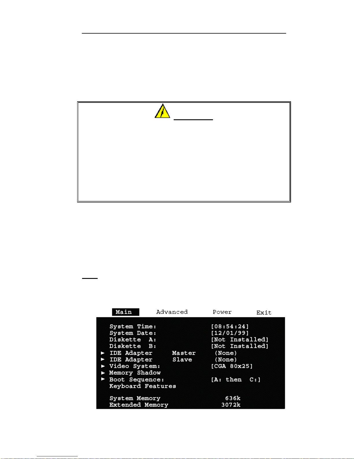
1. Turn ON or reboot your Apex PDT unit. During the boot
process press the <F2> function key to enter the BIOS Setup
Main Menu (see the following illustration).
Note: Due to the LCD screen functionality, the selected menu
item may not be completely visible. The Apex PDT screen
size may cause the right and bottom side of the selected
menu to be obscured.
Figure 4-1: BIOS Main Menu Sc reen
Page 48
Apex PDT Technical Reference Manual 4 BIOS
COAM30002 Rev. 2.00 8/13/02 4-4
2. Pressing the Down Arrow key < > or the Up Arrow key
< >, allows you to scroll up or down through the selected
menu’s items.
3. Select additional Menus by using the Right Arrow key < >
or the Left Arrow key < >. The selected menu will be
highlighted (see Figure 4-1).
4. Selected item options can be changed by pressing the
Apex PDT keys for the plus sign (+, <FN> + <8>), the
minus sign (−, <FN> + <5>), or the <SPACE> key. Once
the item has been changed to the required setting, use the Up
< >or Down < >arrow keys to go to the next item.
5. Pressing the Apex PDT Right Arrow key < > once from the
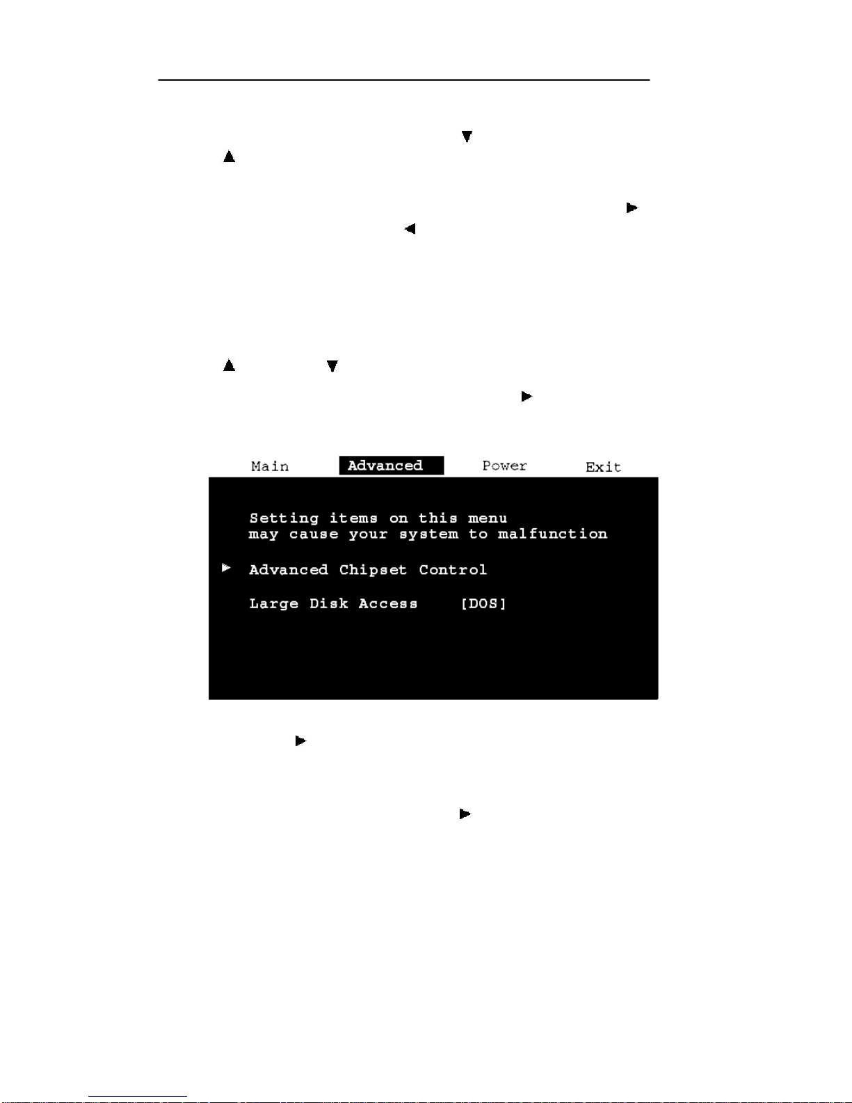
Main Menu screen displays the Advanced Menu (see Figure
4-2).
Figure 4-2: BIOS Advanced Menu Screen
6. An arrow ( ) to the left of a BIOS menu item designates
that an item specific lower level menu is available. Pressing
the Apex PDT <E NT> key will access these menus.
7. Pressing the Right Arrow key < > twice from the Main
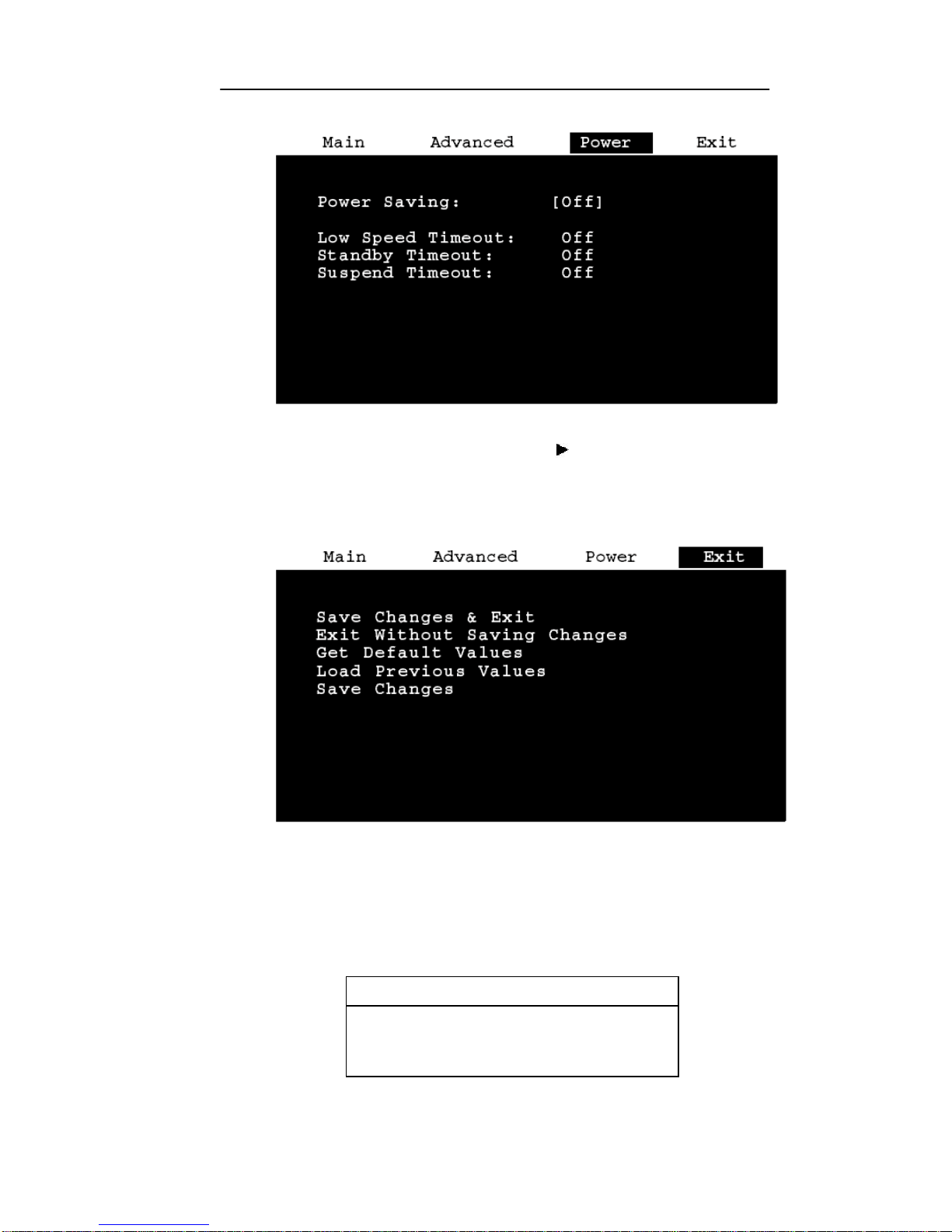
Menu screen displays the Power Menu (see Figure 4-3). For
additional information on the Power Menu options refer to
the Power Management section of this manual.
Page 49
Apex PDT Technical Reference Manual 4 BIOS
COAM30002 Rev. 2.00 8/13/02 4-5
Figure 4-3: BIOS Power Menu Screen
8. Pressing the Right Arrow key < > three times from the
Main Menu screen displays the Exit Menu (see Figure 4-4).
The Exit Me nu can also be accessed at anytime by pressing
the ESCape keys (<FN> + <E>).
Figure 4-4: BIOS Exit Menu Screen
9. Pressing the Enter <ENT> key Executes the selected
Command (such as those on the Exit Menu).
10. Selecting Get Default Values and pressing the Enter <ENT>
key causes the following notice to appear:
Notice
Default values have been loaded
[continue]
Page 50
Apex PDT Technical Reference Manual 4 BIOS
COAM30002 Rev. 2.00 8/13/02 4-6
11. Pressing the Enter <ENT> key again causes the command to
be executed and returns you to the Exit Menu.
12. Selecting Load Previous Values and pressing the Enter
<ENT> key causes the following notice to appear:
Notice
Previous values have been loaded
[continue]
13. Pressing th e Enter <ENT> key again causes the command to
be executed and returns you to the Exit Menu.
14. To exit the BIOS Setup Menus, choose the Save Changes &
Exit option or the Exit Without Saving Changes option and
press the <ENT> key. If you choose the Exit Without Saving
Changes option and you have made changes, you will be
warned about exiting without saving and must choose either
Yes or No, before returning to the Boot sequence. If you
choose the Save Changes & Exit option, the following
Notice will appear:
Notice
Changes have been saved
[continue]
15. Press the <ENT> key to return to the Boot sequence.
Lower Level BIOS Menu Screens
Main Lower Level Menus
The following screens depict the Apex PDT Lower Level BIOS
Menu default configurations.
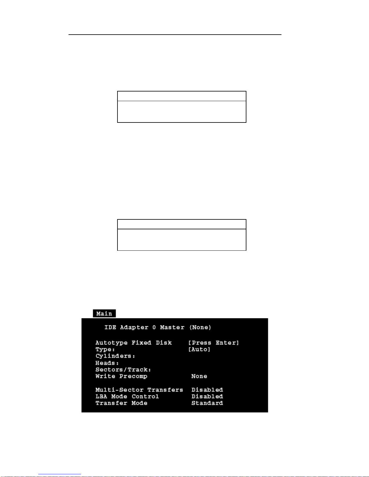
Figure 4-5: IDE Adapter Master Menu (Advanced Hard
Disk Features Installed – Apex PDT Configuration)
Page 51
Apex PDT Technical Reference Manual 4 BIOS
COAM30002 Rev. 2.00 8/13/02 4-7
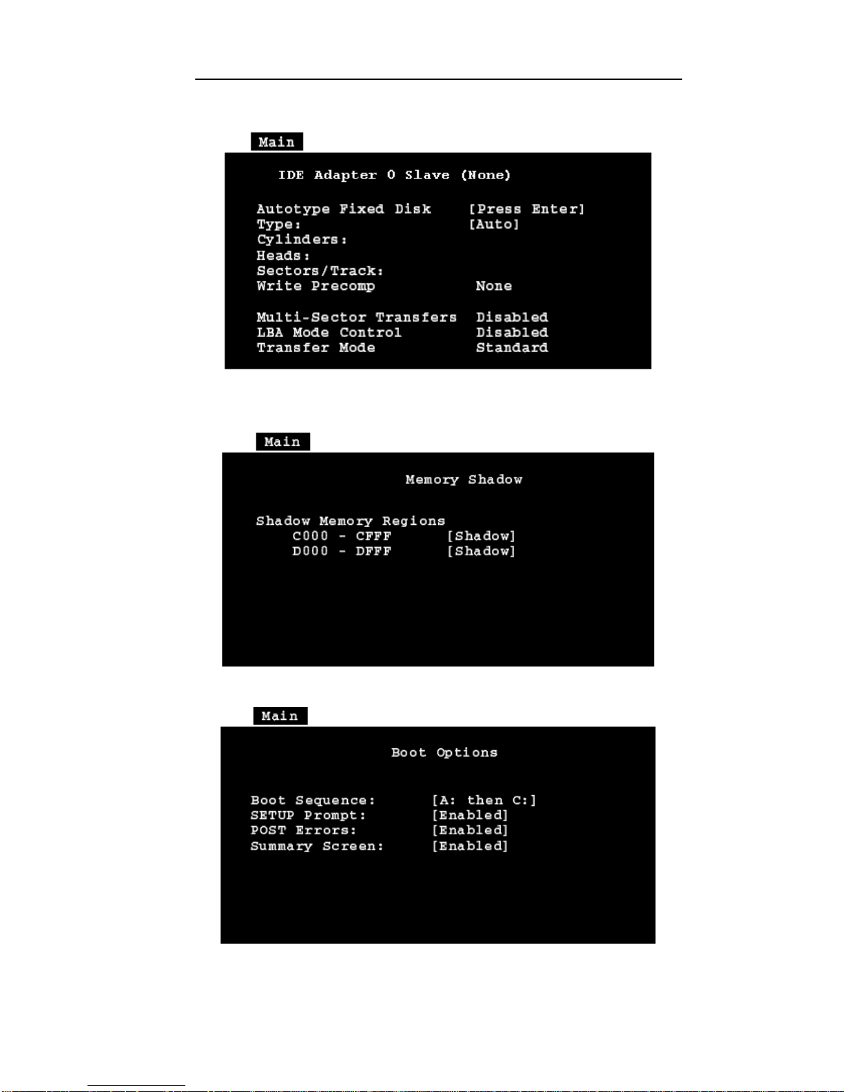
Figure 4-6: IDE Adapter Slave Menu (Advanced Hard
Disk Features Installed – Apex PDT Configuration)
Figure 4-7: Memory Shadow Menu
Figure 4-8: Boot Sequence Menu
Page 52
Apex PDT Technical Reference Manual 4 BIOS
COAM30002 Rev. 2.00 8/13/02 4-8
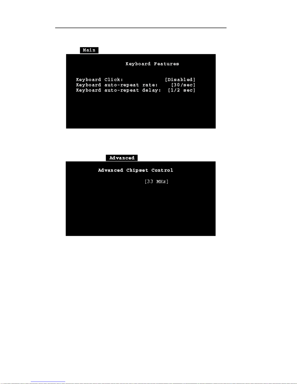
Figure 4-9: Keyboard Features Menu
Advanced Lower Level Menus
Figure 4-10: Advance Chipset Control Menu
Power Lower Level Menus
No Power Lower Level BIOS menus are used in the Apex PDT
BIOS setup. For additional information on configuring the Apex
PDT BIOS Power options refer to the Power Management section
of this manual.
Page 53

Apex PDT Technical Reference Manual 4 BIOS
COAM30002 Rev. 2.00 8/13/02 4-9
POST Errors
When an error occurs during the Power-On Self Test (POST)
sequence, the PhoenixPICO BIOS will display an error message
describing the problem. In addition, a Beep Code (one long tone
followed by two short tones) will occur during the POST sequence
if the video configuration fails or if any ROM module does not
checksum to zero.
External ROM modules if installed, can also issue an audible tone
alert (one long tone followed by a series of short tones).
Terminal POST Errors
There are several POST routines that can issue a Terminal POST
error and shutdown the system if they fail. Prior to shutting down
the system, the Terminal Error-Handler performs the following
functions:
q Issues a beep code signifying the test point error
q Attempts to initialize the video
q Writes the error in the upper left hand corn er of the screen
The beep code is derived from the test point error as follows:
1. The 8-bit error code is broken down into four 2-bit groups
(the most significant group is discarded if it is 00).
2. Each group is made one-based (1 through 4) by adding one.
3. Short beeps are generated for the number in each group.
Example: Test point 01Ah = 00 01 10 10 = 1-2-3-3 beeps
Test Points And Beep Codes
If the BIOS detects a terminal error condition, the POST is halted
after the issuance of the terminal beep code and the BIOS attempts
to display the error code in the upper left-hand corner of the screen.
The BIOS will repeatedly attempt to display the error code on the
screen.
If the system hangs up before the BIOS can process the error, the
screen will not display the error code.
The following tables display the beep codes and test point
information pertaining to the Apex PDT PhoenixPICO BIOS.
Page 54

Apex PDT Technical Reference Manual 4 BIOS
COAM30002 Rev. 2.00 8/13/02 4-10
Code Beeps POST Routine Description
000h Reset
002h Verify Real Mode
004h Get CPU type
006h Initialize system hardware
008h Initialize chipset registers with initial POST values
009h Set in POST flag
00Ah Initialize CPU registers
00Bh Enable CPU cache
00Ch Initialize caches to initial POST values
00Eh Initialize I/O
00Fh Initialize the local bus IDE
010h Initialize Power Management
011h Load alternate registers with initial POST values
012h Restore CPU control word during warm boot
014h Initialize keyboard controller
016h 1-2-2-3 BIOS ROM checksum
017h Autosize the RAM
018h 8254 timer initialization
01Ah 8237 DMA controller initialization
01Ch Reset Programmable Interrupt Controller
020h 1-3-1-1 Test DRAM refresh
022h 1-3-1-3 Test 8742 Keyboard Controller
024h Set ES segment register to 4 GB
028h Autosize DRAM
02Ah Clear 512K base RAM
02Ch 1-3-4-1 RAM failure on address line xxxx
02Eh 1-3-4-3 RAM failure on data bits xxxx of low byte of
memory bus
02Fh Shadow the BIOS
030h 1-4-1-1 RAM failure on data bits xxxx of high byte of
memory bus
034h Test CMOS RAM
036h Warm start shut down
038h Shadow the system BIOS RAM
03Ah Autosize cache
03Ch Configure advanced chipset registers
03Dh Load alternate registers with CMOS values
042h Initialize interrupt vectors
044h Initialize BIOS interrupts
046h 2-1-2-3 Check ROM copyright notice
048h Check video configuration against CMOS
Table 4-2: BIOS Test Point And Beep Code Information
Page 55

Apex PDT Technical Reference Manual 4 BIOS
COAM30002 Rev. 2.00 8/13/02 4-11
Code Beeps POST Routine Description
04Ah Initialize all video adapters in system
04Bh Displays the QuietBoot screen
04Ch Shadow video BIOS ROM
04Eh Display copyright notice
050h Display CPU type and speed
051h Initialize EISA board
052h Test keyboard
054h Set key click if enabled
056h Enable keyboard
05Ah Display prompt “Press F2 to enter Setup”
05Bh CPU Cache Off
05Ch Test RAM between 512 and 640k
060h Test extended memory
062h Test extended memory address lines
064h Jump to UserPatch1
066h Configure advance cache registers
068h Enable external and CPU caches
06Ah Display external cache size
06Ch Display shadow message
06Eh Display non-disposable segments
070h Display error messages
072h Check for configuration errors
074h Test RTC (real-time clock)
076h Check for keyboard errors
07Ah Test for key lock on
07Ch Set up hardware interrupt vectors
080h Disable onboard I/O ports.
082h Detect and install external RS232 ports
084h Detect and install external parallel ports
086h Re-initialize onboard I/O ports
088h Initialize BIOS Data Area
08Ah Initialize Extended BIOS Data Area
08Bh Test for Mouse
08Ch Initialize floppy controller
08Fh Initialize fast IDE interface
090h Initialize hard disk controller
091h Initialize local-bus hard disk controller
092h Jump to UserPatch2
093h Build MPTABLE for multi-processor boards
094h Disable A20 address line
095h Install CD ROM for boot
Table 4-2: BIOS Test Point And Beep Code Information (Continued)
Page 56

Apex PDT Technical Reference Manual 4 BIOS
COAM30002 Rev. 2.00 8/13/02 4-12
Code Beeps POST Routine Description
096h Clear huge ES segment register
098h 1-2 Search for option ROMs. One long, two short beeps
on checksum failure.
09Ah Shadow option ROMs
09Ch Set up Power Management
09Eh Enable hardware interrupts
09Fh Initialize fast IDE interface
0A0h Set time of day
0A2h Check key lock
0A4h Initialize typematic rate
0A5h Delay after initiation of the matrix keyboard
0A8h Erase F2 prompt
0AAh Scan for F2 key stroke
0ACh Enter Setup
0AEh Clear in -POST flag
0B0h Check for errors
0B2h POST done – prepare to boot operating system
0B4h 1 One short beep before boot
0B5h Clear QuietBoot screen
0B6h Check password (optional)
0BAh DMI Test point
0BCh Clear parity checkers
0BDh Display MultiBoot boot menu
0BEh Clear screen (optional)
0BFh Check virus and backup reminders
0C0h Try to boot with INT 19
0D1h Initialize Compsee Latch at 110h
Table 4-2: BIOS Test Point And Beep Code Information (Continued)
Page 57

Apex PDT Technical Reference Manual 4 BIOS
COAM30002 Rev. 2.00 8/13/02 4-13
The following table lists the Apex PDT BIOS Factory Default
Settings:
BIOS Factory Default Settings
Item
Description
Default
Setting
New
Setting
System Time Actual Time
System Date Actual Date
Diskette A: Not Installed
Diskette B: Not Installed
IDE Adapter Master None
IDE Adapter Slave None
Video System
CGA 80×25
Boot Sequence A: then C:
Advanced Chipset Control 33 MHz
Large Disk Access DOS
Power Saving Custom
Low Speed Timeout 0.125 seconds
Standby Timeout 1 minute
Suspend Timeout 60 minutes
Table 4-3: BIOS Factory Default Settings
Note: The New Setting area of the table may be used to record
settings that have been changed by the VAR/programmer
from the original factory defaults. It is recommended that
any variations from the factory defaults be recorded and
maintained in a safe location.
Page 58

Apex PDT Technical Reference Manual 4 BIOS
COAM30002 Rev. 2.00 8/13/02 4-14
Upgrading the BIOS
Periodically, Compsee, Inc. may offer or suggest that you upgrade
the Apex PDT BIOS to a newer version. Two methods are
available for performing BIOS upgrades:
q Uploading the new BIOS data from a PC using the RS-232
serial port or IR interface (th rough the Dock)
q Uploading the new BIOS data to the Apex PDT through the
PC Card slot via a BIOS Upgrade Flash card (can be
purchased pre-configured from Compsee, Inc.).
As Apex PDT BIOS upgrade configurations become available, they
will be posted on the Co mpsee, Inc. website (www.compsee.com)
as a download, or on CD or 3.5 inch floppy disk by request.
BIOS Upgrading Using A Serial Connection
Upgrading the Apex PDT BIOS may be accomplished by using the
[flashit.exe] utility pre-loaded in the BIN directory of the unit.
When using flashit, either the RS-232 Serial Port or the IR Port may
be utilized to communicate with the Apex PDT. Refer to the Utility
Programs section of this manual for detailed instructions on using
this utility.
BIOS Upgrading Using A PC Card
BIOS upgrades are available from Compsee, Inc. on a preconfigured BIOS Flash card. Using this method precludes
connecting the Apex PDT to a PC since the card automatically
boots once the Apex PDT has been properly configured. To
accomplish this form of BIOS upgrade use the following procedure:
1. Verify that the Apex PDT has been fully turned OFF (not
just in the Suspend mode) by pressing the <FN> + <Power>
keys.
2. Loosen and remove the four End Cap mounting screws using
a Phillips screwdriver.
3. Remove the End Cap from the unit.
4. Position DIP Switch 3 to the ON position (normally OFF).
A small jeweler’s screwdriver works well for this purpose.
Refer to Figure 4-11, p. 4-15.
Page 59
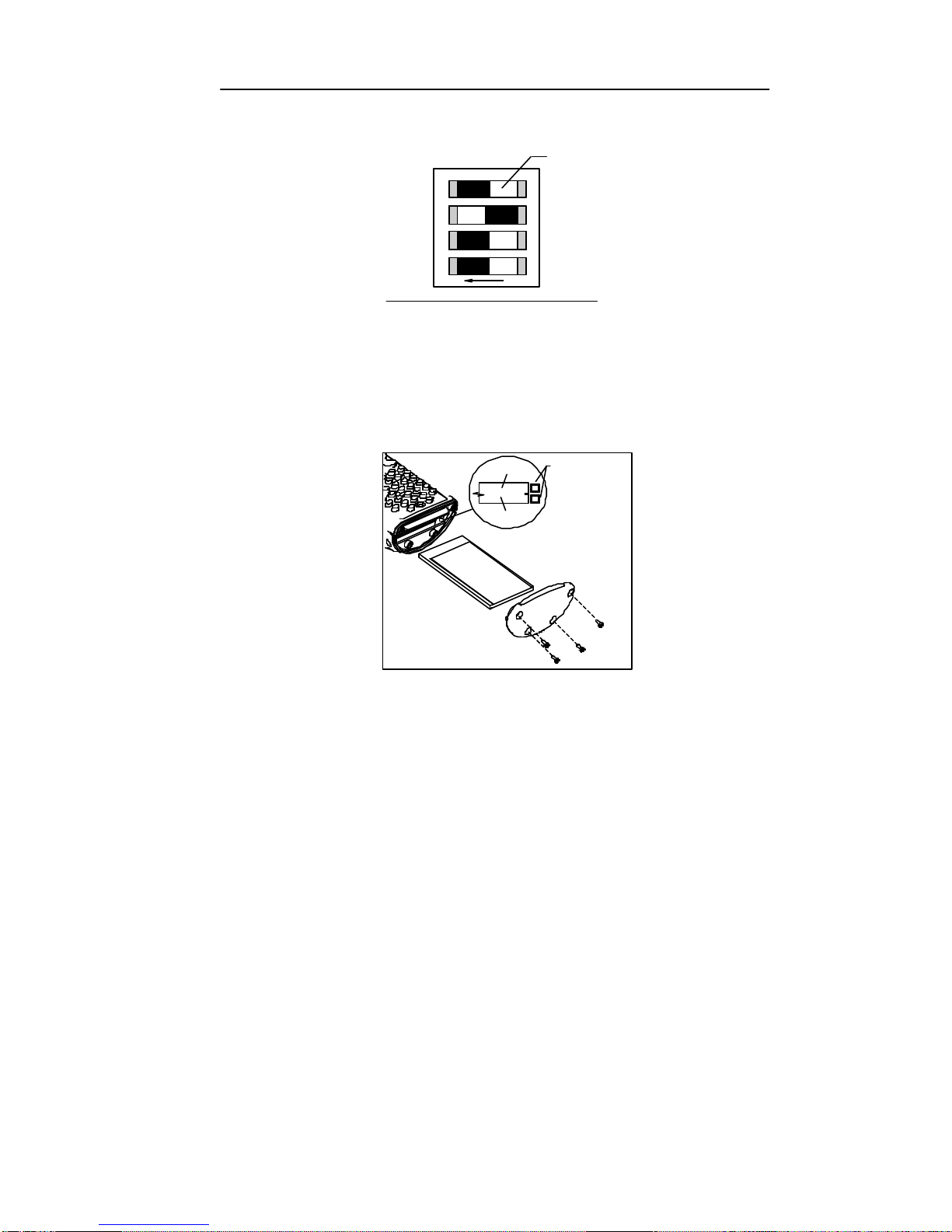
Apex PDT Technical Reference Manual 4 BIOS
COAM30002 Rev. 2.00 8/13/02 4-15
O
1
2
3
4
Switch
(white)
End Of Main Board
N
Figure 4-11: Apex PDT DIP Switch Configuration
5. Place the BIOS Upgrade Flash Card into the Slot 0 (top)
card slot with the label side down (see Figure 4-12). When
properly installed and fully seated, the card ejection button
will be out.
INSERT
CARD
LABEL
SIDE
DOWN
SLOT
SLOT
"0"
"1"
CARD EJECTION
BUTTONS
Figure 4-12: Apex PDT Card Slot Configuration
6. Power-up the unit. The Apex PDT will automatically begin
booting from the installed BIOS Upgrade Flash card (now
seen as A: Drive). After a few seconds the following
message will appear:
miniCMD>a:\crd2flsh
Card To Flash Vx.xx
This program will overwrite
the BIOS and boot disk with
the one contained on this card
at address 00000
Continue y/n [y]?
7. To continue with the BIOS upgrade press the <ENT> key.
To stop the upgrade process first press the <N> key, then the
<ENT> key.
Page 60

Apex PDT Technical Reference Manual 4 BIOS
COAM30002 Rev. 2.00 8/13/02 4-16
8. After the old BIOS version has been erased and the new
version installed the following message will appear:
The unit must be rebooted
Set switch 3 to OFF (right)
Press <scan> + <power> to reboot
9. Position DIP switch 3 back to the OFF position. It is
acceptable to perform this operation while the unit is still
powered. A small jeweler’s screwdriver works well for this
purpose.
10. Press the <SCAN> + <Power> keys to reboot the unit, have
the new BIOS take effect, and return the unit to the C:>
prompt (or application if the C: drive [autoexec.bat] has
been so configured).
11. Power down the Apex PDT by pressing the <FN> +
<Power> keys, remove the BIOS Upgrade Flash card, and
re-install the End Cap.
12. Store the BIOS Upgrade Flash Card in a safe location in the
event you need to re-perform the BIOS upgrade procedure.
For your records we recommend that you record the current
BIOS version below with the date of update.
BIOS Version Upgrade Date
Table 4-4: Installed BIOS Information
Page 61

Apex PDT Technical Reference Manual 5 Operating System
COAM30002 Rev. 2.00 8/13/02 5-1
5 OPERATING SYSTEM
Introduction
The Apex PDT utilizes the Datalight ROM-DOS operating system
(version 6.22). Designed for embedded and mobile computing
environments, ROM-DOS provides the features of MS-DOS.
ROM-DOS is fully compatible with all DOS standards and uses
device drivers making BIOS calls for all hardware communications.
While having the advantage of flexibility and compatibility, ROMDOS was independently written by Datalight to be compact and is
nearly half the size of MS-DOS.
ROM-DOS Conventions
Since ROM-DOS is fully compatible with MS-DOS, it employs
the same basic conventions as other DOS Operating Systems.
These conventions include the following:
q Two part filename structure (name.ext, with eight
character filename limitation and three character extension).
q Filename extension properties (.com, .exe, and .bat
reserved for executable and batch programs).
q Tree-structured directory system.
q Drive designations the same as MS-DOS (for the Apex PDT,
A: is the Boot Drive, B: is a placeholder drive, C: is the
mass-storage drive, and additional drives subsequent letters
as designated).
q System prompt (e.g. C:) and Command Line (area to the
right of the system prompt) used in the same fashion as
MS-DOS.
q Input and output redirection through the use of the right angle
bracket (> - output) and the left angle bracket (< - input).
Note: Refer to the ROM-DOS User’s Guide included on the
supplied Compsee Product Support CD for additional
information on ROM-DOS characteristics or features.
Page 62

Apex PDT Technical Reference Manual 5 Operating System
COAM30002 Rev. 2.00 8/13/02 5-2
Configuring ROM-DOS
Config.sys File
Certain standard settings for your system’s operation are stored in a
file named [config.sys]. You may create or edit the file using a
word processor or the COPY CON command. The file must be
placed in the root directory of the drive that is used for system
startup or boot. In the case of the Apex PDT two [config.sys] files
are used (one on the A: drive and one on the C: drive). The
A: drive is the boot drive on the Apex PDT and is a read only drive
reducing the chance of damage to the system files to ensure bootup
of the unit. The Apex PDT default [config.sys] files are shown
below:
A:\>[config.sys]
files=40
buffers=20
device=fxdos.sys
device=d000wndw.sys
NEWFILE=c:\config.sys
Note: The NEWFILE command in the last line of the
A:[config.sys] ties this file to the C:[config.sys] file shown
below.
C:\>[config.sys]
device=c:\dos\himem.sys /a20+
device=c:\dos\emm386.exe /I=a000-afff /x=b000-cfff
/x=d000-dfff /x=e000-ffff
LASTDRIVE=Z:
REM ************************
REM ** Load Phoenix Card &
REM ** Socket Services
REM ************************
REM by PicoCard V4.02a
DEVICE=C:\PICOCARD\PROGRAM\DPMS.EXE
DEVICE=C:\PICOCARD\PROGRAM\CNFIGNAM.EXE /DEFAULT
DEVICE=C:\PICOCARD\PROGRAM\PCMSS.EXE
DEVICE=C:\PICOCARD\PROGRAM\PCMCS95.EXE
DEVICE=C:\PICOCARD\PROGRAM\PCMRMAN.SYS
DEVICE=C:\PICOCARD\PROGRAM\PCMMTD.EXE
DEVICE=C:\PICOCARD\PROGRAM\PCMSCD.EXE
DEVICE=C:\PICOCARD\PROGRAM\PCMATA.SYS
DEVICE=C:\PICOCARD\PROGRAM\TFFSCS.COM /DRIVE=D SIZE=4096
Page 63

Apex PDT Technical Reference Manual 5 Operating System
COAM30002 Rev. 2.00 8/13/02 5-3
Autoexec.bat File
In addition to the [config.sys] file, device and configuration startup
commands and paths are loaded into the system operating
environment by the [autoexec.bat] file, which is also located in the
root directory. Programmers and application developers may use
this file to load their applications into the Apex PDT system.
As with the [config.sys] file, the Apex PDT utilizes two
[autoexec.bat] files (one on A: drive and one on C: drive). The
Apex PDT default [autoexec.bat] files are shown below:
A:\>[autoexec.bat]
@echo off
prompt=$p$g
path=a:\;c:\dos;c:\bin;
c:
%IF EXIST c:\autoexec.bat c:\autoexec
Note: The %IF EXIST command in the last line of the
A: [autoexec.bat] file ties the file to the
C: [autoexec.bat] file.
C:\>[autoexec.bat]
REM ************************** REM **************************
REM ** Phoenix Card & Socket REM ** Bar Code Driver
REM ** Services REM ** User setup
REM ************************** REM **
PATH=C:\PICOCARD\PROGRAM;%PATH% REM ** Remove the ‘REM’ from
REM ************************** REM ** the next line and
REM ** Infrared Port Enable REM ** include modifiers as
REM ** REM ** required by the app.
REM ** For maximum power REM **************************
REM ** savings, turn IR port REM C:\BIN\bcdriver
REM ** OFF when not in use REM **************************
REM ************************** REM ** Application
A:\IR ON REM **
REM ************************** REM ** Add application path
REM ** Bar Code Driver REM ** and name below
REM ** Factory default REM **************************
REM ************************** REM application command here
C:\BIN\bcdriver all
Page 64

Apex PDT Technical Reference Manual 5 Operating System
COAM30002 Rev. 2.00 8/13/02 5-4
Command Line Functions
Note: For a detailed description of the ROM-DOS commands
and their syntax and parameters, refer to the ROM-DOS
User’s Guide included on the Compsee Product Support
CD which came with the unit.
The command line is the area to the right of the DOS prompt
(C:\>). These commands must be loaded either during system
boot in the [config.sys] or [autoexec.bat] files (as indicated) or
from the command line. ROM-DOS commands are listed below:
Note: Table entries with a file size denoted are utility programs,
which require loading into the Apex PDT.
Command Summary
Command/(Type)
Size
(bytes) Description
?
[config.sys] command. Directs ROM-DOS to
pause for confirmation before processing a
command
@ Used to suppress the display of a single batch
file command line.
; Identifies non-executing lines. Same as the
REM command.
ANSI.SYS 3434 A console device driver that allows you to
support ANSI codes on the local screen.
ATA.SYS 9966 A PCMCIA ATA disk device driver.
ATTRIB 11300 Displays or modifies the attributes associated
with a file.
BACKUP 21544 Backup a single directory tree to a floppy disk,
hard drive, or network drive.
BREAK Turns ON or OFF the ability to stop program
execution at a non-I/O point.
BUFFERS
Used in the [config.sys] file. Sets the number
of internal data buffers.
CALL Batch file command. Invokes execution of a
secondary batch file.
CHDIR (or CD) Changes the current directory. Same as CD.
CHKDSK 18624 Checks the integrity of the data on a disk and
displays information pertaining to the same.
CHOICE 2582 Allows a user to make a processing choice
during the execution of a batch file.
Table 5-1: ROM -DOS Command Summary Information
Page 65

Apex PDT Technical Reference Manual 5 Operating System
COAM30002 Rev. 2.00 8/13/02 5-5
Command Size Description
CLS Clears information from a screen or display and
returns you to the DOS prompt (C:\>)
COMMAND.HLP 11,019
COMMAND.COM 31533 Starts a second DOS command processor.
COMM 46426 Provides the ability to communicate with a
remote ROM-DOS system. COMM supports
XMODEM file transfer, autodialing,
ZMODEM, and terminal emulation.
COPY Copies files from one storage location to
another.
COUNTRY 10597 Designates the country code for displays.
CTTY Changes the default terminal interacting with
ROM-DOS.
DATE Displays and allows revisions to the system
date information.
DEFRAG 29736 Reorganizes disk files and information to
optimize disk space and performance.
DEL Deletes specified files.
DELTREE 14264 Deletes one or more directory trees or
individual files.
DEVICE Installs a device driver into ROM-DOS.
DEVICEHIGH Loads the device driver specified into the upper
memory area if space is available.
DIR Lists the contents of a specified directory.
DISKCOPY 15236 Copies the contents of one floppy disk to
another of the same type.
ECHO Batch file command. Turns off the display of
batch file execution command lines on the
monitor or display screen.
EMM386 20864 Enables expanded memory support for capable
systems.
ERASE Erases specified files (same as DEL).
EXIT Used to exit nested running of ROM-DOS
within another program.
FCBS Specifies the number of File Control Blocks
(FCBS) open at one time. Normally specified
in the [config.sys] file.
FILES Specifies the maximum number of files, which
can be open at one time. Normally specified in
the [config.sys] file.
FIND 10928 Works as a filter to display only lines
containing a specified string.
FOR Batch file command. Performs one DOS
command on a set of files.
Table 5-1: ROM -DOS Command Summary Information (Continued)
Page 66

Apex PDT Technical Reference Manual 5 Operating System
COAM30002 Rev. 2.00 8/13/02 5-6
Command Size Description
FORMAT 35056 Initializes a disk so ROM-DOS can access the
files on that disk.
FXCHK 13990 Checks all flash disk space, stress tests each spare
unit, and displays the status of all units.
Syntax: FXCHK <drive>, where drive is the
drive letter for the unit to be checked.
FXFMT 18928 Formats flash drive (drive C:) on Apex PDT.
Syntax: FXFMT <drive> [/V], where:
drive = drive C:
/V = Volume Label
Example: Formats flash disk C: and labels the
drive as Compsee.
fxfmt C: /VCompsee
FXINFO 15254 Reports detailed low level flash information,
format characteristics, and flash array usage
information. Run in the same manner as the
CHKDSK utility.
FXRECLM 11830 Used to recover discarded flash disk space by
forcing a garbage collection. Can be run as a lowpriority background task to maintain higher than
normal flash array performance.
Syntax: fxreclm <drive> [<count>], where count
is the number of successive garbage collection
operations.
GOTO Batch file command. Moves control to a specified
line within the batch file.
HELP Lists all available ROM-DOS commands along
with a brief description.
HIMEM 5833 Extended and high memory manager for 286, 386,
and PS/2 systems.
IF Batch file command. Performs a command based
on a specified condition.
INCLUDE Allows instructions on one configuration block to
be used in another configuration block.
INSTALL Loads Terminate and Stay Resident (TSR)
programs from within the [config.sys] file
KEYB 6417 Allows keyboard layout altering for a different
language or nationality.
KEYBOARD/
KEYBRD2.SYS
Keyboard code page data files for use with the
International keyboard driver [keyb.com].
LABEL 8998 Creates, changes, or deletes a disk volume label.
LASTDRIVE Specifies the letter used and the maximum
number of drives.
Table 5-1: ROM -DOS Command Summary Information (Continued)
Page 67

Apex PDT Technical Reference Manual 5 Operating System
COAM30002 Rev. 2.00 8/13/02 5-7
Command Size Description
LOADHIGH Loads a program into the upper memory area, if
space is available.
LONGDIR 7976 Provides a directory listing of files in a single
directory including those with long file names.
MEM 7631 Displays the memory allocations within your
system.
MENUCOLOR Allows startup menu text and background color
specification.
MENUDEFAULT Sets the default menu-item choice and time-out
value for making a selection.
MENUITEM Specifies an item to be placed on the startup
menu display during system boot.
MKDIR (or MD) Creates a new subdirectory.
MODE 9968 Modifies the operation of the printer, serial
port, and active video display.
MORE 8372 Displays a text file one screen at a time.
MOVE 16446 Moves and renames files and directories.
MSCDEX 25471 Enables the use of a CDROM drive.
NEWFILE
Allows the continuation of [config.sys] file
processing from a new file.
NUMLOCK Turns the Numlock keyboard key ON or OFF.
Used from within the [config.sys] file.
PATH Displays current command search paths and
allows specification of new paths.
PAUSE Batch file command. Causes program
execution to halt until a key is pressed.
POWER Conserves system power.
PRINT 12742 Prints a list of up to 10 files.
PROMPT Resets the appearance of the system prompt.
REM A batch file command. Identifies command
lines which are not to be executed (also see ”;”).
REMDISK 12415
The remote disk program allows you to access a
disk drive on a remote system via a serial cable
and standard PC-style (8250UART) serial port.
Acts as a client program, and must be used with
[remserv.exe] (see below).
REMSERV 9761
Works as the server program for [remdisk.exe].
The server system runs the program
[remserv.exe] that can make a single drive on
the server system available to the client.
REMQUIT 106
Terminates the [remserv.exe] program via the
serial connection.
REN Renames files.
RESTORE 20684 Restores files to the hard disk, which were
previously saved using the Backup command.
Table 5-1: ROM -DOS Command Summary Information (Continued)
Page 68

Apex PDT Technical Reference Manual 5 Operating System
COAM30002 Rev. 2.00 8/13/02 5-8
Command Size Description
RMDIR (or RD) Removes or deletes the specified directory.
RSZ 31858 RSZ.EXE is a ZMODEM file transfer utility
used to transfer files over a serial port to
another machine running the ZMODEM file
transfer protocol.
SET Sets environmental variables and command
process strings.
SHARE 4228 Installs the capabilities for file sharing and file
locking on your hard drive.
SHELL Allows selection of a command interpreter
other than [command.com].
SHIFT Batch file command. Shifts replaceable
parameters one position to the left.
SORT 10960 Sorts a text file and displays the output to the
standard device.
STACKDEV.SYS Increases the number of stacks available for
IRQ handlers and Int3h.
STACKS Allows the use of dynamic data stacks to handle
interrupts.
SUBMENU Defines a secondary menu item.
SUBST 8604 Allows one drive to appear as anoth er drive.
SWITCHES
Allows special [config.sys] file options.
SYS 20396 Transfers the hidden system files to a specific
drive.
TIME Displays and allows resetting of system time.
TREE 9194 Display the path of each directory on a specific
drive.
TYPE Display the contents of a text file on the
monitor or display screen.
UMBLINK 5198 A non-protected mode program, which can
allow the creation of upper memory blocks
using existing RAM areas.
VDISK 7844 Allows the use of memory as a simulated disk
drive.
VER Display the current version of ROM-DOS on
the monitor.
VERIFY Displays the current VERIFY state or sets the
VERIFY state to ON or OFF.
VERSION.SYS 256 Modifies the version number that ROM-DOS
reports.
VOL Displays the specified disk’s volume label.
XCOPY 25544 Copies multiple files and optional
subdirectories.
Table 5-1: ROM -DOS Command Summary Information (Continued)
Page 69

Apex PDT Technical Reference Manual 5 Operating System
COAM30002 Rev. 2.00 8/13/02 5-9
Boot Drive File Information (A:)
The Apex PDT utilizes the A: drive as the boot drive. Factory
installed files on this READ ONLY drive are as follows:
Volume in drive A is BOOT_DRIVE
Directory of A:\>
COMMAND.COM 28,957 10-31-1997 6:22a
CONFIG.SYS 84 08-02-1999 3:08p
AUTOEXEC.BAT 92 12-06-1999 9:15a
REMDISK.EXE 10,019 10-31-1997 6:22a
FXDOS.SYS 16,611 12-03-1999 7:46p
D000WNDW.SYS 193 04-29-1999 8:48a
IR.COM 442 02-12-2001 10:33a
7 file(s) 56,398 bytes
[command.com]
ROM-DOS command line interpreter. Analogous to the MS-DOS
file by the same name.
[config.sys]
See previous description in this section.
[autoexec.bat]
See previous description in this section.
[remdisk.exe]
A remote disk utility program provided with Datalight ROM-DOS.
Refer to the Utility Program section of this manual for a detailed
description.
[fxdos.sys]
ROM-DOS de vice driver that makes the Apex PDT flash memory
appear as a standard high-performance disk drive to the operating
system.
[d000wndw.sys]
A temporary device driver that frees up a memory block used
during the boot process. When finished with its task, the driver will
uninstall itself thereby freeing up additional RAM.
[ir.com]
The Apex PDT’s Infrared Port Utility. Refer to the Utility Program
section of this manual for a detailed description.
Page 70

Apex PDT Technical Reference Manual 5 Operating System
COAM30002 Rev. 2.00 8/13/02 5-10
Primary Drive File Information (C:)
Note: Files listed are gi ven as an example. Actual files may vary
depending on the date your unit was issued. Contact
Compsee Inc. for an exact file listing or to receive
upgraded files. The maximum files that can be contained
within the root directory is 240.
The Apex PDT primary drive (C:) is a read/write flash drive. The
Apex PDT mass storage directory contains the following files and
directories when it comes from the factory (additional files can be
added as necessary for specific applications):
Volume in drive C is Compsee
Volume Serial Number is 64E2-A069
Directory of C:\>
DOS <DIR> 01-06-2000 5:46p
BIN <DIR> 01-06-2000 5:46p
PICOCARD <DIR> 01-06-2000 5:46p
CONFIG SYS 648 09-28-2000 1:24p
AUTOEXEC BAT 848 01-11-2001 7:52a
5 file(s) 1,553 bytes
DOS Directory Files:
VDISK.EXE
HIMEM.SYS
EMM386.EXE
POWER.EXE
REMSERV.EXE
BIN Directory Files:
BCDRIVER.EXE
CBE.EXE
FONTSIZE.EXE
DX.EXE
FLASHIT.EXE
PICOCARD Directory Files:
The files in the PicoCard directory are all the files necessary to use
the PC Card slots. Refer to the following page for a directory of
these files.
Page 71

Apex PDT Technical Reference Manual 5 Operating System
COAM30002 Rev. 2.00 8/13/02 5-11
PicoCard Program Directory
Volume in drive C is Compsee
Volume Serial Number is 64E2-A069
Directory of C:\PICOCARD\PROGRAM
. <DIR> 01-06-2000 5:46p
.. <DIR> 01-06-2000 5:46p
TFFSCS COM 33,472 04-14-1998 3:08p
DPMS EXE 47,375 03-01-1994 1:00a
CNFIGNAM EXE 1,278 04-14-1998 3:06p
PCMCS95 EXE 92,980 04-14-1998 3:08p
PCMRMAN SYS 99,392 04-14-1998 3:08p
PCMMTD EXE 21,453 04-14-1998 3:08p
PCMATA SYS 22,763 04-14-1998 3:08p
PCMSS EXE 23,449 04-19-1999 9:36a
PCMSCD EXE 43,453 04-14-1998 3:08p
PCM INI 1,657 05-06-1999 8:20a
12 file(s) 387,272 bytes
Note: Files listed above are given as an example. Actual files
loaded may vary. For a detailed description of various
PicoCard files refer to the PC Card section of this
manual.
C: Drive File Information
[vdisk.exe]
Allows the use of memory as a simulated disk drive. Refer to the
Datalight ROM-DOS manual included on the Compsee Product
Support CD.
[himem.sys]
Extended and high memory manager for 286, 386, and PS/2
systems. Refer to the Datalight ROM-DOS User’s Guide included
on the Compsee Product Support CD.
[emm386.exe]
Enables expanded memory support for capable systems. Refer to
the Datalight ROM-DOS User’s Guide included on the Compsee
Product Support CD.
Page 72

Apex PDT Technical Reference Manual 5 Operating System
COAM30002 Rev. 2.00 8/13/02 5-12
[remserv.exe]
Works as the server program for the [remdisk.exe] utility. The
server system runs the program [remserv.exe]. The [remserv.exe
program can make a single drive on the server system available to
the client (system running [remdisk.exe]).
[power.exe]
Conserves system power usage to maximize the time between
Battery Pack charges.
[bcdriver.exe]
Allows the Apex PDT to read bar codes. Refer to the Utility
Program Section of this manual for additional details.
[fontsize.exe]
Changes the displayed font size for easier readability on the Apex
PDT display screen.
[dx.exe]
A file transfer utility for transferring files to and from the Apex
PDT. Uses the YMODEM transfer protocol.
[flashit.exe]
An upgrade utility supplied by Compsee Inc. for use in upgrading
the PhoenixPICO BIOS, the ROM-DOS Operating System, and
the contents of the A: (boot) drive (all three items are updated
simultaneously). Refer to the Utility section of this manual for
detailed instructions on using this program.
[cbe.exe]
Computer BIOS extender file [cbe.exe] provides several useful
extensions to BIOS functions in the Apex PDT. The extensions are
focused in two main areas:
q Keyboard enhancem ents specific to the Apex design
q Advanced Power Management (APM) enhancements.
Page 73

Apex PDT Technical Reference Manual 6 Utility Programs
COAM30002 Rev. 2.00 8/13/02 6-1
6 UTILITY PROGRAMS
The following utility programs have been preloaded into the Apex
PDT by Compsee, Inc. or are located on the Product Support CD
included with your unit.
q [bcdriver.exe]
q [ir.com]
q [remdisk.exe]/[remserv.exe]
q [fontsize.exe]
q [loadfont.exe] (on Product Support CD)
q [dx.exe]
q [flashit.exe]
q [cbe.exe]
The utility programs discussed within this chapter allow the Apex
PDT to read bar codes, communicate with various devices, and
perform basic functions without additional programming. Your
VAR or corporate programming personnel can provide custom
application programs specifically designed for your business. The
following text is a general description of the capabilities of these
utility programs. For in -depth information on each of these utilities
refer to the specific file further on within this section of the manual.
Bar Code Driver [bcdriver.exe]
[bcdriver.exe] is a Compsee, Inc. Bar Code reading program
implemented as a DOS TSR (Terminate & Stay Resident) program.
The program requires approximately 44K of memory when running
and allows the Apex PDT programmer to stipulate usable bar code
symbologies and change certain characteristics.
Infrared Communications Utility [ir.com]
The [ir.com] program is loaded in the Apex PDT boot drive at the
factory. This utility program is used to enable or disable the Apex
PDT Infrared (IR) port, thereby enabling or disabling the Apex
PDT’s capability to perform infrared communications.
Page 74

Apex PDT Technical Reference Manual 6 Utility Programs
COAM30002 Rev. 2.00 8/13/02 6-2
Remote Disk Utilities [remdisk.exe] & [remserv.exe]
The remote disk program allows you to access a disk drive on a
remote system via a serial cable and standard RS-232 serial port. In
a remote disk setup, one system (the one that shares its drives) is the
server. The other system (the one that accesses and uses the remote
drives) is called the client. The serial ports on both systems must be
connected via a null modem cable. [remdisk.exe] and [remserv.exe]
communicate across a standard 3-pin serial cable. The cable does
not require the CTS/RTS or DSR/DTR pins.
Display Font Utility [fontsize.exe]
The [fontsize.exe] utility allows the displayed font size to be
changed for easier readability by the user or programmer. The
program allows font changes among the following font sizes; 8 × 8,
16 × 8, 8 × 16 and 16 × 16. It should be noted that changing the
font size to a larger point size will decrease the number of
characters that the screen can display at any given time.
Font Loading Utility [loadfont.exe]
The [loadfont.exe] utility allows the displayed font to be changed to
additional character sets by the user or programmer. The Latin-1
font set is supplied on the Compsee Product Support CD. Other
fonts are available from Compsee, Inc. upon request.
File T ransfer Utility [dx.exe]
The [dx.exe] utility allows file transfers to and from the Apex PDT
and a PC. Uses the YMODEM transfer protocol.
Upgrade Utility [flashit.exe]
[flashit.exe] is an upgrade utility that is used to upgrade the Apex
PDT PhoenixPICO BIOS, the ROM-DOS Operating System, and
the contents of the A: drive. Refer to the detailed description later
in this section for additional details.
Compsee BIOS Extender [cbe.exe]
A computer BIOS extender file that provides several useful
extensions to Apex PDT BIOS functions. The extensions are
focused in two main areas:
q Keyboard enhancements specific to the Apex design
q Advanced Power Management (APM) enhancements.
Page 75

Apex PDT Technical Reference Manual 6 Utility Programs
COAM30002 Rev. 2.00 8/13/02 6-3
Bar Code Driver [bcdriver.exe]
The Compsee Bar Code Driver is implemented as a Terminat e &
Stay Resident (TSR) DOS program. The program requires
approximately 44K of memory when running and allows the Apex
PDT programmer to stipulate usable bar code symbologies and
change certain characteristics.
Driver Options And Modifiers
Options
Driver options can be set using two methods.
q From the command line - Options and modifiers can be
specified on the command line when the driver is initially run
or at any other time by issuing a new command line with new
options. If the driver has not been previously loaded during
DOS booting, performing this operation will set the initial
operating parameters. If the driver is already loaded, this
method modifies the previous option settings already
installed. The command line is parsed from left to right.
q From an application, using the driver API (Application
Programming Interface). This describes a series of formal
interface functions for communicating with the driver.
Optional parameters are implemented using the following criteria:
q If an option is identified in the command line, the option is
turned ON by default.
q If the option is immediately preceded by a minus sign (−), the
option is turned OFF.
q If the option is immediately preceded by a question mark (?),
the current value of the option is returned to the screen. No
change is made to the option or its modifiers.
q All options are case insensitive. Upper and lower case may
be freely mixed for clarity.
Page 76

Apex PDT Technical Reference Manual 6 Utility Programs
COAM30002 Rev. 2.00 8/13/02 6-4
q Each option is separated from others by white space (spaces
or tabs).
q No white space is permitted between options and modifiers or
the separators (see below).
q The command line may be entered as often as desired in
order to modify the driver’s behavior after initial loading.
This feature can be used to add codes, delete codes, or change
any code’s modifiers.
Modifiers
Modifiers are implemented following the respective option. Not all
options have modifiers. Options are separated from modifiers by
either an equals sign (=) or a comma (,). Either separator may be
used interchangeably for best clarity.
All modifiers are entered as decimal integers.
Command Line Syntax
Example #1:
bcdriver all -dsym 3of9 UPCA
In Example #1, all options and modifiers are first reset to their
default values, all symbologies are next turned off, then decoding of
Code 3 of 9 (Code 39) and UPC -A is enabled.
Example #2:
bcdriver beep=250,1000 type=AIM AimTm=5
In Example #2, the good read beep duration and tone are first
changed, next the scanner type is changed to an internal laser with
aiming capabilities, and lastly the aiming dot duration is changed to
500 ms.
Page 77

Apex PDT Technical Reference Manual 6 Utility Programs
COAM30002 Rev. 2.00 8/13/02 6-5
Errors
If a syntax or out -of-range error is encountered, the driver prints a
diagnostic message on the screen indicating the failed parameter in
double quotes. A number in parentheses is also printed indicating
the portion of the parameter that the driver failed to recognize. The
following table describes the Error Code parameters:
Bar Code Driver Error Codes
Code No. Name Description
(1) BAD_OPTION
The option was not recognized or is
otherwise invalid.
(2) BAD_MOD1
The first modifier’s syntax or value was
invalid or was required, but not found.
(3) BAD_MOD2
The second modifier’s syntax or value was
invalid or was required, but not found.
Table 6-1: Bar Code Driver Error Codes
Page 78

Apex PDT Technical Reference Manual 6 Utility Programs
COAM30002 Rev. 2.00 8/13/02 6-6
BCDRIVER Options And Modifiers
Bar Code Driver Options And Modifiers
Option Modifiers Default Description
25ID Fixed length
(0 - 64)
Check digit (0 - 1)
OFF Decode Identicode 2 of 5 symbols.
The default length is 0, meaning
variable length. A Modulo 10 check
digit (included in the length) is
required if the second modifier is set
to 1. The default is 0 (no check digit).
If the second modifier is set to 1, the
check digit is validated and returned.
If the 25ID option is selected, I2of5
and 25MX are automatically
deselected.
25IN Fixed length
(0 - 64)
Check digit (0 - 1)
OFF Decode Industrial 2 of 5 symbols. The
default length is 0, meaning variable
length. A Modulo 10 check digit
(included in the length) is required if
the second modifier is set to 1. The
default is 0 (no check digit). If the
second modifier is set to 1, the check
digit is validated and returned. If the
25IN option is selected, Matrix 2 of 5
is automatically deselected.
25MX Fixed length
(0 - 64)
Check digit (0 - 1)
OFF Decode Matrix 2 of 5 symbols. The
default length is 0, meaning variable
length. A Modulo 10 check digit
(included in the length) is required if
the second modifier is set to 1. The
default is 0 (no check digit). If the
second modifier is set to 1, the check
digit is validated and returned. If the
25MX option is selected, 25IN and
25ID are automatically deselected.
3of9 Full ASCII (‘A’) ON Decode 3 of 9. If ‘A’ modifier is
included, decode as full ASCII.
Default is not full ASCII.
AimTm Time (0 - 30) 10
(1 sec)
Aim beam on time in 100 ms
increments. Only applicable if
Type=A (AIM enabled scan engine).
Setting this option to 0 will turn off
the aiming beam for an AIM enabled
scan engine.
All None YES Resets all options and modifiers to
their default values (with the
exception of the scanner type, which
is not changed). Ignores the dash and
question mark prefixes.
Table 6-2: Bar Code Driver Options And Modifiers
Page 79

Apex PDT Technical Reference Manual 6 Utility Programs
COAM30002 Rev. 2.00 8/13/02 6-7
Bar Code Driver Options And Modifiers
Option Modifiers Default Description
Beep Duration:
(0 – 500 ms)
Frequency:
(100 – 5000 Hz)
50,3136 Beep on successful decode.
Disabled if duration = 0, or using “beep”.
Btn None ON Enables or disables (“-btn”)
scanning button for activating
driver. When disabled, the
<SCAN> key will not start
scanning. The <SCAN> key
should be read by the user’s
application. The API call always
works regardless of the state of this
control. When enabled, the
<SCAN> key is absorbed by the
driver. When disabled the
<SCAN> key is placed in the
keyboard buffer normally.
C11 Check digits (1-2) ON Decode Code 11. Default is to use
2 Modulo 11 check digits. Check
digit(s) are validated, but not
returned.
C128 None ON Decode Code 128.
C93 None ON Decode Code 93.
Cbar Min c hars (3 - 64),
ABC mode
(“ABC”)
ON Decode Codabar characters. The
modifier sets the minimum number
of characters to decode including
start and stop characters, default =
5. If the ABC option is enabled,
this is the minimum total for both
groups including all start and stop
characters.
If “ABC” option is included, any
valid Codabar character group that
ends with ‘D’ will be concatenated
(linked together) to any adjacent
valid group with a ‘D’ start
character. Concatenation will
occur for any valid number of
labels in a row.
DblSc None OFF Double scan. (Redundancy check,
look for 2 identical scans before a
valid read).
Dsym None N/A Enables all symbologies that are
listed here as ON by default. Useful
to disable all standard codes (-
Dsym), then enable only the ones
desired.
EAN13 None ON Decode EAN-13 symbols.
Table 6-2: Bar Code Driver Options And Modifiers (Continued)
Page 80

Apex PDT Technical Reference Manual 6 Utility Programs
COAM30002 Rev. 2.00 8/13/02 6-8
Bar Code Driver Options And Modifiers
Option Modifiers Default Description
EAN8 None ON
Decode EAN-8 symbols.
I2of5 Fixed length
(0 - 64)
ON Decode Interleaved 2 of 5
symbols. The default length is 14.
A length of 0 means variable
length. If the I2of5 option is
selected, 25MX is automatically
deselected (default).
ID ID value
(192 – 255)
206
(0CEh)
Sets driver identifier used by API
to communicate between
applications and driver TSR. This
is alternately known as the DOS
multiplex ID. This should only be
used if the default ID conflicts
with another TSR. If changed
from default, it must always be
included on the command line
when modifying options. The ID
is set when the driver is initially
loaded, and should not be changed
on the fly.
KEID ID value 204
(0CCh)
Sets identifier used by driver to
communicate between driver and
optional keyboard extender TSR.
This is alternately known as the
DOS multiplex ID (for the
keyboard extender) . The extender
provides a much larger keyboard
buffer than the default supplied by
the BIOS, and is used when large
bar codes are anticipated. This
option should only be used if the
default ID conflicts with another
TSR’s ID. If changed from
default, the value must be
modified both here and in the
command line for the keyboard
extender, or the driver will not
make use of the extender. The
extender’s ID is set when the
extender is initially loaded, and
may not be changed on the fly.
Led On time (0 - 10) 3 sec. Sets the ON time in seconds for
the good read LED following a
successful decode.
M None None Reports memory used by driver.
Only valid when driver initially
loaded. Command line option
only.
Table 6-2: Bar Code Driver Options And Modifiers (Continued)
Page 81

Apex PDT Technical Reference Manual 6 Utility Programs
COAM30002 Rev. 2.00 8/13/02 6-9
Bar Code Driver Options And Modifiers
Option
Modifiers Default Description
MsiPl Min length
(2 - 64),
Check digits (1-2)
OFF Decode MSI Plessey symbols.
The minimum length includes the
Modulo 10 check digit(s). The
default minimum length is 2
characters. The check digit(s) are
validated, but not returned. Check
digit(s) default to 1.
Prfx Decode prefix C Adds a prefix to the decoded
symbol. See Symbol Prefixes for
details (see Table 6-3, page 6-10).
C = Compsee prefixes
A = AIM prefixes
N = No prefixes
R None N/A Remove driver if possible. DOS
drivers may only be removed if no
other TSR or driver has been
loaded after them. Only valid as
an option from the command line.
Sfx Decimal number
representing
ASCII character
(0-255)
0 (None) Adds a character to the end of the
returned string. Sfx=0 (or –Sfx)
disables suffix.
TimO Timeout
Laser range 1 - 3
(3)
Wand range 1 - 30
(5)
3 (5) Included as a safety feature. Stops
scanning after this many seconds
without successful recognition.
The default for all types is 3,
except for type WAND = 5. This
option should be set after “Type”
on the command line.
Type Type of scan
engine
Auto Set
No
action
required
Forces the scan engine type. If
this parameter is omitted, the scan
engine type is detected
automatically and set accordingly
the first time the driver is loaded.
INT - internal laser scan engine
EXT - external laser scanner
AIM - internal laser with aim
beam capability
WAND - external wand
This option should be set before
“TimO” on the command line.
UESup None OFF Enables mode where all UPC and
EAN must have a 2 or 5 character
supplement. This option may be
turned ON or OFF at any time.
Enabling or disabling UPCx or
EANx has no effect on this
setting.
Table 6-2: Bar Code Driver Options And Modifiers (Continued)
Page 82

Apex PDT Technical Reference Manual 6 Utility Programs
COAM30002 Rev. 2.00 8/13/02 6-10
UPCA None ON Decode UPC-A symbols. The
check digit is returned as part of
the decoded data.
UPCE None ON Decode UPC-E symbols. The
check digit is returned as part of
the decoded data.
Table 6-2: Bar Code Driver Options And Modifiers (Continued)
Code Types And Symbol Prefixes
Symbol Type
Code
Type
Compsee Prefix
(Prfx=C)
AIM Prefix
(Prfx=A)
No decode 0 Z Z
Code 39 1 A A
Interleaved 2 of 5 2 B I
Codabar 3 C F
Code 128 4 D C
Code 93 5 E G
Code 11 6 F H
UPC-A 7 G E
UPC-E 8 H E
EAN-8 9 I E
EAN-13 10 J E
MSI Plessey 11 K M
Identicode 2 of 5 12 L R
Industrial 2 of 5 13 L S
Matrix 2 of 5 14 L S
UCC/EAN-128
(FNC1 in first character position)
15 P C
UCC/EAN-128
(FNC1 in second character position)
16 Q C
Table 6-3: Bar Code Types And Symbol Prefixes
Page 83

Apex PDT Technical Reference Manual 6 Utility Programs
COAM30002 Rev. 2.00 8/13/02 6-11
BCDRIVER Programming
The Apex PDT Bar Code Driver (BCD) is a DOS Terminate and
Stay Resident (TSR) driver for operating various types of scanners
including internal laser engines, external tethered laser engines, and
simple wand devices. Normally loaded from the standard DOS
[autoexec.bat] file, the BCD uses a variety of command line
options and option modifiers to configure the unit for the user’s
unique requirements. Additionally, the driver can be run again at
any time after initial loading with new or different options and
modifies the operational parameters. The foreground copy of the
driver communicates with the installed version using proprietary
methods and modifies the operational parameters. The driver does
not use IOCTL calls for communications. Only one copy of the
driver ever remains resident in memory.
Application Programming Interface (API)
Applications may also modify the driver’s modes using the built-in
Application Programming Interface (API). This section of the
Apex PDT Technical Reference Manual specifically covers use of
the API.
The API is supplied in two forms:
q A high-level interface written in C and PowerBASIC that
encapsulates and isolates the low-level interface.
q A low -level interrupt driven interface.
Generally, it is recommended that the high-level interface be used.
The C high-level interface is supplied with the Apex PDT (on the
Product Support CD) as a linkable library for small, compact,
medium, and large models.
Model Type Filename
Small [Bcapi_s.lib]
Compact [Bcapi_c.lib]
Medium [Bcapi_m.lib]
Large [Bcapi_l.lib]
Each library is suitable for linking with applications written in C or
C++. For other languages, the user should first encapsulate the low
level functions in a suitable library for the target language.
Page 84

Apex PDT Technical Reference Manual 6 Utility Programs
COAM30002 Rev. 2.00 8/13/02 6-12
Interrupts
During scanning, all hardware interrupts are disabled, including
SMI (System Management Interrupts) used for power management
and keyboard input. The driver permanently hooks the following
interrupts when installed.
08h - Tick (hardware) interrupt. The driver when installed hooks
the interrupt. The interrupt is also re-vectored while the driver is
actively scanning.
09h - Keyboard (hardware) interrupt. All keyboard input is
examined for the <SCAN> key. The key is not placed in the
keyboard buffer if “BTN” is true. If the <SCAN> key is disabled
from automatic driver recognition (“-BTN”), the key code is
buffered as an extended scancode (3800h) just like any other key.
User software should not take over this interrupt, but instead use the
standard AT BIOS Int 15h, function 4Fh, keyboard intercept if
direct keyboard input is required. Note that the <SCAN> key
generates a raw scan code of 62h, which is translated during Int 09
processing to 3800h.
13h - Disk services interrupt. The driver will not “wake-up” while
disk I/O is in progress. The driver performs no disk I/O of its own.
1Bh - Control-break interrupt. The driver prevents recognition of
the <FN> + <U> key sequence while actively scanning. This is
required for safe TSR operation.
23h - Control-C interrupt. The driver prevents recognition of the
<Ctrl> + <C> key sequence while actively scanning. This is
required for safe TSR operation.
24h - DOS critical error interrupt. The driver prevents recognition
of DOS critical errors while actively scanning (critical errors are
buffered). The driver makes no use of DOS services including disk,
keyboard, and screen I/O, nor will it generate a critical error from
within the driver itself.
28h - DOS Scheduler. The driver suspends multi-tasking while
actively scanning.
2Fh - DOS multiplex interrupt. This interrupt is hooked in
compliance with the de -facto standard for TSR use. The interrupt
along with a unique ID value, is used to communicate with the
driver and forms the basis of the API itself. User software may also
hook this interrupt in compliance with the standard techniques.
Page 85

Apex PDT Technical Reference Manual 6 Utility Programs
COAM30002 Rev. 2.00 8/13/02 6-13
High-Level API (C, C++ Language)
Only one header file, [bc_api.h] (supplied) is required to use the
C/C++ API. This file is well documented and serves as its own
reference. It is strongly recommended that the user always include
this file in appl ications that use the API library. It is suitable for
inclusion in programs written in C or C++.
Install Check
BcApiInstallCheck
Syntax:
bool BcApiInstallCheck(unsigned char id)
Input: id = driver’s multiplex ID, usually BCD_ID (0CEh)
Returns: True if driver installed, else false.
Notes: This function is used to determine if the driver is installed.
If not installed, the application should exit(), returning an
error code (non-zero) to DOS. Since it is expected that the
application would require the driver, this error is
unrecoverable from within the application.
Set Options
BcApiSetOption
Syntax:
int BcApiSetOption(unsigned char id, char far *s)
Input: id = driver’s multiplex ID, usually BCD_ID (0CEh)
s = (far) pointer to ASCIIZ string
Returns: 0 for success
BAD_OPTION, BAD_MOD1, BAD_MOD2 indicating
which part of the string failed parsing.
Notes: This function is used to pass options and modifiers to the
driver using the same syntax as the command line
interface.
Unlike the command line, only one option (and its
modifiers) can be passed as a string argument at a time.
Multiple options will result in the driver’s failure to
process the string option.
Page 86

Apex PDT Technical Reference Manual 6 Utility Programs
COAM30002 Rev. 2.00 8/13/02 6-14
Scan Control
BcApiScan
Syntax:
int BcApiScan(unsigned char id)
Input:
id = driver’s multiplex ID, usually BCD_ID (0CEh)
Returns:
0 for success, non-zero on failure.
Notes:
BcApiScan causes the scan engine to activate and the
scanning process to begin. For applications requiring fine
control when scanning is permitted, the application should
disable the driver from automatically activating when the
<SCAN> key is pressed (use “-BTN”), then monitor the
keyboard for the <SCAN> key and invoke this function
when scanning is desired.
The driver stops scanning when either the <SCAN> key is
released, the programmed timeout limits are exceeded, or
upon successful symbol recognition.
Register Buffer
BcApiRegisterBuffer
Syntax:
int BcApiRegisterBuffer (byte id, char far *buf, unsigned
size, unsigned far *decodedCount, CODETYPE far
*symbology)
Input:
id = driver’s multiplex ID, usually BCD_ID (0CEh)
buf = far pointer to a char buffer (array) for storing the
decoded symbol. This should normally be a static or
global array so that the array never goes out of scope. If
this pointer is NULL, wedge operation is assumed.
size = the size of the buf array in bytes (size_t characters)
decodedCount = far pointer to an unsigned int where the
count of decoded characters (not including the NULL
terminator) is stored by the driver. This should normally
be a static or global array so that the array never goes out
of scope. This parameter should not be NULL if buf is not
NULL.
symbology = far pointer to a CODETYPE variable. An
enumerated value is placed in this location by the driver
indicating the type of decoded symbology, i.e. Code 11,
Code 93, etc. See Table 6-3 for additional details.
Page 87

Apex PDT Technical Reference Manual 6 Utility Programs
COAM30002 Rev. 2.00 8/13/02 6-15
BcApiRegisterBuffer continued
Returns:
0 for success, non-zero on failure.
Notes:
This function is used to register an external buffer,
supplied by the application, with the driver. If the pointer
to buf is not NULL, the driver will place the decoded
ASCIIZ characters into the array, and fill in the
decodedCount and symbology values as well. If the value
passed for buf is NULL, the driver will return to wedge
operation, whereby it stuffs the keyboard buffer with the
decoded characters. An application program that registers
an external buffer, MUST release the buffer when exiting
to DOS.
Release Buffer
BcApiReleaseBuffer
Syntax:
void BcApiReleaseBuffer(void)
Input:
None
Returns:
None
Notes:
The BcApiReleaseBuffer function calls
BcApiRegisterBuffer() with a NULL argument for the
buffer address (defaults the ID to BCD_ID - 0CEh). If an
application has changed the default multiplex ID for the
driver, this call will fail. In this event, call
BcApiRegisterBuffer() which will supply the correct
argument for id and NULL for the buffer pointer.
Get Key
Getkey
Syntax:
int Getkey(void)
Input:
Available keystrokes from the keyboard buffer
Returns:
If an extended scan code is found, it returns the scan code
+ 100h to easily differentiate extended keys from ASCII.
Notes:
The Getkey function gets the next available keystroke from
the keyboard buffer using getch(). The <SCAN> key is
returned as 138h. Using getch() causes this function to
wait for the next available keystroke.
Page 88

Apex PDT Technical Reference Manual 6 Utility Programs
COAM30002 Rev. 2.00 8/13/02 6-16
Get Key If Available
GetKeyIfAvailable
Syntax:
int GetKeyIfAvailable(void)
Input:
Keyboard input
Returns:
If an input is available, the function returns the value
returned by Getkey(). If an input is not available, the
function returns NOKEY (-1).
Notes:
The GetKeyIfAvailable function checks to see if any
keyboard input is available, then calls Getkey() if inputs
are available.
High-Level API (PowerBASIC)
The Application Programming Library for PowerBASIC file
[a3scan.pbl] along with the associated include file [a3scan.inc] can
be found on the Apex PDT Product Support CD supplied along with
the unit.
Install Check
apiBCInstallCheck
Syntax:
FUNCTION apiBCInstallCheck% (ID%) PUBLIC
Input:
ID% = Driver’s multiplex ID, Default 0CEh (206)
Returns:
Zero (0) if driver is not installed.
Notes:
Used to determine if the Bar Code Driver is installed.
Applications should be written to abort if the driver is not
installed.
Set Option
apiBCSetOption
Syntax:
FUNCTION apiBCSetOption%(BcdCommand$, ID%)
PUBLIC
Input:
OptionString = Bar code Modifiers
ID% = Driver’s multiplex ID, Default 0CEh (206)
Returns:
0 if successful, non-zero on failure.
Notes:
Uses the same syntax as the command line interface to bcdriver
with one exception. This function can only handle one
modifier at a time. For multiple modifiers the application must
call the function for each.
Page 89

Apex PDT Technical Reference Manual 6 Utility Programs
COAM30002 Rev. 2.00 8/13/02 6-17
Soft Scan
apiBCSoftScan
Syntax:
FUNCTION apiBCSoftScan% (ID%) PUBLIC
Input:
ID% = Driver’s multiplex ID, Default 0CEh (206)
Returns:
0 if successful, non-zero on failure.
Notes:
Causes the scan engine to activate and the scanning process to
begin. The driver stops scanning when either a bar code is read
or the programmed timeout is reached.
Set Buffer
apiBCSetBuffer
Syntax:
FUNCTION apiBCSetBuffer%(apiBarCode AS STRING,
apiCount%, apiSym%, BYVAL ID%)
Input:
apiBarCode = This is the bar code buffer. The buffer should be
initialized with spaces, up to the maximum bar code size to be
read.
apiCount% = This is used by the driver to store the number of
characters scanned.
apiSym% = A number is placed in this variable to indicate the
symbology of the bar code scanned. The symbologies are
stored in the global array apiBCTypes().
ID% = Driver’s multiplex ID, Default 0CEh (206)
Returns:
0 if successful, non-zero on failure.
Notes:
This function is used to set up a bar code buffer to be used by
the application to store scanned information. If this buffer is
not created the bar code data is placed in the keyboard buffer.
Release Buffer
apiBCReleaseBuffer
Syntax:
FUNCTION apiBCReleaseBuffer% (BYVAL ID%) PUBLIC
Input:
ID% = Driver’s multiplex ID, Default 0CEh (206)
Returns:
None
Notes:
This function is used to remove the bar code buffer created by
bcSetBuffer%. This in effect places the Bar Code Driver into
the wedge mode.
Page 90

Apex PDT Technical Reference Manual 6 Utility Programs
COAM30002 Rev. 2.00 8/13/02 6-18
Examples
Three fully commented examples of using the API are supplied on
the Compsee Product Support CD.
[api_ex1.cpp] demonstrates:
q Using the keyboard to select different operating features &
options.
q Disabling the <SCAN> key.
q Controlling scanning from within this application.
q Windowing of the Compsee LCD that has a maximum text
size of 30 × 20.
q Swapping between buffered and wedge operating modes.
[api_ex2.cpp] demonstrates:
q Resetting the driver options to defaults.
q Initializing the driver to only recognize UPC and EAN
symbols using an array of command strings.
q Changing from the default beep to a lower pitch of longer
duration.
[api_ex3.cpp] demonstrates:
q Resetting the driver options to defaults.
q Initializing the driver to recognize no symbologies.
q Parsing the input keys to set options in the driver.
Page 91

Apex PDT Technical Reference Manual 6 Utility Programs
COAM30002 Rev. 2.00 8/13/02 6-19
Low-Level API
The basic mechanism for communicating with the installed Bar
Code Driver is via the DOS multiplex interrupt (sometimes referred
to as the TSR interrupt - Int 2Fh). All parameters are passed in
registers to the interrupt and all registers that are not shown are
undefined. Undefined registers vary by function.
All API interrupts use register ax to pass the following:
AH = our ID value (default is BCD_ID, defined as 0CEh).
AL = requested service ID
00 – install check
01 – uninstall the driver, freed memory is returned to DOS
02 – Set API option with string
03 – Scan now
04 – Query driver (future implementation)
05 – Set and use external buffer
06 – Internal (Compsee) use only
Install Check
Service 00 – Install Check
Input:
ah = BCD_ID
al = 00
Returns:
ah = BCD_ID
al = 0FFh if installed
Notes:
This function simply returns the al set to 0FFh and is used
to determine if the driver is installed. There is no
mechanism supplied to install the driver from an
application. Do NOT attempt this! The driver must be
installed from the DOS command line or a batch file such
as [autoexec.bat].
Uninstall
Service 01 – Uninstall
Input:
ah = BCD_ID
al = 01
Returns:
none
Notes:
Under DOS, a TSR can only be uninstalled from the
command line and can only be uninstalled if it is the last
TSR installed (DOS limitations). If possible, this function
will uninstall the driver. See CAUTION and additional
notes on next page.
Page 92

Apex PDT Technical Reference Manual 6 Utility Programs
COAM30002 Rev. 2.00 8/13/02 6-20
Service 01 – Uninstall continued
CAUTION!
This request should NOT be used from the API. System hang-ups,
loss of data or files, or both can result. The command line
switch “R” should be used to remove the driver from memory.
Notes
Continued:
If it is not possible to remove the driver (because of other
drivers loaded after it or other DOS limitations), this
request will disable the driver, but not remove it or free
the memory used by it. Therefore, it is recommended
that this TSR be loaded last into memory.
API Command String
Service 02 – API Command String
Input:
ah = BCD_ID
al = 02
dx:bx = far pointer to ASCIIZ string argument
(dx=segment, bx=offset)
Returns:
ax = 0 if successful, else BAD_OPTION, BAD_MOD1,
BAD_MOD2
Notes:
This function is used to set driver options and modifiers
from within applications. Options utilize the same syntax
described previously in Driver Options and Modifiers
section. dx:bx is used to pass a far pointer to an ASCIIZ
string argument.
Scan
Service 03 – Scan
Input:
ah = BCD_ID
al = 03
Returns:
ax = 0 if successful, else BAD_OPTION, BAD_MOD1,
BAD_MOD2
Notes:
This function causes the driver to begin scanning
immediately. For applications that require fine control of
when scanning is permitted, the application should disable
the driver from automatically activating when the
<SCAN> key is pressed (using “-BTN”). Then have the
application monitor the keyboard for the <SCAN> key and
invoke this function to start scanning when desired.
Note that the driver will stop scanning when either the
<SCAN> key is released; the programmed timeout limits
are exceeded, or it successfully recognizes a symbol.
Page 93

Apex PDT Technical Reference Manual 6 Utility Programs
COAM30002 Rev. 2.00 8/13/02 6-21
Query
Service 04 – Query
Input:
ah = BCD_ID
al = 04
dx:bx = far pointer to structure for drive r to fill in
(dx=segment, bx=offset)
Returns:
ax = 0 if successful
Notes:
This function is currently not implemented and should not
be used. Results are unpredictable.
Set Buffer
Service 05 – Set Buffer
Input:
ah = BCD_ID
al = 05
dx:bx = far pointer to apiBufferMsg structure (See below).
(dx=segment, bx=offset)
typedef struct {
char far *addr;
unsigned far *count;
unsigned size;
CODETYPE far *symbologyIs;
} apiBufferMsg;
The structure pointed to by dx:bx is used to pass
arguments between the resident driver and the application
code where:
q addr = far pointer to a character buffer (array) for
storing the decoded symbol.
q count = far pointer to an unsigned integer where the
number of decoded characters is stored.
q size = the size of the character buffer array in bytes.
q symbologyIs = far pointer to an integer variable. A
value is placed in this location by the driver indicating
the last symbology recognized (refer to Table 6-3 on
page 6-10).
Returns:
ax = 0 if successful
Page 94
Apex PDT Technical Reference Manual 6 Utility Programs
COAM30002 Rev. 2.00 8/13/02 6-22
Service 05 – Set Buffer (continued)
Notes:
This function is used to tell the driver to place the
decoded symbol information in an external buffer
(supplied by the application).
The symbol information includes the following:
q The ASCII symbol data (in ASCIIZ format).
q The count of decoded characters placed in the
buffer (not including the NULL terminator).
q The symbol type (I2/5, Code 11, etc.) represented
by a numeric constant (see Table 6-3 for additional
details).
If this function is invoked and a valid non-zero address is
supplied, wedge mode is disabled. To enable wedge
mode, call this function with dx:bx set to 0000:0000.
The mode may be changed at any time.
Internal
Service 06 – Internal (See CAUTION below)
Input:
ah = BCD_ID
al = 06
Returns:
N/A
CAUTION!
Reserved For Compsee, Inc. Internal Use Only! Use of this service may
result in unintended, harmful effects, including system crashes and/or
damaged files. DO NOT make any attempt to utilize this service.
Page 95

Apex PDT Technical Reference Manual 6 Utility Programs
COAM30002 Rev. 2.00 8/13/02 6-23
Wedge Mode
The default mode when loading the driver is Wedge Mode. In
Wedge Mode, decoded symbols are placed into the standard
keyboard buffer and standard C calls are used to remove them (e.g.
getch(), getche(), etc.).
Factors affecting the use of Wedge Mode include the following:
q Wedge Mode is limited by the size of the keyboard buffer,
which by default (in all DOS based computers) is limited to 15
characters. The buffer size is limited to the size of the
keyboard buffer.
q The number of decoded characters is unknown. If decoded
data will not fit into the keyboard buffer, the data is truncated.
q Applications must constantly read the keyboard buffer and
remove keystrokes to prevent data errors while in wedge mode.
q The data may require termination with a carriage return
<ENT>, thereby reducing the size of the data characters that
will fit into the buffer by one.
q In order to know the decoded symbology type, the symbology
type identifier must be turned-on thereby reducing the number
of data characters that will fit into the buffer.
q The application program can NOT recognize whether the data
came from the scanner or the keyboard.
q The functions gets() and scanf() are NOT recommended for
removing keys since both require carriage returns.
q The functions gets() and scanf() are incompatible with the
Apex PDT Bar Code Driver utility program.
Use of the buffered mode of operation (application supplied
external buffer) is recommended, since this non-wedge mode
provides much finer control and reporting of the decoded symbol
information.
Additional BCDRIVER Resources
Additional Bar Code Driver programming resources are available to
the Apex PDT developer through the use of the Apex Programming
Resource (APR). Refer to the Apex Programming Resource section
of this manual for detailed information.
Page 96

Apex PDT Technical Reference Manual 6 Utility Programs
COAM30002 Rev. 2.00 8/13/02 6-24
References
Undocumented DOS, Schulman, A.; et. al.; Addison -Wesley 1990;
ISBN #0-201-57064-5
MS-DOS System Programming, Burki, D., Ward, R.; R&D
Publications 3rd ed. 1997; ISBN #0-13-207382-X
PC Interrupts, Brown, R., Kyle, J.; Addison -Wesley 1991, ISBN
#0-201-57797-6
Page 97

Apex PDT Technical Reference Manual 6 Utility Programs
COAM30002 Rev. 2.00 8/13/02 6-25
Infrared Communications Utility [ir.com]
The [ir.com] program is loaded in the Apex PDT boot drive at the
factory. This utility program is used to enable or disable the Apex
PDT Infrared (IR) port, thereby enabling or disabling the Apex
PDT’s capability to perform infrared communications.
q To enable the Infrared port, type “IR ON” at the DOS
prompt and press the <ENT> key.
q To disable the Infrared port, type “IR OFF” at the DOS
prompt and press the <ENT> key.
The following characteristics apply to the [ir.com] utility program:
q The state of the RS-232 serial port is always the opposite of
the IR port (enabling the IR port disables the RS-232 serial
port).
q The “IR ON” command must be invoked upon every
boot-up of the Apex PDT for the port to be enabled since the
default value is disabled. From the factory, the “IR ON”
command is included as a line in the [autoexec.bat] (see the
Operating System section.
q The present state of the IR port can be viewed on the display
screen by typing “IR” at the DOS prompt and pressing
<ENT>.
The message received after pressing <ENT> will be one of
the following:
Infrared port is disabled
Infrared port is enabled
q For maximum power savings, always disable the IR port
when not in use (i.e. only enable IR port when
communication is in progress, disable the port when
communication is complete).
Syntax:
IR [ON|OFF]
ON - Enables infrared port, disables RS-232 port
OFF - Disables infrared port, enables RS-232 port
Page 98

Apex PDT Technical Reference Manual 6 Utility Programs
COAM30002 Rev. 2.00 8/13/02 6-26
Remote Disk Utility [remdisk.exe]
Note: To utilize this program you must have [remserv.exe]
loaded onto your PC. Refer to the Remote Server Utility
[remserv.exe] in this section.
The program [remdisk.exe] runs on the client system and creates a
new drive letter for the client. [remdisk.exe] uses the next available
system drive letter. For example, if the last assigned drive was D:,
[remdisk.exe] creates drive E: This drive acts like any other drive,
except that it requires the serial port. [remdisk.exe] can be loaded
by the DEVICE= command in the [config.sys] file or can be entered
at the DOS prompt C:\>.
Syntax:
REMDISK [/U] [/H] [/Bnnnn][+|-][/Tnnn] [/COMn]
where n = the COM port number (i.e. 1, 2, etc.).
Option Description
/U Unloads [remdisk.exe] from memory, thereby disabling the
drive letter and freeing the memory occupied by
[remdisk.exe]. This option can only be used when
[remdisk.exe] is installed from the DOS command line. A
remote disk installed via [config.sys] cannot be unloaded.
/H Selects hardware handshaking for flow control.
/Bnnnn Selects the baud rate for transmission. Available ba ud rates are
300, 1200, 2400, 4800, 9600, 19200, 38400, 57600, and
115200. The default baud rate is 115200.
+/- The plus sign (+) specifies packet-style transmission and is
recommended for any baud rate over 19200. The default
setting is to include + for packet transmission.
(-) Use the minus sign (-) to specify polling operation under
Windows® 95.
/Tnnn Sets the time -out in the range of 2 to 3,640 seconds.
COMn Selects the communication port. Available ports are 1 and 2.
COM1 is the default port.
Page 99

Apex PDT Technical Reference Manual 6 Utility Programs
COAM30002 Rev. 2.00 8/13/02 6-27
Remote Server Utility [remserv.exe]
The server system runs the program [remserv.exe] that can make a
single drive on the server system available to the client. The
available drive can be changed at any time by quitting the
[remserv.exe] program and then running the program again with a
new drive letter.
Note: While [remserv.exe] will run on a FAT32 system, the
drive it makes available to the client cannot be FAT32. It
is recommended to remotely serve a PC’s floppy disk drive
since it is FAT16.
Syntax:
REMSERV.EXE d: [/Bnnnn] [+|-] [/COMn] [/Tnnn] [/S] [/H]
where d: represents the letter of the drive that the server makes
available to the client.
Option Description
/Bnnnn Selects the baud rate for transmission. Available baud rates
are 300, 1200, 2400, 4800, 9600, 19200, 38400, 57600, and
115200. The default baud rate is 115200.
+/- The plus sign (+) specifies packet-style transmission and is
recommended for any baud rate over 19200. The default
setting is to include + for packet transmission. Use the minus
sign (-) to specify polling operation under Windows® 95.
COMn Selects the communication port. Available COM ports are
COM1 and COM2. COM1 is the default port.
/Tnnn Sets the time -out period in the range of 2 to 3,640 seconds.
/S Instructs [remserv.exe] to run without any display output.
/H Selects hardware handshaking for flow control.
Examples:
To select drive B: as the available server drive at 115200 baud,
using packet transmission and the COM1 port; type:
REMSERV B:, and press the <ENT> key.
To select dr ive C: as the server disk at 9600 baud, without packetstyle transmission, using COM port 2, type:
REMSERV C: /B9600 /COM2
The server program can be terminated at any time by using the
Escape command (<FN> + <E> keys); however, the client can not
access the server’s drive again until the [remserv.exe] program is
run again.
Page 100

Apex PDT Technical Reference Manual 6 Utility Programs
COAM30002 Rev. 2.00 8/13/02 6-28
Display Font Utility [fontsize.exe]
The [fontsize.exe] utility changes the Apex PDT display screen font
size for easier readability. The [fontsize.exe] utility allows font
changes that vary both the font height and font width displayed on
the Apex PDT LCD screen. Available font options include 8 × 8,
8 × 16, 16 × 8, and 16 × 16. To accommodate the font size changes
the program simultaneously changes the Apex PDT text window
size to 30 × 20, 30 × 10, 15 × 20, and 15 × 10 respectively.
Syntax:
fontsize [t|T|w|W|r|b]
Option Description
t font height = 8
T font height = 16
w font width = 8
W font width = 16
r resets font size to 8 × 8
b forces a 16 × 16 font
none fontsize with no command line parameter returns help
Notes: 1. The r and b options are case insensitive.
2. For programming information refer to the Display, Font
Height Adjustments, Font Display Illustrations sections
of this manual, and Apex Specific ROM BIOS
Extensions..
Example: fontsize W t
Sets the font to 16 × 8; text window goes to 15 × 20.
fontsize w t (or fontsize r)
Sets the font to 8 × 8; text win dow goes to 30 × 20.
fontsize w T
Sets the font to 8 × 16; text window goes to 30 × 10.
fontsize T W (or fontsize b)
Sets the font to 16 × 16; text window goes to 15 × 10.
 Loading...