

Page 1

COMPROD COMMUNICATIONS LTD.
Customer Instruction Manual
Model # BDA-380512
UHF
BIDIRECTIONAL AMPLIFIER
Technical manual
2018, Comprod Communications LTD.
88 Industriel Blvd
Boucherville, QC, J4B 2X2
Phone 1.800.641.1454 • Fax 1.800.641.4616
3405 N. Benzing Road
Orchard Park, NY, USA 14127
Phone 1.800.603.1454 • Fax 1.800.554.1033
Page 2

U HF B I D I R E C T I O N A L A M P L I F I E R T E C H N I C A L M A N U A L
2
IMPORTANT:
The integrator is responsible for its product to comply with IC ICES-003 & FCC Part 15, Subpart B –
Unintentional Radiators. Final product must comply with unintentional radiators before declaring compliance
of their final product to Part 15 of the FCC Rules and Industry Canada ICES-003.
Page 3

U HF B I D I R E C T I O N A L A M P L I F I E R T E C H N I C A L M A N U A L
3
No
Parameter
Specification
Remarks
1
Operating Frequency
380 ~ 512MHz
The unit tested and certified for:
-FCC allocation values:
406.1-454
456-462.5375
462.7375-467.5375
467.7375-512 MHz
IC (industry Canada) allocations
values:
406.1-430
450-470 MHz
2
Pass Bandwidth
-
Tuned to custom Freq
3
Passband Ripple
± 1.5dB
4
Maximum Gain
+80dB
5
Nominal Gain
+75dB
RFM only
6
Input Manual Attenuation
30dB / 2dB step
controlled by Rotary switch
7
Output Manual Attenuation
15dB / 1dB step
controlled by Rotary switch
8
Automatic Level Control
30dB
controlled by MCU
9
Output Power max
31.5 dBm
10
Noise figure
2dB
Max Gain, RFM only
11
IP3
+48dBm
12
1dB compression
39 dBm (min)
13
VSWR
1.5 max
14
Alarm
AGC, S/D, VSWR, OSC
Alarm: High, Normal Low
Based on the philosophy of Anytime, Anywhere, and Anyplace, the UHF amplifier module is designed
for ease of use to be adaptable to various needs in the field. Recently developed technologies are
utilized. With the use of modern integrated circuits and RF components, this Comprod design ensures
constant performance and a reliable amplifier system.
The UHF MHz amplifier has also been designed with government agencies in mind. These agencies
require the highest level of performance and quality for continuous duty solutions while providing
maximum coverage. This amplifier module is aimed for use in buildings, tunnels, government
facilities, airports, providing the required communication throughout.
The amplifier module helps to increase the coverage of RF communications in buildings or places
where RF is unable to penetrate from the base station site. The Amplifier Module can be used in both
Uplink and Downlink directions and it is connected to either a radiant cable, or a distributed antenna
system at one end. At the other end it’s connected to the donor antenna.
Main Specifications:
Page 4

U HF B I D I R E C T I O N A L A M P L I F I E R T E C H N I C A L M A N U A L
4
15
Voltage
+48V +6V
16
Power consumption
35W (max) when connected to 48 V. DC
40 W max when connected to 120 V. AC
700 mA max ; 48 V. DC
3100mA max; 120 V. AC
17
Impedance
50Ω
18
In/Out Connector
N (F)
19
Size(W*H*D)
24in x 13.5in x 20in
20
Operating Temp
-20 ~ +55℃
Block Diagram Details
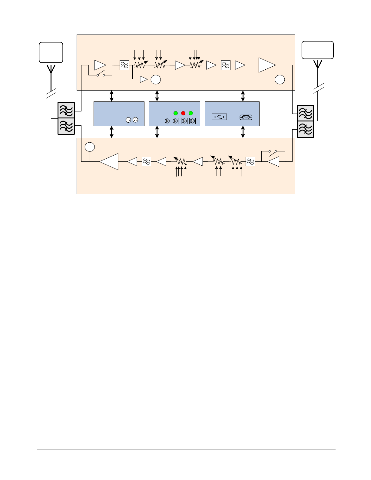
- The UHF Amplifier module contains a (Low Noise Amplifier) LNA designed to detect a very weak
signal. This stage is bypassed if the signal level at the input is higher than -20dBm
- The LNA is followed by an Automatic Gain Control (AGC). The AGC circuit measures composite
power level at the VGA input and adjusts the gain automatically, in order to maintain a constant signal
level at the VGA output delivered to the Power Amplifier (PA). Channel filters are inserted, in order to
reject adjacent channel signals and to improve the signal quality.
- The PA provides good performance for both linearity and efficiency. This amplifier has a heat sink
mounted to it. It has a high compression point and a high 3rd order Intercept point.
- The main AC input accepts 50/60 Hz with a 115 to 220 V AC power source. The Power Supply Unit
(PSU) converts AC to DC voltages to supply DC power to the amplifiers, monitoring and control units.
- The unit does not have a built-in UPS/Battery system. In case of inconsistency in the AC line power,
surge protection, short blackouts, high crossover time from the line AC to generator power, circuit
breaker for short circuit and overload protection, etc., an external UPS/Battery system is recommended.
- The amplifier is intended to be used in a BDA system that includes two duplexers; one at the BTS port
allowing the use for only one donor antenna for both UL and DL. The second duplexer is mounted at
the Service DAS antenna port. These duplexers provide at least 100 dB isolation at each end between
the two paths.
- A set of manual gain controls (MGC), ranging from 0 to 30 dB in 2 dB steps. Another set ranging from
0 to 15 dB in 1 dB steps are also added in the chain for additional attenuation if it is needed.
Page 5
U HF B I D I R E C T I O N A L A M P L I F I E R T E C H N I C A L M A N U A L
5
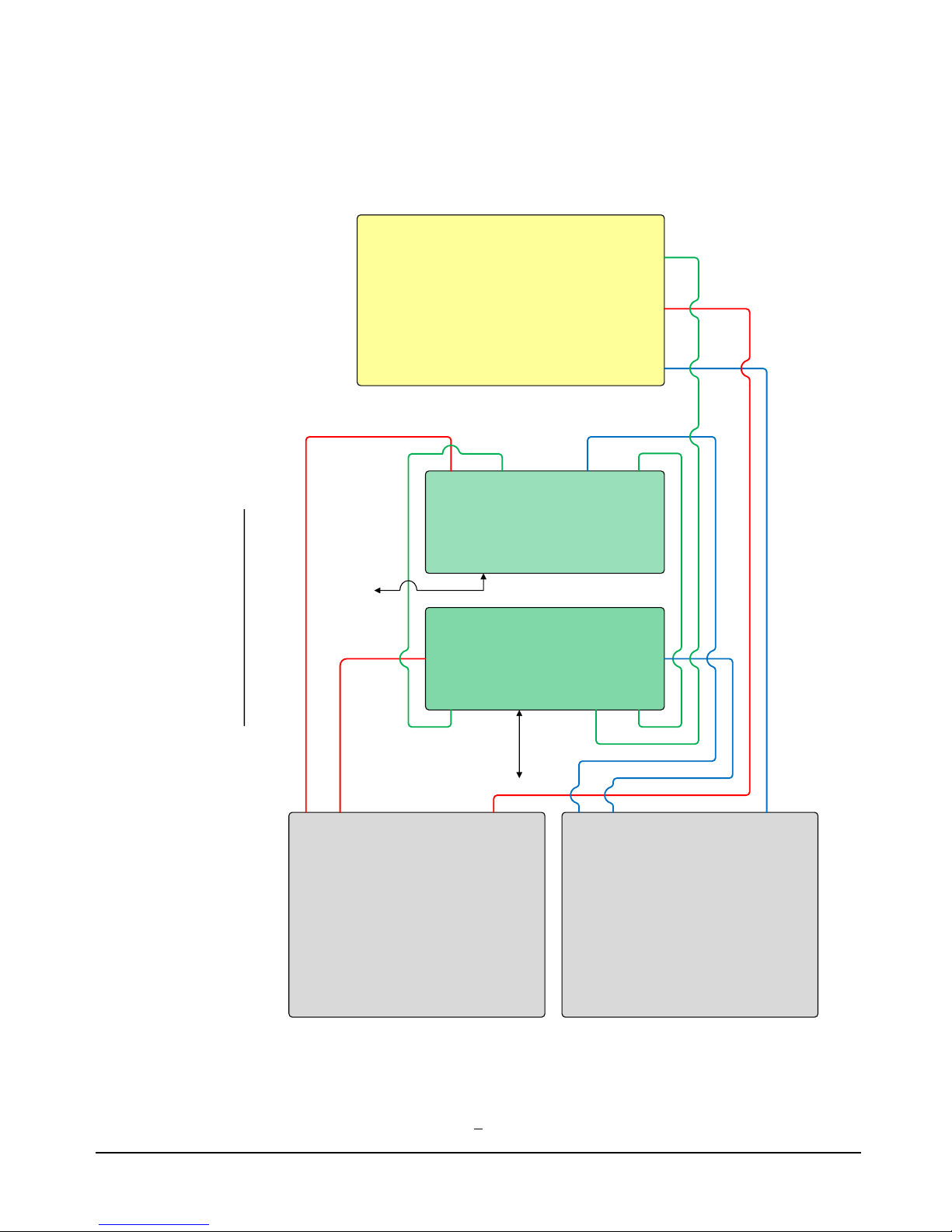
UDA LINK BLOCK DIAGRAM
RF_IN
RF_OUT
HPA_IN
HPA_OUT
SUB
CONTROL
PSU
RFM1
RFM2
SUB2 SUB1RS232PSU
MCU
RS232
RFM1 MCU1
SUB
RFM2 MCU2
RFM2
PSU
DC IN
RFM1 MCU
AC IN
MCU
RF_IN
RF_OUT
HPA_IN
HPA_OUT
SUB
UDA
#2
PSU
MCU
220VAC
UDA
#1
CONTROL
48VDC
Page 6
U HF B I D I R E C T I O N A L A M P L I F I E R T E C H N I C A L M A N U A L
6
Sub B’d Card
LED Alarms
MGC
HPA
DPLX
Power Supply (PSU)
DPLX
Donor
Antenna
(Base)
DAS Service
Antenna
(Mobile)
10,20,
..
1,2,3,..
Det
1,2,3,..
10,20,..
Monitoring & Control Unit
MGC ATT MGC ATT
MGC ATT
MGC ATT
HPA
LNA
LNA
AGC ATT
AGC ATT
AC
DC
Down Link Path
UP Link Path
RS 232USB (Optional)
Clk,Data,En
Det
Clk,Data,En
Det
Page 7
U HF B I D I R E C T I O N A L A M P L I F I E R T E C H N I C A L M A N U A L
7
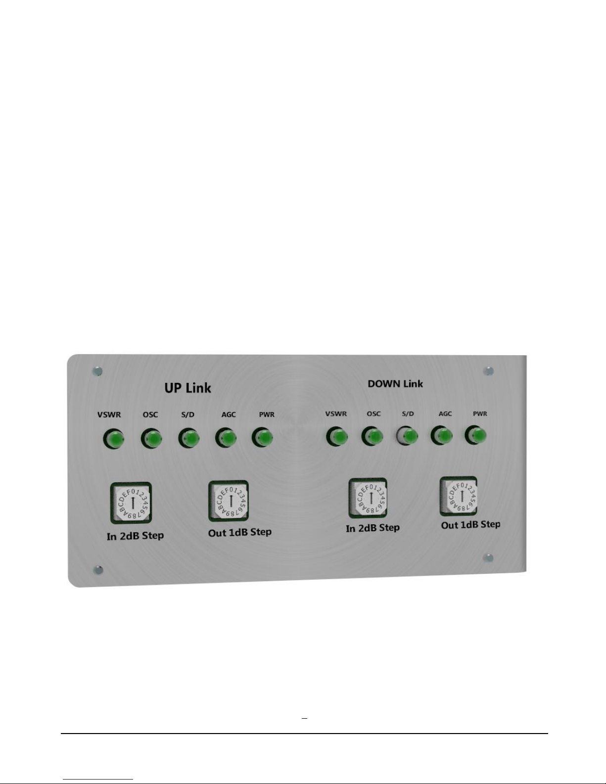
Led Indicator Alarm and Manual Level Control.
- The unit has visual alarms using LED indicators for the following conditions; AGC, S/D, OSC, power
and VSWR.
o AGC: alarm turns red when the AGC is not delivering any attenuation. This can happen in two
situations. Either the AGC is turned off by the user (see monitoring and control section) or if
the signal at input of the DL is too weak. This is not necessarily a failure. It can just be a warning
that the signal from the BTS is too weak.
o S/D: The shutdown indicator turns red when the system is in automatic shutdown. This happens
when the internal temperature is too high or when the output power exceeds the maximum limit
allowed. When the RF module is turned off by the user (see monitoring and control section)
the S/D indicator will start flashing.
o The Power indicator turns red when the RFM is not receiving the correct DC power.
o OSC indicator turns red when oscillation occurs in the system.
o VSWR indicator turns red when an antenna mismatch occurs in the system.
Page 8
U HF B I D I R E C T I O N A L A M P L I F I E R T E C H N I C A L M A N U A L
8
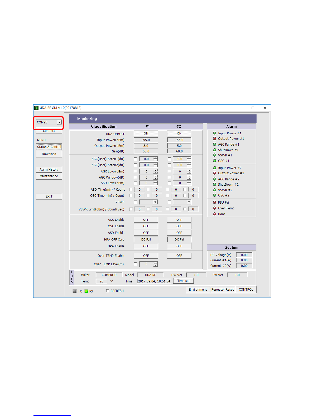
Monitoring and Control
The monitoring and control function is possible by connecting the BDA through a serial RS232 connector. A
Serial to USB adapter is available upon request.
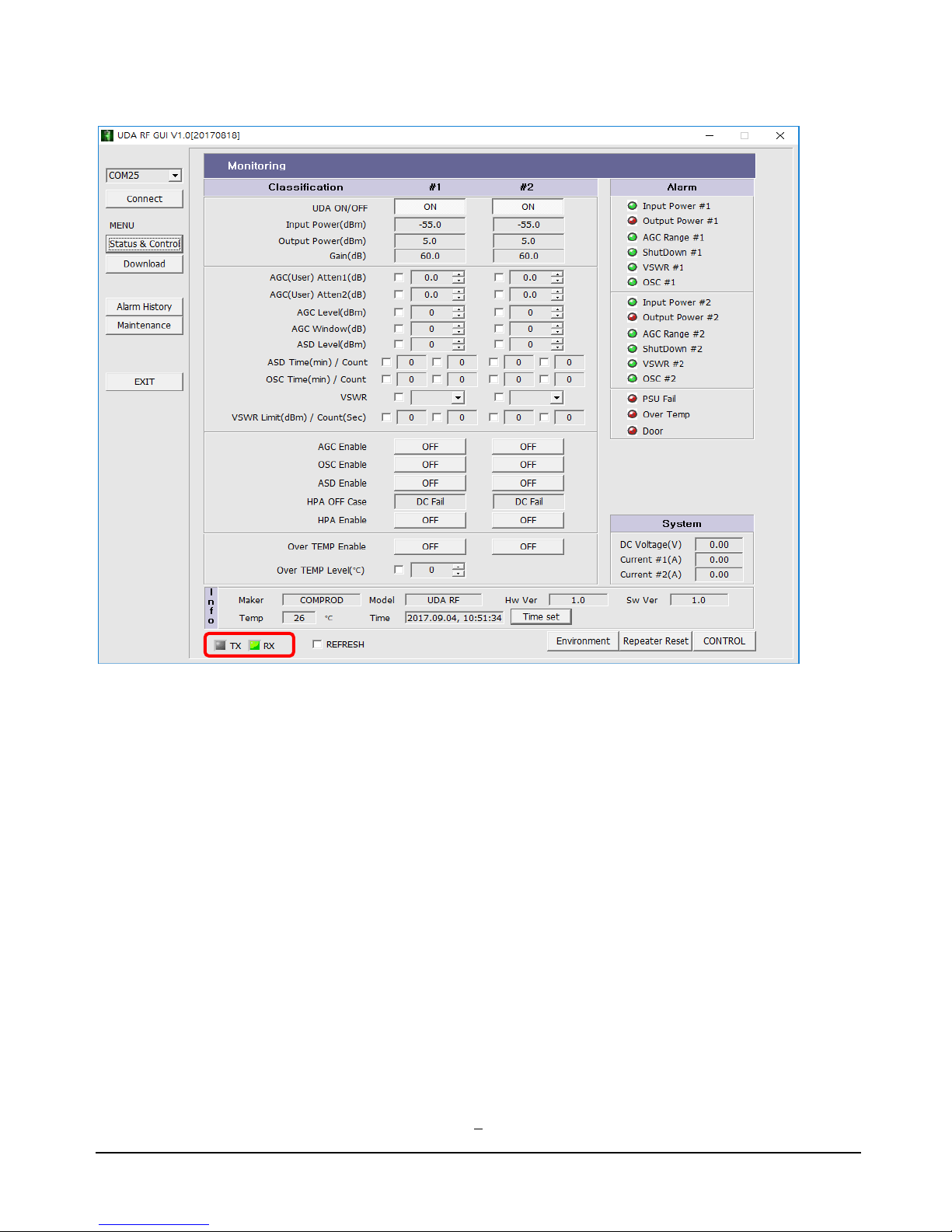
The software designed for this purpose is provided. This software should be installed on a computer with
Windows, XP, Vista,7, 8 or 10 versions. When you run the software, you will see the screen shown below.
Set the proper com port (1~99) or AUTO and press Connect (recommended).
Page 9
U HF B I D I R E C T I O N A L A M P L I F I E R T E C H N I C A L M A N U A L
9
When GUI connect to PC properly, TX, RX LED should be blinking and all parameters is displayed.
Page 10
U HF B I D I R E C T I O N A L A M P L I F I E R T E C H N I C A L M A N U A L
10
Status & Control
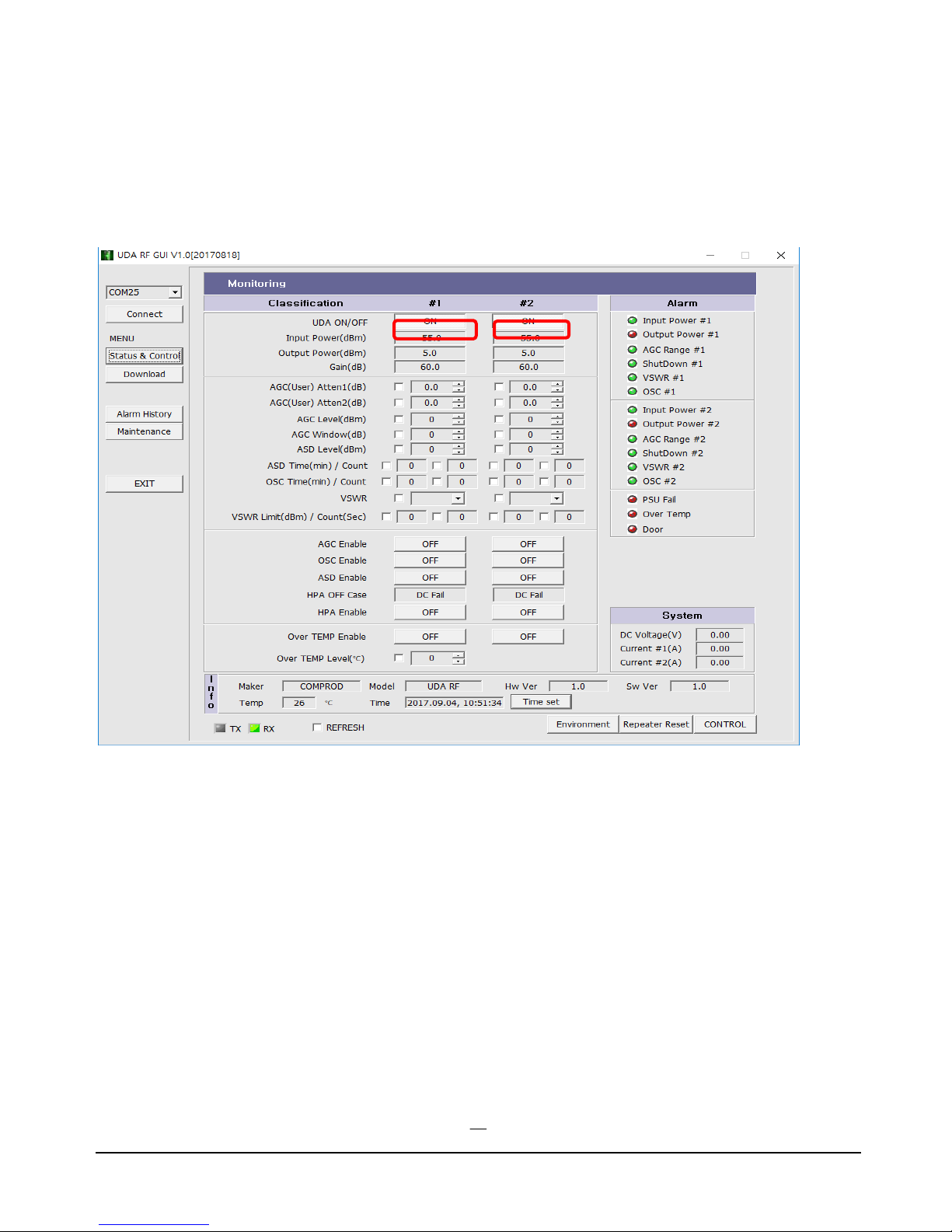
Status & Control menu consists of RF Control, PSU status, System Info, and Alarm status.
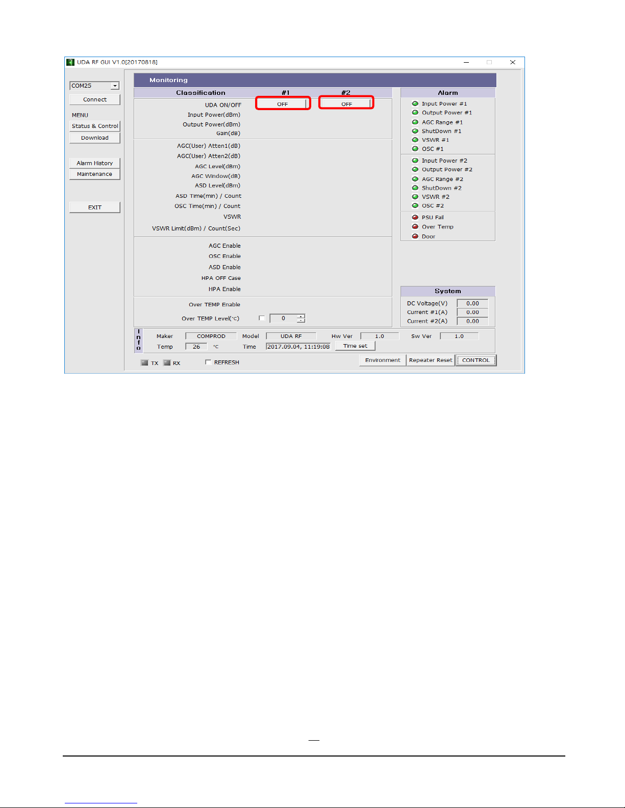
UDA ON/OFF: The MCU of UDA can control two UDA’s. If #1 is on and #2 is off, the parameters of #1 are
displayed and the parameters of #2 are hidden.
Page 11
U HF B I D I R E C T I O N A L A M P L I F I E R T E C H N I C A L M A N U A L
11
HPA Enable: When HPA Enable is turned off, the entire amplification chain turned off. In this case the
Shutdown alarm will flash indicating that the system has been shut down by the user.
AGC Enable: When AGC is enabled or ON, the attenuation in the AGC Atten window is determined
automatically by the system. If the AGC is off, the user can decide on the attenuation by changing the value.
OSC Enable: When OSC Enable is ON, the system is checking for oscillation caused by lack of isolation. If
the system detects oscillation The HPA is turned off automatically.
ASD Enable: When ASD is enabled, the system will shut down as soon as the output level reaches the value of
ASD Level.
Over TEMP Enable: When Over TEMP Enable is ON, the system will shut down as soon as the internal
temperature of the system exceeds Over TEMP Level.
VSWR Alarm: When output VSWR is over limit, a VSWR Alarm will occurred.
VSWR: The threshold of VSWR Alarm can be set to 3:1, 6:1 or 9:1.
VSWR Limit(dBm) / Count(Sec): When the output power is low, VSWR measuring is not accurate.
Limit(dBm) sets the output power limitation of VSWR measuring. When you set the limit to 28dBm, VSWR
Alarm will not occur below 28dBm output power even if the output port is opened. Count(Sec) is measuring
the time.
Page 12
U HF B I D I R E C T I O N A L A M P L I F I E R T E C H N I C A L M A N U A L
12
Alarm Definitions:
Input Power #1/#2: The signal from the antenna is too strong, or there is feedback from the internal to the
external antenna.
The system will continue to operate but the LNA will be bypassed."
Output Power #1/#2: The output power is exceeding 33 dBm. Turn on AGC or adjust the manual attenuators.
AGC Range #1/#2: The signal is exceeding the AGC range. Adjust the manual attenuators.
Shutdown #1/#2: The HPA is shut down see HPA OFF Case for the reason why.
VSWR #1/#2: Please check output port connections, cables and antennas to keep a good VSWR.
OSC #1/#2: Please check Isolation between the Donor and the Service antennas. Isolation should be greater
than System gain + 15dB.
PSU Fail: Power Supply Unit Failure.
Over Temp: Inside temperature exceeds the Over TEMP Level setting.
Door: The access door of the UDA is not properly closed.
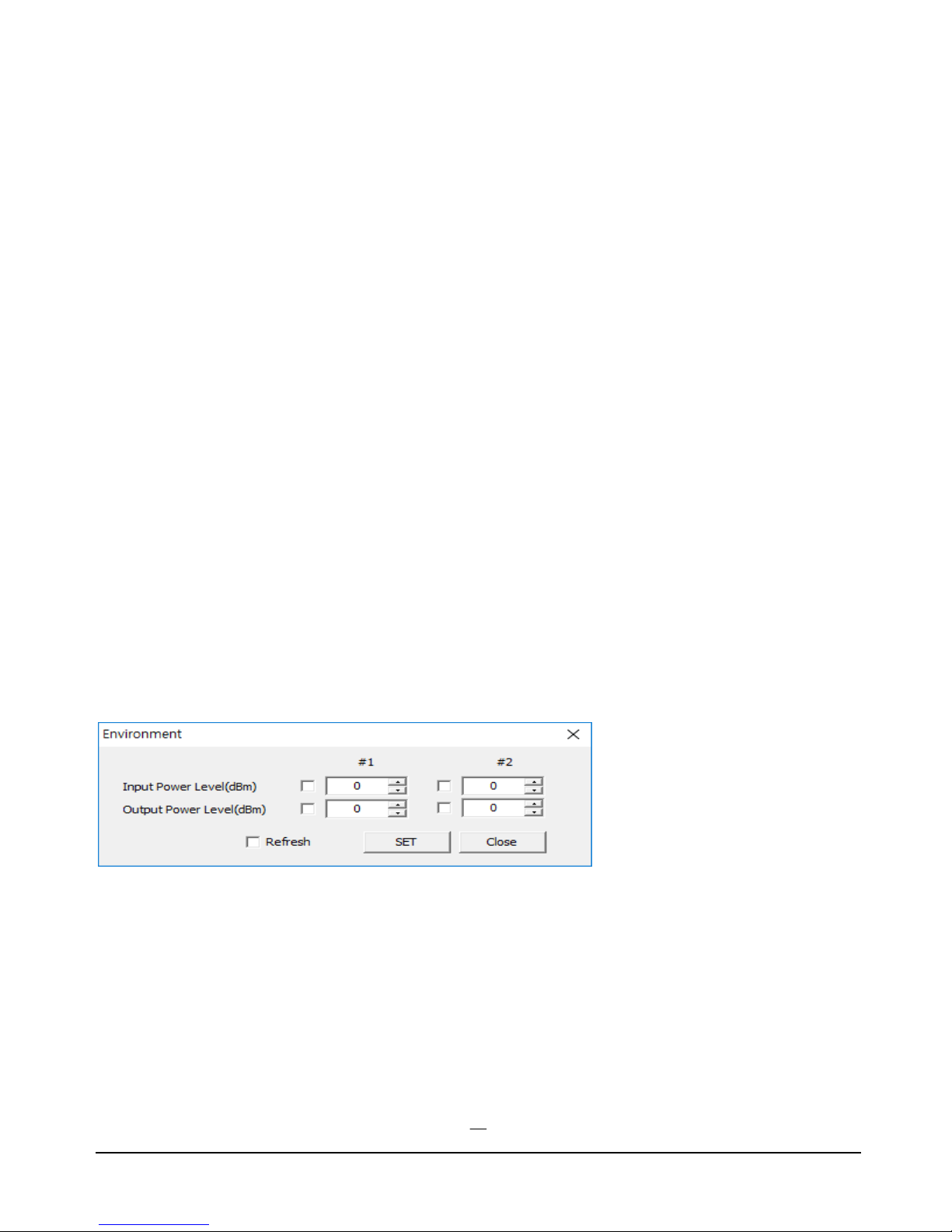
Environment.
Click on: Environment, opens up a smaller window, dragged to the right, reveals the UDA #1 and UDA#2
Power levels (Input and output).
Page 13
U HF B I D I R E C T I O N A L A M P L I F I E R T E C H N I C A L M A N U A L
13
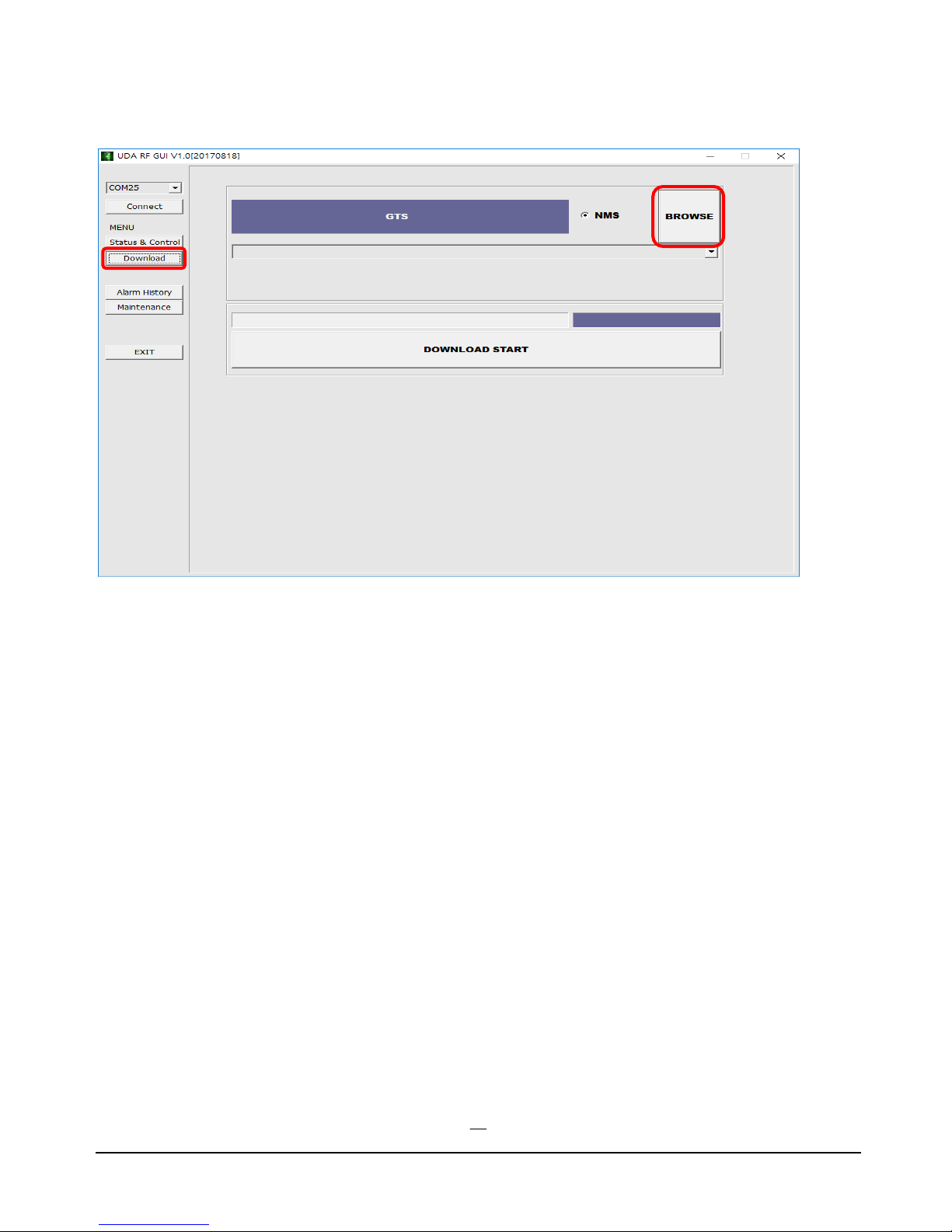
Firmware Download
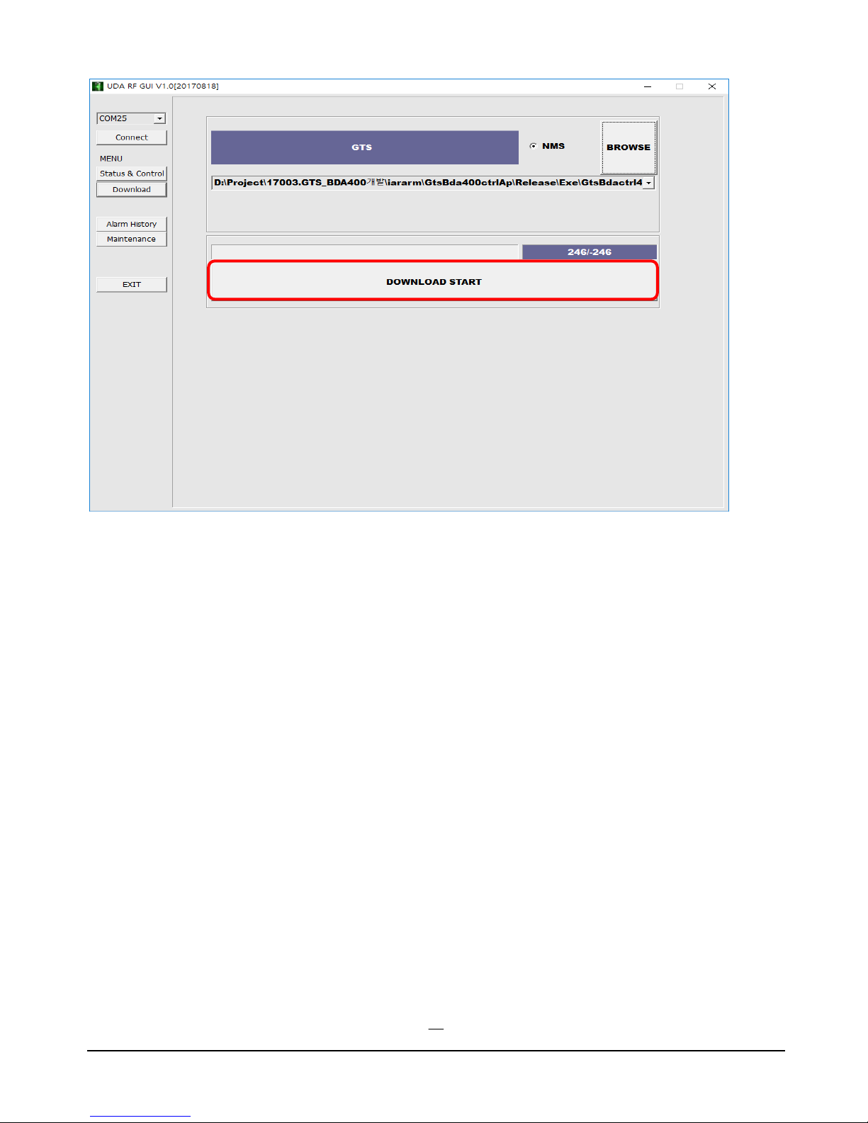
This is used to upgrade the firmware in the UDA.
Click on BROWSE, select the file and click on Open.
Click on DOWNLOAD START, download will proceed.
Page 14
U HF B I D I R E C T I O N A L A M P L I F I E R T E C H N I C A L M A N U A L
14
When download is finished properly “New Download Success!!!” message will pop up.
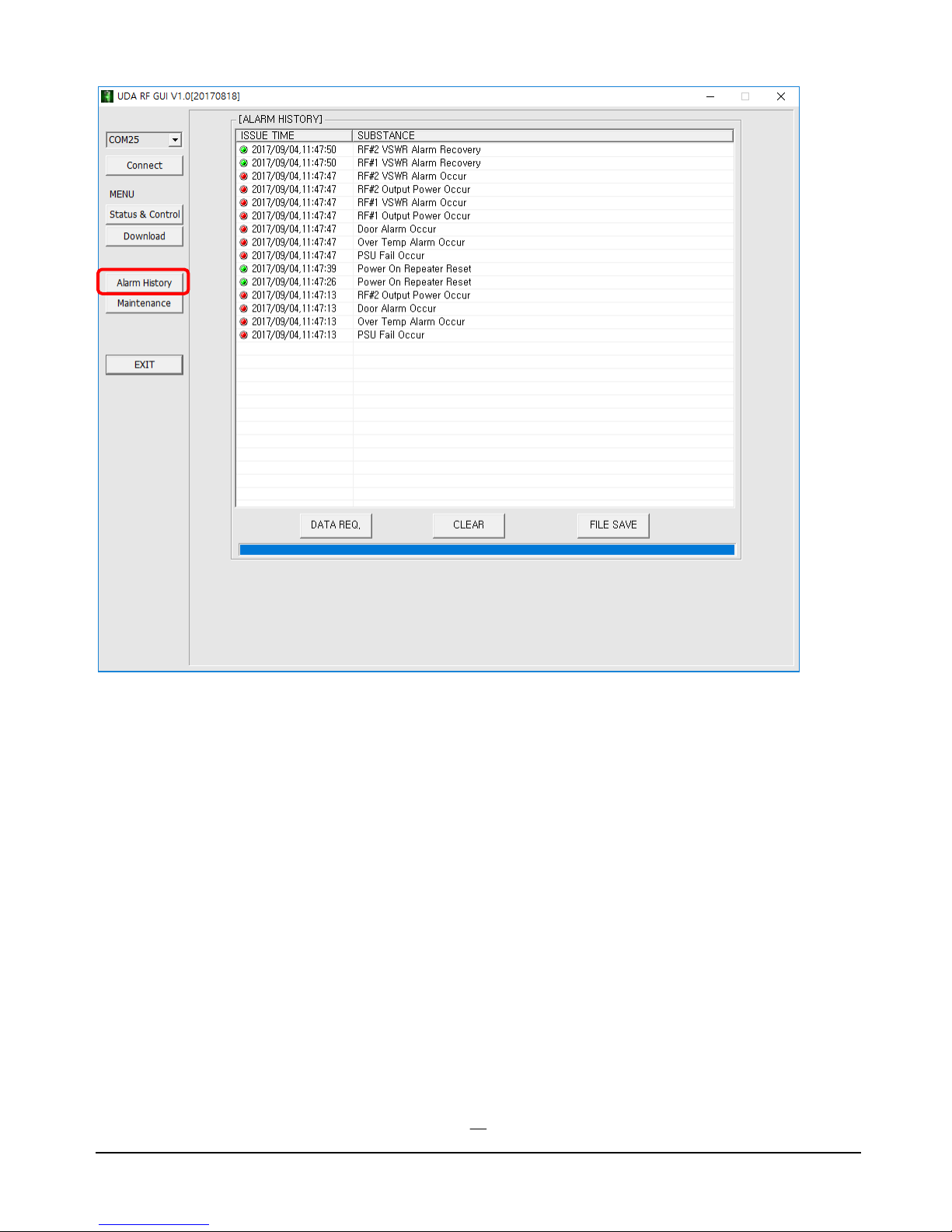
Alarm History
This is used to access the list of events that the UDA has recorded.
By clicking DATA REQ a list of events is relayed onto the screen.
Clicking on CLEAR, erases the entries.
By clicking FILE SAVE all data can be saved to a file.
Page 15
U HF B I D I R E C T I O N A L A M P L I F I E R T E C H N I C A L M A N U A L
15
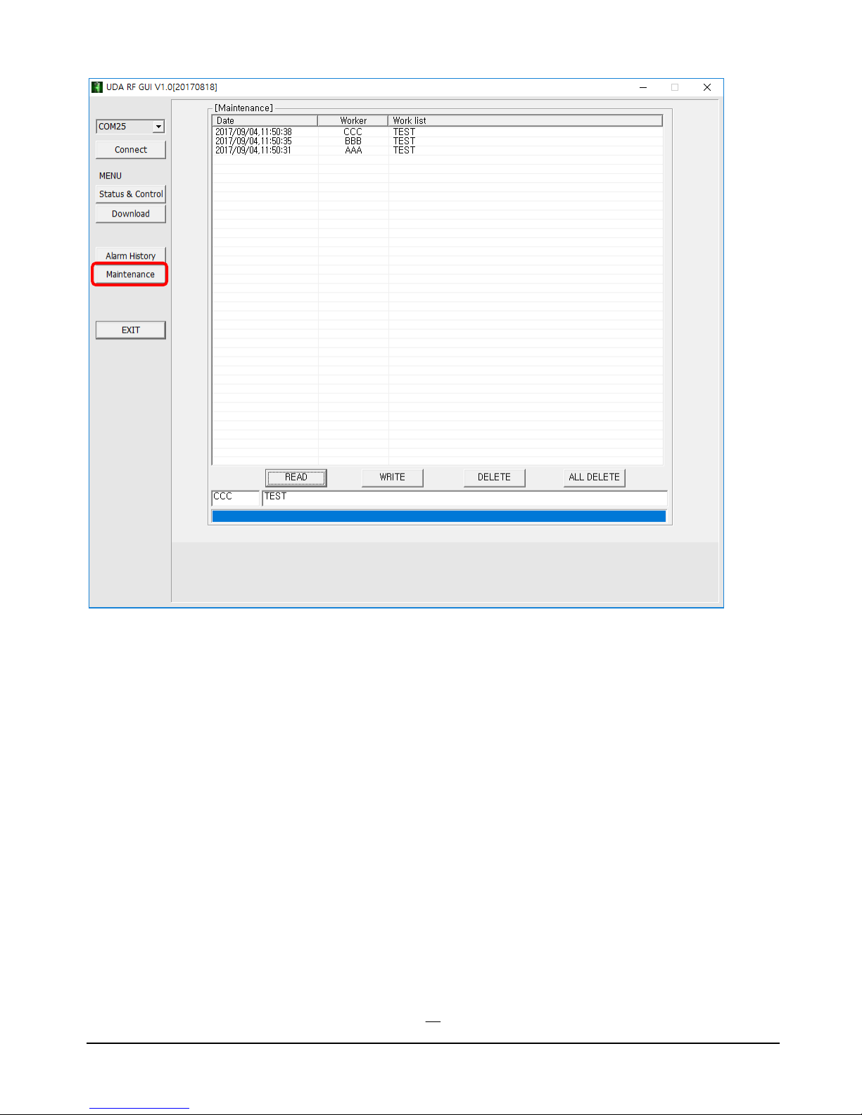
Maintenance
By clicking READ a working list is relayed onto the screen.
Clicking on WRITE, you can generate a working list that is shown in the window.
Page 16
U HF B I D I R E C T I O N A L A M P L I F I E R T E C H N I C A L M A N U A L
16
Page 17
U HF B I D I R E C T I O N A L A M P L I F I E R T E C H N I C A L M A N U A L
17
1 2 3
4
5 6 7
8
9
10 11 12 13
14
15
16
UL
DL
1 2 3
4
5 6 7
8
9
10 11 12 13
14
15
16
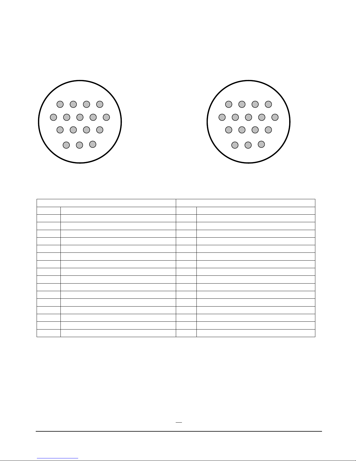
UL Dry Contact Alarm connection
DL Dry Contact Alarm connection
PIN
Description
PIN
Description
1
NC DC Relay
1
NC DC Relay
2
COM DC Relay
2
COM DC Relay
3
NO DC Relay
3
NO DC Relay
4
NC Oscillation
4
NC Oscillation
5
COM Oscillation
5
COM Oscillation
6
NO Oscillation
6
NO Oscillation
7
NC RF System Failure Relay
7
NC RF System Failure Relay
8
COM RF System Failure Relay
8
COM RF System Failure Relay
9
NO RF System Failure Relay
9
NO RF System Failure Relay
10
NC AC Relay
10
NC AC Relay
11
COM AC Relay
11
COM AC Relay
12
NO AC Relay
12
NO AC Relay
13 13
14
NC VSWR Donor Antenna
14
NC VSWR Donor Antenna
15
COM VSWR Donor Antenna
15
COM VSWR Donor Antenna
16
NO VSWR Donor Antenna
16
NO VSWR Donor Antenna
Dry Contact Alarms
Each BDA has two 16 PIN Female connectors for Dry Contact Alarms. Male connectors, with labeled wires,
are also supplied with the unit for easy connection.
Page 18
U HF B I D I R E C T I O N A L A M P L I F I E R T E C H N I C A L M A N U A L
18
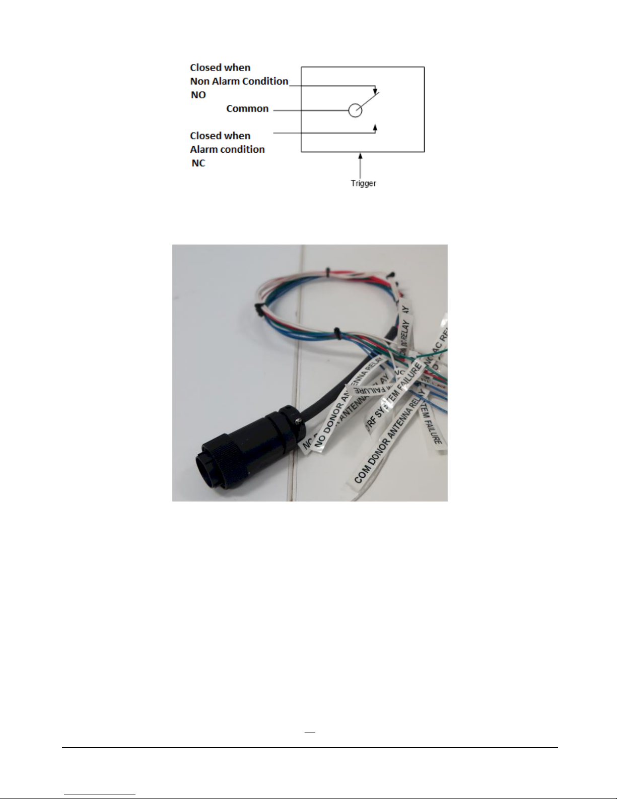
Relay Shown in Non-alarm Condition
Connector kit with labeled wires supplied with the unit.
Unpacking
1) If the shipping box is damaged, do not open it, take a picture and contact the freight carrier for a claim.
2) If the shipping box is not damaged, the UHF BDA should be unpacked soon after delivery and
carefully inspected for possible shipping damage. It is the customer’s responsibility to file claims with
the freight carrier if damage is suspected and that is usually limited to a certain time period after
delivery.
3) Carefully compare the packing slip(s) against the package contents to verify the receipt of all expected
items.
4) Retain all product documentation and make sure that manuals are forwarded to the appropriate site
management, installation and service personnel.
Page 19

U HF B I D I R E C T I O N A L A M P L I F I E R T E C H N I C A L M A N U A L
19
Lightning Protection
Although relatively rugged, lightning can damage the internal working mechanisms inside the BDA.
We recommend the installation of a lightning surge suppressor in the transmission line where it enters
the building prior to the BDA. The suppressor should be grounded to the building ground bus at the
transmission line entry point. Choose a suppressor that will handle the expected amount of input power
from the BDA to the donor antenna.
Antenna Installation
Buildings that are not designed or upgraded for antenna systems need special attention for antenna mounting,
equipment installation and cable runs. There are many variables involved in the design of a DAS system
(distributed antenna system).
There are structural requirements for the location of the outdoor antenna (Donor); masts, towers, building
structure for handling wind and ice loading.
-Protection of antennas and cables from building occupants and general human interaction.
- Installers/designers must be aware of general seating, foot traffic areas and different access points.
- All Antennas must be designed for the working frequency, and ensure they meet the exposure
requirements.
- The donor antenna and distribution antennas must have 12 dB + the Maximum gain of the amplifier of
isolation between them. Less isolation will cause the module to overload and oscillation will occur which may
result in damage to the amplification module.
- Antennas should be mounted following the manufacture’s guidelines for RF connection and be affixed to the
building at the location of the desired signal.
- All cables used in the DAS system shall be 50 Ohms and clamped properly to ensure the cables 50 Ohm
impedance characteristics. Improper clamps will change the impedance of the cable at that location thus
changing the efficiency of the system.
- Antenna placement through the DAS system is important to produce a balanced, distributed signal. The use
of correct decouplers, power dividers, and signal taps is important to promote a balanced system.
Page 20

U HF B I D I R E C T I O N A L A M P L I F I E R T E C H N I C A L M A N U A L
20
BDA Installation
DO NOT APPLY A.C. POWER TO THE BDA UNTIL CABLES ARE CONNECTED TO
BOTH PORTS OF THE BDA AND THE ANTENNAS.
1. Mount the BDA on the wall with the RF connectors pointing DOWN. Using appropriate screws and
anchors, attach the BDA to the wall using the four mounting holes on the side flanges.
2. Ensure that the isolation between the donor antenna and the service antenna is at least 12 dB greater than the
BDA gain. (Use the higher of the Uplink and Downlink gains reported on the BDA test data sheet).
3. Connect the cable from the donor antenna to the BDA connector labeled “BASE” and the cable from the
service antennas to the BDA connector labeled “MOBILE”.
4. Open the door of the enclosure of the BDA and verify that both of the PSU switches are in their factory pre-
set “ON” positions. Close the panels.
5. Connect the AC power cord to the BDA and then to the power source. Verify that the “Power ON” lamp is
illuminated.
6. Connect the computer with the software installed via RS 232 serial connector or via a USB port with a USB
to serial adapter.
7. On the RF_BDA_GUI make sure that AGC Enable, ASD Enable and HPA Enable functions are all turned
ON.
Installation of the BDA is now complete. To adjust the gain controls to suit the specific signal environment,
refer to the section on Monitoring and Control.
Page 21
U HF B I D I R E C T I O N A L A M P L I F I E R T E C H N I C A L M A N U A L
21
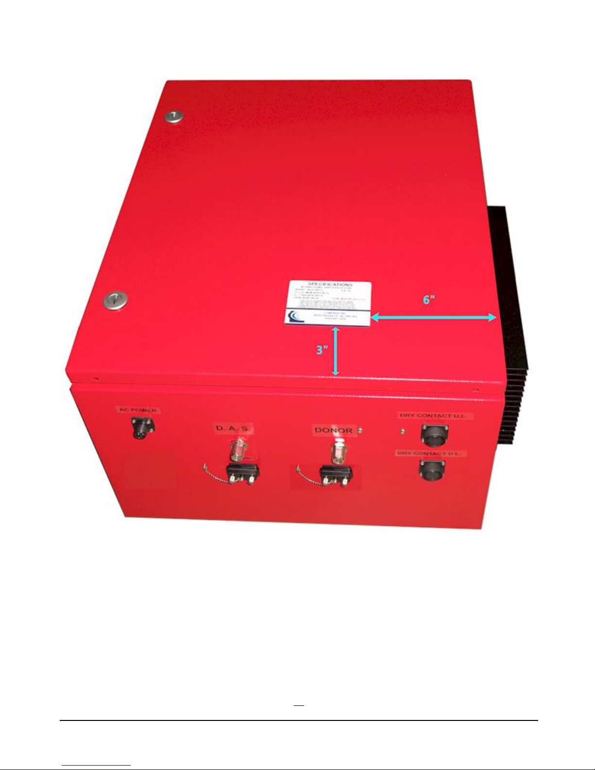
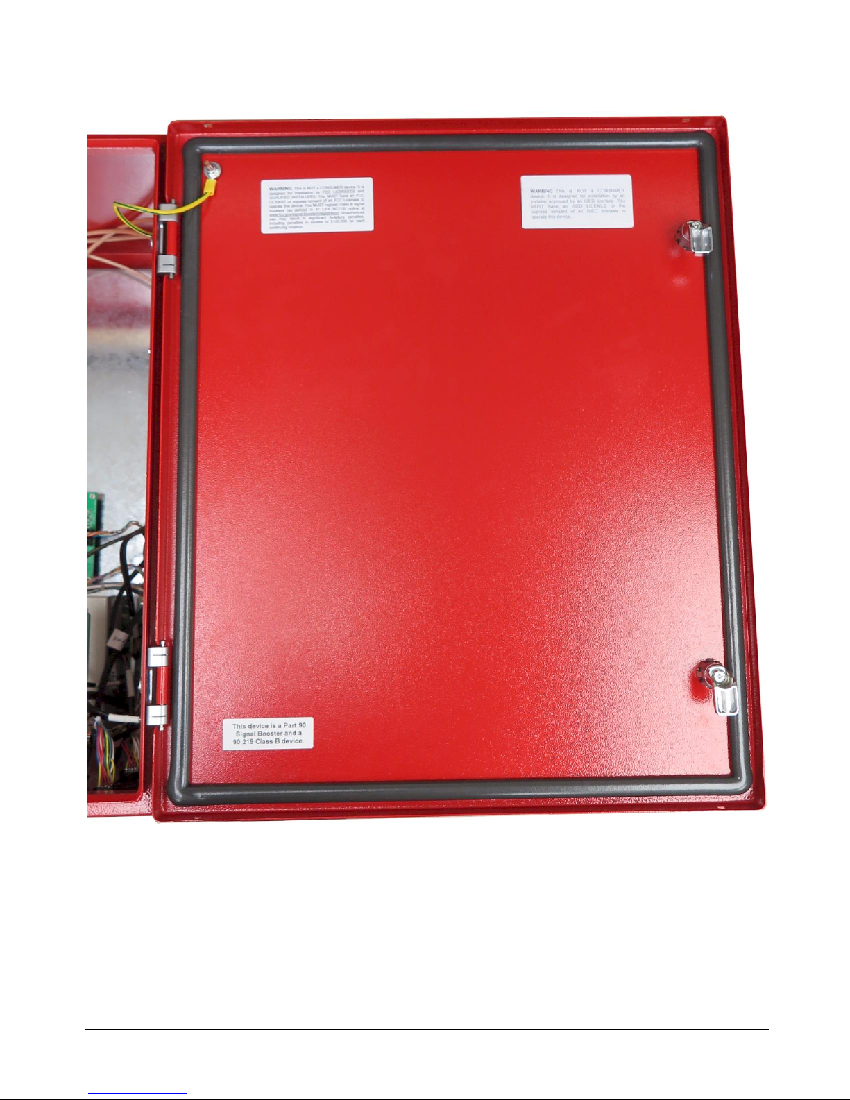
The amplifier unit has its FCC/IC, warning and Signal Booster Class B labels on the front cover, as shown in
the above picture. These labels must not be removed.
Label position on the BDA
Page 22
U HF B I D I R E C T I O N A L A M P L I F I E R T E C H N I C A L M A N U A L
22
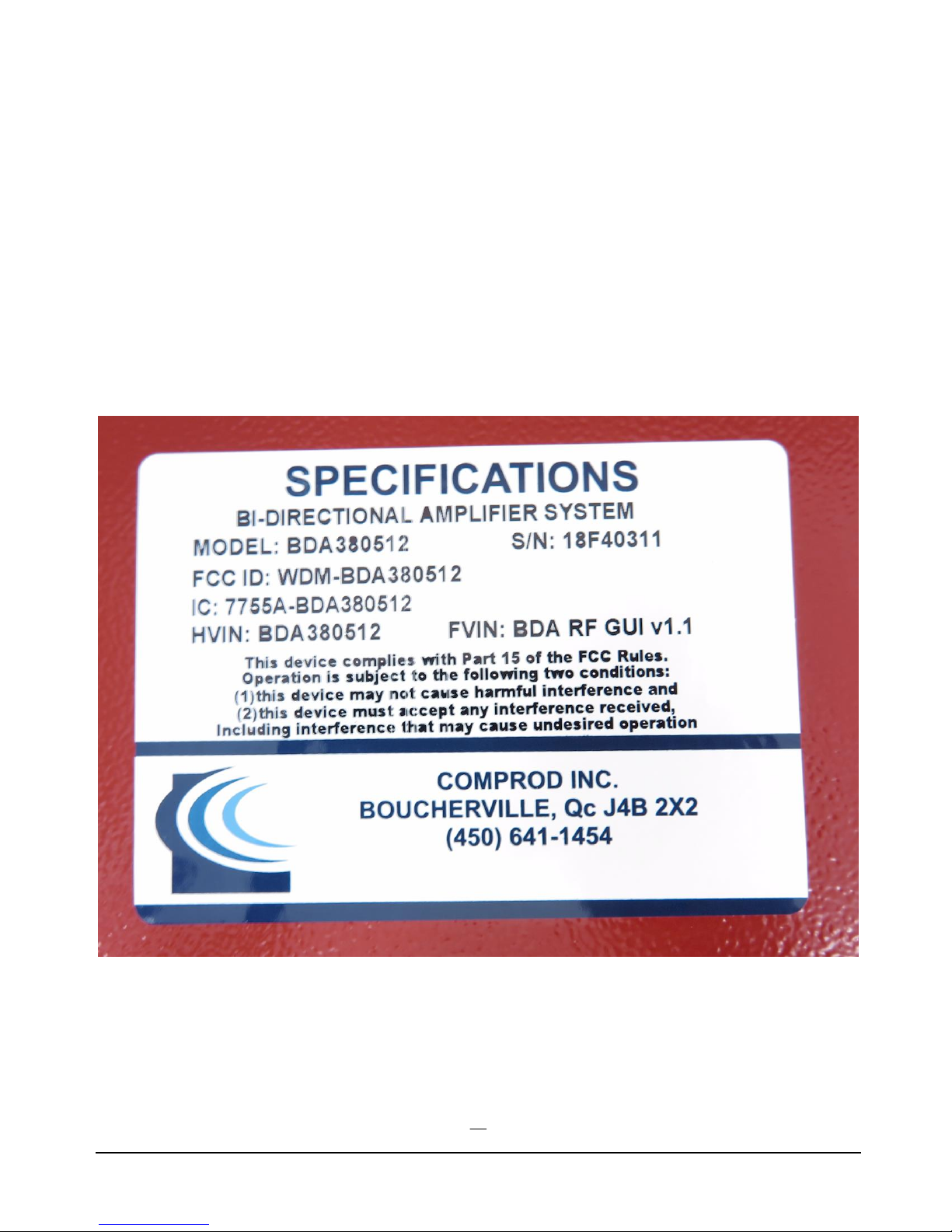
The label on the enclosure as indicated should have the following text:
Model: BDA380512
FCC ID: WDM-BDA380512
Model: BDA380512
IC: 7755A-BDA380512
HVIN: BDA380512 FVIN: BDA RF GUI V2.0
Page 23
U HF B I D I R E C T I O N A L A M P L I F I E R T E C H N I C A L M A N U A L
23
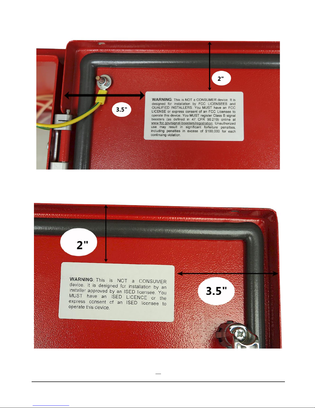
Additional labels on the BDA.
Page 24
U HF B I D I R E C T I O N A L A M P L I F I E R T E C H N I C A L M A N U A L
24
Warning if the unit is destinated to US market
Warning if the unit is destinated to Canadian market
Page 25
U HF B I D I R E C T I O N A L A M P L I F I E R T E C H N I C A L M A N U A L
25
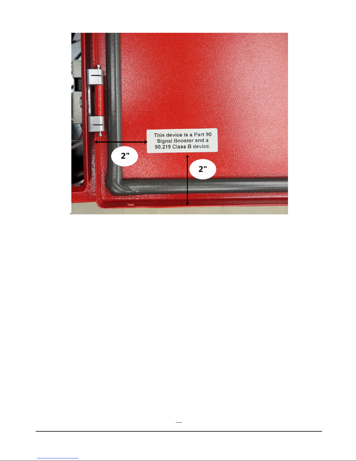
Additional label
Page 26
U HF B I D I R E C T I O N A L A M P L I F I E R T E C H N I C A L M A N U A L
26
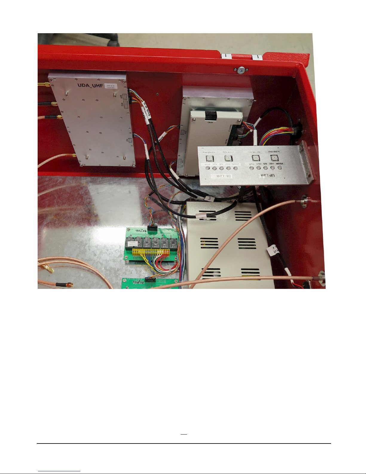
UHF Bidirectional Amplifier
Page 27

U HF B I D I R E C T I O N A L A M P L I F I E R T E C H N I C A L M A N U A L
27
Warnings and Notices
WARNING: Changes or modifications not expressly approved by Comprod Communications
could void the user’s authority to operate the equipment.
WARNING: Service antenna should have 2.15 dBi (0dBd) Gain Max.
WARNING: To satisfy RF exposure requirement,the RF exposure safe separation distance is
38cm
Notice:
This equipment has been tested and found to comply with the limits for a Class A digital device,
pursuant to Part 15 of the FCC Rules. These limits are designed to provide reasonable protection
against harmful interference when the equipment is operated in a commercial environment. This
equipment generates, uses, and can radiate radio frequency energy and, if not installed and used in
accordance with the instruction manual, may cause harmful interference to radio communications.
Operation of this equipment in a residential area is likely to cause harmful interference in which
case the user will be required to correct the interference at his own expense.
This device has been designed to operate with the antennas having impedance of 50 ohms. The use of
high gain antennas exceeding the values specified by the manufacturer is strictly prohibited.
FCC link for Part 90 Class B Signal Booster Registration & Discovery:
https://signalboosters.fcc.gov/signal-boosters/
Page 28

U HF B I D I R E C T I O N A L A M P L I F I E R T E C H N I C A L M A N U A L
28
Definition of Terms:
AGC – Automatic Gain Control
ASD – Automatic Shut Down
Attenuate – Reduce sensitivity or gain
BDA – Bi-Directional Amplifier
BPF – Bandpass Filter
BTS – Base Transceiver Station
DAS – Distributed Antenna System
DL – Downlink – The signal coming down into a building from a remote tower via a “Donor” antenna.
HPA (or PA) – High Power Amplifier
LNA – Low Noise Amplifier
MCU – Master Control Unit
MGC – Manual Gain Control
OSC – Oscillate – When the donor antenna signal gets back into the DAS, oscillation will occur. Hence there
must be isolation between the donor antenna and the DAS system. A directional donor antenna is important in
preventing oscillation.
Over temp – When the internal temperature reaches a pre-set limit.
RFM – Radio Frequency Module
S/D – Shut down
SMA – Sub Miniature [Coaxial Connector] version A
PSU – Power Supply Unit
UL – Uplink – The signal being sent up to a remote tower from a DAS
V.S.W.R. - Voltage Standing Wave Ratio – Measurement of the efficiency of an RF system.
End of Document
 Loading...