

Portable
Model
Field
2100M
Dental
Unit
Operation
And
Maintenance
Manual
Compressor
7002
South
Englewood
Technologies,
Revere
(303)
Parkway,
Colorado
799-8177
80112
1-800-847-0694
USA
LTD.
Unit
90
TABLE
OF
CONTENTS
age
hg
U
WU
LI)
A
UU
DIA
Section
General
Customer
Description
Principals
Performance
Equipment
Service
Of
Of
Characteristics
Not
Specification,
Limited
Safety
Delivery
Waste
Water
Compressor
Preparation
System
Waste
Fresh
System
Cleaning
Warranty
Precautions
Unit
Container
Container
Unit
For
Shut
Down
Container
Water
Flush
Purging
Procedures
Repacking
Storage
Equipment
General
Testing
Care
Service
Equipment
Maintenance
Water
Air
Air/Water
Three
Daily
Basic
Maintenance
Parts
Filter
Intake
Filter
Regulators
way
Syringe
Functional
Troubleshooting
And
Lists
Diagrams
System
Operation
Provided
Capacities
Setup
Connections
Setup
Use
And
Inspection
Information
And
Tools
Checklist
Guide
Storage
And
Technical
Required
and
Maintenance
Inspection
Data
Schedule
Record
SECTION
1
INTRODUCTION
1.1
The
set-up,
repair
All
maintain
review
and
12
In
please
speak
Representatives.
am.
Monday
13
The
contained
unit
system
provides
driven
a
handpiece,
three
evacuator.
water
irrigation
liquids
The
standard
GENERAL.
information
operation,
of
the
authorized
or
this
manual.
maintained
CUSTOMER
the
event
you require
call
1(800)
with
to
5:00
through
DESCRIPTION
Model
Midwest
2100M
portable
designed
includes
power
vacuum
Tradition L fiber
Midwest
way
syringe,
The
supply
and a waste
and
debris
system
electrical
contained
Model
service
by
one
p.m.,
Friday
for
to
system.
system
for
contains
in
this
maintenance,
2100M
personnel
the
The
trained
445-8765
of
Our
Field
dental
field
an
the
Rhino
saliva
handpiece
from
connections
Field
who
Field
Unit
system should
personnel
SERVICE.
assistance
or
our
service
Mountain
oilless
dental
all
hours
excluding
OF
SYSTEM.
Unit
is a light-weight,
operating
or
operatory
air
instruments
The
delivery
low
ejector
contains a self-contained
container
the
evacuation
necessary
manual
troubleshooting
(303)
Customer
Standard
compressor
optic
speed
and
coolant and
for
covers
Unit.
either
should
with
carefully
be
operated
only.
this
operate,
system,
790-2000
Service
are
from
holidays.
and
treatment
use.
and
unit
supports
high
handpiece,
high
volume
collection
and
and
8:00
Time,
self-
The
that
air-
speed
oral
system.
tubings
for
operation.
and
the
of
13.1
Module
system
The
cylinder
wall
The
115V/60Hz
system
to
compressed
Features:
*
+
*
+
-
*
+
+
*
132
contains a fold
instrumentation
instrument
Bandpieees,
reservoir
system
contains
the
Ejector.
waste
Compressor
consists
that
provides > 3.8
compressor
piston
and
teflon
1%
HP
or
is
air-cooled
reduce
Fan
1%
horsepower
Aluminum,
coated
Coiled
Pressure
(1)
10
cord
(1) 10
Grounding
Rotationally
storage
removable
for
High
the
air.
induced
oilless
cylinder
compressed
switch
foot
hospital
(115Vac/60Hz)
foot
CEE-7
cable
case
end
Delivery
tray.
control
with
high
the
an
air
Volume
The
Vacuum
container
Module:
of
1%
HP
consists
that
utilizes a teflon
ring
piston
electrical
230V/50Hz
and
incorporates
operating
air
cooled
system
electric
compressor
wall
and
air
aftercooler
and
unloader
grade
cord
molded,
with
out
and
regulators
operated
with
polyethylene
recessed
caps
Unit
Module:
control
provides a work
The
delivery
blocks,
and-afiber~eptictighting
handpiece,
speed
vacuum
Evacuator
system
automatic
The
Compressor
oilless
air
compressor
scfm
of
free
air
at
40
of a reciprocating,
coated
for
lube-free
motor
motor
(230Vac/50Hz)
unit
operates
electrical
temperature
pump
teflon
piston
system
NEMA
hardware
The
for
placement
unit
water
supply,
system
(HVE)
includes a removable
overflow
cylinder
operation.
from
supply.
an
after-cooler
of
with
teflon
ring
5-15
electrical
carrying,
and
delivery
of
surface
for
contains
and
an
unit
The
to
power
and
Saliva
protection.
psi.
one
a
The
the
unit
the
the
the
air
also
The
entire
repacked
for
only
structural
into
safe
transportation
act
to
housing
unit
can
two
rotationally
protect
the
for
be
quickly
and
system
the
unit.
disassembled
molded
storage.
but
carrying
The
also
and
cases
cases
not
provide
the
Features:
+
Autoclavable
*
Two
handpiece
+
Fwo
straight
Midwest
+
Aseptic
*
Variable
coolant
Three-way
removable,
+
Pressurized
water
+
Water
*
Water
*
Individual
each
*
Individual
air,
-
Repair
*
High
with
*
Saliva
straight
+
Air
- 6 foot
*
Waste
shutoff
+
(1) 10
cord (115
*
(1)
-
Rotationally
storage
14
141
connectors
non-retraction
speed
water
filter
coolant
flush
drive
handpiece
pressure
water,
kit
volume
straight
ejector
tubing
driven
vacuum
suction
container
foot
10
foot
CEE-7
case
PRINCIPALS
AIR
COMPRESSOR
stainless
control
ascpsis
syringe
autoclavable
water
system
vacuum
evacuator
tubing
control
disc
switch
with
container
flow
control
air
pressure
gauges
and
pump
handpiece
type
exhaust
with
automatic
hospital
Vac/60
grade
Hz)
cord
molded,
with
polyethylene
recessed
OF
steel,
instrument
system
tubings
water
coolant
foot
control
coiled
tubing
tip
with
35
Micron
for
eaelf
handpieces,
adjustment
for
handpiece
air
tank
control
(autoclavable)
vent
(230
(autoclavable)
with
tubing
overflow
NEMA-S15
Vac/50Hz)
carrying,
hardware
OPERATION.
MODULE.
tray
with
with
and
for
drive
electrical
142
A
dissipation
thermodynamics
energy
the
extreme
gas.
The
systems
a)
module
the
electric
b)
coiled
exhaust
cooling
lower
level
removal
acceptable
143
The
switch
off
pressure.
air
turns
again
COOLING
special
operating
of
dictates
energy
Fan
case
Aftercooler - The
and
air
as
pressure
will
rise
in
compressor
for
dissipation
Induced
employs
housing
motor.
tubing
the
that
needed
off
under
that
valve
to
air.
The
temperature
to
assist
of
moisture
dry
PRESSURE
UNLOADER.
compressor
automatically
to
An
unloader
against
to
prevent
load.
SYSTEMS.
problem
heat
generated. A basic
and
that
if a
be
concentrated
the
temperature
system
Cooling - The
fans
to
cool
compressed
is
dissipate
aftercooler
in
the
operating
maintain
the
the
with
the
law
fluid
employs
of
heat.
that
blow
the
compressor
placed
immediately
heat
serves
of
the
condensing
from
the
air.
SWITCH
module
turns
the
is
placed
piston
motor
compressors
of
conservation
(air)
is
resulting
of
the
two
air
ambient
air
is
cooled
to
the
to
substantially
air
to
an
and
air
to
includes a pressure
the
system
required
to
eliminate
whenever
from
having
is
the
law
of
of
compressed,
in
an
compressed
cooling
compressor
air
through
pump
and
using
after the
surrounding
operating
subsequent
achieve
an
AND
on
and
operating
back
the
unit
to
start
Air
Compressor
is
powered
reciprocating
moves
downstroke,
muffler.
upstroke
intake valves
through
hose
The
teflon
for
an
by a 1%
piston.
up
and
air
The
exhaust
of
the
close
the
exhaust
to
the
delivery
compressor
coated
cylinder
external
Pump:
down
is
pump
lubricant.
The
HP
electric
To
in
drawn
valve
piston,
and
compressed
valve
unit.
uses a teflon
sleeve
in
air
and
air
compressor
motor
compress
the
cylinder.
through
remains
is
compressed.
then
to
eliminate
that
drives
air,
the
On
the
air
closed.
air
is
forced
through
ring
piston
the
pump
piston
the
intake
On
the
The
out
the
air
and
need
a
144
Compressor
stored
used.
through
air
filters
compressed
1.4.4.1
used
of
DELIVE
in
an
Air
the
pressure
out
any
Handpiece
by
the
the
handpiece
is
handpieces
Compressed
handpiece
while
to
drilling.
air
is
taken
air
tank
at a pressure
taken
from
Air/Filter
desired
the
to
remaining
air.
Operation:
to
that
rapidly
air
is
also
provide
additional
IT
MOD
in
by
the
delivery
the
air
tank
Regulators
operating
moisture
drive
released
droplets
Compressed
turbines
spin
by
cooling
o
of
100
that
the
cutting
the
of
unit
psi
and
routed
reduce
levels
from
air
in
the
head
of
tooth
the
and
until
the
and
the
is
head
bur.
the
1.4.42
pressurized
water
syringe,
the
Water
by
pressure
water
handpiece
System - The
the
compressed
necessary
coolant
flush
for
spray
system.
fresh
water
air
to
operation
for
the
handpieces
system
provide
of
three
is
the
way
and
1.443
evacuation
powered
is
used
which
surrounding
The
debris
collection
the
1.4.4.4
an
automatic
automatic
a
second
15
The
with
1500
The
Evacuation
system
by
compressed
to
accelerate
creates a negative
it.
vacuum
created
through
container
liquid
and
Drain
drain
system
when
PERFORMANCE
system
the
operates
maximum
Watts.
system
is
environmental
System - Suction
is
created
air.
the
is
used
the
HVE
and
which
solids.
System - The
as
well
will
drain
the
compressor
on
115/230
power
able
to
perform
conditions.
for
using a (venturi)
The
venturi
speed
of
pressure
to
pull
Saliva
Ejector
separates
delivery
as a manual
the
air
tank
cycle
the
air
or
air,
liquids
the
air
module
drain.
for
starts.
principle
stream
vacuum
into
1/10
CHARACTERISTICS.
Vac/50/60
requirement
under
less
the
following
the
pump
and
the
from
has
The
of
Hz
than
a
Temperature:
Altitude:
Humidity:
1.6
1)
2)
3)
EQUIPMENT
Electrical
Consumables
a)
Oral
b)
Saliva
Handpieces
30°
to
120°
©)
0
to
8,500
Feet
above
sea
level
0
to
95%
relative
NOT
Power
Evacuation
Source
which
Ejector
Mouthpiece
Fahrenheit
(0 to
(-2°
2,591
humidity
PROVIDED.
include:
Tip
to
49°
meters)
17
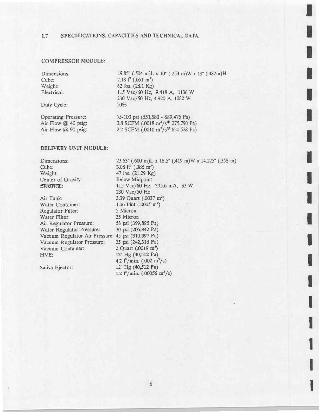
SPECIFICATIONS,
CAPACITIES
AND
TECHNICAL
DATA.
COMPRESSOR
Dimensions:
Cube:
Weight:
Electrical:
Duty
Cycle:
Operating
Air
Air
DELIVERY
Dimensions:
Cube:
Weight:
Center
Electrical:
Air
Tank:
Water
Regulator
Water
Air
Regulator
Water
Vacuum
Vacuum
Vacuum
HVE:
Saliva
Pressure:
Flow @ 40
Flow @ 90
of
Gravity:
Container:
Filter:
Filter:
Regulator
Regulator
Regulator
Container:
Ejector:
MODULE:
psig:
psig:
UNIT
MODULE:
Pressure:
Pressure:
Air
Pressure:
Pressure:
19.85"
(.504
2.18 P (061
62
lbs.
(28.1
115
Vac/60
230
Vac/50
50%
75-100
3.8
2.2
23.63"
3.08
47
Below
145
230
3.39
1.06
5
35
58
30
45
35
2
12"
4.2
12"
1.2
psi
SCFM
SCFM
(.600
fé
(.086
Ibs.
(21.29
Midpoint
Vac/60
Vac/50
Quart
Pint
Micron
Micron
psi
(399,895
psi
(206,842
psi
(310,397
psi
(242,316
Quart
(.0019
Hg
(40,512
£/min.
Hg
(40,512
£/min.
(.0005
m)L x 10"
πι)
(.254
m)W x 19"
Kg)
Hz,
9.418
A,
1136
Hz,
4.920
A,
1082
W
(551,580 - 689,475
(.0018
m°/s®
(.0010
m°/s®
m)L x 16.5"
m?)
Pa)
275,790
620,528
(.419
m)W x 14.125"
Kg)
Hz,
295.6
mA,
33
Hz
(.0037
m°)
m?)
Pa)
Pa)
Pa)
Pa)
m?)
Pa)
(.002
m*/s)
Pa)
(.00056
m*/s)
W
Pa)
Pa)
W
(.482m)H
(358
m)
18
DNTL
LIMITED
WARRANTY.
DNTL
of
freight
consumable
DNTL
The
The
improper
products
DNTL
Corporation
delivery
(except
costs
Corporation’s
buyer
shall
warranty
installation
resulting
shall
for
warranty
type
shall be
in
no
consent.
This
warranty
warranties
person
herein,
any
Notwithstanding
is
DNTL
liability,
customer
is
of
merchantability
authorized
shall
loss
or
others
warrants
for
items
sole
have
no
or
from
event
made
to
have
or
the
above
shall
this
product
handpieces
service
including
obligation
other
voided
which
for a period
light
under
remedy.
by
alterations
maintenance,
careless
expressly
give
no
damage
not
or
be
responsible
in
or
fitness
any
warranties
liability
caused
limitations
exceed
neglectful
lieu of
or
the
against
have a warranty
bulbs.
All
accident
for
for
responsibility
or
and
amount
defects
of
90
days
said
warranty
special,
of
equipment
or
misuse.
transportation.
any
warranty
all
other
particular
of
any
nature
alleged
warranties,
paid
in
material
of
six
from
the
is
to
repair,
incidental
warranties,
purpose.
to
to
by
and
except
This
warranty
work
on
behalf
customer
be
caused
DNTL’s
customer
or
workmanship
months).
time
of
delivery.
or
at
its
consequential
by
DNTL
expressly
done
without
expressed
No
employee,
of
DNTL
or
any
other
directly
liability
for
hereunder
the
particular
for
DNTL
will
This
warranty
option,
Corporation,
replace
damages
excludes
first
obtaining
or
implied,
agent,
franchise,
Corporation.
person
or
or
indirectly
for
“equipment”
one
year
pay
labor
the
are
excluded.
or
tampering
all
damage
DNTL's
including
dealer
Except
entity
with
by
damages
from
the
time
and
standard
does
not
cover
defective
any
"equipment".
part.
with,
to
these
written
implied
or
other
as
provided
respect
incurred
involved.
to
by
19
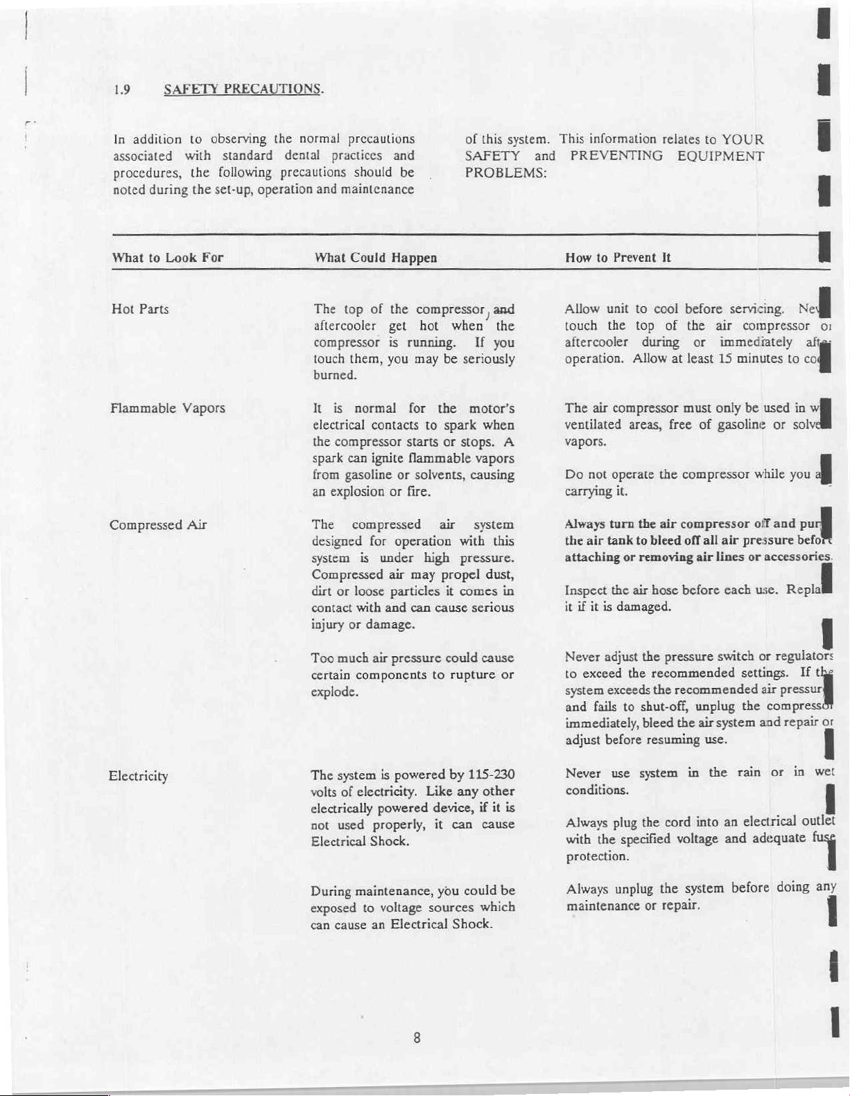
SAFETY
PRECAUTIONS.
을 mm
In
addition
associated
procedures,
noted
during
What
to
Look
Parts
Hot
Flammable
Compressed
to
observing
with
the
following
the
set-up,
For
Vapors
Air
the
standard
operation
normal
dental
precautions
precautions
practices
and
maintenance
What
Could
The
top
aftercooler
compressor
touch
them,
burned.
It is
electrical
the
compressor
spark
can
from
gasoline
an
explosion
The
compressed
designed
system
Compressed
dirt
or
contact
injury
or
should
Happen
of
the
get
is
you
normal
contacts
ignite
or fire.
for
is
under
air
loose
particles
with
and
damage.
and
be
compressor
hot
running.
may
be
for
the
to
spark
starts
or
flammable
or
solvents,
air
operation
high
may
propel
it
can
cause
of
this
SAFETY
PROBLEMS:
and
when
the
If
you
seriously
motor's
when
stops.
vapors
causing
system
with
this
pressure.
dust,
comes
in
serious
system.
and
A
This
information
PREVENTING
How
to
Prevent
Allow
touch
aftercooler
operation.
The
ventilated
unit
the top
air
compressor
vapors.
Do
not
operate
carrying
Always
the air
attaching
Inspect
it
if
it
turn
tank
the
is
it.
or
damaged.
relates
It
to
cool
of
during
Allow
areas,
free
the
the
air
to
bleed
removing
air
hose
to
YOUR
EQUIPMENT
before
the
air
or
immediately
at
least
15
must
only
of
gasoline
compressor
compressor
off
all
air
air
lines
before each
servicing.
compressor
minutes
be
pressure
or
vel]
to
used
in
or
solv
while
you
off
and
accessories.
use.
Replal
을
mě
mil
Οἱ
абы
해
개
3
1
vu]
befoi
Electricity
Too
much
air
certain
explode.
The
volts
electrically
not
Electrical
During
exposed
can
components
system
used
cause
is
of
electricity.
powered
properly,
Shock.
maintenance,
to
voltage
an
pressure
powered
could cause
to
rupture
by
Like
device,
it
can
you could
sources
Electrical
Shock.
115-230
any
other
if
it
cause
which
or
is
be
Never
adjust
the
to
exceed
system
and
immediately,
adjust
Never
conditions.
Always
with
protection.
Always
maintenance
exceeds
fails
to
before
use
plug
the
specified
unplug
the
shut-off,
bleed
resuming
system
the
or
pressure
recommended
the
recommended
cord
the
repair.
switch
unplug
the
air
system
use.
in
the
into
voltage
system
an
and
or
regulators
settings.
air
pressur,
the
compress:
and
rain
or
electrical
adequate
before
doing
If
repair
or
in
wet
outlet
any
the
What
to
Look
For
What
Could
Happen
How
to
Prevent
It
Electricity (cont.)
Improper
a
risk
event
reduces
providing
electric
grounding
of
electrical
of a short
the
an
current.
shock.
circuit,
risk of
escape
can
result
In
grounding
shock
wire
for
in
the
by
the
Ensure
properly
and
that
grounded.
repair
the
should
electrician.
system
All
be
performed
and
electrical
electrical
source
arc
maintenance
by a qualifiec
SECTION
II
2.1
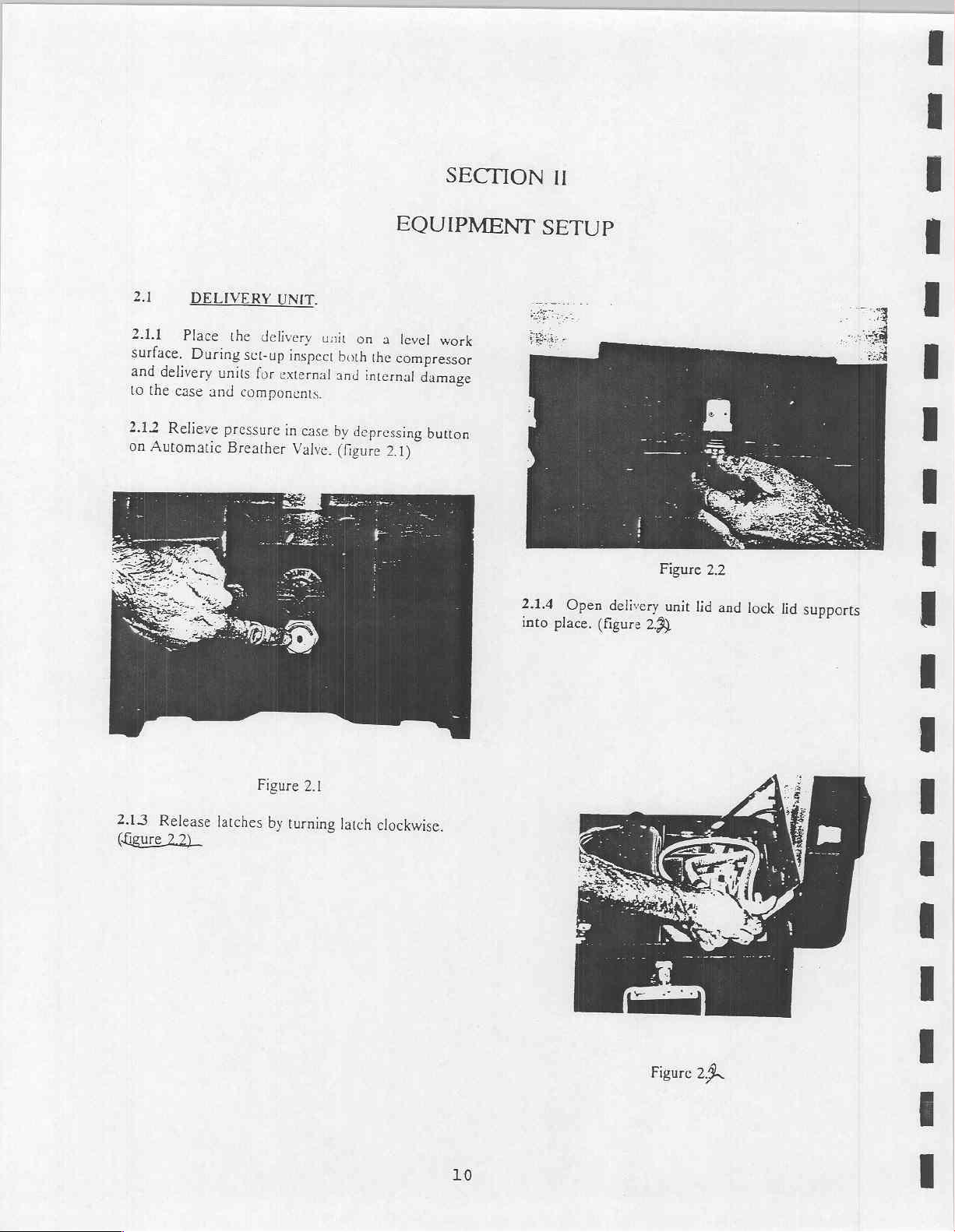
2.1.1
surface.
and
to
2.12
on
Place
delivery
the
case
Relieve
Automatic
DELIVERY
the
During
sct-up
units
and
components.
pressure
Breather
UNIT.
delivery
inspect
for
external
in
c:
ase
Valve.
unit on
both
and
internal
by
depressing
(figure
EQUIPMENT
a
level
work
the
compressor
damage
button
2.1)
SETUP
2.1.4
Open
into
place.
Figure
delivery
(figure
unit
2.3)
2.2
lid
and
lock
lid
supports
2.13
Release
(Ggure
22)
Figure
latches
by
2.1
turning
latch
clockwise.
10
Figure
24
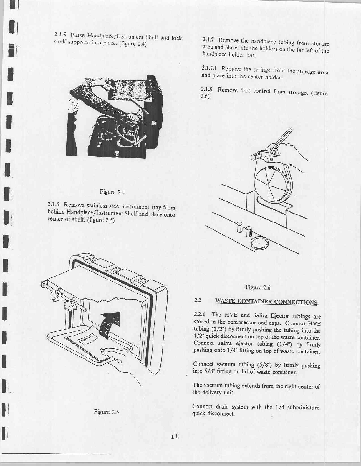
2.1.5
Raise
shell
supports
Handpivec/Instrument
into
place.
(figure
Shelf
2.4)
and
lock
2.1.7
Remove
area
and
place
handpiece
holder
the
handpiece
into
the
bar.
holders
tubing
on
the
from
far
left
storage
of
the
2.1.6
behind
center
Figure
Remoye
Handpiece/Instrument
of
stainless
shelf.
(figure
2.4
steel
2.5)
instrument
Shelf
and
place
tray
from
onto
2.1.7.1
and
place
2.1.8
2.6)
Remove
into
Remove
the
the
foot
syringe
center
control
from
holder.
from
the
storage
storage.
arca
(figure
Figure
2.5
11
22
22.1
stored
tubing
1/2"
quick
Connect
pushing
Connect
into
5/8"
The
vacuum
the
delivery
Connect
disconnect.
guick
WASTE
The
HVE
in
the
compressor
(1/2")
by
disconnect
saliva
onto
1/4"
vacuum
fitting
tubing
unit,
drain
Figure
CONTAINER
and
firmly
on
ejector
fitting
tubing
on
lid
of
extends
system
2.6
Saliva
end
pushing
top
of
tubing
on
top
(5/8")
waste
from
with
the
CONNECTIONS.
Ejector
caps.
the
the
of
container.
tubings
Connect
tubing
waste
container,
(1/4)
by
the
1/4
by
waste
container.
firmly
right
subminiature
are
HVE
into
the
firmly
pushing
center
of

222
Place
the
handpiece
the
HVE
holders
and
(on
the
Saliva
Ejector
right),
valves
(figure
2.7)
in
2.42
Place
feet
ten
to
2.43
Remove
latches
bottom
on
of
the
away
cach
the
both
case.
compressor
delivery
the
from
end
caps
side
and
(figure
on
a
by
latch
2.8)
level
surface
unit.
releasing
on
the
the
top
eight
two
and
23
23.1
center
water
relieve
water
Remove
the
the
lines.
232
to
recommended
unnecessary
control
of
24
2.4.1
cool
muffler
could
The
allow
dirt
filter
should
changed. A clean
provides
The
of
pressure
all
and
top
edge
cap,
Place
Ifthe
high
level
panel
the
entire
COMPRESSOR
Operate
and
must
reduce
air
compressor
for
that
is
be
WATER
water
the
delivery
relief
air
pressure
air
the
cap
and
with
tighten
and
the
container
water
of
mineralization
to
only
failure
components,
system.
the
well
ventilated
be
kept
air
proper
collects
located
cooling.
on
inside
changed
longer
service.
CONTAINER.
container
lines
in
delivery
when
air
Figure
either
your
of
air
pump
the
2.7
case.
toggle
then
(male
fill
to
approximately
distilled
reconnect
back
area
use
distilled
handpieces
thus
SET-UP.
compressor
area.
clear
of
and
Clean
air
compressor
the
the
piston
compressor
is
located
To
into
disconnect
quick
into
contains a moderate
(hard
prolonging
of
obstructions
the
case
or
compressor
in
open
the
the
off
disconnects)
water.
the
water
its
holder.
water),
water
or
damage
in a dry,
The
air
compressor.
are
designed
blow
filter.
and
cylinder
runs
cooler
the
lid,
position
both
1"
below
Replace
and
to
prevent
to
the
clean,
air
intake
which
off
dust
case
back
turn-
ta
the>
air
it
is
the
life
to
or
The
and
are
and
244
The
compressor
operating
other
2.45
and
end
from
Attach
quick
located
control
2.4.6
compressor
2.4.7
source,
cord
motor.
temperature.
obstructions
Remove
saliva
ejector
caps
and
the
work
air
connect
in
panetjust
Connect
If
extra
use
to
avoid
Figure
ventilation
are
necessary
on
electrical
tubings
place
area.
line
from
on
end
on
the
right
behind
the
and
delivery
distance
extra
air
voltage
2.8
openings
to
Do
not
or
near
these
cord
sets,
and
exhaust
end
caps
in
compressor
of
air
line
side
of
the
pressure
power
hose
drop
supply
modules.
is
reguired
instead
and
on
maintain
place
openings.
air
hose,
line
an
area
by
pushing
onto
male
the
delivery
gauges.
cord
to
the
of
an
power
loss
your
air
proper
objects
or
HVE
from
the
separate
female
coupler
unit
to
the
electrical
extension
to
the
12
If
you
a)
A
grounding
will
b)
In
50
c)
d)
10
increases
AWG
use
must
use
3-wire
accept
good
feet
or
gauge
and
AWG
12
and
extension
extension
plug,
and
the
plug
condition.
shorter.
(AWG)
as
8
gauge
AWG,
or
thinner.
or
number
may
cord,
cord
that
a
3-slot
on
the
larger.
also
be
sure
has
a
3-blade
receptacle
compressor.
(Wire
size
decreases.)
be
used.
10
Do
it
is:
that
not
13
SECTION
III
OPERATION
3.1
3.1.1
ejector
3.12
the
3.13
on
3.1.4
on
several
and
automatically
required
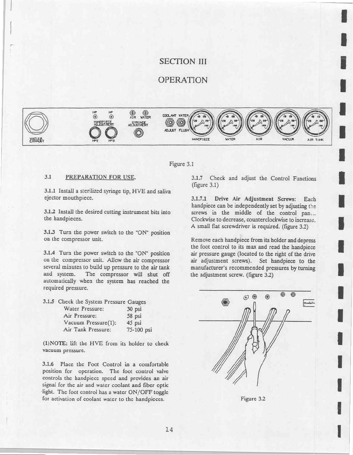
3.1.5
PREPARATION
Install a sterilized
mouthpiece.
Install
the
handpieces.
Turn
the
the
compressor
Turn
the
the
compressor
minutes
system.
pressure.
Check
the
Water
Air
Pressure:
Vacuum
Air
Tank
syringe
desired
power
power
to
The
when
System
Pressure:
Pressure(1):
cutting
switch
unit.
switch
unit.
build
up
compressor
the
Pressure
Pressure:
FOR
USE.
tip,
instrument
to
to
Allow
the
pressure
system
HVE
the
"ON"
the
"ON"
air
compressor
to
the
will
has
reached
Gauges
30
psi
58
psi
45
psi
75-100
and
saliva
bits
into
position
position
air
tank
shut
psi
Figure
off
the
3.1
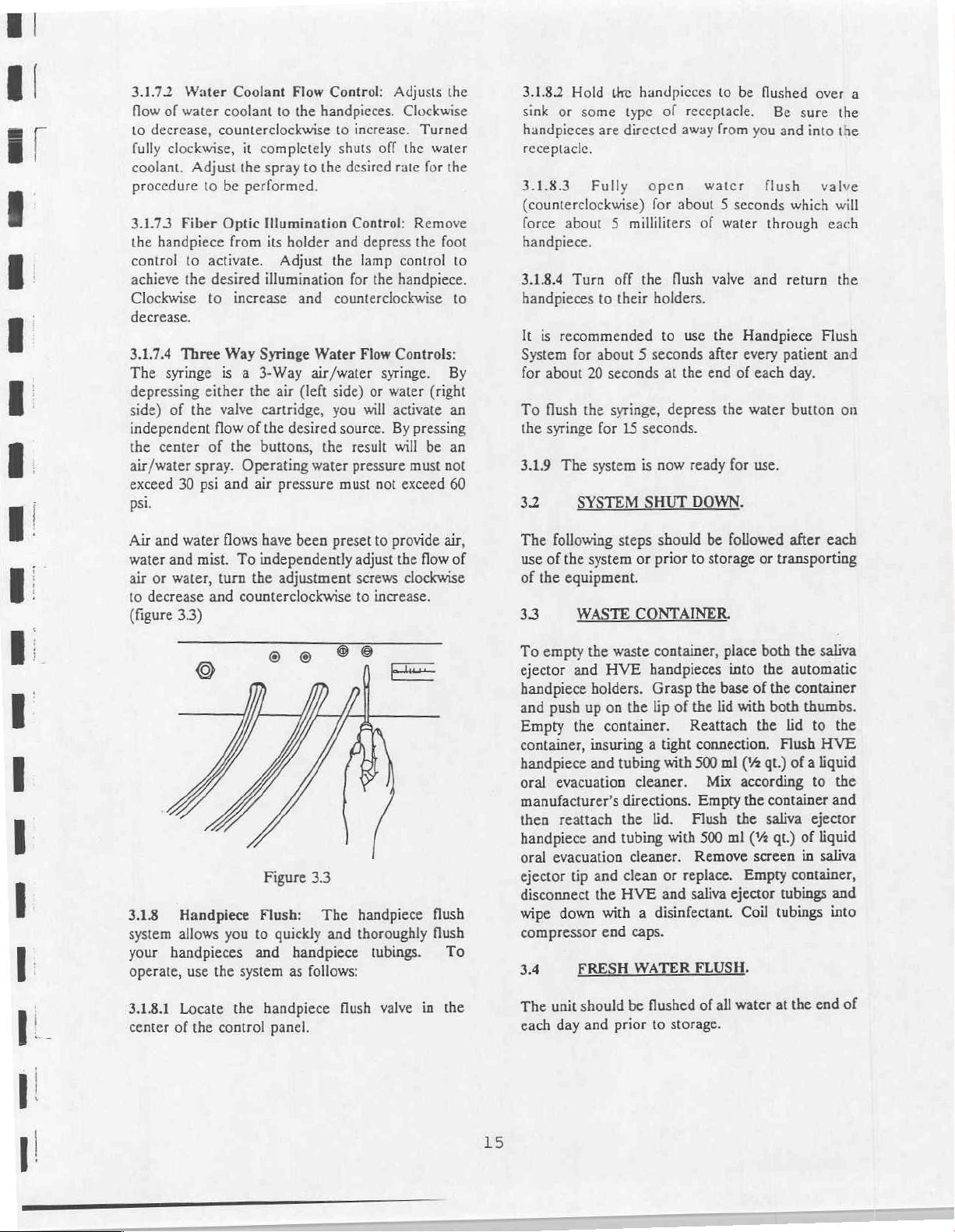
3.1.7
(figure
3.1.7.1
handpiece
screws
Clockwise
A
Remove
the
air
air
manufacturer’s
the
Check
3.1)
Drive
can
in
to
small
flat
each
foot
control
pressure
adjustment
adjustment
and
adjust
Air
Adjustment
be
independently
the
middle
decrease,
screwdriver
handpiece
gauge
counterclockwise
is
from
to
its
max
(located
screws).
recommended
screw.
(figure
voo
©
the
Control
Screws:
set
by
of
the
control
required.
its
and
to
Set
(figure
holder
read
the
the
right
handpiece
pressures
3.2)
20
Functions
Each
adjusting
to
the
pan...
increase.
3.2)
and
depress
handpiece
of
the
drive
to
the
by
turning
EE
(NOTE:
vacuum
3.16
position
pressure.
Place
controls
signal
for
«light.
The
for
activation
lift
the
the
for
operation.
the
handpiece
the
air
foot
control
of
HVE
Foot
and
water
has a water
coolant
from
its
Control
The
speed
and
coolant and
water
to
holder
to
check
in a comfortable
foot
control
provides
ON/OFF
the
handpieces.
valve
an
fiber
optic
toggle
air
14
Figure 3.2
3.1.72
flow
to
fully
coolant.
procedure
3.1.73
the
control
achieve
Clockwise
decrease.
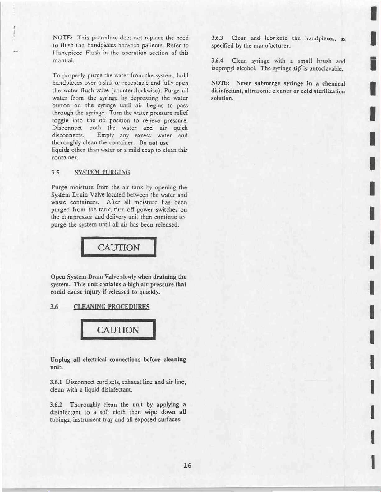
3.1.7.4
The
depressing
side)
independent
the
air/water
exceed
Water
of
water
decrease,
clockwise,
Adjust
to
Fiber
handpiece
to
activate.
the
to
Three
syringe
either
of
the
center
spray.
30
psi
of
psi.
Air and
water
air
to
(figure
water
and
mist.
or
water,
decrease
33)
Coolant
coolant
counterclockwise
it
the
be
Optic
from
desired
increase
Way
is a 3-Way
valve
flow
the
Operating
and
flows
To
turn
and
counterclockwise
Flow
to
the
completely
spray
to
performed.
Illumination
its
holder
Adjust
illumination
and
Syringe
the
air
(left
cartridge,
of
the
desired
buttons,
air
pressure
have
been
independently
the
adjustment
Control:
handpieces.
to
shuts
the
desired
and
the
counterclockwise
Water
air/water
side)
you
source.
the
water
must
preset
Adjusts
Clockwise
increase.
off
the
rate
Control:
depress
lamp
control
for
the
handpiece.
Flow
Controls:
syringe.
or
water
will
activate
By
result
will
pressure
not
exceed
to
provide
adjust
the
screws
to
clockwise
increase.
the
Turned
water
for
the
Remove
the
foot
to
to
By
(right
an
pressing
be an
must
not
60
air,
flow
of
3.1.8.2
sink
handpicces
receptacle.
3.1.8.3
(counterclockwise)
force
handpiece.
3.1.8.4
handpieces
It
System
for
To
the
3.1.9
32
The
use
of
33
Hold
tre
handpicces
or
some
type
are
directed
Fully
about 5 milliliters
Turn
to
is
recommended
for
about 5 seconds
about
20
flush the
syringe
of
the
for
The
system
SYSTEM
following
the
system
equipment.
WASTE
open
for
off
the flush
their
seconds
syringe,
15
seconds.
is
steps
or
CONTAINER.
to
of
receptacle.
away
from
water
about 5 seconds
of
water
valve
holders.
to
use
the
after
at
the
end
depress
now
should
prior
the
ready
DOWN.
be
to
storage
for
followed
be
flushed
Be
you
and
flush
which
through
and
return
Handpiece
every
patient
of
each
day.
water
button
use.
after
or
transporting
over
sure
into
valve
Flush
a
the
the
will
each
the
and
on
each
3.1.8
system
your
handpieces
operate,
3.1.8.1
center
of
©
Handpiece
allows
you
use
the
system
Locate
the
the
control
e
©
Figure
Flush:
to
quickly and
and
handpiece
as
follows:
handpiece
panel.
3.3
The
00
handpiece
thoroughly
tubings.
flush
valve
==
flush
flush
in
To
the
To
empty
the
waste
ejector
handpiece
and
Empty
container,
handpiece
oral
manufacturer's
then
handpiece
oral
ejector
disconnect
wipe
compressor
3.4
The
each
and
HVE
holders.
push
up
on
the
container.
insuring a tight
and
tubing
evacuation
reattach
and
evacuation
tip
and
the
down
with a disinfectant.
end
FRESH
unit
should
day
and
prior
directions.
the
tubing
clean
HVE
container,
handpieces
Grasp
the
lip
of
with
cleaner.
lid.
with
cleaner.
or
and
caps.
WATER
be
flushed
to
storage.
place
into
the
base
the
lid
with
Reattach
connection.
500
ml
(Y
Mix
according
Empty
the
Flush
the
500
ml
(Y
Remove
replace.
saliva
Empty
ejector
Coil
FLUSH.
of
all
water
both
the
the
automatic
of
the
container
both
thumbs.
the
lid
Flush
qt.)
of a liquid
container
saliva
qt.)
of
screen
in
container,
tubings
tubings
at
the
saliva
to
the
HVE
to
the
and
ejector
liquid
saliva
and
into
end
of
NOTE:
to
Handpiece
flush
the
This
manual.
To
properly
handpieces
the
water
water
button
through
toggle
over a sink
flush
from
on
the
into
Disconnect
disconnects.
thoroughly
liquids
container,
clean
other
procedure
handpieces
Flush
in
the
purge
the
water
or
valve
(counterclockwise).
the
syringe
the
syringe
syringe.
the
both
than
Turn
off
position
the
Empty
the
container.
water
does
not
between
operation
from
receptacle
by
depressing
until
air
the
water
to
water
any
excess
Do
or a mild
replace
patients.
the
the
Refer
section
system,
and
fully
Purge
the
begins
to
pressure
relieve
and
pressure.
air
water
not use
soap
to
clean
need
to
of
this
hold
open
all
water
pass
relief
quick
and
this
3.63
specified
3.6.4
isopropyl
NOTE:
disinfectant,
Clean
by
the
Clean
alcohol.
Never
ultrasonic
solution.
and lubricate
manufacturer.
syringe
submerge
with a small
The
syringe
syringe
cleaner
the
handpieces,
tiff
is
autoclavable.
in a chemical
or
cold
sterilization
brush
as
and
3:5
Purge
System
waste
purged
the
purge
Open
system.
could cause
3.6
SYSTEM
moisture
Drain
containers.
from
compressor
the
System
This
CLEANING
from
Valve
the
and
system
Drain
unit
injury
PURGING.
the
air
tank
located
After
tank,
delivery
until
Valve
turn
all
air
slowly
between
all
moisture
off
power
unit
has
when
contains a high
if
released
to
PROCEDURES
by
opening
the
switches
then
continue
been
released.
draining
air
pressure
quickly.
water
has
the
and
been
on
to
the
that
Unplug
unit.
3.6.1
clean
3.62
all
electrical
Disconnect
with a liquid
Thoroughly
disinfectant
tubings,
instrument
connections
cord
sets,
disinfectant.
clean
to a soft
tray
exhaust
the
cloth
and
all
before
line
unit
then
exposed
and
by
applying
wipe
surfaces.
cleaning
air
line,
down
all
a
16
SECTION
IV
Conduct
Down
41
411
manufacturer’s
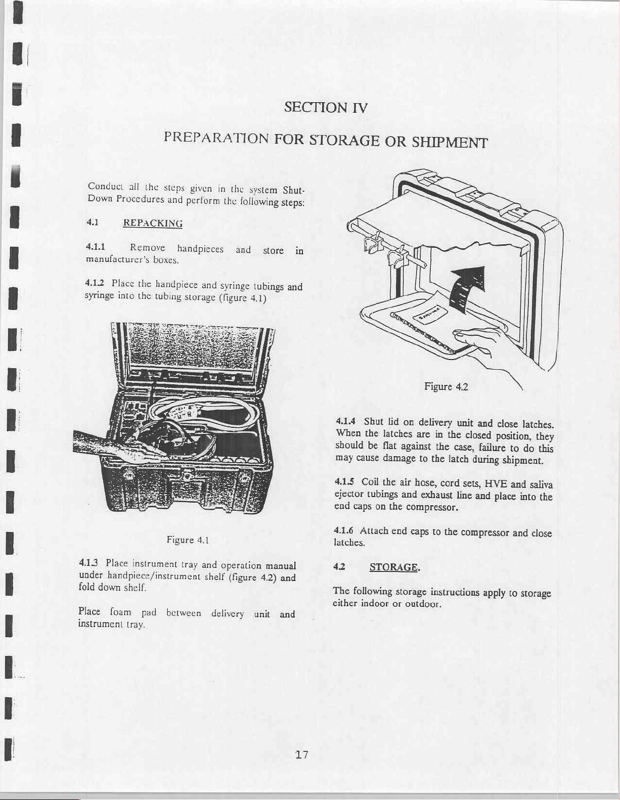
4.12
syringe
all
the
Procedures
REPACKING
Remove
Place
the
into
the
PREPARATION
steps
given
and
perform
handpieces
boxes.
handpiece
tubing
and
storage
in
the
system
the
following
and
syringe
(figure
tubings
4.1)
FOR
Shut-
steps:
store
STORAGE
in
and
4.1.4
When
should
may
cause
Shut
the
be
OR
SHIPMENT
lid
on
latches
flat
against
damage
delivery
are
in
the
the
to
the
latch
unit
closed
case,
during
and
close
position,
failure
shipment.
latches,
they
to
do
this
4.13
Place
instrument
under
handpiece/instrument
fold
down
shelf.
Place
instrument
foam
tray,
pad
Figure
between
4.1
tray
and
operation
shelf
(figure
delivery
manual
4.2)
unit
and
and
17
4.1.5
Coil
ejector
end
4.1.6
latches.
42
The
either
tubings
caps
Attach
following
indoor
the
air
and
on
the
compressor,
end
STORAGE.
storage
or
outdoor.
hose,
cord
exhaust
caps
to
the
instructions
sets,
HVE
line
and
place
compressor
apply
and
saliva
into
and
to
storage
the
close
The
ideal
(0°C)
and
be
stored
40°C)
to
Storage
cause
permanent
storage
100°F
(37°C);
in
temperatures
140°F
in
(60°C)
temperatures
damage
temperature
however
is
the
ranging
if
no
other
out
of
these
to
the
unit.
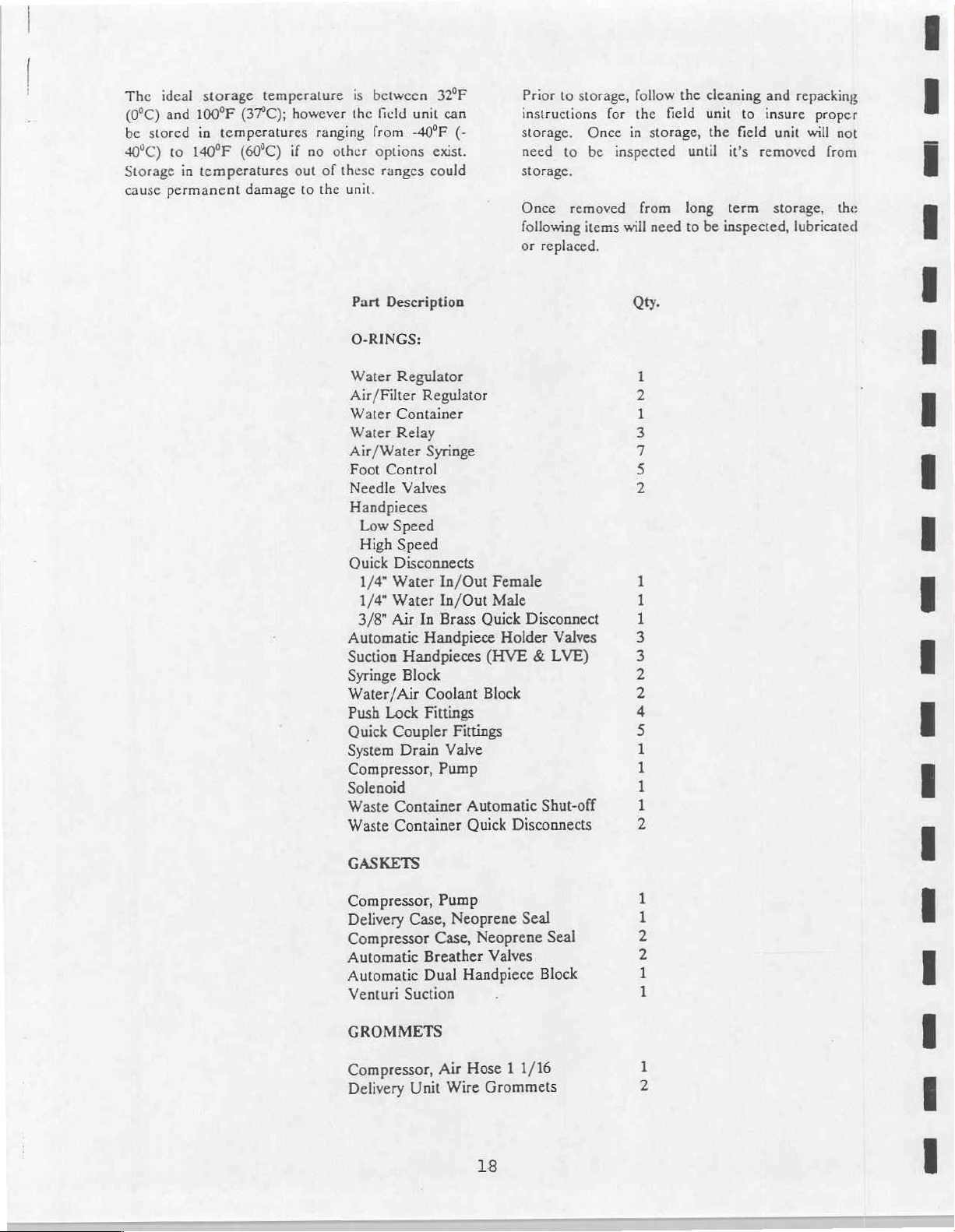
Part
O-RINGS:
Water
Air/Filter
Water
Water
Air/Water
Foot
Needle
Handpieces
Quick
Automatic
Suction
Syringe
Water/Air
Push
Quick
System
Compressor,
Solenoid
Waste
Waste
between
field
unit
from
-40°F
options
ranges
Description
Regulator
Container
Relay
Control
Valves
Low
Speed
High
Speed
Disconnects
1/4"
Water
1/4"
Water
3/8"
Air
Handpieces
Block
Lock
Coupler
Drain
Container
Container
32°F
can
(-
exist.
could
Regulator
Syringe
In/Out
In/Out
In
Brass
Quick
Handpiece
Coolant
Fittings
Block
Fittings
Valve
Pump
Automatic
Quick
Prior
to
instructions
storage.
need
to
storage.
Once
following
or
Female
Male
Holder
(HVE & LVE)
removed
replaced.
Disconnect
Valves
Shut-off
Disconnects
storage,
Once
be
items
follow
for
the
in
inspected
will
Qty.
the
field
storage,
until
from
long
need
to
m
NUS
Om
ANDO
PARA
cleaning
unit
to
the
field
it's
removed
term
be
inspected,
and
repacking
insure
unit
proper
will
storage,
lubricated
not
from
the
GASKETS
Compressor,
Delivery
Compressor
Automatic
Automatic
Venturi
GROMMETS
Compressor,
Delivery
Case,
Breather
Dual
Suction
Unit
Pump
Neoprene
Case,
Neoprene
Handpiece
Air
Hose 1 1/16
Wire
18
Seal
Seal
Valves
Block
HENNE
Grommets
SECTION
MAINTENANCE
V
5.1
5.1.1
and
optimal
The
be
+
+
+
Should
would
system
replacements,
52
52.1
gaskets
install
If
carefully
EQUIPMENT
INSPECTION.
The
equipment
disinfected
performance.
following
performed
Look
for
mechanical
safe
operation.
Insure
wear
Inspect
and
mechanical
affect
should
GENERAL
When
or
new
the old
check
there
components
frayed
servicing
diaphragms,
ones
gasket
should
after
use
visual
checks
before
the
correcting
operating
are
no
missing
electrical
or
other
safety
not
be
SERVICE
components
when
reassembling
or
diaphragm
for
pin
holes
damage
for
it
be
thoroughly
each
and
the
parts
tightness,
cords.
damage
of
use
used
the
defects
INFORMATION.
is
generally
or
cracks.
ARE
cleaned
day
to
maintain
inspections
unit:
that
or
rust,
be
or
operation,
until
are
that
the
is
to
should
could
affect
accessories
cracks,
evident
repair
made.
bave
rubber
advisable
components.
be
reused,
AND
that
the
or
to
When
servicing
component
cleaned
Any
cloth.
rinse
Periodic
consequent
trained
inspection
warranty.
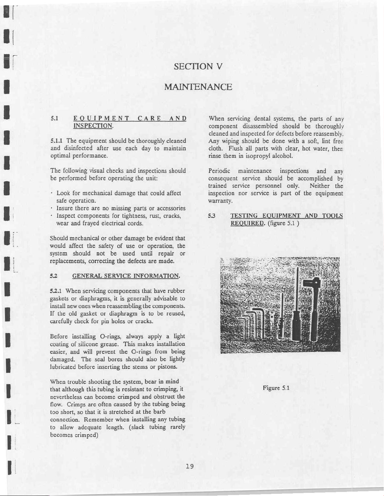
$3
and
wiping should
Flush
them
service
TESTING
REQUIRED.
dental
disassembled
inspected
all
in
isopropyl
maintenance
service
nor
for
be
done
parts
with
should
personnel
service
EQUIPMENT
(figure
alcohol.
systems,
the
should
defects
is
before
with a soft,
clear,
inspections
be
accomplished
only.
part
of
5.1)
parts
be
thoroughly
reassembly.
lint
hot
water,
and
Neither
the
equipment
TOOLS
of
any
free
ther
any
by
the
Before
coating
easier,
damaged.
lubricated
When
that
nevertheless
flow.
too
connection.
to
becomes
installing
of
silicone
and
The
before
trouble
although
Crimps
short,
so
allow
adequate
crimped)
will
can
Remember
O-rings,
grease.
prevent
seal
inserting
shooting
this
tubing
become
are
often
that
it
the
bores
the
is
crimped
caused
is
stretched
when
length.
always
This
should
the
system,
resistant
(slack
apply a light
makes
O-rings
also
stems
bear
to
and
by
the
at
the
installing
installation
from
being
be
lightly
or
pistons.
in
mind
crimping,
obstruct
tubing
barb
any
tubing
it
the
being
tubing
rarely
19
Figure
5.1
Flat
Jewelers
kit)
Used
handpieces
Flat
Screwdriver:
panels
of
frame.
Hemostats:
or
water
flow
or
repairing
Nut
Driver
from
fan
and
Ratchet
removing
Allen
5/64"
3/32"
8:
Wrenches:
Used
the
Used
holder
1/8"
Used
motor
5/32"
Used
eccentric
Screwdriver:
for
adjusting
and
three-way
Used
compressor
Useful
the
5/16":
Socket
bolts
automatic
for
through
delivery
motor
7/16"
from
(Set
for
accessing
for
adhering
to
the
for
tightening
shaft
for
tightening
shaft
(provided
air
and
syringe.
to
remove
module
tubing
For
shaft.
compressor
of
handpiece
support
and
temporarily
while
unit.
removing
or
Nutdriver
4,
provided
the
switch
the
automatic
bar
the
the
in
the
repair
water
pressure
screws from
the
delivery
stopping
troubleshooting
hex
pump
with
mechanism
holder
eccentric
Piston
the
head
7/16":
head.
repair
handpiece
to
rod
to
to
end
unit
air
bolt
For
kit)
in
the
the
drops
below
the
syringe,
serviced.
5.43
Servicing:
from
the
external
delivery
from
The
which
bottom
moisture
bowl
valve
To
main
delivery
opening
mini
bowls.
Unscrew
unscrew
5.5
unit
external
air
filter
is
housed
of
separator.
can
be
or
with
replace a clogged
power
modules
the
quick
the
the
WATER
the
numbers
the
clement
Remove
case.
(cut
out
case.
consists
in a bowl,
the
regulator.
Any
released
automatic
switches
and
system
coupler
bowl from
filter
element
FILTER
indicated
is
the
Pull
for
hand)
of a replaceable
liquid
by
opening
drain
air
filter
on
beth
relieve
drain
valve.
located
the
and
while
clogged
delivery
up on
until
and
attached
It
also
accumulations
the
system.
element,
the
compressor
all
air
Disconnect
below
the
regulator
replace.
operating
and
must
unit
frame
center
unit
is
filter
element
to
serves
in
system
turn
off
pressure
regulator
and
be
of
(rez
the
as
a
the
drain
the
ane-
by
the
then
Syringe
removal
the
main
servicing
Air
Pressure
gauge
with a 0-100
pressure
unit.
5.4
5.4.1
Regulator
pass
through
Filter
elements
become
the
regulators.
5.42
Checking
air
supply,
that
the
external
While
pressing
pressure
air
is
15
Tools:
of
air
the
at
MAINTENANCE.
sufficiently
water
water
gauges.
psi;
(Provided)
threaded
and
water
syringe.
Test
psi
various
Filters:
filters
should
the
Be
sure
supply
source.
the
The
for
water
points
syringe
barrel
Gauge:
range,
before
clogged
Filters:
there
maximum
it
This
assembly.
supply
Use
for
while
The
air
entering
be
serviced
to
Connect
is
water
tube
button,
is
10
tool
is
used
Be
sure
is
turned
use
troubleshooting
and
impede
is
psi.
off
an
air
pressure
in
checking
water
supplies
the
regulators.
when
the
the
unit
in
the
tank,
connected
check
the
pressure
If
the
drop
pressure
prior
flow
to
to
system
for
that
to
air
the
they
to
its
or
an
for
The
water
is
filtered
with a reusable
5.51
Servicing:
tubes
from
the
water
filter.
Relieve
button
on
housing,
the
disc
dry
it
with
HVE.
when
assembling
5.6
Air
is
drawn
keep
dust
system.
filter
removed
components
all
the
water
separate
with
isopropyl
the
Be
sure
IR
INTAKE
into
and
Do
not
to
in
by an
porous
disc
Disconnect
container
air
pressure
container.
and
remove
alcohol and
air
from
the
O-ring
the
filter
FILTER.
the
compressor
other
debris
operate
prevent
the
compressor
in-line
filter
the
before
by
depressing
Unscrew
the
the
syringe
is
properly
housing.
from
the
compressor
undue
wear
pump.
35
micron
element.
air/water
servicing
the
filter
disc.
then
thoroughly
or
with
positioned
and
filtered
entering
with
on
the
filter
supply
the
the
red
filter
Clean
the
to
the
air
the
teflon
20
2)
3)
External
Internal
Leakage
Leakage
Make
sure
down
for
15
5.6.1
Servicing:
all
times. A dirty
compressor
filter
becomes
To
replace
the
filter
is
dirty,
it
with a mild
5.7
The
instruments
through
delivery
the
in
simply
AIR/WATER
operating
air
unit
pressure.
5.7.1
Checking
should
5.72
regulators,
between
air
Be
Check
before
be
as
Water
Pressure:
Air
Pressure:
Vacuum
Servicing:
verify
70-100
regulator
sure
there
the
filters
adjusting
the
compressor
minutes.
Keep
air
intake
to
operate
dirty,
it
must
filter,
pull
place
and
replace
pull
it
out
detergent
REGULATORS.
air
and
and
vacuum
regulators.
indicate
follows:
Pressure:
the
the
Regulators:
Before
that
psi.
Do
if
supply
pressure
is
water
as
explained
the
regulators.
has
the
air
intake
filter
at
full
capacity.
be
cleaned
out
the
with a new
and
clean;
and
warm
water
devices
The
gauges
regulated
30
psi
(- 5 psi)
58
psi
(+/- 5 psi)
45
psi
(+/- 5 psi)
adjusting
the
air
not
attempt
is
in
the
in
the
at
least
filter
clean
will
not
allow
When
or
replaced.
tow
pins
one.
you
may
water.
pressures
are
controlled
inside
air
and
The
pressures
the
air
or
tank
pressure
to
adjust
less
than
water
container.
Filters
cooled
at
the
the
holding
If
it
wash
to
the
the
water
water
is
the
70
psi.
section
5.73.1
is
5.73.2.
leakage
following
1)
the
valve
leaking
2)
from
regulator
tightening
new
3)
from a loose
assembly.
leak,
5.733
indicates
unit
inlet
replacing
the
material
5.7.4
leakage
by
ting.
water
Install a new
Filter
covered
Leakage
Leakage
in
External
from
action
filter
bowl
core.
persists,
the
bowl
or
the
O-ring.
around
Leakage
If
replace
Internal
that
is
not
being
seal.
or
new
poppet,
on
Servicing
around
replacing
Leakage
pressure
the
from
Try
from a defective
around
tightening
the
the
This
cleaning
the
the
regulator.
Element:
Filter
Leakage:
the
air
according
the
purge
results
tightening
replace
the
not
being
bowl.
If
the
the
cover
or a defective
diaphragm.
Leakage:
pressure
used,
there
can
the
be
certain
sealing
the
Water
the
inlet
sleeve
around
the
are
indications
Service
section.
from a loose
the
top
top
the
normally
surfaces
or
of
the
filter
In
the
event
of
filter-regulator,
to
the
point
of
valve
at
the
bottom
or
the
valve
core.
valve core.
of
the
filter
bowl
screwed
leaking
cover
If
creeps
poppet.
that
or
replacing
adjusting
tightly
O-ring
persists,
of
the
regulator
does
the
air
pressure
upward
is
air
leaking
be
When
there
in
the
Regulator:
outlet
can
the
knob
of
internal
seal.
diaphragm
not stop
when
corrected
is
no
valve
be
corrected
internal
or
clement
external
take
the
leakage:
of
defective
If
the
results
onto
the
Try
install
a
results
the
gauge
the
past
the
by
installing
foreign
body.
External
o-
erratic
leakage.
If
adjustment
required,
increase
pressure.
necessary
before
water
5.73
Regulators
problems:
1)
pressure
reading
syringe
Servicing
Clogged
of
turn
When
to
relieve
button.
used
either
the
air
or
the
regulator
or
counter-clockwise
decreasing
the
gauge.
the
Air
are
Filter
the
the
pressure
Do
this
Regulator:
subject
Element
water
knob
water
in
by
The
to
three
pressure
clockwise
to
decrease
pressure,
the
pressing
system
Air
types
it
the
Filter-
is
to
is
of
21
58
The
easily
the
5.8.1.1
approximately
straight
not
is
only).
HREE
way
three
serviced
repair
kit.
Changing
out.
visible.
syringe
with
three
Push
Retighten
WAY
the
the
turns.
sterile
SYRINGE.
designed
is
and
tools
Loosen
Tip:
Pull
in
tip
retaining
can
it
that
so
contained
parts
retaining
contaminated
reminder
until
(hand-tight
nut
be
in
nut
tip
ring
5.9
The
piston
be
drops
operation
simultaneously
5.9.1
unplug
the
AIR
air
compressor
and
teflon
replaced
below
of
Servicing:
the
delivery
COMPRESSOR
whenever
the
the
or
unit
unit
pump
coated
and
to
sleeve.
the
level
handpieces
after
500
Before
servicing
disconnect
relieve
PUMP.
contains a teflon
These
parts
air
compressor
required
and
hours
of
the air
any
pressure.
efficiency
to
vacuum
operation.
the
compressor,
hose
ring
should
maintain
system
from
apply a small
the
o-ring
into
into
place
for
to
the
O-ring.
worn.
plate,
entire
the
screws
Place
tighten
Ensure
gasket
head
7/16"
and
the fan
the
assembly
socket
tighten.
hex
amount
proper
proper
and head,
onto
of
place.
seating and
Inspect
alignment
onto
and
the
motor
head
screw.
Be sure
o-ring
lubrication
to
to
the
gasket
of
then
carelully
the
pump
ratchet,
shaft
guide
the
prevent
and
the
o-ring
lower
frame.
replace
and
replace
to
hold
O-ring
damage
replace
valve
the
Using
the
four
and
if
5.9.1.1
the
remove
(air
a
and
Using
screw
motor
Using
on
rod
assembly.
Using a ratchet
driver,
top
head
access
the
assembly.
through
Removing
compressor
the
hose)
flat
screwdriver
carefully
the
from
shaft
the
the
piston
forward
remove
of
the
assembly
to
the
O-ring
the
end
of
the
remove
5/16"
the
and
5/32"
rod
from
pump
and
piston
from
Pull
pump
the
Piston
pump,
plate
compressor
and
Nut
inside
pull
allen
assembly
and
the
head assembly.
the
the
frame
it
oppesite
remove
the
end
Driver,
of
the
the fan
wrench,
the
bearing
deep
7/16"
four
machine
valve
plate
and
cylinder
bottom
cylinder
and
will
from
and
Assembly:
be
necessary
of
the
exhaust
module
plate.
remove
sleeve
housing.
the
retaining
the
fan
mounted
the
shaft.
loosen
the
pull
the
on
the
socket
or
screws
Carefully
assembly
sleeve.
of
the
and
discard.
To
access
to
side
Use
screws
Hex
head
on
the
set
screw
connecting
eccentric
7/16"
nut
from
the
lift
the
up
to
gain
Remove
valve
plate
piston
up
Rotate
piston
assembly
with
screws.
the
assembly
use.
fan
will
be
Replace
by
hand
slides
fit
snugly
the
and
check
to
see
smoothly. A new
at
first
but
will
end
plate
and
retaining
if
the
pistoa
loosea
59.12
replacement
of
piston’s
cylinder
Place
of
align
the
Push
the
set
Place
Replacing
the
cylinder
teflon
sleeve.
the
piston
the
pump
the
slash
back
of
the
piston
eccentric
screw,
the
O-ring
the
parts,
drop
sleeve.
ring
and
frame
and
mark
on
the
pump
connecting
assembly,
onto
Piston
Assembly:
the
piston
Be
careful
or
the
teflon
cylinder
drop
the
top
frame.
rod
align
the
valve
sleeve
into
and
through
not
to
coating
through
place.
of
cylinder
onto
the
firmly
plate
Using
new
the
damage
on
the
Carefully
sleeve
bearing
tighten
assembly
top
the
the
top
to
on
the
and
22

DAILY
Daily
Function
Air
Tank
Vacuum
Delivery
Water
System
High
Speed
Low
Speed
Scaler
Fiber
Optic
FUNCTIONAL
Checklist
Pressure:
System
System
Pressure:
Pressure:
Pressure:
Handpiece:
Handpiece:
System:
CHECKLIST
AND
75-100
45
psi
58
psi
30
psi
Set
to
Set
to
Set
to
Handpieces
MAINTENANCE
psi
manufacturer’s
manufacturers
manufacturer’s
Illuminate
specifications
specifications
specifications
when
SCHEDULE
(optional)
(optional)
(optional)
operated
(optional)
Maintenance
Purge
Moisture
Thoroughly
Flush
Handpieces
Check
Compressor
Check
Compressor
and
O-ring
Check
Air
Regulator
Check
Water
Examine
of
Examine
all
sealing
electrical
system
Examine
relief
Cases
valve
Schedule
from
Air
Clean
and
(15
seconds)
Air
Efficiency
Filters
Filter
tubings,
gaskets
wiring,
for
damage,
(optional)
Storage
Disinfect
Intake
Tank
Unit/Vacuum
Filter
for
Replacement
and
o-rings
transformers,
cracking
for
Cleaning
for
switches
and
operation
System
of
any
or
Replacement
Teflon
wear
and
and
lighting
of
pressure
Components
loss
Frequency
Twice
Daily
Daily
Between
Every
250
frequently
Every
250
Every
1000
Every
500
Annually.
operation
Annually
Annually
(more
Patients
hours
of
operation
under
dusty
hours
of
hours
of
hours
of
or
2,000
often
if
humid)
or
conditions
operation
operation
operation
hours
more
of
23

SECTION
VI
TROUBLESHOOTING
6.1
The
however,
or
If
wrong,
extensive
If
sections
Problem
Compressor
Air
BASIC
following
designed
training.
the
Field
the
repair.
the
information
covering
Leaks
Compressor
delivering
enough
TROUBLESHOOTING
information
to
help
Unit
is
maintained
information
does
the
individual
Module:
is
not
air
is
not
intended
you quickly
and
contained
not
identify
components.
Possible
Hose
Piston
Restricted
GUIDE.
identify
given
proper
herein
tells
and correct
fitting
and
to
isolate
the
you
Cause
loose.
sleeve
air
intake
every
problems
care,
it
will
what
can
the
problem,
may
be
filter.
problem
that
can
provide
be
done
more
worn.
that
could
be
repaired
reliable
prior
to
detailed
arise
with
the
without
service.
physically
information
Correction
Tighten
Replace
Maintenance),
Clean
any
special
If
something
removing
is
fitting.
piston
or
replace
Maintenance).
Field
Unit.
equipment
does
the
available
and
the
air
intake
It
is,
go
unit
for
in
the
sleeve
filter (refer|
(refer
Restricted
Compressor
Motor
will
Air
Intake
will
not
not run
start
Hole
in
hose.
Air
Leaks.
Dirty
air
On/Off
plugged
Motor
has
Fuse
tripped.
switch
in
overload
tripped.
blown,
filter.
is
off.
securely.
protection
circuit
24
Cord
breaker
is
not
switch
Replace
Tighten
the
hose
fittings.
necessary.
Clean
or
replace
Maintenance).
Secure
Let
automatically
as
a
that
Cord.
motor
1.
Check
necessary.
fuse
or
circuit
specified
cool
fuse
assembly.
Reapply
with
off
and
re-start.
box
for
Reset
circuit
breaker
for
your
particular
new
the
blown
breaker.
with
teflon
filter
tape
(refer
compressor
fuse
and
cod
Do
not
higher
rating
branch
o]
i
I
tc
』
us

Problem
Possible
Fuse
blown,
tripped
Loose
(cont.)
electrical
Cause
circuit
breaker
connections.
Correction
2:
Check
for
Delay
Time
a
3.
Check
4.
Check
5.
Disconnect
circuit
branch
Disconnect
connections
for
the
or
operate
circuit.
proper
extension
fuse.
low
voltage
other
fuse.
electrical
the
power
inside
supply.
case.
You
should
problem.
cord.
Replace
appliances
compressor
Check
if
on
be
its
using
faulty.
from
own
wiring
Delivery
Audible
inside
the
Water
in
Air
water
flow
leakage
control
bubbles
and syringe
Reduced
or
water
Module:
air
leak
control
from
panel
in
the
or
no
flow
from
panel
with-
coolant
water
of
air
Possible
Faulty
motor.
Loose
fitting
Loose
fitting.
Low
water
Loose
fitting.
Blocked
defective
or
tubing.
level
in
or
pinched
capacitor(s).
container.
tubing.
Check
capacitor.
Have a motor
Remove
apply a soapy
leak
components.
Apply
for
Refill
Check
if
Make
not
unit
is
found,
water
pressure,
leak.
Tighten
container.
all
water
necessary.
sure
tubing
pinched,
inspect
shop
check,
from
case.
solution
tighten
or
replace
fastener
is
not
for
replace
To
to
connections.
or
complete a visual
leaking
connections
pinched.
if
help
find
replace
component.
and
If
faulty.
leakage,
When
leaking
tighten
tubes
blockage.
check
are
Two
run
when
Main
shows
no
air
or
air
100
to
more
only
gauge
psi
unit
handpieces
one
should
indicator
but
there
is
O-ring
switch
air
Air
in
handpiece
may
be
through.
filter/regulator
holder
defective,
is
not
allowing
open.
25
valve
Replace
Insure
regulator
O-ring.
is
open
and
set
to
58
psi.

Problem
Possible
Cause
Correction
Water
but
the
Control
to
3-way
there
is
scaler
Unit:
Water
handpiece
on,
but
handpiece
in
use
Handpieces:
Low
pressure
handpieces
Neither
work
of
(no
air
syringe
not
water
or
high
leaks
when
switch
the
handpieces
or
water)
to
speed
from
is
not
to
is
Needle
valve
line.
Defective
Air
are
Pinched
O-ring
adjustment
closed
or
tubing.
Air
compressor
or
air
supply
connected.
off
or
screws
or
adjusted
crimped
not
tubing
pinched
in
water
relay.
on
tri-block
to
low.
foot
control
functioning
not
water
Insure
water
switch
position.
Remove
Inspect
Check
psi
adjustment
counterclockwise
Check
Check
tubing
cartridge
O-ring.
tank
air
prior
to
adjusting
tubing
operation
connection.
Clean
pressure
screws
to
and
on
valve
stem
and
gauge.
handpiece
(recessed
increase
remedy
of
compressor
console
from
replace
Insure
block.
in
pressure.
or
replace
is
in
water
if
necessa
100 + 5
consol
wind
system
"O
rela:
<
"ji
No
water
either
there
is
syringe
Three
Way
Valve
Cartridge
water
Valve
Cartridge
sticks.
coolant
handpiece,
water
from
from
Syringe:
leaks
button
but
the
No
or
low
container.
Water
supply
position.
Water
switch
turned
Worn
a)
b)
с)
off.
O-rings.
Debris
Worn
valve
O-rings.
level
toggle
on
build
spring.
foot
up.
of
water
is
in
control
the
in
off
Check
and
Switch
Replace
Clean
toggle.
O-rings
module
assembly.
Replace
Replace
spring.
O-rings.
refill.
or
cavity
valve
and
assembly.
valve
card]
I
I
I
26

了
Problem
Nozzle
connection
water/air
nut/tube
leaks
Possible
a)
Loose
Cause
connection.
Correction
Check
Tighten
Connections.
nozzle
nut.
Clogged
Spray
depressing
immediately
water
Evacuation
Low
nozzle
mist
valve
Suction
tube
occurs
depression
System:
when
air
valve
following
b)
Worn
O-rings.
Debris
from
or
sterilization
Worn
nozzle
Hose
container.
Lid
Kinked
Hole
Barb
Clogged
connections
loose
suction
in
vacuum
connections
tubing
delivery
assembly
system
deposits.
tubings.
tubing.
on
tubing
on
barbs.
tubing
O-rings.
loose
on
loose.
Replace
Run
ultrasonically
Replace
Check
Snap
Check
Inspect
Tighten
Check
a
with
O-rings.
cleaning
O-rings.
connections.
into
place.
for
possible
each
tube
barbs
for
possible
wire with a dull
wire
through
clean.
for
into
clogging.
kink.
leaks.
lid
by
edge.
nozzle
turning
Clean
tube
and/or
clockwise.
tubings
with
No
Vacuum
Screen
clogged.
Air/Filter
Regulator
Vacuum
moisture.
One
connected
Lid
Air
Regulator
Air
in
regulator
is
generator
of
the
vacuum
to
is
not
on
compressor
is
supply
line
saliva
ejector
filter
set
to
low.
is
filled
hoses
container.
container.
is
not
on.
turned
is
blown
off.
27
is
dirty.
with
is
not
off.
tip
Clean
or
Replace
Adjust
Take
Check
Snap
Check
Adjust
filter.
to
generator
connections.
onto
compressor.
regulator
Reattach.
replace
38
screen.
psi.
apart
container.
to
38
and
psi.
dry.

Problem
Fiber
Optic:
No
Light
Possible
Bulb
loose.
Cause
Correction
Secure
bulb
into
socket.
Bulb
burnt
Power
supply
Faulty
air
control.
Loose
wiring.
out.
cord
signal
loose.
to
lamp
Replace
Push
Check
control
Check
transformer,
wire
manufacturer's
bulb.
firmly
air
signal
box.
wires
is
found,
into
connected
and
refer
repair
receptacle.
tubing
handpiece
connection
into
lamp
tubing.
to
wiring
diagrams.
on
lam;
control
If a loose
schematic
A
a
28

20p9adsu]
3300
4opodsuj
nea
AŒYODAA
TV.LNAG
NOILOHASNI
-
LINO
HOVAOLS
JHIH
WO00TZ
ANV
AONVNALNIVN
TAGOW
20padsu]
aeg
10322451
ea
40p2dsu]
ned
*
SAaulA0JSUeAl
493114
9XPAUT
ALY
sossaudwog
anpao04d
5191114
Kau9131443
Jozejnboy
499114
40ssouduwo3
4978M
Jly
sbuLy-0
51935969
‘sbuLqgni
шэ3$Ас
Би!зЗчЧБЕЛ
“BULALM
‘$9423
1291499913
1м5
|
|
"238
‘Buryoesg
‘abeweg
:sase)

|
|
4opadsuj
|
α
-
yea
TUOITA
TVINAC
NOLLIAASNI
-
LINA
HDVAOLS
TTAIA
W00TZ
ANV
J0padsuy
ned
αογοοάσαι
eq
αοροάσαι
eq
-
NE
-
-
-
때
=
때
ADNVNALNIVIA
TAGOW
dojaadsuj
ard
aunpao04d
mmm
mm
mm
mm
mm
mm
mm
=.
Procedure
Date
Inspector
MAINTENANCE
MODEL
Date
Inspector
Date
Inspector
Date
Inspector
2100M
AND
STORAGE
FIELD
UNIT
INSPECTION
-
DENTAL
RECORD
Date
Inspector

32

ILLUSTRATIONS
33


1
Ref.
No.
Description
AUTOMATIC
HANDPIECE
HOLDER
Part
No.
30-0003
Qty.
1
一
らい
ょ
の
いら
コ
So
どら
ら
a
Ve
κ
Normally
Holder
Pivot
Set
Adaptor
Set
Pin
Pilot
Screw,
Valve
Spring*
O-Ring*
Stem*
Automatic
Link*
Screw,
Screw,
.061 x 1/2"
Valve
4 x
Body*
Opened
6-32 x 3/16"*
6-32 x 1/2"
Assembly
1/2"
Handpiece
(Air
Polyfast*
Activated)
Holder
Hardware
Kit
90-6550
90-8057
90-8050
m
IMAN
“
Normally
Holder
Pivot
Set
Adaptor
Set
Pin,
Switch,
Screw, 4 x
Automatic
Link*
Screw,
Screw,
.061 x 1/2"*
Electric
Closed
6-32 x 3/16"*
6-32 x 1/2"*
1/2"
Handpiece
(Electric
Activation
Polyfast*
Activated)
Holder
Hardware
Kit
90-6550
20-6009
90-8051
mi
ma
mi
ta mi
Ven
35


Ref.
No.
Description
UNIVERSAL
HOLDER
Part
No.
30-0005
Qty.
em
πα
1
2
3
4
Screw,
Adaptor
Holder
Set
4
Screw,
x
1/2"
6-32
Polyfast
x
1/2"
13-2089
2
1
1
2
Ee
ee
ee
U
eS
—
37

me
AN
O
ON
AZ RR
E
GA)
6
©
=
A
A
AŞ
O
OR
A
DC
A
a,

Ref.
No.
Description
SALIVA
EJECTOR
TIP
Part
No.
30-0050
Qty.
1
2
3
4
5
6
7
È
as
Saliva
Screen*
Valve
Spool
Quick
O-Ring*
Lever*
Screen,
Repair
Ejector
Body
Disconnect
Saliva
Kit
Tip
**
Ejector
(includes
Kit
(Pkg.
5
O-Rings)
100)
30-0051
13-0056
90-9220
90-8080
1
1
2
l
39

Les

Ref.
No.
Description
CENTRAL
VACUUM
LEVER
VALVE
Part
No.
30-0060
Qty.
EN
Ss
μα
μαι
M
μα
ma
1
2
3
4
5
6
7
O-Ring,
Universal
Valve
Spool
Quick
O-Ring,
Lever
Body
Disconnect
Tip
Adaptor
Tip
Quick
Adaptor
Disconnect
13-0350
13-0355
90-6525
3
1
1
1
1
1
1
41


Ref.
No.
Description
VACUUM
CANISTER
ASSEMBLY
Part
No.
Qty.
1
2
3
4
5
6
7
8
9
10
11
12
13
14
15
16
17
18
*
Tube,
Barb,
Barb
Lid,
Plate,
Nut,
Elbow,
Float
Ball,
Ball,
Screw,
Vacuum
O-Ring
Elbow,
Tube,
Tubing,
H.V.E.
Saliva
Vacuum
5/8"
ID
5/8" x 1/2"
1/4",
Elbow
Vacuum
Aluminum
1/4"
1/2"
Tube
3/4"
20
Stainless
1/2"
1/2"
3/8"
Valve
Ejector
Canister*
MPT
MPT x 1/2"
Aluminum
mm
Plastic
Canister*
Barb x 1/2"
Corragated
Saliva
with
Valve
Canister
Corragated
MPT
Nylon
1/4"
MPT
Nylon
MPT
Steel
8-32 x 3/4",
MPT,
Asepsis
Ejector
Lever,
Assembly
Autoclavable
with
Lever,
Nylon
Nylon
Allen
Nylon
Autoclavable
Kit
31-0312
33-2186
33-2078
90-6225
05-1300
13-1210
33-2084
07-0592
15-5210
15-5215
13-1926
30-3210
13-0370
33-2085
31-0305
31-0200
30-0060
30-3210
30-3210
1
1
|
i
1
1
1
1
1
1
2
it
1
1
6
ft.
6 ft.
1
1
43
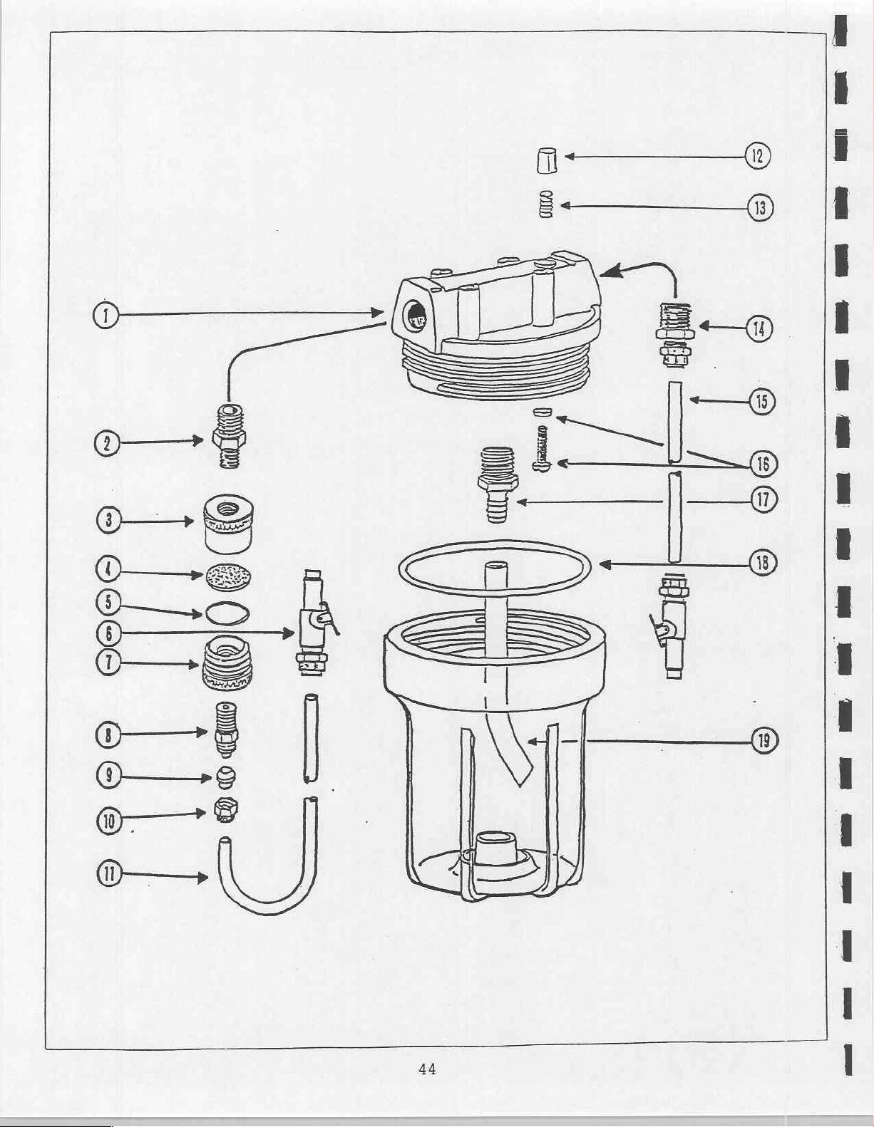

Ref.
No.
Description
WATER
CONTAINER
ASSEMBLY
Part
No.
Qty.
1
2
3
4
5
6
fii
8
9
10
11
12
13
14
15
16
17
18
19
*
re
Res
Cap,
Water
Adapter,
Filter,
Filter
Filter,
Male
Filter,
Poly
Poly
Nut,
Tube,
Pressure
Spring**
Connector,
Tube,
Screw
Barb,
O-Ring,
Tube,
Filter
Water
Nut
and
1/4"
Female
Disc*
O-Ring*
insert
Male
Flow
Sleeve,
1/4"
**
1/4"
Release
1/4"
and
3/8" x 1/2"
Water
3/8"
Assembly
Container
Poly
Container**
MPT x 1/8"
Body*
1/4"
With
Body*
Connector,
1/4"***
Blue
Button**
Poly
1/4" x 1/4"
Red
1/8"
Washer**
MPT
Container**
Gray
Sleeve
1/4"
MPt
Shut Off
1/8"
MPT x 1/4"
MPT
Poly
33-2125
30-2061
30-1020
33-1106
31-0100
33-1110
31-0101
33-2155
13-0399
31-0210
30-2060
30-3000
33-0150
1
1
1
1
1
1
1
1
1
1
1
1
1
1
1
1
1
1
1
45

46

WATER
REGULATOR
30-2040
Ref.
No.
AWN=
YOU
D00
Description
Lock
O-Ring
Body
Piston
Regulating
Spring
Bonnet
Panel
Adjusting
Nut
and
Valve
Rest
Mount
Screw
Assembly
Spring
Nut
Part
No.
13-0395
Qty.
ジー
ein
κα
μαμα
5
に
47

=
2919
|
|
e
©
©
©
48
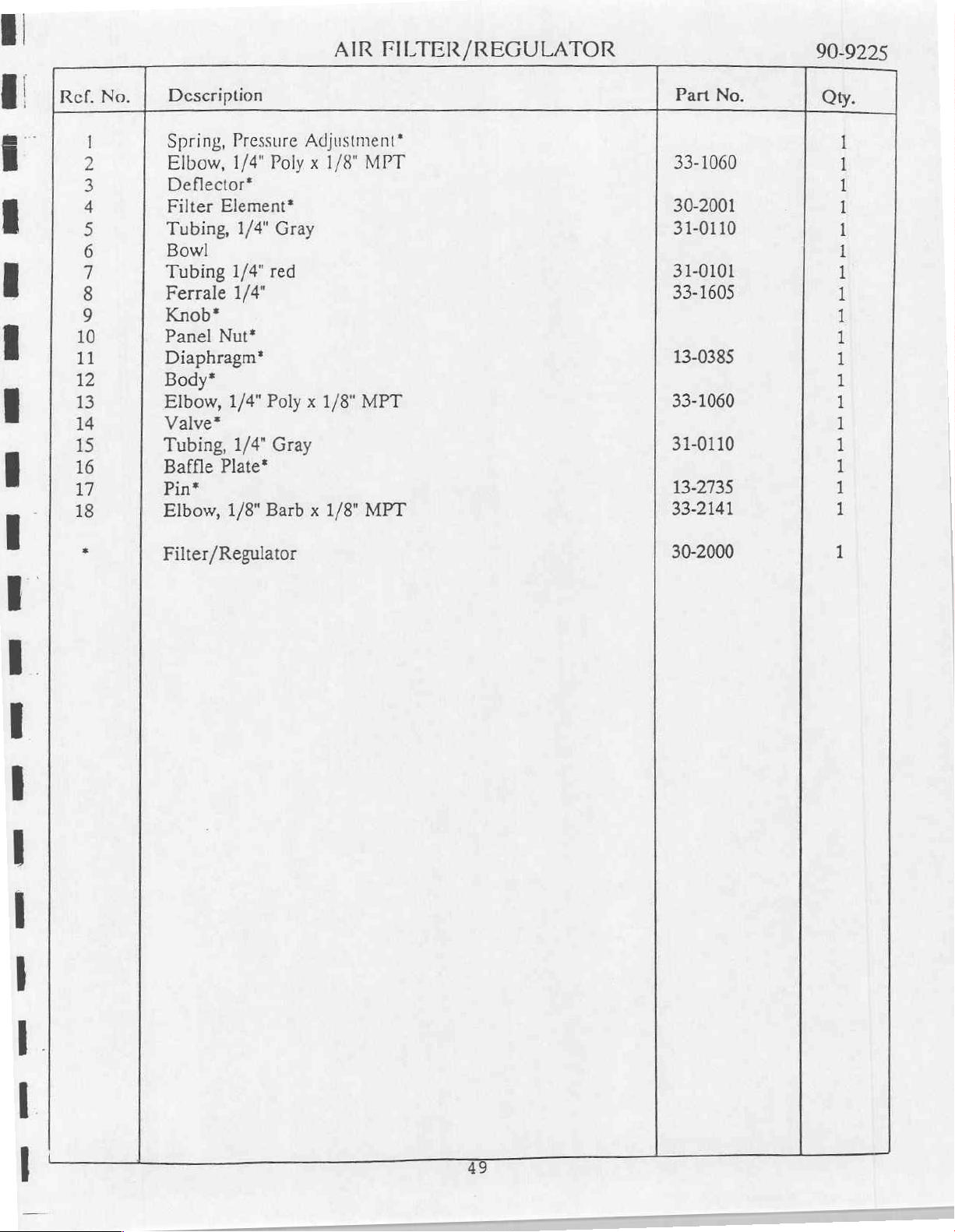
Ref.
No.
Description
AIR
FILTER/REGULATOR
Part
No.
90-9225
Qty.
1
2
3
4
5
6
7
8
9
10
if
12
13
14
15
16
17
18
*
Spring,
Elbow,
Deflector*
Filter
Tubing,
Bowl
Tubing
Ferrale
Knob”
Panel
Diaphragm*
Body*
Elbow,
Valve*
Tubing,
Baffle
Pin*
Elbow,
Filter/Regulator
Pressure
1/4"
Poly x 1/8"
Element*
1/4"
Gray
1/4"
red
1/4"
Ναι”
1/4"
Poly x 1/8"
1/4"
Gray
Plate"
1/8"
Barb x 1/8"
Adjustment*
MPT
MPT
MPT
33-1060
30-2001
31-0110
31-0101
33-1605
13-0385
33-1060
31-0110
13-2735
33-2141
30-2000
1
1
1
1
1
1
1
i
ᾳ
1
1
1
1
1
3
1
1
il
1
49


Ref.
No.
Description
FOOT
CONTROL
(wet/dry
valve)
Part
No.
30-0180
Qty.
10
11
12
13
14
15
16
17
18
19
20
21
22
23
24
25
26
27
28
29
30
31
32
33
34
35
36
37
38
1
2
3
4
5
6
7
8
9
Cover
Cover
Spring"
Plunger*
O-Ring*
Spring*
Valve
O-Ring*
Poppet
Spring*
Base
Screw,
Hole
Interconnect
Barb
Barb
Plastic
Barb
Barb
Water
Cap
Screw,
Plunger
Lock
Spring**
Guide
Keeper
Plunger
Plunger,
O-Ring**
Guide
Valve
O-Ring**
Poppet
Spring
O-Ring**
Rubber
Foot
Gray
Retainer
Body
Seal*
Gray
4-40 x 5/16"
Plug,
Ferrule, Small
Fitting,
Washer
Fitting,
Ferrule,
On/Off,
Insert,
4-40 x 1/4"
Cover
Washer**
Retainer
Pin
Guide**
Water
Sleeve**
Body,
Seal**
Foot 90-6590
Control
Vinyl
Gray
Nylock*
Plastic
Plastic**
Water
Gray
Tube,
1/16" x 10-32
1/8" x 10-32
Tubing, 4 hole
Clear
Large
Toe
Touch
Control**
Control
**
1/8"
Valve
Assembly
90-6592
90-6595
31-0010
33-1600
33-1500
13-1580
33-1505
33-1605
90-8113
31-0410
1
1
1
1
2
1
1
1
1
1
1
13
1
1
4
3
6
2
4
1
1
1
1
1
1
1
1
1
1
2
1
i
1
1
1
1
7
7
>
ye
eee
Drive
Water
Wet/Dry
Air
Valve
Control
Kit
Repair
Valve
Kit
Repair
Kit
ŞE
90-8110
90-8115
90-8118

©
si
=
|
|
-A
E
umi
Folk
S
©
|
HEL
in
(ΓΗ
“|
o
©)

Ref.
No. | Description
AIR
TANK
ASSEMBLY
Part
No.
Qty.
1
2
3
4
5
6
7
8
9
10
11
12
*
3/8"
Nipple
Hose
Hose,
Air
Hose
Pressure
1/4"
Tubing,
Push-Loc
Tubing,
Push-Loc
Tubing,
Hose
Crimp
Air
Tank,
Crimp
Male
1/4"
1/4"
1/4"
Assembly
Couple
Fitting,
1/2"
Aluminum, 1 gallon
Fitting,
Relief
Branch
OD
1/4" x 1/4"
OD
1/4" x 1/4"
OD
3/8"
3/8"
ID*
Valve
TEE
Gray
Gray
Red
body x 3/8"
FPT x 1/2"
1/4"
MPT x 1.2"
MPT
MPT
MPT
Barb
Barb
Crimp*
Crimp*
33-1157
31-0302
30-5105
30-2165
33-1012
31-0110
33-2105
31-0110
33-2105
31-0101
90-9126
1
1
1
1
1
1
1
1
1
1
1
1
53


Ref.
No.
Description
NEEDLE
CONTROL
VALVE
Part
No.
30-0200
Qty.
1
2
3
4
5
SA
6
7
8
9
10
11
12
i
Valve
Set
Screw,
O-Ring*
Stem
Nut**
Nut,
Star
Knob
Barb
Barb
Plastic
Barb
Barb
Needle
Each
Housing
6-32 x 1/8"*
With
O-Ring*
Decorative
Washer
Ferrule,
Fitting,
Washer
Fitting,
Ferrule,
Control
nut
Large
1/8" x 10-31
1/16" x 10-32
Small
includes
Trim**
Valve
Star
Repair
Washer
Kit
13-1300
13-6001
33-1605
33-1505
13-1580
33-1500
33-1600
90-8150
1
1
1
1
2
1
1
1
1
1
1
1
all
55

56

Ref.
No.
Description
SYRINGE
MANIFOLD
Part
No.
30-0310
Oy.
1
2
3
4
§
6
7
8
9
に
Plug,
Body
Plastic
Barb
Barb
O-Ring
Needle
Barb
Barb
Repair
10-32
Fitting,
Ferrule,
Ferrule,
Fitting,
Washer
1/8"
Kit,
Syringe
1/16"
Small
Large
(Optional)
(Optional)
Manifold
13-2605
13-1580
33-1901
33-1600
33-1605
33-1820
90-8007
2
1
6
4
4
2
2
2
2
57
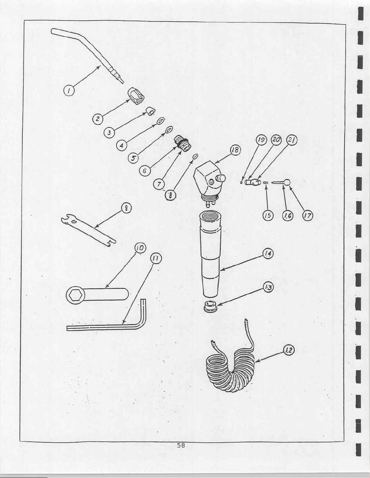

Ref.
No.
Description
SYRINGE
Part
No.
30-0040
Qty.
10
11
12:
13
14
15
16
17
18
19
20
21
1
2
3
4
3)
6
7
8
9
Syringe
Syringe
Cone**
O-Ring**
O-Ring**
O-Ring**
Threaded
O-Ring***
Sryinge
Wrench***
Hex
Sryinge
Straight:
Coiled:
Cap
Handle
Spring***
O-Ring***
Stem***
Syringe
O-Ring***
O-Ring***
Body,
Tool**
Allen
Tubing
Head***
Cartridge***
Tip,
Autoclavable*
Tip
Nut**
Barrel**
Wrench**
Black
Gray
Black
Gray
(**)
31-0004
31-0002
31-0007
31-0006
90-7310
1
1
1
1
1
1
1
1
1
il
1
1
1
1
ま
1
1
1
ji
1
1
1
1
1
*
4
==
Syringe
Syringe
Sryinge
Tips,
Autoclavable
Tip
Kit
Replacement
(Pkg.
Cartridge
of
Kit
5)
59
90-9210
90-8001
90-8005

AIR
COOLANT
TO
(2
PLACES)
HANDPIECE
WATER
COOLANT
(2
PLACES)
TO
HANOPIECE
“WATER
*
AIR
COOLANT
*
DRIVE
COOLANT
sen
&
PR
PILOT
AIR
#2
PILOT
AIR
#1
*GAUGE
DRIVE
AIR
TO-HANDPIECE
(2
PLACES)
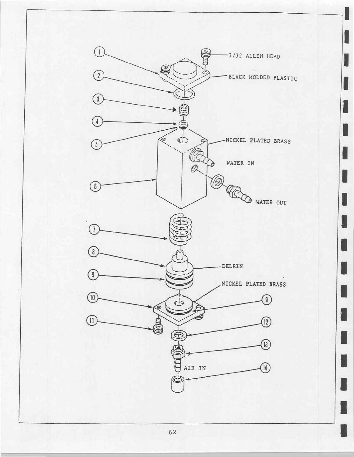
3/32
ALLEN
HEAD
BLACK
NICKEL
WATER
MOLDED
PLATED
IN
>
WATER
PLASTIC
BRASS
OUT
DELRIN
NICKEL
PLATED
BRASS

WATER
RELAY
VALVE
30-0300
Ref.
No.
다
DOLAR
AUNHO
m
Description
End
Cap
O-Ring*
Spring
Poppet*
O-Ring*
Valve
Spring
Plunger*
O-Ring*
End
Cap
Plastic
Barb
Barb
Repair
(Poppet)*
Body
(Plunger)*
Cap
(Input)
Screw,
Washer
Fitting,
Ferrule,
Kit
4-40 x 1/4"*
1/16" x 10-32
Small
(Water
Relay
Valve)
Part
No.
13-1580
33-1500
33-1600
90-8180
©
<
pd
pd
pp
UI
FR
he
ta
tato
63

64

COMPRESSOR
Ref.
20
21
22
22A
23
24
25
26
27
28
29
30
31
32
33
34
35
36
37
38
39
1
2
3
4
5
6
7
8
9
10
11
12
13
14
15
16
17
18
19
No.
Description
Hose
Coupler
Pins,
Filter*
Screen*
Intake
1/4"-
Head
Gasket
Valve
O-Ring*
Connecting
Cylinder
Fan
Screw
Screw
Eccentric
Nut
Isolators
Motor
Bolt
Capacitor,
Capacitor,
Capacitor,
Screw,
Fan,
Connector,
Flared
Heat
Flared
Connector,
Check
Street
Connector,
Nut,
Nipple
Pressure
Compression
Tubing,
Pressure
Assembly,
3/8"
Filter
Muffler
20 x 1
Plate
Sleeve”
Blade
#10-24 x 3/8"
Set,
Assembly
5/16"
5/16" x 1
Start
Run
Cover***
3/8"
1/2"
4
Nut,
Exchanger,
Nut,
Valve
Tee,
Compression
1/4"
Hex
Switch
1/4"
Switch
1/2"
ID,
Body x 3/8"
1/4"
Bolt,
hex
Assembly
Rod
1/4"-20 x 3/8"
1/4",
Metal***
1
Sg.,
Aluminum
Aluminum
1/2"
Brass
1/2"
MPT
1/2"
with
1/2"
MPT
1/8"
Reducer,
with
Nut,
Copper
Cover**
(includes
Assembly*
Hex
Hex
DP,
1/5"
3/8"
Aluminum
1/2"
1/2"
x
Unloader,
1/2"
x
1/2"
Unloader**
1/4"**
8"
10
ft.
FPT
head
valves
head
Head
115V
MPT
MPT
x
Brass
1/2"
Compression
x
restrictors
16W/.19A
Flared
1/2"
Flared
MPT
1/4"
Fitting
MPT
screws)
No.
Part
90-9125
33-1033
30-2065
09-1200
13-2507
09-1150
13-0210
07-4000
13-0375
09-1125
09-1310
09-5110
13-2425
13-2096
07-4010
13-1235
09-1010
20-0100
13-2508
90-4510
90-4512
90-6325
20-3400
33-4135
33-4335
13-8025
33-1335
33-1135
30-2125
33-1005
33-1104
33-1305
33-1159
Qu.
1
1
2
1
1
4
1
1
1
1
1
E
1
1
1
1
4
8
1
4
1
1
1
4
1
ih
1
1
1
1
1
1
1
1
4
1
I
1
1
*
pe
ses
Compressor
Pressure
Motor
Repair
Switch
Assembly
Assembly
Kit
65
90-9100
20-6007
90-9110

FIELD
UNIT
ELECTRICAL
DIAGRAM
6
per
Sele
=
E
У
W
[77
BN
EN
2
a
MODEL
o
8
NUMBER
Bl
8
>>
=
NSS
SE
>
>>.
P|
[77
2100M
TO
ELECTRICAL
PANEL
CN4
e
NES
т
©
>>
4
s
5
VA
в
<<
<<
=
<<
<<
<P
в
[TÅ
COAPRESSC
AJ
COMPRESSOR
B=BLACK
BL
=BLUE WIRE:
W=WHITE
G-GREEN
14
18
GAUGE
GAUGE
BN=BROWN
R=RED
0 = ORANGE
PARTS
AI
-COAPRESSOR 1 1/2
S4-PRESSURE
LIST
[15/230
VAC
50/60
SVITCH
EN4=CONNECTOR 9 PIN
622V
600\
HP
Hz
DPST

FIELD
E
E
ER
G
>
D
“어어
o
r
©
“à
N
op
m|
>|
5
ge
B|
=
>
no
da
HO
0>
mena
030>-
si
Ji
四
=
=
и
О
DODDO
一
we
QoSIQ
ロ
—NMMSIO
000000
иниииы
eee
FW
=O
IL
YULJO
VPI
<-
0
Ш
HF
FERRO
SOLOS
Ош
were
αἱ
эф
> <
«ικα.
|
EE
UNIT
x
O
OW
QUI
DU
s
mW
J
=
<
Z
uJ
MEME
Un
Olul<
WWWO
0000
x
OOGÇOOMM
(00000
<OOO=5
MODEL
O
Li
E
<
Wo
©
—0
=
qo
LODO
«κα
O
O
—
U0OODOO
MOOOO
Ш
AnLODO<X<
ONO]
<<<<0
se
NE
ZW
O0
ELE
N
т
O =
a
Lu
O
す
ο
ZZZU
ココ
ーー
ジ
ーー
FKEKXOO
ご
〇
ビビ
DOG
=)
O
©
O
0
509-
CONST
x
O
—
E
S
>
8
wW
J
OA
osssy
Ш
SE
si
=
m
o
LO
m
N u
Qu
一
,
:
-S
SEXYOVA
ONU
—
MM
ZN
tu
MAMA
MM
MS
YAN
LION)
MA
M0
DUST
00
Ul=0P-AMP
QI-=TRIAC
Q2
VV
-
SUN
VOSS
θελα
VOVYNSI
δν
de
TRIAC
900
NXNUNW=—NN-N-—LIN—
ONUNU
WeWWWee
DE
NUL
020500
=
We
L
М
JUN
ra.
OL
LU
=
©
DUAL
NTE5625
L4B1E3
0
—-WMM—
O
MODA
ao
00202
OOO
000
ヒ
に
に
の
Qe
の
に の
00000
po
O=O
ZON)
ビビ
=p
の
に
COMPARATOR
ビーー
ὦ
テテ
テー
NN
ニー
RSS
ペー
NE
LUE
=
a
67
ヒヒ
AE
ο
ZZN.
지자
SN
VEN
SUN
wo
>
=>
=
=
z
一
x
<
N
<
о
の
>
CA3290E
ul
©
Ul
に
0)
E
о
n
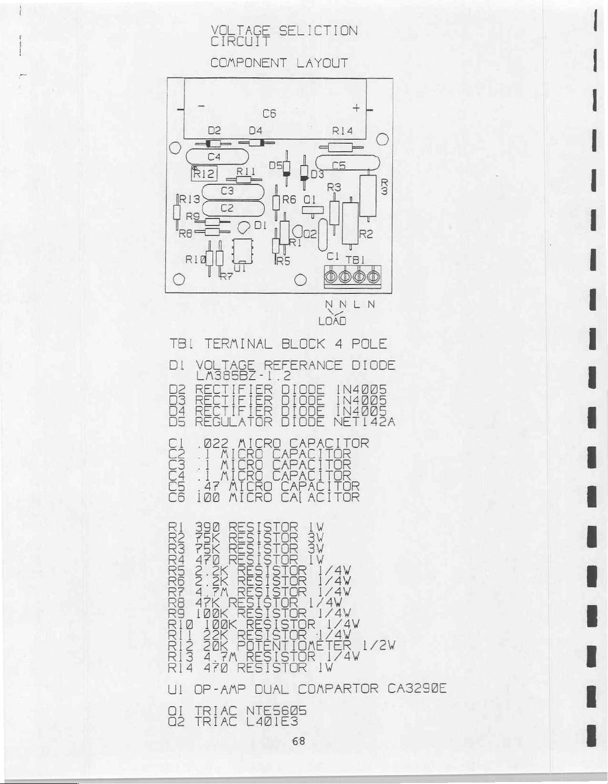
SO
O
E)
=
E
そつ
O
Z
fo
we
(=
EO
JE
Or
주
の
=
i
m
=
<
O
=
=
o
E)
=
6
+
=
O
コ
=
一
“ДО
D
J
Wo
LVNODDA
uy
eee
©
O000
F
O<Ullull]
>)
O
=
NOS
0000
JMO00O
irao
Z
<=
비실
ODuuu<
Ont
=
fe
Li
H
=
D
CE
OOO
<<<<a_
0000
E
OOOOM
TOO
<O000——
VUE
м
ωωωωωω
00507
(ИСИ
СИС
Ov
一
NmALOOD
一
Oh
一
QSLuD(Oh-O
TANT
の
—
ーーーーー
DTM
———xx
호
ко
|
VEN
OVYVONNNYGONG
O0
мм=
:
-
MONT
Ev
MSXXNS
e
M
μμ
μια
wn
©
IODO
LOL
O
LU
<<
KOLU
QO
A
|
FFLFOBOOKOFO-FO
ビビ
OOOOFFFOFUrFEUF-
OOnono
tati
ビビ
ton
の
DANNI
の
の
ビ
OOO
の
ーー
の
DA
ーー
の
X
о
O
Z
<
ts
ΩΩΩΩ
ORRR——
LOU)
αώώως«ς
NM
Е
=
때
Ш
<
O
L
©
ο
Ш
oso-
==
ZZZU
SY-
q
OO,
Frrro6
©
CO
>>>
ААП
24204
=
si
=
LU
то
A
WwW
юоюм
asası
<
= O
N
>
2
OO
=
—N
19
}
가
-
a
1
——
Fr
<
<<
&
0
Zo
@
Ех
£
I
Da
WS
J
So
Οι!
©
О
м
o
O
=
©
比
=
ο
x
<
m
N
の
©
Lu

σι
TO
COAPRESSOR
$
of
УМУМУУМУУ
АЛАЛАЛАЛЛ
E
[
У
SEE
SSRI
ODI
HU
CIRCUIT
«SOLID
NINE
C
É
ER
STATE
¡DON
BOARD
2388
<<
os
BP
Ret
FOR
CONPONENT
ss
PART
LIST
=
RELAY
2300
ZZ.
249VAC
59AAP
van
UO,
E
>
ロコ
DDT
poco
ezildi
SE
VH
REEN
vsi
18
АЕ
GAUGE
600
600
у
CONPRESSOR
ELECTRICAL
PANEL
FIELD
UNIT
MODEL
[
F
ES
7
내
o je
|
TO
DELIVERY
AODULE
マ
レツ
ソソ ツ ソソ
So
NANNANA
し
gl|
в
ma
slm|
<=
uv
<lsl
в
58
g
É.
μα.
ELECTRICAL
NUMBER
2180
DIAGRAM

COMPRESSOR
MODULE TUBING
DIAGRAM
PRESSURE
SWITCH
AIR
OUT
00
WARNING
O
NOT
D
W
ITH
I
NSTALLED
ALLOW
B
EFORE
=
P
C
Е
L
X
SONNEL
VICES
1/2°0D
1
i
CL
i
|
1453
CHECK
VALVE
(Bi
-
RUN
OUT
END
COMPRESSOR
SERVICING.
CAUT
REVENT
K
MAKE SURE
R
SUPPLY
UGGED
AUTHOR]
ALLOWED
THIS
COMPRESSOR
PANELS
TON
ELECTRICAL
HAS
FROM
ALUMINUM
UNTT.
ZED
UNIT
TO
BEEN
TO
TUBE
COOL
COMPRESSOR
70

=
Es
E
ire
alii
92
GA
Ep
|
©
©
DRIVE
COOLANT
AIR
VATER
Biro.
@®
COOLANT
AIR
<
LEGEND
AIR
FLOV
map
때
|
Mp
man
FIBER
OPTIC
BLACK
DELIVERY
MODULE
AIR
ELECTRICAL
DIAGRAM
a
em
ΙΙ
DR
mm
ma
)
GS
SME?
sila
10/32
1/4"
1/87
QUICK
CHECK
QUICK
DISCONNECT
VALVE
DISCONNECT
만
10/32
TEE
1/4700
(6.
35mm
)
->
19/32
CROSS
TUBING
1/870D
(3.
175mm)
71
==
CONTROL
6605
PANEL

FIELD
ZAN
JO
ΆΛΛΛΛΛΛ
ANIN
ANIN
TO_COMPRESSOR
ELECTRICAL
PANEL
UNIT
MODEL
VVS
BL
VAVAVAVAVAVI
ZN
G
ELECTRICAL
NUMBER
502
V
a
PINT
CABLE
DIAGRAM
2120A
BL
y
ν
CNI
52
Z
FOCI
MO
EC
SI
sol
P.O
TA
Oe
DELIVERY
09000000
ии
пин
OOS
HA
SONO
ZZNOOO
UT
Ju
SHOW
ANJO)
un
"
MODULE
テー
TRE:
8
72
GAUGE
622
V

ME
ER
AVd9
(Ap
am
am
WVYOVIO
WONOVA
SINGOW
MV
DİLİ
gloN3n05
Aveo
Wow
b
få
AV
YIULSINVI_WMNDVA.
Mae
ou
‘
x
EMV
BISVA
INV
HaLVA
AO
op31
у
P
001J
HIVA
κ
334
28/01
に
(uuccey
AYSAITSG
TENYA
NON
Ap
때
1en
RER
tuusz1"£)
{UUSTS'68)
(0.
vadě
ZI)
lle
00.9
qu
=]
ΑΛ
vedar
εμας
τα)
ONIgrL
004
00,871
73

——
EE
EE
DNS
DIGITO
NUIT
VVUOVIO
NIVYO
vio
060
ÉTAT
BLY
ANIMA
RE
NIVIO
au
3M00W
AUSA1TIO
Nd
730
BISWA
ONY
(wuz¿1"€)
LISE
UBIVA
"91
ONIENI
00.+/1
00.8/1
19209610
oan
sou
uy
[>
Aou
vam
>
лам
хан
гели
+
3AWA
30ino
20310
2ze/61
,r/!
~
css
EE
EZ
EZ
EZ
EZ
EE EŞ EE EE
TINI
DUNDI
Ez
EE Ez
mz
=
Em
74

TEME.
DELAY
(C1RGU
T
COMPONENT
fu]
it
I]
je
메리
l
TRACE
|
TOP
us
LAYOUT
ONTL
Φ
o o
De”
©
VIEW
TRACE
06
마
005
D7
MC7805CT
C
Č
R1I6.R17
R18
U2
U3
000
8
330
MOC3020
SN74123N
BOTTOM
BRIDGE
MIC
220
MICRO
22K
RESISTOR
VIEW
RECTIFIER
VOLTAGE
e
CAPAC | TOR
CAPACITOR
RESISTOR
1/4W
OPTOISOLATOR
MONSTABLE
REGULATOR
1/4W
TRIAC
MULTIVBRATOR
2760
RIB
 Loading...