

Compressed Air Advisors MH-US-15, MH-US-25, MH-US-35, MH-US-50, MH-US-75 Instruction Manual
...
COMPRESSED AIR DRYERS
INSTRUCTION
MANUAL
MH-US SERIES (MH-US-10 to MH-US-100)
WARRANTY NOTICE
Failure to follow the instructions and
procedures in this manual or misuse of this
equipment will VOID its warranty !

Page 2

TABLE OF CONTENTS
1. IMPORTANT SAFETY NOTES - Please read ........ 6
1.1. Transportation ............................................................. 6
1.2 Positioning ................................................................... 6
1.3 Installation .................................................................... 6
1.4 Before operating ........................................................ 6
1.5 Qualified service personnel .................................... 7
1.6 Maintenance by the user ......................................... 7
2.
INTRODUCTION TO THE MHUS DRYER ............ 7
3.
OPERATION .................................................................. 11
4.
ELECTRICAL CONTROLLER ................................... 13
4.1 Digi-Pro ......................................................................... 13
5. TECHNICAL SPECIFICATIONS.................................16
6. DIAGRAMS..................................................................... 17
6.1 Air Flow Diagrams....................................................... 18
6.2 Electrical Diagrams..................................................... 24
6.3 Electrical Diagrams..................................................... 26
7.
GENERAL ARRANGEMENTS..................................... 34
8. EXPLODED DIAGRAMS ............................................. 34
9.
COMPONENTS LOCATION..................................... 48
10. TROUBLESHOOTING ................................................ 49
11. WARRANTY .................................................................. 51
Page 3

Declaration of Conformity
PED 2014/68/EU
(NB No : 0408)
Manufacturer Mikropor Filters
I.OSB Büyük Selçuklu Caddesi, No:4 06935 Ankara/Turkey
Phone: 0312 267 0770
Fax: 0312 267 0552
Product Description
Serial No of Set (device)
Type of Product
Module
Assesment Modele
Confirmed By
TÜV Austria Service GMBH
Kind of inspection certification supplied standards
Certificate No:
Modules for compatibility assesment of pressure in-build elements;
Exchanger
Receiver
Separator
Compressor
Air Dryer
MH-US-15, MH-US-25, MH-US-35, MH-US-50, MH-US-75
MH-US-100
0118MA00001 to 5218MA99999
CAT II Air Dryer
Module A2
Module A2 type compatibility
Notified Body No 0408
Addres; Deutschstreasse 10 1230 Wien/Österreich
PED (2014/68/EU) Certification EN378-2
ZSTS / SWZE / 1790
CAT II MODUL A2
CAT I MODUL A2
CAT I MODUL A2
CAT I MODUL A2
Product Responsibility Mikropor Filter is responsible for product in conditions it
was delivered. Any modifications are forbidden.
Product be operated according to its application. In case
of breaking above conditions realized manufacturer from
responsibility for the product CE mark of the product will
be not valid.
Signature
Local Quality Manager, Pressure Vessel Ahmet Emin ÇAMLIBEL
Date; 29.03.2017
Page 4

EC DECLARATION OF CONFORMITY
MANUFACTURER
NAME : MİKROPOR MAK. SAN. VE TİC. A.Ş.
ADDRESS : Organize Sanayi Bölgesi Büyük Selçuklu Bulvarı No. 4, 06935, Ankara - Türkiye
TEL : +90 312 267 07 00 FAX: +90 312 267 05 52 WEB: www.mikropor.com.tr
Name and Address of the
Person authorised to compile the technical file
Organize Sanayi Bölgesi Büyük Selçuklu
Bulvarı No. 4, 06935, Ankara -Türkiye
The undersigned declares that the described products meet the essential requirements of the below
mentioned standards as based on Machinery Directive 2006/42/EC, Low Voltage Directive 2014/35/
EU, Electromagnetic Compatibility Directive 2014/30/EU
The item of equipments which identified below has been subject to internal manufacturing checks
with monitoring of the final assesment by Mikropor
MACHINE DESCRIPTION MODELS : Air Dryer
: Ahmet Emin ÇAMLIBEL
MH-US-15, MH-US-25, MH-US-35, MH-US-50, MH-US-75, MH-US-100
Serial No of Set (device): 0118MA00001 to 5218MA99999
APPLICABLE DIRECTIVES :
2006/42/EC MACHINE SAFETY DIRECTIVE
2014/35/EU LOW VOLTAGE DIRECTIVE
2014/30/EU ELECTROMAGNETIC COMPATIBILITY DIRECTIVE
Certificate No: 16-PS-0279-TAT-16-MAD-1059
APPLICABLE REGULATIONS :
EN ISO 12100:2010; EN 60204-1:2006/AC:2010; EN 61000-6-2:2005; EN 61000-6-4:2007+A1:2011
EN 378-2
SIGNED ON BE HALF OF THE MANUFACTURER
NAME : Mustafa Uslu
POSITION : R&D Manager
PLACE/ DATE : ANKARA / 03.04.2017
SIGNATURE :
Page 5

I. IMPORTANT SAFETY NOTES Please READ
When operating the air dryer the operator must apply safe working methods and observe all local
safety instructions and relevant regulations.
A Prior to installation, the dryer and the compressed air system are to be depressurized and
disconnected from the electrical main supply.
B The user is responsible for safe operating conditions. Parts and accessories must be replaced if
inspection shows that safe operation cannot be assured.
C Installation, operation, maintenance and repair are only to be authorized, trained and skilled
engineers.
D The minimum and maximum values stated must be observed, as well as all of the safety precautions
described in this manual.
E If any statement in this manual does not comply with the local legislation, the strongest standard is to be
applied.
1.1. Transportation
A Use care and caution when transporting the dryer. Avoid dropping and other physical abuse.
B A forklift can be used to transport the dryers provided the forks are long enough to support its full width
or length and caution is used throughout the move.
1.2. Positioning
A The dryer must be installed horizontally. A minimum of 19.6 in. clearance around the dryer is necessary
to allow a good ventilation and easy access for servicing.
B The ambient temperature in the room should not exceed 113°F and should not be below 39.2°F, taking
the heat radiated by the dryer into account.
C (40 watt for each liter/sec under ISO 7183-A condition or 18 watts for each SCFM under ISO 7183-B
condition).
D There should be no chemicals in the atmosphere that will damage the copper source. (Ammonia gas
etc.)
1.3. Installation
In addition to the general mechanical construction procedures and local regulations, the following
instructions need to be emphasized:
1 Only authorized, trained and skilled engineers should install the compressed air dryer.
2 Safety devices, protecting covers or insulation in the dryers never to be dismantled or modified.
Each pressure vessel or accessory installed outside the dryer with air above atmospheric pressure must be
fitted with the required pressure relief safety valves.
1.4. Before Operating
The following points must be observed before operating the air dryer:
A Review all safety precautions.
B The dryer connection piping measurements must be selected correctly. (See Technical specifications)
C The dryer connection piping must be adapted to the operating pressure. (See Technical specifications)
D Never operate the dryer at pressure above the maximum specified on the dryer label (check the
technical specs too).
E The drains should be opened to atmosphere. If the drains are connected to a pipe / hose, the diameter
of the hose / pipe should be large enough to create no back pressure during drain. It is not recommended
to reduce the diameter of the hose / pipe less than port that is given at the drain outlet of the unit.
The hose / pipe should be at atmospheric pressure at all time. Back pressure in relevant pipe will result in
permanent damage on drain system and the aect function of the filters and / or dryers.
Page 6

1.5. Qualified service personnel
A Maintenance and repairs should only be performed when the air dryer is shut down and depressurized
and when the main power switch is turned o.
B Use only the appropriate tools for maintenance and repair.
C Before dismantling a part under pressure, disconnect the pressure sources and depressurize the
system.
D Proceed carefully during maintenance and repair. Prevent dirt from entering by covering parts and
orifices with a clean cloth, paper or tape. A receiver should never be welded or modified in any way.
E Never leave tools, loose parts or cleaning rags in or on the air dryer.
F Before returning the dryer into service, check the setting of the control and safety devices as well as the
pressure and the temperature of the compressed air circuit.
1.6. Maintenance by the user
A Keep the dryer clean.
B Regularly check the correct operation of the condensate drain trap.
C Every six months, check and clean the drain strainer by undoing the access screw and rinsing the filter
with tap water to remove the trapped dirt from the inside.
D For aircooled dryers, clean the air condenser as soon as it’s dirty or clogged.
E For optional water-cooled condensers, use only clean water andinstall a water filter if needed. Use
water counter flow to clean condenser if need.
F Check the trouble-shooting list in case of maintenance troubles.
G Check operating pressures, temperatures and time settings after maintenance. If operating and safety
devices function properly, the air dryer may be used.
2. INTRODUCTION TO THE DRYER
A) Manufacturer:
MiKROPOR / www.mikropor.com
B) Purpose of this dryer
1 This refrigerated compressed air dryer has been designed to remove water vapor from industrial
compressed air.
2 This dryer has been designed for indoor operation.
3 The minimum and maximum values stated must be observed, as well as the safety precautions
described in this manual.
Page 7

C) Dryer label
The following label is axed on the cabinet of the refrigerant compressed air dryer.
Dryer label describtions
Max. Refrigerant Pressure
Max. Air Pressure
Max. Air Inlet Temp.
Min. Ambient Temp.
Max. Ambient Temp.
Min. Circuit Ampacity
Max. Protective Device Rating
Mikropor America Inc.
251 N.Roeske Avenue Michigan City, IN 46360
www.mikroporamerica.com
Voltage
P Rating
Refrigerant R134a
Weight
Fan
Compressor
MODEL NO: MH-US
SERIAL NO:
MH-US
Model No: Dryer model no
Serial No: Dryer serial no
Max Refrigerant Pressure: Dryer maximum working pressure
Max. Air Pressure: Maximum air pressure
Max. Air Inlet Temp: Maximum air inlet temperature
Min. Ambient Temp. : Minimum ambient temperature
Max. Ambient Temp. : Maximum ambient temperature
Min. Circuit Ampacity : Maximum allowed amount of current
Max Protective Device Rating : Maximum protective device rating
Voltage :
IP Rating : Protection rating
Refrigerant 134a :
Weight : Dryer weight
Fan : Model of fan used
Compressor : Model of compressor used
D) Working details
1) Refrigerant circuit:
The refrigerant circuit can be divided in 3 parts:
Main supply voltage
Amount of refrigerant gas used
A Low pressure section with an evaporator (heat exchanger)
B High-pressure section including: Condenser, liquid receiver, (if installed) and the filter dryer.
C Control circuit including: Compressor, Expansion valve, by-pass valve (if installed),
Fan pressure switch (if installed)
2) The Refrigerant circuit operates as follows:
A The compressor compresses gaseous refrigerant to a high temperature.
B The hot refrigerant condenses in the condenser. Being liquefied it is stored in the liquid receiver (if installed).
C The liquid is taken out the storage vessel and injected in the evaporator (heat exchanger) by an expansion valve.
This expansion valve is protected by a filter, which removes particles and humidity that could be in the circuit.
D The injected liquid fills in the refrigerant section of the air / refrigerant heat exchanger and evaporates by taking
out the calories from the compressed air. The gaseous refrigerant is sucked in the compressor and the cycle carries
on.
E In order to keep the evaporation pressure steady, and thus the refrigerant temperature in the heat
exchanger, a by-pass valve is injecting hot gaseous refrigerant in the circuit. On certain dryers, an
automatic expansion valve regulates this.
3) Compressed air circuit:
A The saturated hot compressed air flows into the Economiserwhere it is pre-cooled by the out flowing dry chilled
air. In the cold zone of the air refrigerant section it continues to cool down to dew point and enters the separator
where condensates are collected. The outgoing chilled air is then warmed up in the economizer by the hot
incoming air.
Page 8

B The condensates are collected after centrifugal separation and drained out through the automatic trap.
C As long as the compressed air temperature does not drop below dew point, there will be no
condensation in the air circuit.
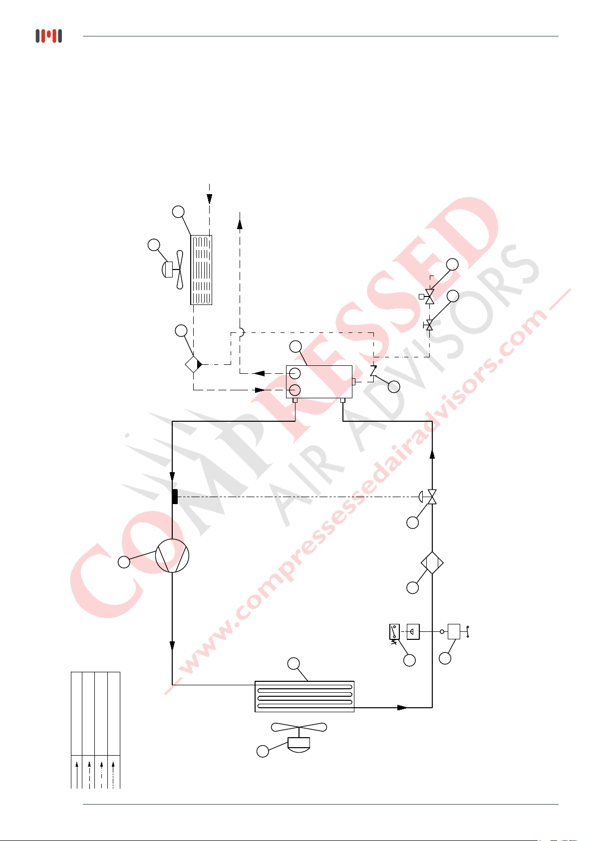
Compressed Air Dryer Working Principle
Compressed
A
B
L
J
B
C
D
H
F G
E
I
K
A-COMPRESSOR
B-FAN MOTOR
C-CONDENSER
D-HIGH PRESSURE SWITCH
E-FAN SWITCH
F-FILTER DRIER
G-EXPANSION VALVE
H-CHECK VALVE
I-SOLENOID VALVE
J-HEAT EXCHANGER
K-AFTERCOOLER
L-WATER SEPARATOR
Refrigerant Gas Flow Line
Compressed Air Flow Line
Drain Flow Line
Dry Air Outlet
Compressed
Dry Air Inlet
4) Refrigerant compressor
Increases the pressure and temperature of refrigerant. There is one type of compressor commonly used
according to refrigerant capacity on this application which is Piston Type.
5) Condenser
Dissipates the heat provided by evaporator and compressor.
There is one type of condenser used on the application:
- Air Cooled Type (standard)
These condensers are designed to dissipate the heat to the ambient air.
The fans are used to force the air flow through the fins to enhance the heat transfer.
6) Refrigerant circuit protection
A Klixon: The single phase compressors are equipped with a klixon which is a thermal sensitive switch
controlling the temperature of the compressor and possible overintensity.
In case of malfunction, the klixon trips but switches on again automatically as soon as the compressor has
cooled down.
B High Pressure Security Switch: Refrigerant line is considered as a pressure vessel. That is why it is
protected against bursts by the help of manually reset switch. It is set to 362 psi for dryers working with R134a
C Filter dryer: A refrigerant circuit is a closed circuit and total water removal in the refrigerant circuit is
paramount in order to obtain a correct functioning.
D To avoid problems, the refrigerant circuit must be vacuumed before loading the refrigerant.
It is equipped with a filter dryer, which also traps any solid particles, which may have migrated into the circuit during
assembly.
E Water-cooled dryers have a safety high-pressure switch.
In case of cooling water failure, the safety switch stops the dryer. When the safety switch has tripped out,
it has to be manually resettled before switching on the dryer.
Page 9

7) Refrigerant circuit controls
A Liquid refrigerant injection: The liquid refrigerant is into the evaporator by a control valve. This valve is a
thermostatic or pressostatic one maintaining a constant overheats of the refrigerant in the evaporator(s).
B Constant evaporating pressure: In the dryers equipped with a by-pass valve, the evaporating pressure is
kept constant by a controlled injection of hot gas from the high-pressure side into the low-pressure
section of the circuit.
8) Condensate drain - trap assembly
Dismantling the drain is easy because it can be isolated from the air circuit under pressure with a ball valve.
The drain has to be depressurized before being dismantled.
9) Heat Exchanger Modular design
AThe dryers are equipped with a compact
Mono Bloc Heat Exchanger module.
This assembly has been specially designed to
dry compressed air and is made of:
1 An Economiser which pre-cools the
entering hot air with the out flowing cold air.
2 An air/refrigerant exchanger cooling down
the compressed air.
3 A centrifugal separator concentrating all
condensates and requiring no maintenance.
10) Accessories
Temperature switch: Temperature switch: Located inside the dryer, this temperature switch is adjustable
from 32°F up to 95 °F.
Digital Controller –DigiPro: This device helps dryer save energy when there is not any compressed air flow
in the dryer. Those information can be reached; Dewpoint value, periodic maintenance interval display,
status report, run time meter, temperature unit selection (°F or °C)
Page 10

3. OPERATION
Control panels for MH-US Series
The control panel of the dryer includes the following elements:
Monophase Digital Controller
MH-US-15 - MH-US-100 Digi-Pro
IMPORTANT NOTE
The Dryer has two Compressed Air Filter inside.
It is better to change filter element for the best eciency when the alarm status is active.
It is recommended to keep replacement filter elements in your stock in order to replace them when needed.
ATTENTION
MH-US range dryers have low pressure drop according its competitors.
Do not use MH-US range dryers together with other dryers which have higher pressure drop
without getting the confirmation from our technical team.
Page 11

3.1. During Operation
Regularly check the digital temperature controller ESD3 or Digi-Pro on dryer.
3.2 Start up and shut-down
Warning: Avoid leaving the dryer o when compressed air is still flowing through it.
3.3 Starting for the first time or after a long stop
1 Set the rotary switch to “I” This preheats the dryer and turns the drain system on.
It is recommended to leave the dryer power on permanently so the crankcase heater runs continuously.
IMPORTANT NOTE!
2 After a long stop of the dryer it is MANDATORY to allow a preheating period of minimum 4 hours
before starting again, to avoid any compressed air flow during preheating.
3 Follow the daily starting and shut down preocedure.
3.4 Daily starting and shut-down
1 Push on the ON button to start the dryer.
2 The start light or Dryer Active will indicate that the dryer is running.
3 To stop the dryer, first stop the airflow (either shut-down the air compressor or close the inlet/outlet or
by-pass valve) When the air flow is stopped, set the rotary switch on “ 0 “ Set it again on “ I “ in order to keep the
preheating on.
IMPORTANT NOTE !
4 Avoid leaving the dryer stopped when compressed air is still flowing through it.
5 To switch the already preheated dryer on again, simply push the green start button.
Page 12

4) ELECTRICAL CONTROLLER
4.1 DIGI-PRO
4.1.1 Description
With the Digi-Pro series controllers, air dryers have outstanding technology for both functionality and
dynamism, as well as appearance. The multi-functional display provides an accurate digital dew point
display as well as coded alarm monitoring of the refrigerant dryer.
DIGITAL CONTROLLER ADVANTAGES;
• Digital dew point monitoring
• Energy-saving mode display
• Periodic maintenance interval display
• Status report
• Run time meter
• Fahrenheit and Centigrade selection
4.1.2 Operation
Using the Digi Pro controller as shown in the picture below:
4.1.3 Menu Buttons
PROGRAM
To modify the parameter, press and release button set. The menu
is used by service team. To disable the Key Lock: Press and hold
the SET for 4 sec.
POWER
MENU
MANUAL DRAİN
This button is used for starting and stopping the dryer. Press and
hold for 4 seconds to start or stop.
These buttons are used to navigate between screens and adjust
values.
This button is used for manual control of the drain output. Press
and hold for 4 seconds to drain manually.
Page 13
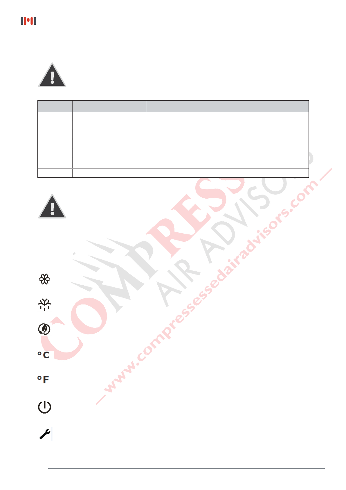
4.1.4 ALARM DISPLAY
Alarms / warnings are displayed on the digital screen. That means the dryer is not working
under normal operating conditions, which are outside the range of set values.
Alarm Code Alarm Description Reason for Alarm
tAL Low Temperature Alarm Refrigerant line temperature is lower than specified set values
tAH High Temperature Alarm Refrigerant line temperature is higher than specified set values
FIL Filter Change Alarm Filter element needs to be replaced
SEr General Service Alarm General service time of the dryer
HPr High Pressure Alarm Refrigerant high line pressure is higher than specified set values
Pr1 Temperature Probe Alarm Temperature sensor is faulty.
hFI Working Hours Alarm The dryer working hours allowed has been reached.
Please contact to the service when an alarm/warning occurs.
4.1.5 MODE DISPLAY
DRYER ACTIVE MODE
This mark indicates that the dryer is performed in active state
and drying.
Shows if the drain system is activated.AUTOMATIC DRAIN MODE
Shows if the energy saving mode is activatedENERGY SAVİNG MODE
Indicates that Celsius temperature unit is selected.CELSİUS UNİT MODE
Indicates that Fahrenheit temperature unit is selected.FAHRENHEİT UNİT MODE
This mode shows that the dryer is ready for drying operation.COMPRESSOR STANDBY MODE
Page 14
This mode shows that the dryer in the service time.SERVİCE MODE

4.2 Operation Principles
In order to start the dryer, the following conditions must be satisfied.
1. All the temperatures except the exchanger temperature and condenser outlet temperature must
be between their low and high limits. The low pressure line temperature can be ‘HIGH’.
2. Digital Input 3 (Compressor Fault) is not activated.
3. Digital Input 4 (Compressor Overload) is not activated.
4. Digital Input 5 (Fan Fault) is not activated.
5. Digital Input 6 (Fan Overload) is not activated.
6. Digital Input 7 (Phase Sequence Error) is not activated.
7. Digital Input 8 (Remote Disable) is not activated.
8. Digital Input 11 (High Pressure) is not activated.
9. Digital Input 12 (Low Pressure) is not activated.
If all the above conditions are satisfied, the dryer can be started.
Page 15

5. TECHNICAL SPECIFICATIONS
Model Capacity
(scfm)
MH-US-15 15 1/2" NPT 115/1/60 R134a 1,6
MH-US-25 25 1/2" NPT 115/1/60 R134a 2,5
MH-US-35 35 1/2" NPT 115/1/60 R134a 2,8
MH-US-50 50 3/4" NPT 115/1/60 R134a 1,7
MH-US-75 75 3/4" NPT 115/1/60 R134a 2,0
MH-US-100 100 3/4" NPT 115/1/60 R134a 2,4
FOR ALL MODELS
Nominal Working Pressure 100 psig
Maximum Working Pressure 230 psig
Maximum Ambient Temperature 120°F
Maximum Inlet Temperature 240°F
Connection
Size
Voltage Refrigerant
gas
Pressure
drop
(psig)
Page 16

6.1
MHUS
AIR FLOW DIAGRAMS
Page 17

6.DIAGRAMS
REFRIGERANT GAS FLOW LINE
COMPRESSED AIR FLOW LINE
6.1 AIR FLOW DIAGRAMS
MH-US-15 - MH-US-25
10
AIR INLET
AIR OUTLET
2
M
S
11
12
9
8
S
13
1
DRAIN FLOW LINE
PILOT FLOW LINE
7
6
3
M
4
5
2
Page 18

6.1 AIR FLOW DIAGRAMS
MH-US-15 - MH-US-25
13 CHECK VALVE
12
11
10
9
8
7
6
5
4
3
2
1
POS.
MANUEL VALVE
SOLENOID VALVE
AFTERCOOLER
WATER SEPERATOR
HEAT EXCHANGER
EXPANSION VALVE
FILTER DRIER
FAN SWITCH
HIGH PRESSURE SWITCH
CONDENSER
FAN MOTOR
COMPRESSOR
DESCRIPTION
1
1
1
1
1
1
1
1
1
1
1
2
1
QTY
Page 19
6.1 AIR FLOW DIAGRAMS
REFRIGERANT GAS FLOW LINE
COMPRESSED AIR FLOW LINE
MH-US-35
10
AIR INLET
AIR OUTLET
2
M
S
11
12
9
8
S
13
Page 20
1
DRAIN FLOW LINE
PILOT FLOW LINE
7
6
3
M
4
5
2

6.1 AIR FLOW DIAGRAMS
MH-US-35
13 CHECK VALVE
12
11
10
9
8
7
6
5
4
3
2
1
POS.
MANUEL VALVE
SOLENOID VALVE
AFTERCOOLER
WATER SEPERATOR
HEAT EXCHANGER
EXPANSION VALVE
FILTER DRIER
FAN SWITCH
HIGH PRESSURE SWITCH
CONDENSER
FAN MOTOR
COMPRESSOR
DESCRIPTION
1
1
1
1
1
1
1
1
1
1
1
2
1
QTY
Page 21

6.1 AIR FLOW DIAGRAMS
REFRIGERANT GAS FLOW LINE
COMPRESSED AIR FLOW LINE
MH-US-50 - MH-US-100
2
M
10
AIR INLET
11
AIR OUTLET
S
12
9
8
S
13
7
1
Page 22
DRAIN FLOW LINE
PILOT FLOW LINE
6
3
M
4
5
2

6.1 AIR FLOW DIAGRAMS
MH-US-50 - MH-US-100
13 CHECK VALVE
12
11
10
9
8
7
6
5
4
3
2
1
POS.
MANUEL VALVE
SOLENOID VALVE
AFTERCOOLER
WATER SEPERATOR
HEAT EXCHANGER
EXPANSION VALVE
FILTER DRIER
FAN SWITCH
HIGH PRESSURE SWITCH
CONDENSER
FAN MOTOR
COMPRESSOR
DESCRIPTION
1
1
1
1
1
1
1
1
1
1
1
2
1
QTY
Page 23

6.2
MHUS
ELECTRICAL DIAGRAMS
With Control & Power
“User must supply the protective earth conductor of the dryer. The conductor is to be connected to
the point on the conducting body of the dryer, specified by a sticker with the protective earth symbol
next to it. The size of the protective earth conductor should be minimum the size of the power
conductor, minimum 16 mm² for power conductor size between 16 and 35 mm², minimum half the
size of the conductor if it is larger than 35 mm².”
Page 24

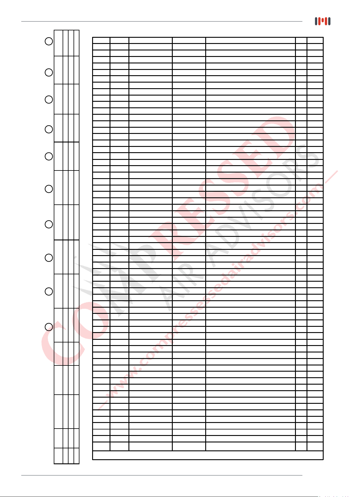
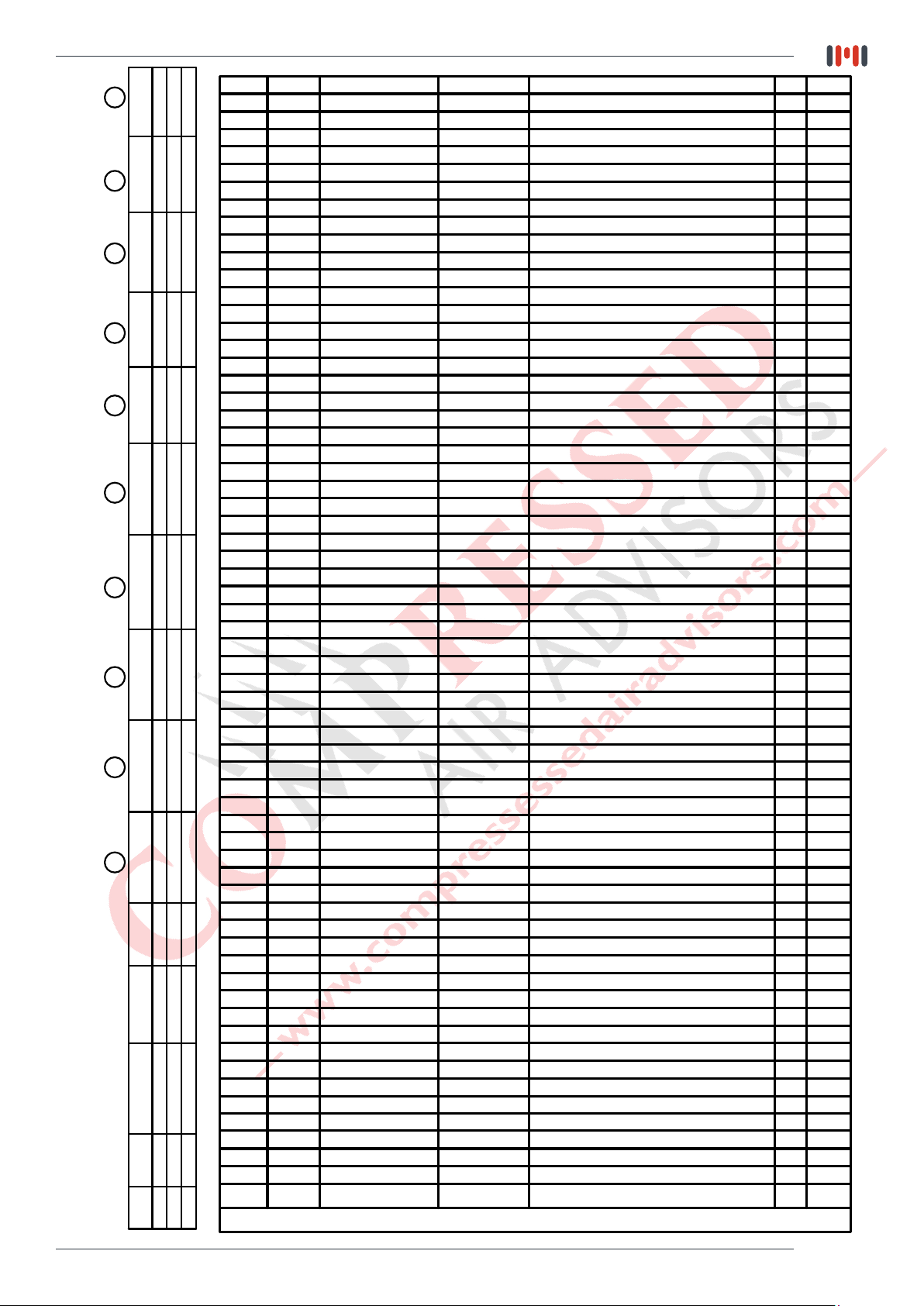
6.2 ELECTRICAL DIAGRAMS
MH-US-15 to MH-US-100
MODEL
MH-US-15 115/1P/60 0,69 7,45 8,6 IP 54 26 8
MH-US-25 115/1P/60 0,69 7,57 8,8 IP 54 29 8
MH-US-35 115/1P/60 0,88 9,61 11,5 IP 54 36 12
MH-US-50 115/1P/60 0,5 10,75 13,4 IP 54 46 15
MH-US-75 115/1P/60 0,95 11 13,4 IP 54 46 15
MH-US-100 115/1P/60 1,16 13,18 15,8 IP 54 51 15
Voltage/Phase/
Hertz
INSTALLED
POWER
(kWatt)
Nominal
Ampacity
(Amp)
MCA A
ELECTRICAL
PROTECTION CLASS
ACCORDING IEC
TOTAL
LRA A
Fuse
(Amp)
Page 25

6.2 ELECTRICAL DIAGRAMS
MH-US-15 to MH-US-100
Page 26
6.3
MHUS
ID DIAGRAM DRAWINGS &
GENERAL ARRANGEMENTS
Page 27
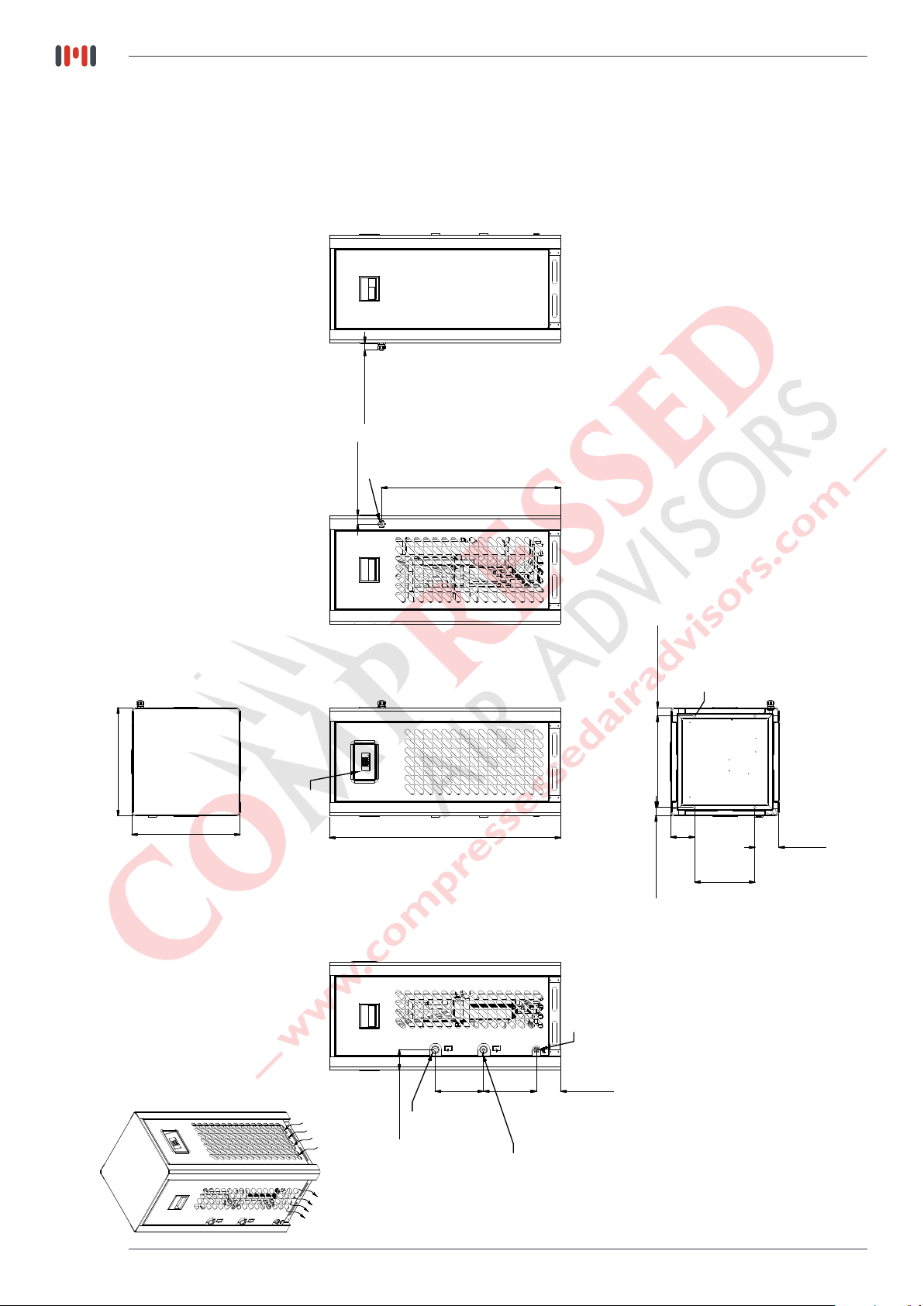
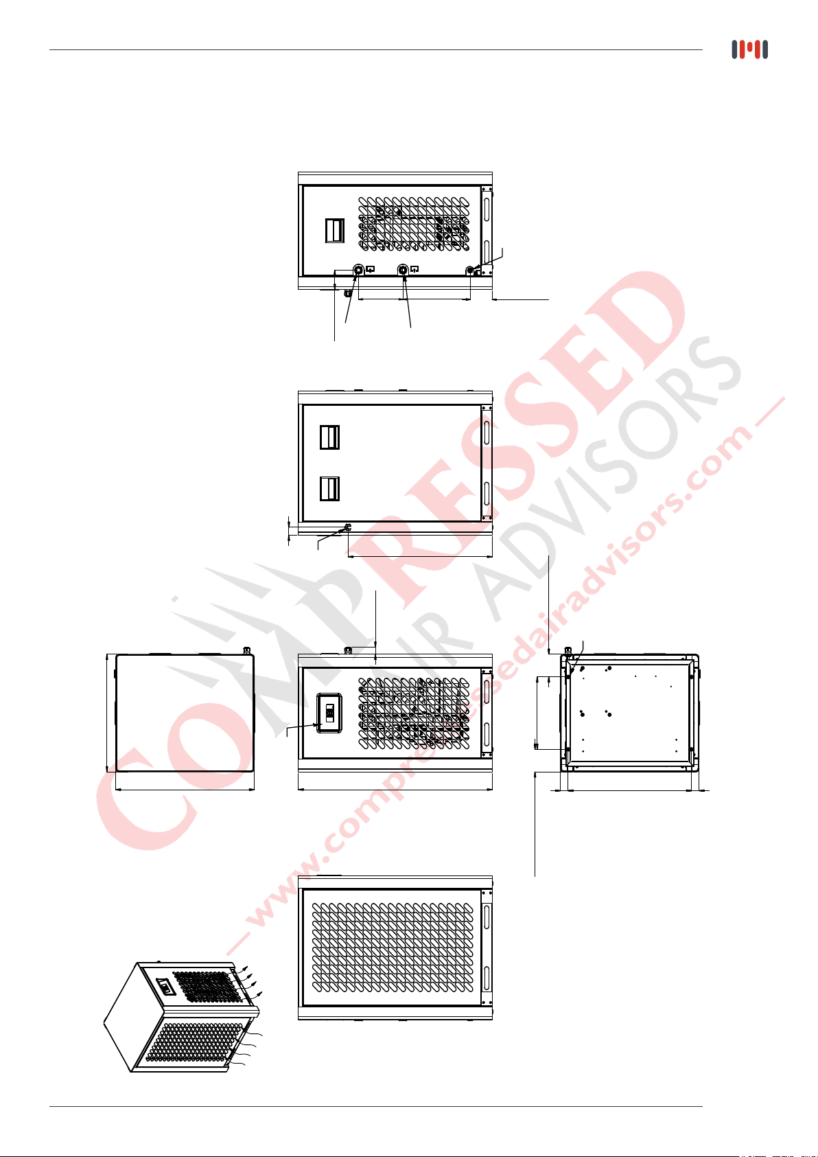
6.3 ID DIAGRAM DRAWINGS
3.89''
(99mm)
COOLING AIR OUTLET
MH-US-15
1.22'' (31mm)
1.37'' (35mm)
Cable
Connectıon
BACK VIEW
29.19'' (741,5mm)
17.61'' (447,5mm)
RIGHT VIEW
1.38'' (35,2mm)
(377,5mm)
14.86''
M8x4
TOP VIEW
FRONT VIEW
17.63'' (448mm)
Digital Controller
37.65'' (956,5mm)
Drain 3/8"
1.38'' (35,3mm)
NPT
(99mm)
3.89''
(250mm)
9.84''
BOTTOM VIEW
LEFT VIEW
Page 28
COOLING AIR INLET
3.30'' (84mm)
Air Outlet
1/2"
NPT
(200mm)
7.87''
(219mm)
8.62''
1/2"
Air Inlet
NPT
(100mm)
3.93''

6.3 ID DIAGRAM DRAWINGS
3.89''
(99mm)
COOLING AIR OUTLET
MH-US 25
1.37'' (35mm)
1.22'' (31mm)
Cable
BACK VIEW
Connectıon
29.19'' (741,5mm)
RIGHT VIEW
17.61'' (447,5mm)
1.38'' (35,2mm)
(377,5mm)
14.86''
M8x4
TOP VIEW
FRONT VIEW
17.63'' (448mm)
Digital Controller
37.65'' (956,5mm)
Drain 3/8"
1.38'' (35,3mm)
NPT
(99mm)
3.89''
(250mm)
9.84''
BOTTOM VIEW
LEFT VIEW
(100mm)
3.93''
COOLING AIR INLET
3.30'' (84mm)
Air Outlet
1/2"
NPT
(200mm)
7.87''
(219mm)
8.62''
1/2"
Air Inlet
NPT
Page 29

6.3 ID DIAGRAM DRAWINGS
3.89''
(99mm)
COOLING AIR OUTLET
MH-US-35
1.37'' (35mm)
1.22'' (31mm)
Cable
BACK VIEW
Connectıon
29.19'' (741,5mm)
RIGHT VIEW
17.61'' (447,5mm)
1.38'' (35,2mm)
(377,5mm)
14.86''
M8x4
TOP VIEW
FRONT VIEW
17.63'' (448mm)
Digital Controller
37.65'' (956,5mm)
Drain 3/8"
1.38'' (35,3mm)
NPT
(99mm)
3.89''
(250mm)
9.84''
BOTTOM VIEW
LEFT VIEW
(100mm)
3.93''
COOLING AIR INLET
3.30'' (84mm)
Air Outlet
1/2"
NPT
(200mm)
7.87''
(219mm)
8.62''
1/2"
Air Inlet
NPT
Page 30
6.3 ID DIAGRAM DRAWINGS
24.68'' (627mm)
20.15'' (512mm)
34.50'' (876,5mm)
3.93''
(100,0mm)
11.94''
(303,5mm)
7.90''
(200,7mm)
3.34''
(85mm)
25.64'' (651,5mm)
13.54'' (34,4mm)
Air Outlet
3/4"
NPT
Air Inlet
3/4"
NPT
Drain 3/8"
NPT
12.20''
(31mm)
Digital Controller
Cable
Connection
21.94''
(557,5mm)
1.37''
(34,8mm)
1.37''
(34,8mm)
3.87'' (98,5mm)
12.40'' (315mm)
3.87'' (98,5mm)
M8x4
FRONT VIEW
TOP VIEW
BOTTOM VIEW
LEFT VIEW
RIGHT VIEW
BACK VIEW
COOLING AIR INLET
COOLING AIR OUTLET
MH-US-50
Page 31

6.3 ID DIAGRAM DRAWINGS
1.37''
(34,8mm)
COOLING AIR INLET
MH-US-75
Drain 3/8"
NPT
BACK VIEW
3.34''
Cable
13.54'' (34,4mm)
(85mm)
3/4"
Air Outlet
Connection
12.20''
NPT
(31mm)
(200,7mm)
7.90''
NPT
3/4"
Air Inlet
(303,5mm)
11.94''
25.64'' (651,5mm)
RIGHT VIEW
(100,0mm)
3.93''
3.87'' (98,5mm)
M8x4
Page 32
20.15'' (512mm)
TOP VIEW
24.68'' (627mm)
Digital Controller
34.50'' (876,5mm)
FRONT VIEW
12.40'' (315mm)
3.87'' (98,5mm)
(34,8mm)
1.37''
BOTTOM VIEW
(557,5mm)
21.94''
LEFT VIEW
COOLING AIR OUTLET

6.3 ID DIAGRAM DRAWINGS
1.37''
(34,8mm)
COOLING AIR INLET
MH-US-100
Drain 3/8"
NPT
BACK VIEW
3.34''
Cable
13.54'' (34,4mm)
(85mm)
3/4"
Air Outlet
Connection
12.20''
NPT
(31mm)
(200,7mm)
7.90''
NPT
3/4"
Air Inlet
(303,5mm)
11.94''
25.64'' (651,5mm)
RIGHT VIEW
(100,0mm)
3.93''
3.87'' (98,5mm)
M8x4
20.15'' (512mm)
TOP VIEW
24.68'' (627mm)
Digital Controller
34.50'' (876,5mm)
FRONT VIEW
12.40'' (315mm)
(34,8mm)
1.37''
BOTTOM VIEW
(557,5mm)
21.94''
3.87'' (98,5mm)
LEFT VIEW
COOLING AIR OUTLET
Page 33

7.GENERAL ARRANGEMENTS
Model Length
MH-US-15 17,60 17,65 37,65 137,8
MH-US-25 17,60 17,65 37,65 137,8
MH-US-35 17,60 17,65 37,65 141,1
MH-US-50 17,60 17,65 37,65 143,3
MH-US-75 20,15 24,70 34,50 189,6
MH-US-100 20,15 24,70 34,50 198,4
ALL
MODELS
Superheat of
thermostatic
expansion
valve
41.0 °F -50.0 °F 29.7 psi 130.5 - 174 psi 162,5 psi 23.2 psi 5 min. -5sec. 113 °F 159.5 psi
(inch)
Evaporating
pressure
Fan
pressure
switch
Width
(inch)
Security
high
pressure
switch
Height
(inch)
Security
low
pressure
switch
Drain
timer
Weight
(lbs)
Refrigerant
temperature
switch
Water flow
valve
(if water
condenser)
Page 34

8. MHUS
EXPLODED DIAGRAMS &
SPARE PART LISTS
Page 35

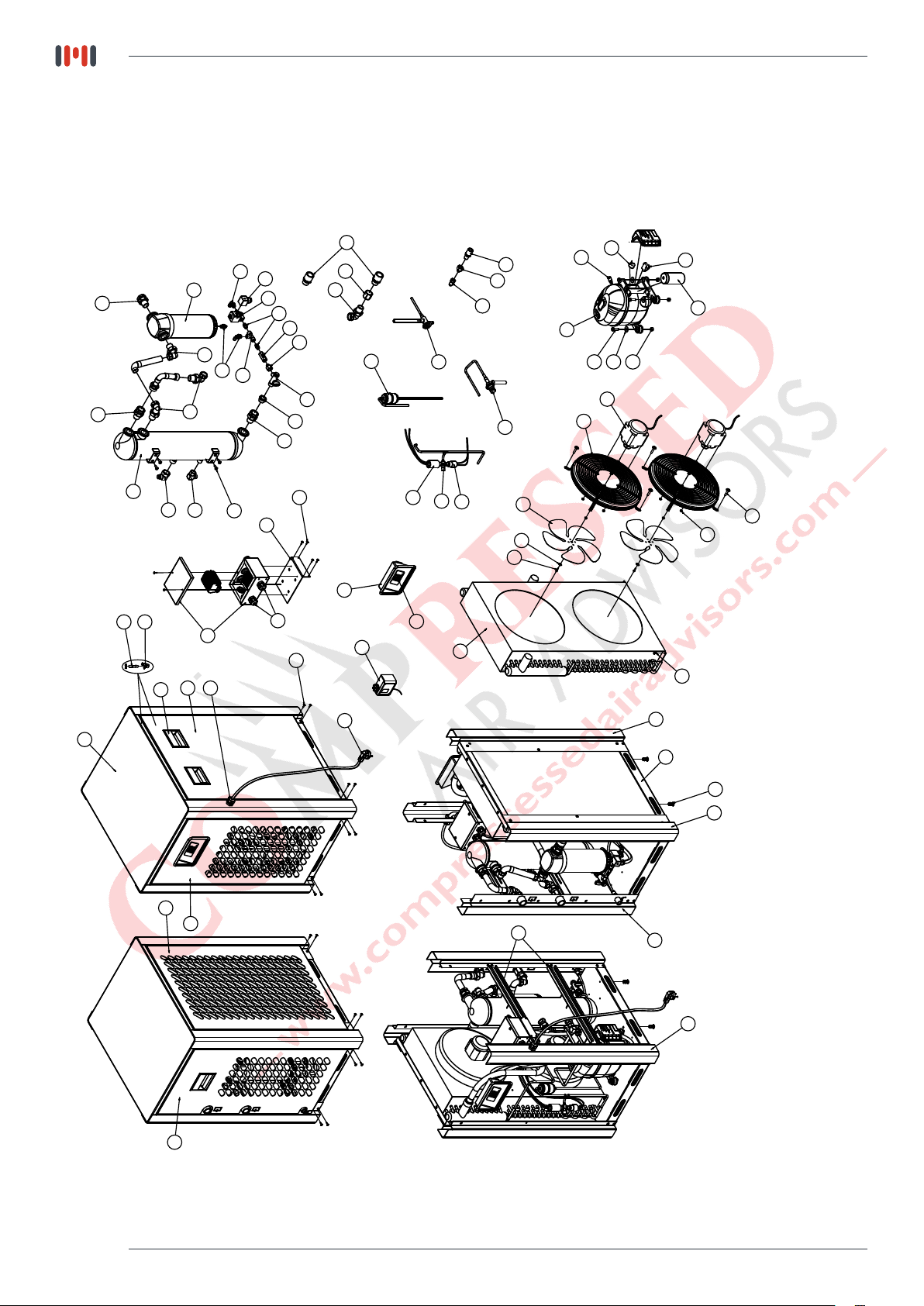
8.1 - ED & Spare Part List
MH-US-15
27
41
26
28
23
44
45
46
61
60
40
38
29
42
59
57
39
37
28
33
26
25
24
30
26
43
38
36
35
34
32
31
49
47
62
21
19
20
14
13
11
48
2
15
12
18
17
16
22
3
9
8
53
5
4
6
7
10
58
54
44
56
55
63
1
50
51
52
Page 36
DECAL CAPACITY
DRYER PART NUMBER POWER RATINGS COOLING FAN MOTOR
8.1 - ED & Spare Part List
MH-US-15
63
POWER CABLE
MK130E-PWC
43
DIGITAL
CONTROLLER
MK130E-DPI
41
M-DCF-0200-WTH
FITTING
DRAIN CONNECTION
36
M-SLV-0325-230
SOLENOID VALVE
27
AIR CONNECTION
FITTING
M-ACF-0050-WTH
15
COMPRESSOR
START RELAY
M-CSR-0035-220-1-50
14
COMPRESSOR
OVERLOAD PROTECTOR
M-COP-0035-220-1-50
12
COMPRESSOR
START CAPACITOR
M-CSC-0035-220-1-50
11
COMPRESSOR
M-CMP-0035-220-1-50
5
MK110E-FMT
AIR COOLED
220V/1Ph/50Hz
.........................
15 SCFM
MH-US-15
N/A
M-PWC-0100
MK130E-DPI
MK130E-DPI-115
M-DCF-0200
M-DCF-0200
M-SLV-0325-230
M-SLV-0150-115
M-ACF-0050
M-ACF-0050
M-CSR-0035-230-1-60
M-CSR-0035-115-1-60
M-COP-0035-230-1-60
M-COP-0035-115-1-60
M-CSC-0035-230-1-60
M-CSC-0035-115-1-60
M-CMP-0035-230-1-60
M-CMP-0035-115-1-60
M-FMT-0200
M-FMT-0150-115-1-60
AIR COOLED
AIR COOLED
230V/1Ph/60Hz
115V/1Ph/60Hz
.........................
.........................
15 SCFM
15 SCFM
MH-US-15
MH-US-15
DWG
SIZE
63
SEE.REF TABLE
62
MK90E-BLT412
61
M-FAS-6000
60
M-STU-6000
59
M-CHN-6000
58
MRH50-CTO
57
MRH50-CLE
56
MRH50-CRI
55
MRH50-CFR
54
MRH50-CRE
53
MRH50-CST
52
MRH050-LEG3
51
MRH050-LEG2
50
MRH050-LEG1
49
MRH50-TSS THERMOSTATIC SUPPORT SHEET
48
M-EXV-0075
47
M-THS-3000
46
MRH75-ECB
45
MK260E-CP11
44
MK260E-CG11
43
SEE.REF TABLE
42
MK260E-PCP
41
SEE.REF TABLE
40
MRH100-FTT
39
MRH100-RDC-1/2-1/4
38
MK170E-EWF
37
MK260E-SVC
36
SEE.REF TABLE
35
MK150E-FIT6 1 / 4" - 6mm FITTINGS
34
MK170E-T1/4 1 / 4" T CONNECTOR
33
MK170E-NIP1/4
32
MK170E-CHV
31
MK150E-RDC
30
M-DBV-0200
29
MRH-WSP-0100
28
MRH35-RKR*90
27
SEE.REF TABLE
26
MRH35-RKR
25
MRH50-MAS-1/2-50
24
MRH35-MAS-1/2-20
23
MRH35-EXC
22
M-DRI-0200
21
MK90E-TDP
20
M-HPS-0200
19
M-FNS-0200
18
MRH100-NT8
17
MK260E-WHR22
16
MK150E-BLT840
15
SEE.REF TABLE
14
SEE.REF TABLE
13
MK260E-STC SETTING THE CONNECTION
12
SEE.REF TABLE COMPRESSOR START CAPACITOR
11
SEE.REF TABLE COMPRESSOR
10
MK90E-BLT412 BOLT M4x12
9
MK110E-WHR20 WASHER Ø20xØ4,3x1,5
8
MK110E-BLT414 BOLT M4x14mm
7
MK110E-NT4 NUT M4
6
MK260E-BLT630 BOLT M6x30
5
SEE.REF TABLE FAN MOTOR
4
M-GRL-0150 FAN GRILL
3
M-FAN-0150 FAN BLADE
2
M-CON-0050-H
1
MRH50-CAD
ITEM
NO
PART NO
POWER CABLE
BOLT M4x12
CABINET FASTENER
CABINET STUD AND NUT
CABINET HANDLE (NEW)
CABINET TOP
CABINET SIDE-LEFT
CABINET SIDE-RIGHT
CABINET FRONT
CABINET REAR
CABINET SUPPORT SHEET
CABINET LEG3
CABINET LEG2
CABINET LEG1
EXPANSION VALVE
THERMOSTATIC SWITCH
ELECTICAL BOX
CABLE PLUG PG11
CABLE GLAND PG11
DIGITAL CONTROLLER
PLASTIC CONTROL PANEL
DRAIN CONNECTION FITTING
1/4 - 8mm FITTING
REDUCTION 1/2 - 1/4
ELBOW FITTINGS
SOLENOID VALVE COIL 1
SOLENOID VALVE
1 / 4" NIPPLE
CHECH VALVE
REDUCTION 3/8 - 1/4
DRAIN BALL VALVE
WATER SEPARATOR
RECORD *90 1/2
AIR CONNECTION FITTING
RECORD 1/2
MANSON 1/2 - 50mm
MANSON 1/2 - 20mm
HEAT EXCHANGER
DRYER-DEHYDRATOR
ADAPTOR T
HIGH PRESSURE SWITCH
FAN ON/OFF SWITCH
NUT M8
WASHER Ø22xØ8,5x2,5
BOLT M8x40
COMPRESSOR START RELAY
COMPRESSOR OVERLOAD PROTECTOR
CONDANSER
CABINET BASE
DESCRIPTION REV QTY
PART LIST
1
24
15
15
3
1
1
1
1
1
1
1
1
1
1
1
1
1
2
6
1
1
1
1
1
2
1
1
1
2
1
1
1
1
4
2
3
1
1
1
1
1
1
1
4
4
4
1
1
1
1
1
6
2
2
8
8
2
2
2
1
1
Page 37

8.1 - ED & Spare Part List
MH-US-25
27
41
45
46
44
23
60
61
26
28
57
59
42
40
29
24
25
28
26
38
26
43
39
33
30
37
47
62
31
32
34
49
35
36
19
38
20
21
48
11
13
22
15
12
18
17
16
3
9
8
53
5
4
6
7
10
14
2
58
55
56
54
44
63
1
50
51
52
Page 38

DECAL CAPACITY
DRYER PART NUMBER POWER RATINGS COOLING FAN MOTOR
63
43
41
36
27
15
14
12
11
5
8.1 - ED & Spare Part List
MH-US-25
POWER CABLE
MK130E-PWC
N/A
M-PWC-0100
DIGITAL
CONTROLLER
MK130E-DPI
MK130E-DPI
MK130E-DPI-115
M-DCF-0200-WTH
M-DCF-0200
M-DCF-0200
FITTING
DRAIN CONNECTION
M-SLV-0325-230
M-SLV-0325-230
SOLENOID VALVE
AIR CONNECTION
COMPRESSOR
COMPRESSOR
COMPRESSOR
COMPRESSOR
M-SLV-0150-115
FITTING
M-ACF-0050-WTH
M-ACF-0050
M-ACF-0050
START RELAY
M-CSR-0050-220-1-50
M-CSR-0050-230-1-60
M-CSR-0050-115-1-60
OVERLOAD PROTECTOR
M-COP-0050-220-1-50
M-COP-0050-230-1-60
M-COP-0050-115-1-60
START CAPACITOR
M-CSC-0050-220-1-50
M-CSC-0050-230-1-60
M-CSC-0050-115-1-60
M-CMP-0050-220-1-50
M-CMP-0050-230-1-60
M-CMP-0050-115-1-60
MK110E-FMT
M-FMT-0200
M-FMT-0150-115-1-60
AIR COOLED
AIR COOLED
AIR COOLED
220V/1Ph/50Hz
230V/1Ph/60Hz
115V/1Ph/60Hz
.........................
.........................
.........................
25 SCFM
25 SCFM
25 SCFM
MH-US-25
MH-US-25
MH-US-25
DWG
SIZE
63
SEE.REF TABLE
62
MK90E-BLT412
61
M-FAS-6000
60
M-STU-6000
59
M-CHN-6000
58
MRH50-CTO
57
MRH50-CLE
56
MRH50-CRI
55
MRH50-CFR
54
MRH50-CRE
53
MRH50-CST
52
MRH050-LEG3
51
MRH050-LEG2
50
MRH050-LEG1
49
MRH50-TSS THERMOSTATIC SUPPORT SHEET
48
M-EXV-0075
47
M-THS-3000
46
MRH75-ECB
45
MK260E-CP11
44
MK260E-CG11
43
SEE.REF TABLE
42
MK260E-PCP
41
SEE.REF TABLE
40
MRH100-FTT
39
MRH100-RDC-1/2-1/4
38
MK170E-EWF
37
MK260E-SVC
36
SEE.REF TABLE
35
MK150E-FIT6 1 / 4" - 6mm FITTINGS
34
MK170E-T1/4 1 / 4" T CONNECTOR
33
MK170E-NIP1/4
32
MK170E-CHV
31
MK150E-RDC
30
M-DBV-0200
29
MRH-WSP-0100
28
MRH35-RKR*90
27
SEE.REF TABLE
26
MRH35-RKR
25
MRH50-MAS-1/2-50
24
MRH35-MAS-1/2-20
23
MRH35-EXC
22
M-DRI-0200
21
MK90E-TDP
20
M-HPS-0200
19
M-FNS-0200
18
MRH100-NT8
17
MK260E-WHR22
16
MK150E-BLT840
15
SEE.REF TABLE
14
SEE.REF TABLE
13
MK260E-STC SETTING THE CONNECTION
12
SEE.REF TABLE COMPRESSOR START CAPACITOR
11
SEE.REF TABLE COMPRESSOR
10
MK90E-BLT412 BOLT M4x12
9
MK110E-WHR20 WASHER Ø20xØ4,3x1,5
8
MK110E-BLT414 BOLT M4x14mm
7
MK110E-NT4 NUT M4
6
MK260E-BLT630 BOLT M6x30
5
SEE.REF TABLE FAN MOTOR
4
M-GRL-0150 FAN GRILL
3
M-FAN-0150 FAN BLADE
2
M-CON-0050-H
1
MRH50-CAD
ITEM
NO
PART NO
POWER CABLE
BOLT M4x12
CABINET FASTENER
CABINET STUD AND NUT
CABINET HANDLE (NEW)
CABINET TOP
CABINET SIDE-LEFT
CABINET SIDE-RIGHT
CABINET FRONT
CABINET REAR
CABINET SUPPORT SHEET
CABINET LEG3
CABINET LEG2
CABINET LEG1
EXPANSION VALVE
THERMOSTATIC SWITCH
ELECTICAL BOX
CABLE PLUG PG11
CABLE GLAND PG11
DIGITAL CONTROLLER
PLASTIC CONTROL PANEL
DRAIN CONNECTION FITTING
1/4 - 8mm FITTING
REDUCTION 1/2 - 1/4
ELBOW FITTINGS
SOLENOID VALVE COIL 1
SOLENOID VALVE
1 / 4" NIPPLE
CHECH VALVE
REDUCTION 3/8 - 1/4
DRAIN BALL VALVE
WATER SEPARATOR
RECORD *90 1/2
AIR CONNECTION FITTING
RECORD 1/2
MANSON 1/2 - 50mm
MANSON 1/2 - 20mm
HEAT EXCHANGER
DRYER-DEHYDRATOR
ADAPTOR T
HIGH PRESSURE SWITCH
FAN ON/OFF SWITCH
NUT M8
WASHER Ø22xØ8,5x2,5
BOLT M8x40
COMPRESSOR START RELAY
COMPRESSOR OVERLOAD PROTECTOR
CONDANSER
CABINET BASE
DESCRIPTION REV QTY
PART LIST
1
24
15
15
3
1
1
1
1
1
1
1
1
1
1
1
1
1
2
6
1
1
1
1
1
2
1
1
1
2
1
1
1
1
4
2
3
1
1
1
1
1
1
1
4
4
4
1
1
1
1
1
6
2
2
8
8
2
2
2
1
1
Page 39

8.1 - ED & Spare Part List
MH-US-35
27
41
45
46
44
23
60
61
26
28
57
59
42
40
29
24
25
28
26
38
26
43
39
33
30
37
47
62
31
32
34
49
35
36
19
38
20
21
11
48
13
22
15
12
18
17
16
3
9
8
53
5
4
6
7
10
14
2
58
55
54
56
44
63
1
50
51
52
Page 40
DECAL CAPACITY
DRYER PART NUMBER POWER RATINGS COOLING FAN MOTOR
63
43
41
36
27
15
14
12
11
5
8.1 - ED & Spare Part List
MH-US-35
POWER CABLE
MK130E-PWC
N/A
M-PWC-0100
DIGITAL
CONTROLLER
MK130E-DPI
MK130E-DPI
MK130E-DPI-115
M-DCF-0200-WTH
M-DCF-0200
M-DCF-0200
FITTING
DRAIN CONNECTION
M-SLV-0325-230
M-SLV-0325-230
SOLENOID VALVE
AIR CONNECTION
COMPRESSOR
COMPRESSOR
COMPRESSOR
COMPRESSOR
M-SLV-0150-115
FITTING
M-ACF-0050-WTH
M-ACF-0050
M-ACF-0050
START RELAY
M-CSR-0035-220-1-50
M-CSR-0035-230-1-60
M-CSR-0035-115-1-60
OVERLOAD PROTECTOR
M-COP-0035-220-1-50
M-COP-0035-230-1-60
M-COP-0035-115-1-60
START CAPACITOR
M-CSC-0035-220-1-50
M-CSC-0035-230-1-60
M-CSC-0035-115-1-60
M-CMP-0035-220-1-50
M-CMP-0035-230-1-60
M-CMP-0035-115-1-60
MK110E-FMT
M-FMT-0200
M-FMT-0150-115-1-60
AIR COOLED
AIR COOLED
AIR COOLED
220V/1Ph/50Hz
230V/1Ph/60Hz
115V/1Ph/60Hz
.........................
.........................
.........................
35 SCFM
35 SCFM
35 SCFM
MH-US-35
MH-US-35
MH-US-35
DWG
SIZE
63
SEE.REF TABLE
62
MK90E-BLT412
61
M-FAS-6000
60
M-STU-6000
59
M-CHN-6000
58
MRH50-CTO
57
MRH50-CLE
56
MRH50-CRI
55
MRH50-CFR
54
MRH50-CRE
53
MRH50-CST
52
MRH050-LEG3
51
MRH050-LEG2
50
MRH050-LEG1
49
MRH50-TSS THERMOSTATIC SUPPORT SHEET
48
M-EXV-0075
47
M-THS-3000
46
MRH75-ECB
45
MK260E-CP11
44
MK260E-CG11
43
SEE.REF TABLE
42
MK260E-PCP
41
SEE.REF TABLE
40
MRH100-FTT
39
MRH100-RDC-1/2-1/4
38
MK170E-EWF
37
MK260E-SVC
36
SEE.REF TABLE
35
MK150E-FIT6 1 / 4" - 6mm FITTINGS
34
MK170E-T1/4 1 / 4" T CONNECTOR
33
MK170E-NIP1/4
32
MK170E-CHV
31
MK150E-RDC
30
M-DBV-0200
29
MRH-WSP-0100
28
MRH35-RKR*90
27
SEE.REF TABLE
26
MRH35-RKR
25
MRH50-MAS-1/2-50
24
MRH35-MAS-1/2-20
23
MRH35-EXC
22
M-DRI-0200
21
MK90E-TDP
20
M-HPS-0200
19
M-FNS-0200
18
MRH100-NT8
17
MK260E-WHR22
16
MK150E-BLT840
15
SEE.REF TABLE
14
SEE.REF TABLE
13
MK260E-STC SETTING THE CONNECTION
12
SEE.REF TABLE COMPRESSOR START CAPACITOR
11
SEE.REF TABLE COMPRESSOR
10
MK90E-BLT412 BOLT M4x12
9
MK110E-WHR20 WASHER Ø20xØ4,3x1,5
8
MK110E-BLT414 BOLT M4x14mm
7
MK110E-NT4 NUT M4
6
MK260E-BLT630 BOLT M6x30
5
SEE.REF TABLE FAN MOTOR
4
M-GRL-0150 FAN GRILL
3
M-FAN-0150 FAN BLADE
2
M-CON-0050-H
1
MRH50-CAD
ITEM
NO
PART NO
POWER CABLE
BOLT M4x12
CABINET FASTENER
CABINET STUD AND NUT
CABINET HANDLE (NEW)
CABINET TOP
CABINET SIDE-LEFT
CABINET SIDE-RIGHT
CABINET FRONT
CABINET REAR
CABINET SUPPORT SHEET
CABINET LEG3
CABINET LEG2
CABINET LEG1
EXPANSION VALVE
THERMOSTATIC SWITCH
ELECTICAL BOX
CABLE PLUG PG11
CABLE GLAND PG11
DIGITAL CONTROLLER
PLASTIC CONTROL PANEL
DRAIN CONNECTION FITTING
1/4 - 8mm FITTING
REDUCTION 1/2 - 1/4
ELBOW FITTINGS
SOLENOID VALVE COIL 1
SOLENOID VALVE
1 / 4" NIPPLE
CHECH VALVE
REDUCTION 3/8 - 1/4
DRAIN BALL VALVE
WATER SEPARATOR
RECORD *90 1/2
AIR CONNECTION FITTING
RECORD 1/2
MANSON 1/2 - 50mm
MANSON 1/2 - 20mm
HEAT EXCHANGER
DRYER-DEHYDRATOR
ADAPTOR T
HIGH PRESSURE SWITCH
FAN ON/OFF SWITCH
NUT M8
WASHER Ø22xØ8,5x2,5
BOLT M8x40
COMPRESSOR START RELAY
COMPRESSOR OVERLOAD PROTECTOR
CONDANSER
CABINET BASE
DESCRIPTION REV QTY
PART LIST
1
24
15
15
3
1
1
1
1
1
1
1
1
1
1
1
1
1
2
6
1
1
1
1
1
2
1
1
1
2
1
1
1
1
4
2
3
1
1
1
1
1
1
1
4
4
4
1
1
1
1
1
6
2
2
8
8
2
2
2
1
1
Page 41

8.1 - ED & Spare Part List
MH-US-50
35
25
51
24
24
24
67
27
23
44
63
50
24
37
36
45
64
62
34
33
30
29
28
32
31
26
25
49
43
47
57
38
14
61
39
40
27
19
65
24
20
21
48
69
46
41
22
3
9
8
2
13
11
161718
5
4
42
15
12
6
7
10
53
1
Page 42
52
58
43
60
68
59
66
56
54
55

DECAL CAPACITY
DRYER PART NUMBER POWER RATINGS COOLING FAN MOTOR
66
POWER CABLE
MK130E-PWC
N/A
61
M-DCF-0200-WTH
M-DCF-0200
FITTING
DRAIN CONNECTION
48
DIGITAL
CONTROLLER
MK130E-DPI
MK130E-DPI
38
AIR CONNECTION
FITTING
M-ACF-0050-WTH
M-ACF-0050
33
M-SLV-0325-230
M-SLV-0325-230
SOLENOID VALVE
15
COMPRESSOR
START RELAY
M-CSR-0075-220-1-50
M-CSR-0075-230-1-60
14
COMPRESSOR
OVERLOAD PROTECTOR
M-COP-0075-220-1-50
M-COP-0075-230-1-60
12
COMPRESSOR
START CAPACITOR
M-CSC-0075-220-1-50
M-CSC-0075-230-1-60
11
COMPRESSOR
M-CMP-0075-220-1-50
M-CMP-0075-230-1-60
5
MK110E-FMT
M-FMT-0200
AIR COOLED
AIR COOLED
220V/1Ph/50Hz
230V/1Ph/60Hz
.........................
.........................
50 SCFM
50 SCFM
8.1 - ED & Spare Part List
MH-US-50
MH-US-50
MH-US-50
M-PWC-0100
M-DCF-0200
MK130E-DPI-115
M-ACF-0050
M-SLV-0150-115
M-CSR-0075-115-1-60
M-COP-0075-115-1-60
M-CSC-0075-115-1-60
M-CMP-0075-115-1-60
M-FMT-0150-115-1-60
AIR COOLED
115V/1Ph/60Hz
.........................
50 SCFM
MH-US-50
DWG
SIZE
69
MRH50-TSS
68
MRH50-CTO CABINET TOP
67
MRH50-MAS-1/2
66
SEE.REF TABLE POWER CABLE
65
MK90E-BLT412 BOLT M4x12
64
M-FAS-6000 CABINET FASTENER
63
M-STU-6000
62
M-CHN-6000
61
SEE.REF TABLE
60
MRH50-CRI
59
MRH50-CFR
58
MRH50-CRE
57
MRH50-CLE
56
MRH50-EXCD
55
MRH050-LEG4
54
MRH050-LEG3
53
MRH050-LEG2
52
MRH050-LEG1
51
MRH-WSP-0100
50
MK150E-FIT6
49
MK90E-BLT615
48
SEE.REF TABLE
47
MK260E-PCP
46
M-THS-3000
45
MRH75-ECB
44
MK260E-CP11
43
MK260E-CG11
42
MRH50-CST
41
M-EXV-0075
40
MRH100-MAS-3/4
39
MRH100-FTT
38
SEE.REF TABLE
37
MK110E-RTA2
36
MK70E-RTA3
35
MK170E-EWF
34
MK260E-SVC SOLENOID VALVE COIL
33
SEE.REF TABLE SOLENOID VALVE
32
MK170E-EWF
31
MK170E-T1/4
30
MK170E-NIP1/4 1 / 4" NIPPLE
29
MK170E-CHV
28
MK150E-RDC
27
M-DBV-0200
26
MRH100-RDC
25
MRH100-RKR
24
MRH100-RKR*90
23
MRH100-EXC
22
M-DRI-0200
21
MK90E-TDP
20
M-HPS-0200
19
M-FNS-0200
18
MRH100-NT8
17
MK260E-WHR22
16
MK150E-BLT840
15
SEE.REF TABLE
14
SEE.REF TABLE
13
MK260E-STC SETTING THE CONNECTION
12
SEE.REF TABLE COMPRESSOR START CAPACITOR
11
SEE.REF TABLE COMPRESSOR
10
MK90E-BLT412 BOLT M4x12
9
MK110E-WHR20 WASHER Ø20xØ4,3x1,5
8
MK110E-BLT414 BOLT M4x14mm
7
MK110E-NT4 NUT M4
6
MK260E-BLT630 BOLT M6x30
5
SEE.REF TABLE FAN MOTOR
4
M-GRL-0150 FAN GRILL
3
M-FAN-0150 FAN BLADE
2
M-CON-0050-H
1
MRH50-CAD
ITEM
NO
PART NO
THERMOSTATIC
MANSON 1/2
CABINET STUD AND NUT
CABINET HANDLE (NEW)
DRAIN CONNECTION FITTING
CABINET SIDE-RIGHT
CABINET FRONT
CABINET REAR
CABINET SIDE-LEFT
HEAT EXCHANGER SUPPORT SHEET
CABINET LEG4
CABINET LEG3
CABINET LEG2
CABINET LEG1
WATER SEPARATOR
1 / 4" - 6mm FITTINGS
BOLT M6x15
DIGITAL CONTROLLER 1
PLASTIC CONTROL PANEL
THERMOSTATIC SWITCH
ELECTICAL BOX
CABLE PLUG PG11
CABLE GLAND PG11
CABINET SUPPORT SHEET
EXPANSION VALVE
MANSON 3/4
1/4 - 8mm FITTING
AIR CONNECTION FITTING
ROTOLOCK ADAPTOR2
ROTOLOCK ADAPTOR3
ELBOW FITTINGS
90* 1 / 4" - 6mm ELBOW
1 / 4" T CONNECTOR
CHECH VALVE
REDUCTION 3/8 - 1/4
DRAIN BALL VALVE
REDUCTION 3/4 - 1/2
RECORD 3/4
RECORD *90 3/4
HEAT EXCHANGER
DRYER-DEHYDRATOR
ADAPTOR T
HIGH PRESSURE SWITCH
FAN ON/OFF SWITCH
NUT M8
WASHER Ø22xØ8,5x2,5
BOLT M8x40
COMPRESSOR START RELAY
COMPRESSOR OVERLOAD PROTECTOR
CONDANSER
CABINET BASE
DESCRIPTION REV QTY
PART LIST
SUPPORT SHEET
1
1
1
1
24
15
15
3
1
1
1
1
1
2
1
1
1
1
1
1
4
1
1
1
2
6
1
1
2
1
2
1
1
1
1
1
2
1
2
1
1
1
2
2
6
1
1
1
1
1
4
4
4
1
1
1
1
1
6
2
2
8
8
2
2
2
1
1
Page 43
8.1 - ED & Spare Part List
MH-US-75
38
35
25
25
23
63
64
14
24
24
67
36
43
37
58
59
34
33
30
29
32
31
26
25
49
42
37
62
40
24
28
22
27
62
47
46
41
19
21
48
61
28
39
18
20
2
3
9
8
11
13
151617
4
44
5
45
12
6
7
10
66
60
56
57
55
54
51
1
65
50
52
53
Page 44

DECAL CAPACITY
DRYER PART NUMBER POWER RATINGS COOLING FAN MOTOR
8.1 - ED & Spare Part List
MH-US-75
66
POWER CABLE
MK130E-PWC
61
M-DCF-0200-WTH
FITTING
DRAIN CONNECTION
48
DIGITAL
CONTROLLER
MK130E-DPI
45
COMPRESSOR
START RELAY
M-CSR-0075-220-1-50
44
M-COP-0075-220-1-50
COMPRESSOR
OVERLOAD PROTECTOR
38
AIR CONNECTION
FITTING
M-ACF-0100-WTH
33
M-SLV-0325-230
SOLENOID VALVE
12
COMPRESSOR
START CAPACITOR
M-CSC-0100-220-1-50
11
COMPRESSOR
M-CMP-0100-220-1-50
5
MK110E-FMT
AIR COOLED
220V/1Ph/50Hz
.........................
100 SCFM
MH-US-75
N/A
M-PWC-0100
M-DCF-0200
M-DCF-0200
MK130E-DPI
MK130E-DPI-115
M-CSR-0075-230-1-60
M-CSR-0075-115-1-60
M-COP-0075-230-1-60
M-COP-0075-115-1-60
M-ACF-0100
M-ACF-0100
M-SLV-0325-230
M-SLV-0150-115
M-CSC-0075-230-1-60
M-CSC-0075-115-1-60
M-CMP-0075-230-1-60
M-CMP-0075-115-1-60
M-FMT-0200
M-FMT-0150-115-1-60
AIR COOLED
AIR COOLED
230V/1Ph/60Hz
115V/1Ph/60Hz
.........................
.........................
100 SCFM
100 SCFM
MH-US-75
MH-US-75
DWG
SIZE
67
MK110E-RTA2 ROTOLOCK ADAPTOR2
66
SEE.REF TABLE POWER CABLE
65
MK260E-RNT8 RIVET NUT M8
64
M-FAS-6000 CABINET FASTENER
63
M-STU-6000
62
MK90E-BLT412
61
SEE.REF TABLE
60
MRH100-CTO
59
M-CHN-6000
58
MRH100-CRI
57
MRH100-CFR
56
MRH100-CLE
55
MRH100-CRE
54
MRH100-EXCD
53
MRH100-LEG4
52
MRH100-LEG3
51
MRH100-LEG2
50
MRH100-LEG1
49
MK90E-BLT615
48
SEE.REF TABLE
47
MK260E-PCP
46
M-THS-3000
45
SEE.REF TABLE
44
SEE.REF TABLE
43
MRH75-ECB
42
MRH75-SSH
41
M-EXV-0075
40
MRH100-MAS-3/4
39
MRH100-FTT
38
SEE.REF TABLE
37
MK260E-CG11 CABLE GLAND PG11
36
MK70E-RTA3
35
MK170E-EWF
34
MK260E-SVC SOLENOID VALVE COIL
33
SEE.REF TABLE SOLENOID VALVE
32
MK170E-EWF
31
MK170E-T1/4
30
MK170E-NIP1/4 1 / 4" NIPPLE
29
MK170E-CHV
28
MK150E-RDC
27
M-DBV-0200
26
MRH100-RDC
25
MRH100-RKR
24
MRH100-RKR*90
23
MRH100-EXC
22
M-DRI-0200
21
MK90E-TDP
20
M-HPS-0200
19
M-FNS-0200
18
M-BYV-0100
17
MRH100-NT8
16
MK260E-WHR22
15
MK150E-BLT840
14
MRH-WSP-0100
13
MK260E-STC SETTING THE CONNECTION
12
SEE.REF TABLE COMPRESSOR START CAPACITOR
11
SEE.REF TABLE COMPRESSOR
10
MK90E-BLT412 BOLT M4x12
9
MK110E-WHR20 WASHER Ø20xØ4,3x1,5
8
MK110E-BLT414 BOLT M4x14mm
7
MK110E-NT4 NUT M4
6
MK260E-BLT630 BOLT M6x30
5
SEE.REF TABLE FAN MOTOR
4
M-GRL-0200 FAN GRILL
3
M-FAN-0200 FAN BLADE
2
M-CON-0100-H
1
MRH100-CAD
ITEM
NO
PART NO
CABINET STUD AND NUT
BOLT M4x12
DRAIN CONNECTION FITTING
CABINET TOP
CABINET HANDLE (NEW)
CABINET SIDE-RIGHT
CABINET FRONT
CABINET SIDE-LEFT
CABINET REAR
HEAT EXCHANGER SUPPORT SHEET
CABINET LEG4
CABINET LEG3
CABINET LEG2
CABINET LEG1
BOLT M6x15
DIGITAL CONTROLLER 1
PLASTIC CONTROL PANEL
THERMOSTATIC SWITCH
COMPRESSOR START RELAY
COMPRESSOR OVERLOAD PROTECTOR
ELECTICAL BOX
SUPPORT SHEET
EXPANSION VALVE
MANSON 3/4
1/4 - 8mm FITTING
AIR CONNECTION FITTING
ROTOLOCK ADAPTOR2
ELBOW FITTINGS
90* 1 / 4" - 6mm ELBOW
1 / 4" T CONNECTOR
CHECH VALVE
REDUCTION 3/8 - 1/4
DRAIN BALL VALVE
REDUCTION 3/4 - 1/2
RECORD 3/4
RECORD *90 3/4
HEAT EXCHANGER
DRYER-DEHYDRATOR
ADAPTOR T
HIGH PRESSURE SWITCH
FAN ON/OFF SWITCH
BY-PASS VALVE
NUT M8
WASHER Ø22xØ8,5x2,5
BOLT M8x40
WATER SEPARATOR
CONDANSER
CABINET BASE
DESCRIPTION REV QTY
PART LIST
1
1
4
15
15
16
1
1
3
1
1
1
1
2
1
1
1
1
4
1
1
1
1
1
1
1
1
1
2
3
1
1
1
1
2
1
2
1
1
1
1
3
4
1
1
1
1
1
1
4
4
4
1
1
1
1
6
2
2
8
8
2
2
2
1
1
Page 45

8.1 - ED & Spare Part List
MH-US-100
38
35
25
25
23
63
64
67
24
24
36
14
42
43
34
33
30
29
32
31
25
49
44
40
24
28
22
27
26
47
45
46
62
41
19
21
48
2
61
28
14
39
12
11
13
4
18
3
20
9
8
16
17
15
5
6
7
10
59
60
56
57
66
54
51
1
65
50
52
53
37
58
Page 46
55

DECAL
DRYER PART NUMBER POWER RATINGS COOLING FAN MOTOR
8.1 - ED & Spare Part List
MH-US-100
66
POWER CABLE
MK130E-PWC
61
M-DCF-0200-WTH
FITTING
DRAIN CONNECTION
48
DIGITAL
CONTROLLER
MK130E-DPI
45
COMPRESSOR
START CAPACITOR
M-CSC-0100-220-1-50
44
START RELAY
COMPRESSOR
M-CSR-0100-220-1-50
42
COMPRESSOR
ELECTRICAL BOX
M-CEB-0100-220-1-50
38
AIR CONNECTION
FITTING
M-ACF-0100-WTH
33
M-SLV-0325-230
SOLENOID VALVE
12
COMPRESSOR
M-COP-0100-220-1-50
OVERLOAD PROTECTOR
11
COMPRESSOR
M-CMP-0100-220-1-50
5
MK110E-FMT
AIR COOLED
220V/1Ph/50Hz
.........................
CAPACITY
100 SCFM
MH-US-100
N/A
M-PWC-0100
M-DCF-0200
M-DCF-0200
MK130E-DPI
MK130E-DPI-115
M-CSC-0100-230-1-60
M-CSC-0100-115-1-60
M-CSR-0100-230-1-60
M-CSR-0100-115-1-60
M-CEB-0100-230-1-60
M-CEB-0100-115-1-60
M-ACF-0100
M-ACF-0100
M-SLV-0325-230
M-SLV-0150-115
M-COP-0100-230-1-60
M-COP-0100-115-1-60
M-CMP-0100-230-1-60
M-CMP-0100-115-1-60
M-FMT-0200
M-FMT-0150-115-1-60
AIR COOLED
AIR COOLED
230V/1Ph/60Hz
115V/1Ph/60Hz
.........................
.........................
100 SCFM
100 SCFM
MH-US-100
MH-US-100
DWG
SIZE
67
MRH-WSP-0100 WATER SEPARATOR
66
SEE.REF TABLE POWER CABLE
65
MK260E-RNT8 RIVET NUT M8
64
M-FAS-6000 CABINET FASTENER
63
M-STU-6000
62
MK90E-BLT412
61
SEE.REF TABLE
60
MRH100-CTO
59
M-CHN-6000
58
MRH100-CRI
57
MRH100-CFR
56
MRH100-CLE
55
MRH100-CRE
54
MRH100-EXCD
53
MRH100-LEG4
52
MRH100-LEG3
51
MRH100-LEG2
50
MRH100-LEG1
49
MK90E-BLT615
48
SEE.REF TABLE
47
MK260E-PCP
46
M-THS-3000
45
SEE.REF TABLE
44
SEE.REF TABLE
43
MK110E-TRM
42
SEE.REF TABLE
41
M-EXV-0200
40
MRH100-MAS-3/4
39
MRH100-FTT
38
SEE.REF TABLE
37
MK260E-CG11 CABLE GLAND PG11
36
MK70E-RTA3
35
MK170E-EWF
34
MK260E-SVC SOLENOID VALVE COIL
33
SEE.REF TABLE SOLENOID VALVE
32
MK170E-EWF
31
MK170E-T1/4
30
MK170E-NIP1/4 1 / 4" NIPPLE
29
MK170E-CHV
28
MK150E-RDC
27
M-DBV-0200
26
MRH100-RDC
25
MRH100-RKR
24
MRH100-RKR*90
23
MRH100-EXC
22
M-DRI-0200
21
MK90E-TDP
20
M-HPS-0200
19
M-FNS-0200
18
M-BYV-0100
17
MRH100-NT8
16
MK260E-WHR22
15
MK150E-BLT840
14
MK110E-RTA2
13
MK260E-STC SETTING THE CONNECTION
12
SEE.REF TABLE COMPRESSOR OVERLOAD PROTECTOR
11
SEE.REF TABLE COMPRESSOR
10
MK90E-BLT412 BOLT M4x12
9
MK110E-WHR20 WASHER Ø20xØ4,3x1,5
8
MK110E-BLT414 BOLT M4x14mm
7
MK110E-NT4 NUT M4
6
MK260E-BLT630 BOLT M6x30
5
SEE.REF TABLE FAN MOTOR
4
M-GRL-0200 FAN GRILL
3
M-FAN-0200 FAN BLADE
2
M-CON-0100-H
1
MRH100-CAD
ITEM
NO
PART NO
CABINET STUD AND NUT
BOLT M4x12
DRAIN CONNECTION FITTING
CABINET TOP
CABINET HANDLE (NEW)
CABINET SIDE-RIGHT
CABINET FRONT
CABINET SIDE-LEFT
CABINET REAR
HEAT EXCHANGER SUPPORT SHEET
CABINET LEG4
CABINET LEG3
CABINET LEG2
CABINET LEG1
BOLT M6x15
DIGITAL CONTROLLER 1
PLASTIC CONTROL PANEL
THERMOSTATIC SWITCH
COMPRESSOR START CAPACITOR
COMPRESSOR START RELAY
THERMINAL BLOCK
COMPRESSOR ELECTRICAL BOX
EXPANSION VALVE
MANSON 3/4
1/4 - 8mm FITTING
AIR CONNECTION FITTING
ROTOLOCK ADAPTOR2
ELBOW FITTINGS
90* 1 / 4" - 6mm ELBOW
1 / 4" T CONNECTOR
CHECH VALVE
REDUCTION 3/8 - 1/4
DRAIN BALL VALVE
REDUCTION 3/4 - 1/2
RECORD 3/4
RECORD *90 3/4
HEAT EXCHANGER
DRYER-DEHYDRATOR
ADAPTOR T
HIGH PRESSURE SWITCH
FAN ON/OFF SWITCH
BY-PASS VALVE
NUT M8
WASHER Ø22xØ8,5x2,5
BOLT M8x40
ROTOLOCK ADAPTOR2
CONDANSER
CABINET BASE
DESCRIPTION REV QTY
PART LIST
1
1
4
15
15
16
1
1
3
1
1
1
1
2
1
1
1
1
4
1
1
1
1
1
1
1
1
1
2
1
1
1
1
1
2
1
2
1
1
1
1
3
4
1
1
1
1
1
1
4
4
4
1
1
1
1
6
2
2
8
8
2
2
2
1
1
Page 47

9. COMPONENTS LOCATION
All main components located into dryer identified with labels as listed here under.
CAUTION: Due to manufacture design, some components out of the list are not installed into the dryer.
Electrical components:
Accessories :
A01: Control circuit transformer
A02: Power circuit transformer
A10: ON warning light
A11: OFF warning light
A20: Drain solenoid valve
A30: Cranckase heater
A31: Electrical resistor
A40: Electrical capacity
EV3 Digital Controller (Digi-Pro)
A50-3: Energy saving device 3 (ESD3)
Relays :
K01: Compressor motor relay
K10: Fan motor relay
K20: Drain timer or Bekomat (optional)
K30: Temperature Controller
Switches :
S01: Main switch
S02: Start push button
S03: Stop push button
S10: Fan pressure control
S11: High-low pressure security control
S12: High pressure security control
S13: Low pressure security control
S20: Refrigerant temperature control
S21: Air temperature control
Motors :
M01: Refrigerant compressor motor
M10: Fan motor
Thermal protections :
P01: Refrigerant compressor thermal overload
P10: Fan motor thermal overload
Fuses protections :
See complete identification into electrical sketch included in dryer
F--: Transformer protection
F--: Fan protection
F--: Compressor relay protection
F--: Transformer protection
F--: Drain protection
F--: Fan relay protection
Refrigerant components:
G01: Liquid receiver
G02: Refrigerant drier
G03: Expansion valve
G04: Liquid separator
G05: Hot gas bypass valve
G06: Refrigerant solenoid valve
G10: Water cooled condenser
G11: Water control valve
G20: Refrigerant evaporating pressure gauge
G21: Refrigerant evaporating temperature gauge
Compressed air components :
H01: Air inlet prefilter
H11: Drain filter
H12: Pneumatic drain valve
Terminal boxes:
B01: Main terminal box
B11: Refrigeranbt unit termal box
B12: Free of potential terminal box
Page 48
Problem Possible Cause Repair Comments
Dryer is
switched on,
indicator light
is lit but the
refrigerant
compressor
does not turn on.
Dryer is
switched on,
but the refrigerant
compressor
does not turn on.
Dryer is switched
on but fan is not
running.
The connection has
inverted phases
Refrigeration unit is not
functioning
The refrigerant highpressure
protection has tripped
Excessive ambient temperature
Excessive temperature on
crankcase of compressor.
Excessive compressed
air inlet temperature.
Clogged condenser fins or
clogged water condenser.
Possible high crankcase
temperature
Possible loss of phase
Possible low voltage causing
overload trip Possible failed
compressor
Too much compressed air
flow.
Faulty electrical wiring Inspect the circuit The compressor-on light should be wired into the
One electrical protection
has tripped.
Fan has to run if refrigerant
high
pressure reaches upper set
point.
Invert two phases 3-phase dryers are equipped with a phase controller
Check refrigeration compressor
The refrigerant safety high
pressure switch has tripped.
In case of water cooled condensers, check the water
control valve
Be sure that dryer is working
in temperatures lower than
the
design conditions.
Designed conditions and
correction factors are described
in this manual.
Allow time to compressor to
cool down. Reason may be a
possible incorrect adjustment
of hot gas bypass valve or
shortage of refrigerant
Be sure that dryer is working
in temperatures lower than
design conditions.
Clear fins or water condenser
of all obstructions.
Check actual flow
through the dryer.
Reset the protection or
replace the blown fuse.
Check that compressed air
flows through the dryer.
Check
that fan blades are free to
move.
Check the fan pressure
switch.
to avoid the fans from turning in the opposite
direction.
Several factors can cause compressor failure.
A qualified refrigeration technician needs to check
all the electrical and refrigerant circuit and controls.
The dryer is protected against excessively high
refrigerant pressure. If the condenser eciency has
reduced, the switch will trip. Manually reset the
switch.
A high ambient temperature may cause the
refrigerant system to operate at higher than normal
pressures. Results will be higher than normal
evaporator temperature.
lmportant: adequate air circulation around the dryer,
and proper ventilation in the equipment room should
guarantee a low enough ambient temperature.
Compressor is protected against overly high
temperatures of the crankcase by a thermal switch.
The dryer is designed for working in calculated
conditions (see description in this manual).
If conditions are exceeded, the dryer will be
overflowed, dew point will go up and protecting
devices can switch o.
The clogged fins in the condenser will restrict the
air passage and reduce the refrigeration capacity,
causing high temperature in the evaporator.
Same will occur if water condenser is clogged with
mud or dirt. Air condenser and water condenser
should be periodically checked and cleaned.
Protect water circuit by an adapted filter.
This dryer is designed for a maximum air flow at
design conditions. If too much air is pumped
into the dryer, water removal capacity may not be
sucient, resulting in liquid carryover down stream.
Check the rated output the air compressor.
refrigerant compressor circuit. See wiring diagrams
in this manual.
The dryer is protected against high amp draw by
fuse and/or overload relay that can trip in case of
need. Reset or replace fuse once, but do not persist
if it trips again, request assistance from a qualified
refrigeration contractor.
Fan operates automatically to keep refrigerant
pressure below the maximum value. The fan can
stop if pressure is under the recommended setting.
When compressor
starts, it vibrates
a lot and makes
mechanical noise.
Compressor is slugging
liquid refrigerant
at start up.
Be sure the pre-heating
period
of at least 2 hours is
respected
Refrigerant may move between receivers when
refrigerant compressor is stopped and not heated,
especially if stopped for a long time.
This migration may cause liquid shock (slugging) in
valves specially on large dryers containing more
refrigerant
Page 49

Problem Possible Cause Repair Comments
Water in system Compressed Air Inlet and
High
pressure
drop
The unit will not
run or cycles o
and on.
outlet connections are
reversed.
Drain system is clogged
or inoperative.
Bypass system is open Check the valves Important: Bypass piping should be installed around the
Free moisture remains in pipe
lines.
Excessive air flow Check actual flow
Excessive free moisture Check the separator and
Excessive compressed
air inlet temperature.
Clogged condenser fins Clear fins of all obstru-
Shortage of refrigerant Fix the leak and add a
Refrigeration system is
not functioning
Excessive pressure dew point Readjust refrigerant
Excessive compressed
air flow or too law air inlet
pressure.
Freeze up Check that compressor
Clogged heat exchanger Clean heat exchanger
Line disconnect switch is
open.
Fuse or breaker is open Replace fuse or reset
Faulty refrigerant
compressor or controls.
Excessive compressed air
inlet temperature.
Check inlet and outlet
connections.
Restore a free flow of
water condensate. Check
water evacuation.
Blow out the system Before the dryer is first started all free moisture should be
through the dryer.
drain system and
compressor after cooler
ahead of the dryer.
Be sure that dryer is working lower than design
conditions
ctions
charge of refrigerant.
Check to be certain
refrigerant
compressor is running
evaporating pressure
Check actual pressure and
flow through the dryer.
room
ambient,
Fan switch could have
failed in closed position
keeping fan on.
with areverse air flow.
Close the start or
disconnect switch.
breaker.
Determine the cause and
make
correction
Design conditions and
correction
factors are described in
this manual.
Be sure that dryer is
working
in ambient temperatures
below design conditions.
This dryer is designed for air flow in one direction only. Inlet and
outlet directions are identified on the dryer.
Drain system is timed solenoid valve, pneumatically assisted which
has to be adjusted in accordance with values listed in this
manual. The Solenoid valve includes a strainer that has to be
periodically checked and cleaned. Membranes of pneumatically
assisted drain have to be checked or replaced every 6 months.
dryer so the dryer can be isolated for service without
shutting down the air supply. During dryer operation, valves
must be set so all air goes into the system. Check tightness of the
bypass system.
blown out of the system.
This dryer is designed for a maximum air flow. If too much air is
pumped into the dryer, water removal capacity may not be
sucient, resultingin liquid Carry over downstream. Check the
rated flow of the air compressor .
In some system there may be an accumulation of free moisture in
the line ahead of the dryer. If this moisture is pumped into the
dryer intermittently, the water removal capacity may not be
sucient. A water separator should be installed in the line
before the dryer.
The dryer is designed to work for calculated design conditions.
Should the conditions be exceeded, the dryer will be overflowed,
dew point will go up and protecting devices can switch o.
The clogged fins in the condenser will restrict air passage and
reduce refrigerant capacity causing water downstream. Fins
should be periodically checked and cleaned.
Loss of refrigerant will cause improper functioning. A qualified,
refrigeration specialist should perform the necessary repairs, or
factory should be contacted if the unit is in warranty.
To check if the compressor is running, check compressor-on light.
lt is possible for the fan to be operating but not the compressor.
Compressor not running can be caused by several taeters.
A qualified refrigeration technician should check all refrigerant and
electrical controls
The refrigerant pressure adjustment should be done by a qualified refrigeration engineer. This is a very sensitiye device and
incorrect settings may create other failures.
This dryer is designed for a maximum air flow. If too much air
is pumped into the dryer, water removal capacity may not be
sucient, resulting in liquid carry-over downstream.
Check the rated flow of the air compressor.
Frosting of the Iines is an indication that controls are set too low.
The following should be done by an experienced
refrigeration technician.
Controls may be adjusted in the fields by means of the hot gas
bypass valve. This is to be done by a qualified refrigerant technician.
Dryer are supposed to be used with compressed air free of any
aggressive contaminants. Some contamination may require extra
maintenance of the heat exchanger.
If the dryer is not operating, check the disconnect switch or circuit
breaker to be certain it is on.
The fuse to the power line should be checked and replaced if needed. Never replace a burnt fuse with an oversized fuse.
Failure of compressor to run may be caused by several
factors. A qualified refrigeration specialist should check all
electrical and refrigeration controls, or factory should be
contacted if unit is in warranty.
The dryer is designed for working into calculated design
conditions. Should the conditions be exceeded, the dryer will be
overflowed, dew point will go up and protecting devices may trip.
Page 50

Problem Possible Cause Repair Comments
The unit will not
run or cycles o
and on.
Error sign occurs
on digital temperature
control device
Drain Failure Back pressure or
Excessive ambient
temperature
Clogged condenser fins Clear fins of all obstructions. The clogged fins in the condenser will restrict the air
Shortage of refrigerant Fix the leak and add a charge
The dew point is too low
or too high
reduction of drain port.
Designed conditions and correction factors are described
in dryer . Be sure that dryer is
working lower than design
conditions.
of refrigerant.
Check refrigerant gas and make
sure that the working conditions
are within the correct range.
Back First of all replace the
drain / drains. Open drain to
atmosphere (no back pressure)
- if hose / pipe is used to carry
the drain somewhere else;
keep or enlarge the diameter.
A high ambient temperature may cause the refrigerant
system to operate at higher than normal pressures.
Results will be a higher than normal evaporator
temperature. Important: there should be adequate air
circulation around the dryer, and proper ventilation in
the equipment room should guarantee a low enough
ambient temperature.
passage and reduce the refrigeration capacity,
causing high temperature in the evaporator.
Fins should be periodically checked and cleaned.
Loss of refrigerant will cause improper functioning.
Dryers are equipped with a temperature switch which
maintains the amount of refrigerant to maintain
proper cooling of the compressor.
A shortage of refrigerant may cause suction line to
become very hot, causing the temperature switch
to trip. A qualified refrigeration specialist should
perform the necessary repairs.
If there is not enough refrigerant gas or if the working
temperature and inlet temperatures are very high,
the dew point will increase.
Max drain hose length after the dryer
must not exceed 10 meters.
Max drain hose height from the dryer
must not exceed 3 meters.
The drain port size should not be reduced.
There should not be any fitting that may cause
pressure drop such as valves, elbow, tees, etc.
on the drain connection.
Drain should be at atmospheric pressure at all times.
Any back pressure will result in failure
and malfunction.
Refrigerated Dryer (MH-US)
WARRANTY POLICY
When used under the conditions recommended by the manufacturer Mikropor, MH-US Dryer is warranted
to be free from defects in material and workmanship for a period of twenty-four (24) months from date
of receipt, not to exceed thirty (30) months from the factory ship date, provided Mikropor is furnished the
customer’s name, address, and date of shipment information.
The heat exchanger will be warranted for two (2) years. This warranty is limited to the replacement of the
heat exchangers, F.O.B. Factory, and subject to the same restrictions as outlined below concerning
misuse, abuse or accident. The standard equipment external float drain and optional automatic drain carry
a 90-day warranty. This warranty will apply to equipment installed, operated and maintained in
accordance with the procedures and recommendations as outlined in the owner’s manual published by
Mikropor during the life of this warranty, Mikropor will repair or replace (at Mikropor option) any defective
part or assembly free of charge F.O.B. its warehouse if such defect occurred in normal service and was not
due to apparent misuse, abuse or accident. This Warranty is not transferable. Any warranty service
performed in the field must be authorized by Mikropor Unauthorized service voids the warranty and
any resulting charges will not be paid by Mikropor. Mikropor makes no other warranties or guarantees,
expressed or implied. The merchantability of the components is expressly excluded. The manufacturer
assumes no liability for indirect or consequential damages.
Page 51
 Loading...