

Compressed Air Advisors HEF 005, MTA Series, HEF 007, HEF 030, HEF 047 Maintenance And Operating Manual
...
COMPRESSED AIR FILTER
MAINTENANCE AND OPERATING MANUAL
HEF 005÷240
38178800738
Original instructions


MAINTENANCE AND OPERATING MANUAL
INDEX
HEF 005÷240
1
ENGLISH
EN
The data in this manual are not binding and may be changed by the manufacturer without notice. Reproduction of this manual is strictly prohibited.
INDEX
INDEX ............................................................................................................. 1
INTRODUCTION .......................................................................................... 2
SAFETY........................................................................................................... 2
INTENDED USE ............................................................................................ 2
FILTRATION GRADES AND APPLICATIONS ...................................... 3
INSTALLATION............................................................................................ 4
1.1 Models HEF 005 - 070 ........................................................4
1.2 Models HEF 094 - 240 ........................................................4
1.3 Starting up............................................................................5
1.4 Operation .............................................................................5
1.4.1 Condensate discharge ...................................................................................... 6
MAINTENANCE............................................................................................ 8
1.5 Cartridge replacement..........................................................8
TECHNICAL DATA...................................................................................... 9

MAINTENANCE AND OPERATING MANUAL
INTRODUCTION
HEF 005÷240
2
ENGLISH
EN
The data in this manual are not binding and may be changed by the manufacturer without notice. Reproduction of this manual is strictly prohibited.
INTRODUCTION
Dear Customer,
thank you for choosing our product. In order to get the best performances in the use of this product, please read
carefully this manual.
To avoid incorrect operations of the equipment and possible physical risks to the operator, please read and
strictly follow the instructions contained in this manual. Note, these instructions are in addition to the safety
rules that apply in the country where the filter is installed.
This manual must be maintained available in any moment for future references and it has to be intended as
inherent part of the relevant filter.
Due to the continuous technical evolution, we reserve the right to introduce any necessary change without
giving previous notice.
Should you experience any trouble, or for further information, please do not hesitate to contact us.
SAFETY
ATTENTION
- Absolutely avoid to place the filter in zones influenced by warm air flows or near flammable materials. .
- Avoid vibrations during filter operation, they could cause damages.
- Do not use the filter for operations different than the prescribed one.
- In the event of losses, immediately depressurise the filter by closing the interdiction valve upstream from the
filter.
- Respect the laws about the operation of under pressure systems in force in the installation place.
INTENDED USE
Filters are designed for industrial compressed air filtration. This appliance must be used only for the purpose for
which it was specifically designed. All other uses are to be considered incorrect and therefore unreasonable.
Specifically:
- The filter is not intended for human breathing without proper additional device.
- The filter can only be used for "GROUPE 2" fluids (PED 97/23)”.
- The filter can not be used for explosive, toxic, flamable, corrosive and "GROUPE 1" fluids (PED 97/23)”.
- The filter can not be used for oxygen filtration.
ATTENTION
Internal corrosion can seriously compromise the safety of installation: check it when changing cartidge.
The Manufacturer cannot be held responsible for any damage resulting from improper, incorrect or unreasonable
use.

MAINTENANCE AND OPERATING MANUAL
FILTRATION GRADES AND APPLICATIONS
HEF 005÷240
3
ENGLISH
EN
The data in this manual are not binding and may be changed by the manufacturer without notice. Reproduction of this manual is strictly prohibited.
FILTRATION GRADES AND APPLICATIONS
The filters of this serie are used for filtering small solid particles and removing water and oil condensate from
compressed air and gases.
Filter grade Characteristics Installation Application example
Serie "P"
Yellow
Filter capable to separate
emulsion and particles
down to 3 micron.
Ideal as a protection filter of the
downstream line, in case of
compressed aire with a high oil,
condensate and/or dusts
contamination: as a prefilter for
line filters with a superior filtering
degree, vacuum pumps, pneumatic
pumps for inflation, etc.
Serie "M"
Green
Filter capable to separate
particles down to 0,1
micron, liquid and oil
included. Maximum
contents of residual oil
0,1 mg/m
3
.
Normally used as a prefilter at the
entrance of the dryer with
frigorific cycle, to prevent
deterioration of pipes in a plant of
compressed air, superficial
treatments, drain of vacuum
pumps, compressed air motors,
post filter for adsorption dryers,
etc.
Serie "S"
Red
Oil removing filter
capable to separate
residual oil and extremely
small particles down to
0,01 mg/m
3
. Maximum
contents of residual oil
0,01 mg/m
3
. It produces
air technical free from oil.
Normally used as a prefilter at the
entrance of the dryer by absorption
and active carbon filters; post
filter at the delivery of the
frigorific cycle dryers. Also ideal
for the protection of the control
systems, pneumatic transport,
varnishing systems, etc.
Serie "A"
Silver
Activated carbon filter for
the elimination of oil
vapours and odour. It
lowers the maximum
contents of residual oil to
0,005 mg/m
3
.
Used in the pharmaceutical
industry, dental applications,
photograph labs, packaging and
galvanic treatments, etc.
P
P
M
M
M
S
S
S
A

MAINTENANCE AND OPERATING MANUAL
INSTALLATION
HEF 005÷240
4
ENGLISH
EN
The data in this manual are not binding and may be changed by the manufacturer without notice. Reproduction of this manual is strictly prohibited.
INSTALLATION
ATTENTION
Operations to be performed by qualified personnel. Never operate with plants under pressure. The user is
responsible to ensure that the filter will never be operated with pressure exceeding the nominal values. Eventual
over-pressure could be dangerous both for the operator and the equipment.
1.1 Models HEF 005 - 070
The filter assembly and installation procedures are as follows:
• If provided, install the clogging indicator or the Differential Pressure Gauge (optional) into the
filter head.
• Connect the filter head to the compressed air piping and check that the airflow respects the
direction of the arrow positioned on the filter head cap.
• Clean accurately the extremities of the piping and the filter head, after the installation, to remove
any shaving, slaver or scrap from tooling.
• Lubricate the O-ring and the sealing surfaces of the filter head and cartridge, use multipurpose
grease (SILICON FREE).
• Fit the filter cartridge on the filter head simply by pressing, tightness is ensured by one o-ring.
• Fit the filter bowl and tight it accurately.
• Remove from the bottom of the filter body the plastic plug (which does not withstand pressure)
inserted in the connection for the condensate discharge.
• If foreseen, install a condensate discharger (not supplied with the filter).
If not foreseen, close the condensate discharge connection with a 1/2" metal plug with appropriate
threading type.
• The filters must always be installed in a vertical position with sufficient space around and below
them (see minimum distance D in the technical data table) so as to be able to disassemble the bowl
and the cartridge as shown .
• Stick the adhesive label showing the month and year for the next filtering element change (max.
one year) on the filter bowl.
• Pressurize the plant like shown at paragraph "Starting up" and check for air leakage.
1.2 Models HEF 094 - 240
The filter assembly and installation procedures are as follows:
• If provided, install the clogging indicator or the Differential Pressure Gauge (optional) into the
filter head.
• Connect the filter head to the compressed air piping and check that the airflow respects the
direction of the arrow positioned on the filter head cap.
• Clean accurately the extremities of the piping and the filter head, after the installation, to remove
any shaving, slaver or scrap from tooling.
• Lubricate the O-ring and the sealing surfaces of the filter head and cartridge. Use multi-purpose
grease (SILICON FREE).
• Fit the filter cartridge on the filter head centering the filter bottom hole with the screwed rod . Tight
the hexago- nal nut fixing the element.
• Fit the filter bowl and tight it accurately.
• Remove from the bottom of the filter body the plastic plug (which does not withstand pressure)
inserted in the connection for the condensate discharge.
• If foreseen, install a condensate discharger (not supplied with the filter).
If not foreseen, close the condensate discharge connection with a 1/2" metal plug with appropriate
threading type.
• The filters must always be installed in a vertical position with sufficient space around and below
them (see minimum distance C in the technical data table) so as to be able to disassemble the bowl
and the cartridge as shown.
• Stick the adhesive label showing the month and year for the next filtering element change (max.
one year) on the filter bowl.
• Pressurize the plant like shown at paragraph "Starting up" and check for air leakage.

MAINTENANCE AND OPERATING MANUAL
INSTALLATION
HEF 005÷240
5
ENGLISH
EN
The data in this manual are not binding and may be changed by the manufacturer without notice. Reproduction of this manual is strictly prohibited.
1.3 Starting up
ATTENTION
In start-up phase, it is necessary to gradually increase the pressure inside the filter, in order to avoid damages
to the element.
• Check that the operating data (pressure, temperature and flow-rate) do not exceed those on the
specification plate.
• Close the on-off valve (V1) down-line from the filter, slowly open the on-off valve (V2) up-line
from the filter, and let the air flow from the manual or automatic drain valve for a few minutes;
close the drain valve and open the on-off valve (V1) down-line from the filter.
1.4 Operation
• At least once a week (grade P, M, S) check if condensate drain takes place regularly.
• If installed, at least once a week (grade P, M, S), check if clogging indicator or Differential
Pressure Gauge is in the green area.
If a filter grade A is installed, check the good efficiency of the pre-filters, otherwise the presence of any oil and
water aerosols make the absorption power of the filter void.
Assembly
Minimum service
distance!
Save the environment!!!
Dmin=h cartridge
h cartridge

MAINTENANCE AND OPERATING MANUAL
INSTALLATION
HEF 005÷240
6
ENGLISH
EN
The data in this manual are not binding and may be changed by the manufacturer without notice. Reproduction of this manual is strictly prohibited.
1.4.1 Condensate discharge
The following models are available:
1. Manual discharger (See Fig. 1)
Discharge may be activated manually by opening the valve in anticlockwise direction.
2. SCF automatic internal discharger
The discharger is the float-type and operates in automatic mode. If the separator pressure drops below
0.6 bar / 8.7psi, the discharger opens and stays normally open until pressurized again.
It is possible to discharge the liquid manually by turning the brass pawl anticlockwise. In this case,
automatic operation is overridden until the closed position is restored.
For the installation, insert the automatic condensate discharger SCF into the casing and screw it onto
the condensate discharge connection. Take care not to tighten it with force so as not to break the
discharger itself (see Fig. 2).
For maintenance, the gasket of the automatic discharger is made of Neoprene and its dimensions in
inches are: De 1.26 - Di 0.92 - S 0.197.
3. CDF automatic external discharger (See Fig. 3)
See the instructions enclosed with the discharger for operation and installation.
4. SCE electronically-controlled timed discharger (See Fig. 4)
See the instructions enclosed with the discharger for operation and installation.
5. CE/CDE capacitive condensate discharger (See Fig. 5 and Fig. 6)
See the instructions enclosed with the discharger for operation and installation.
Fig. 1
Fig. 2
Fig. 3
Fig. 4
Fig. 5
Fig. 6
MAINTENANCE AND OPERATING MANUAL
INSTALLATION
HEF 005÷240
7
ENGLISH
EN
The data in this manual are not binding and may be changed by the manufacturer without notice. Reproduction of this manual is strictly prohibited.
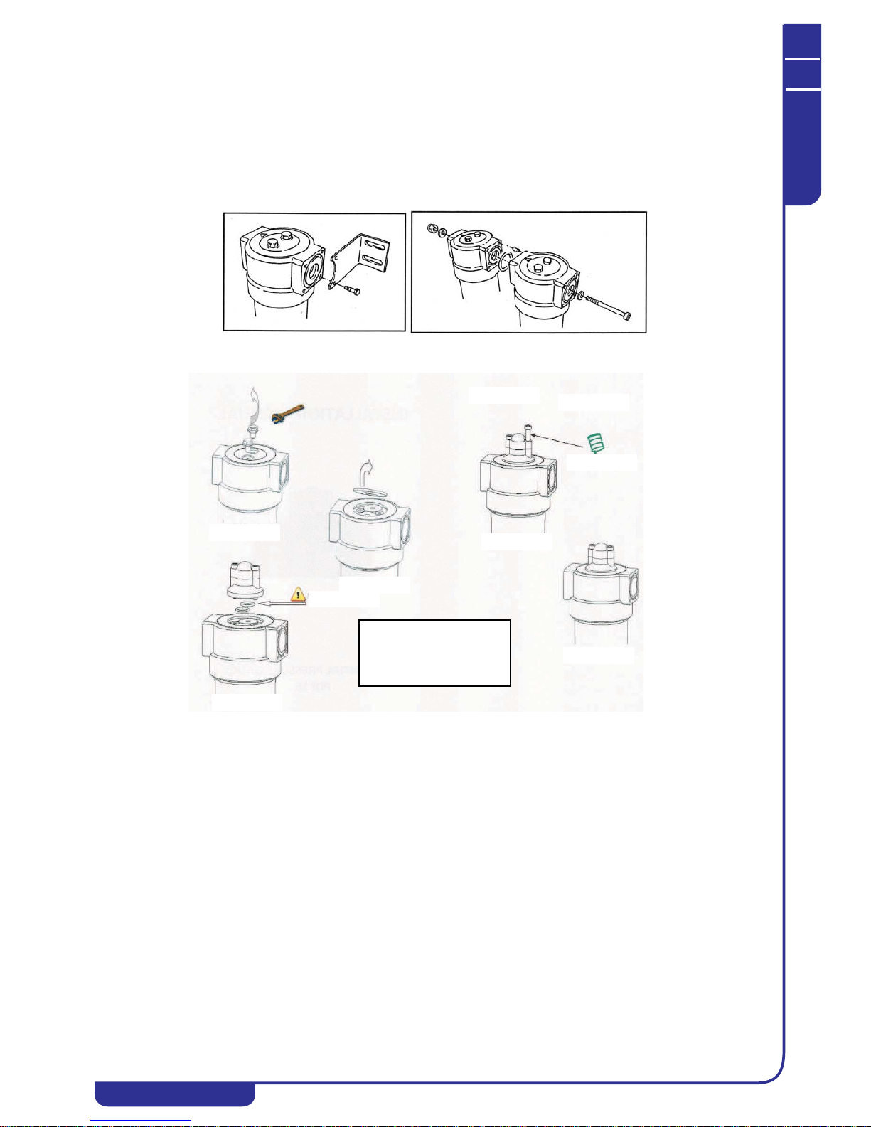
On Request:
1. Condensate separator
2. Wall mounting kit
3. Serie connection kit
4. Differential pressu
re gauge
2
3
2.
4.
5.
1.
3.
Vaselline
Torque 4-5 Nm
o-ring
ATTENTION!
Never proceed service and
maintenance work, if device
is still under pressure.
4. Mounting differential pressure indicator

MAINTENANCE AND OPERATING MANUAL
MAINTENANCE
HEF 005÷240
8
ENGLISH
EN
The data in this manual are not binding and may be changed by the manufacturer without notice. Reproduction of this manual is strictly prohibited.
MAINTENANCE
ATTENTION
Operations to be performed by qualified personnel. It’s necessary to gradually decrease the pressure inside the
filter slowly, in order to avoid damages to the element. A calibrated hole present in the filter head, warns the
operator with a whistle of air, in case he works with filter under pressure.
1.5 Cartridge replacement
Filters with grade P, M, S:
change the filter cartridge at least once a year or when the clogging device recom- mends it (if installed) -∆p
max. 0,6 bar.
Filters with grade A (activated carbon): the average life of the filtering element depends on the type of use
and varies from case to case. It is recommended that the cartridge is replaced at least once a year, but depending
on the application this can be required every 6 months.
1. Remove the bowl.
2. HEF 094 ÷240 - Remove the hexagonal nut.
3. Unthread the filter element.
4. Clean accurately the bowl and the drain device installed.
5. Clean accurately the head, in particular the seat for cartridge insertion.
6. Lubricate the O-rings and the sealing surfaces of the filter head and cartridge, use multipurpose grease
(SILICON FREE).
7. Fit the filter cartridge on the filter head simply by pressing, tightness is ensured by o-ring.
8. HEF 094÷240 - Tight the hexagonal nut fixing the element.
9. Fit the filter bowl and tight it accurately.
10.Stick the adhesive label showing the month and year for the next filtering element change (max. one
year) on the filter bowl.
ATTENTION
Pressurize the plant like shown at paragraph "Starting up" and check for air leakage.
ATTENTION
Always respect the regulations in force for disposing of polluting materials such as filtering elements etc.

MAINTENANCE AND OPERATING MANUAL
TECHNICAL DATA
HEF 005÷240
9
ENGLISH
EN
The data in this manual are not binding and may be changed by the manufacturer without notice. Reproduction of this manual is strictly prohibited.
TECHNICAL DATA
Working pressure 0 - 16 bar(g) 0 - 232 psi
Working temperature
with cartridges of grade P, M, S
1,5 - 65 °C 35 - 149°F
Working temperature
with cartridges of grade A
1,5 - 45°C 35 - 113°F
Filter
housing
model
Pipe size
Flow rate
(*)
Dimension [mm] Volume Mass
[Rp]
[m3/h]
A B C D min [l] [Kg]
HEF 005 3/8” 60 187 88 20 60 0,47 0,7
HEF 007 1/2” 78 187 88 20 60 0,47 0,7
HEF 010 3/4” 120 257 88 20 80 0,60 0,8
HEF 018 1” 198 263 125 32 100 1,57 1,8
HEF 030 1” 335 363 125 32 120 2,20 2,5
HEF 047 11/2” 510 461 125 32 140 2,80 2,5
HEF 070 11/2” 780 640 125 32 160 3,90 3,2
HEF 094 2” 1000 684 163 43 520 6,00 5,1
HEF 150 2” 1500 935 163 43 770 8,20 7,1
HEF 175 21/2” 1680 935 163 43 770 14,0 6,9
HEF 200 3 2160 795 240 59 630 20,0 12,9
HEF 240 3 2760 1000 240 59 780 24,40 14,0
(*) Flow rate condition: FAD 20 °C, 1 bar(A), operating pressure 7 barg, air operating
temperature 35 °C.
Filter
housing
model
Pipe size
Flow rate
(*)
Dimension [in] Volume Mass
[NPT] [SCFM] A B C D min [gal] [lb]
HEF 005 3/8” 35
7
3
/
8
3 1/
2
13
/
16
2 3/
8
0,13 1,54
HEF 007 1/2” 46
7
3
/
8
3 1/
2
13
/
16
2 3/
8
0,13 1,54
HEF 010 3/4” 71
10
2
/
16
3 1/
2
13
/
16
3 1/
8
0,16 1,76
HEF 018 1” 117
10
6
/164 15/
16
1 4/
16
3 7/
8
0,42 3,97
HEF 030 1” 197
14
1
/44 15/
16
1 4/
16
4 12/
16
0,58 5,51
HEF 047 11/2” 300
18
1
/44 15/
16
1 4/
16
5 1/
2
0,74 5,51
HEF 070 11/2” 459
25
3
/164 15/
16
1 4/
16
6 1/
4
1,03 7,05
HEF 094 2” 589
26
7
/
8
6 3/
8
1 6/
8
20 1/
2
1,59 11,24
HEF 150 2” 883
36
3
/
4
6 3/
8
1 6/
8
30 5/
16
2,17 15,65
HEF 175 21/2” 989
36
3
/
4
6 3/
8
1 6/830 5/
16
3,70 15,21
HEF 200 3 1271
31
1
/
4
9 1/
2
2 3/
8
24 3/
4
5,28 28,44
HEF 240 3 1624
39
1
/
4
9 1/
2
2 3/830 11/
16
6,45 30,87
(*) Flow rate condition: 68 °F, 14,6 psi(A), operating pressure 101,5 psig, air operating
temperature 95 °F.

MAINTENANCE AND OPERATING MANUAL
TECHNICAL DATA
HEF 005÷240
10
ENGLISH
EN
The data in this manual are not binding and may be changed by the manufacturer without notice. Reproduction of this manual is strictly prohibited.
CORRECTION FACTORS
Operating
pressure
[bar]
2345678910111213141516
Operating
pressure
[psi]
29 44 58 72 87 100 115 130 145 160 174 189 203 218 232
Correction
factor
0,38 0,50 0,63 0,75 0,88 1,00 1,13 1,25 1,38 1,50 1,63 1,75 1,88 2,00 2,13
80
RP 1/2”
Dmin
 Loading...