

Page 1

ALL INFORMATION CONTAINED IN THIS DOCUMENT IS PROVIDED AS IS WITHOUT WARRANTY OF ANY KIND.
THE CREATOR OF THIS DOCUMENT , HEREINAFTER REFERRED TO AS THE 'WRITER' HEREBY DISCLAIMS ALL
WARRANTIES, EXPRESSED, IMPLIED OR OTHERWISE, INCLUDING WARRANTIES OF MERCHANTABILITY,
FITNESS FOR A PARTICULAR PURPOSE, AND NON-INFRINGEMENT OF INTELLECTUAL PROPERTY RIGHTS. THE
WRITER DOES NOT ASSUME OR AUTHORIZE ANY OTHER PERSON TO ASSUME FOR IT ANY OTHER LIABILITY IN
CONNECTION WITH THIS CONTENT. IN NO EVENT SHALL THE WRITER BE LIABLE TO THE READER OF THE
CONTENT OF THIS DOCUMENT, OR ANY SUBSEQUENT USER, INCLUDING THE ULTIMATE END-USER, IN
CONTRACT, TORT, WARRANTY, STRICT LIABILITY, OR OTHERWISE FOR ANY SPECIAL, INDIRECT, INCIDENTAL
OR CONSEQUENTIAL DAMAGES, INCLUDING BUT NOT LIMITED TO, THE COST OF LABOR, REQUALIFICATION,
DELAY, LOSS OF PROFITS OR GOODWILL, EVEN IF THE WRITER IS ADVISED OF THE POSSIBILITY OF SUCH
DAMAGES. BY LOOKING AT THE CONTENT OF THIS DOCUMENT THE READER AGREES THAT THEY HAVE READ
AND AGREE TO THE ABOVE CONDITIONS ENTIRELY.
USER GUIDE
REV. 1.00
COMPRESS-IUV600S--1.00
COMPRESS IUV600S SERIES PRINTER
Page 2

Compress iUV600s Series User Guide
This page has been intentionally left blank
2
Page 3

Compress iUV600s Series User Guide
No part of this product or publication may be stored, reproduced, copied, or transmitted in any form or
by any means without the express permission of IMPRESSION TECHNOLOGY.
The product and the contents of this publication may be changed at any time without prior notification.
IMPRESSION TECHNOLOGY has made the best efforts to keep this publication free from error, but if you
find any uncertainties or misprints, please call us or the dealer from where you bought this equipment.
IMPRESSION TECHNOLOGY shall not be liable for any damages or troubles resulting from the use or misuse of this equipment or this manual either directly or indirectly.
Important
For Users in Europe
IMPORTANT:
This is a Class A product approved for industrial environments. In some
environments this product may cause radio interference in which case you may
be required to take measures to re-locate this product.
For Users in the United States
This equipment has been tested and found to comply with the limits for a Class A digital device,
pursuant to Part 15 of the FCC Rules. These limits are designed to provide reasonable protection
against harmful interference when the equipment is operated in a commercial environment.
This equipment generates, uses, and can radiate radio frequency energy and, if not installed and
used in accordance with the instruction manual, may cause harmful interference to radio
communications. Operation of this equipment in a residential area is likely to cause harmful
interference in which case the user will be required to correct the interference at his own expense.
Notice
Trademarks Mentioned in this Manual
• COMPRESS, iUV600s, WIMS, AOD, ACCULOK AND BMS are registered trademarks or product
names of IMPRESSION TECHNOLOGY.
• Centronics and BiCentronics are registered trademarks or product names of Centronics Data
Computer Corporation.
• Windows XP, Windows Vista, Windows 7 or greater and MS- DOS are registered trademarks or
product names of Microsoft Corporation.
• Intel and Pentium are trademarks or registered trademarks of Intel Corporation.
• Other company and product names may be registered trademarks or product names.
•
i
Page 4

Compress iUV600s Series User Guide
Warranty
IMPRESSION TECHNOLOGY warrants part repair or replacement as a sole measure only if a failure
is found in the system or in the materials and workmanship of the product the seller produced.
However, if the cause of failure is uncertain or cannot be conclusively proved to be directly related
to defect in workmanship any part repair or replacement shall be solely at the discretion of
Impression Technology.
The warranty shall not apply to any direct or indirect loss, or compensation for the loss due to the
product that has been subject to misuse, neglect, or improper alternation whether directly or
indirectly.
ALL INFORMATION CONTAINED IN THIS DOCUMENT IS PROVIDED AS IS WITHOUT WARRANTY OF
ANY KIND. THE CREATOR OF THIS DOCUMENT , HEREINAFTER REFERRED TO AS THE 'WRITER'
HEREBY DISCLAIMS ALL WARRANTIES, EXPRESSED, IMPLIED OR OTHERWISE, INCLUDING
WARRANTIES OF MERCHANTABILITY, FITNESS FOR A PARTICULAR PURPOSE, AND NONINFRINGEMENT OF INTELLECTUAL PROPERTY RIGHTS. THE WRITER DOES NOT ASSUME OR
AUTHORIZE ANY OTHER PERSON TO ASSUME FOR IT ANY OTHER LIABILITY IN CONNECTION
WITH THIS DOCUMENT CONTENT. IN NO EVENT SHALL THE WRITER BE LIABLE TO THE READER
OF THE CONTENT OF THIS DOCUMENT, OR ANY SUBSEQUENT USER, INCLUDING THE ULTIMATE
END-USER, IN CONTRACT, TORT, WARRANTY, STRICT LIABILITY, OR OTHERWISE FOR ANY
SPECIAL, INDIRECT, INCIDENTAL OR CONSEQUENTIAL DAMAGES, INCLUDING BUT NOT LIMITED
TO, THE COST OF LABOR, REQUALIFICATION, DELAY, LOSS OF PROFITS OR GOODWILL, EVEN IF
THE WRITER IS ADVISED OF THE POSSIBILITY OF SUCH DAMAGES. BY LOOKING AT THE CONTENT
OF THIS DOCUMENT THE READER AGREES THAT THEY HAVE READ AND AGREE TO THE ABOVE
CONDITIONS ENTIRELY.
Limitations
ii
Page 5

Compress iUV600s Series User Guide
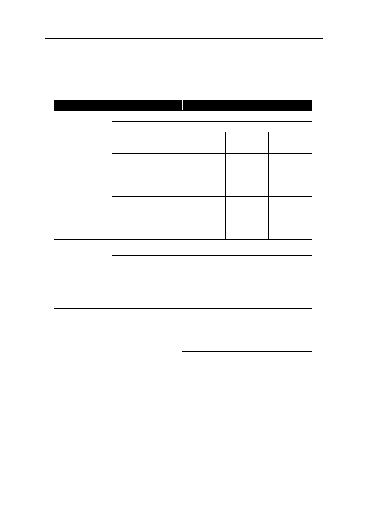
Section
Contents
1 Safety Instructions
Explains types of warnings, cautions and warnings labeled on the
printer
2 Product Overview
Explains the features, part names, and functions of the printer.
3 Initial Setup and Basic
Operations
Explains the procedures for the initial setup & basic operations
of the printer.
4 Printing on substrates
Explains the procedures of preparation for & printing to
substrates with the printer.
5 Maintenance
Explains daily and other periodical maintenance of the printer.
9 Troubleshooting
Explains troubles that may occur when using the printer and
how to solve them.
10 Appendix
Printer specifications
About this
Manua
l
A. Purpose and Target Readers
This manual explains the preparations and procedures for operating the Compress iUV600s series
printer.
This is a common User Guide for the Compress series of printers. Unless specifically mentioned to
the contrary, the descriptions in this manual are common for all Compress series models.
This manual is designed to assist the end user in the use, maintenance and general troubleshooting
of the Compress series printers. Before using the Compress series printer you are required to read
and fully understand the contents and directions in this manual.
B. Manual Configuration
iii
Page 6

Compress iUV600s Series User Guide
Revision Date
Summary of Changes
15th October 2015
Initial release
C. Document Change History
This version of the document replaces and obsoletes all previous versions. The following table
describes the most recent changes:
iv
Page 7

Compress iUV600s Series User Guide
Symbol
Meaning
Must be followed carefully to avoid death or serious bodily
injury or catastrophic damage to your equipment.
Must be observed to avoid slight or moderate bodily injury or
damage to your equipment.
Contains important information and useful tips on the operation
of the product
Indicates useful tips for operating or understanding the
equipment or getting the best performance from your
equipment.
Indicates reference pages in this manual
WARNING
CAUTION
NOTE
TIP
D. Manual Notation
The following symbols are used in this manual for easier understanding of the information.
v
Page 8

Page 9

Compress iUV600s Series User Guide
GENERAL TABLE OF CONTENTS
1. Safety Instructions .................................... 7
1.1 Introduction .......................................................................... 7
1.2 Warnings, Cautions and Notes .............................................. 7
1.3 Important Safety Instructions ............................................... 8
1.4 Warning Label types and meanings .................................... 11
1.4.1 Handling the Warning Labels .............................................. 11
1.4.2 Locations of Warning Labels ............................................... 12
2. Product Overview ................................... 13
2.1 Introduction ........................... Error! Bookmark not defined.
2.2 Features .............................................................................. 13
2.2.1 High Resolution Image Quality ........................................... 13
2.2.2 Ink Supply System .............................................................. 13
2.2.3 Operation Efficiency Improvement ..................................... 13
2.2.4 Operability Improvement ................................................... 13
2.3 Part Names and Functions .................................................. 14
2.3.1 Front Section ..................................................................... 15
2.3.2 Rear Section ....................................................................... 17
2.3.3 WIMS ................................................................................. 18
2.3.4 Operation Panel ................................................................. 20
2.4 Printer Status ...................................................................... 23
2.4.1 Normal .............................................................................. 23
1
Page 10

Compress iUV600s Series User Guide
2.4.2 Setup Menu ....................................................................... 23
2.4.3 Changing Printer status ...................................................... 23
3. Initial Setup & Basic Operations .............. 24
3.1 Introduction ........................................................................ 25
3.2 Before you Get Started ....................................................... 25
3.2.1 Commit to Maintenance .................................................... 25
3.2.2 Get to Know your iUV600s ................................................. 25
3.3 Choosing a Place for the Printer .......................................... 28
3.3.1 Installation Environment Requirements ............................. 28
3.3.2 Required Space .................................................................. 29
3.4 Minimum Computer Requirements .................................... 31
3.5 Basic Operations ................................................................. 32
3.5.1 Switching the Printer ON .................................................... 32
3.5.2 Switching the Printer OFF. .................................................. 34
3.5.3 Connecting the Printer to the PC ........................................ 35
3.5.4 Confirming Default Settings ............................................... 37
3.5.5 Performing a Head Clean from the Operation Panel ........... 42
3.6 Initial Setup ......................................................................... 44
3.6.1 Removal of Shipping Tape .................................................. 44
3.6.2 Remove Carriage Lock Bracket ........................................... 45
3.6.3 Initial Ink Fill Process - Colours ........................................... 46
3.6.4 Initial Ink Fill Process – White ............................................. 50
3.6.5 Loading Media for Printing ................................................. 52
3.6.6 Checking media height ....................................................... 53
3.6.7 Performing a Nozzle Check Test Print ................................. 55
3.6.8 Examining a Nozzle Check Test Print .................................. 57
2
Page 11

Compress iUV600s Series User Guide
3.6.9 Bi-Directional (Bi-D) Adjustment ........................................ 58
3.6.10 Installing & Using Printer Drivers........................................ 68
4. Printing to Substrates ............................. 85
4.1 Introduction ........................................................................ 86
4.2 Prepare Your Image ............................................................. 86
4.3 Substrate Preparation ......................................................... 89
4.4 Load substrate/template to the printer .............................. 90
4.4.1 Put the template onto the Platen ....................................... 90
4.4.2 Adjust Printing Bed Height / Move Platen to the Top of Page
position 91
4.5 Print Your Image .................................................................. 91
4.6 Post-Printing ........................................................................ 92
4.7 Cancelling a Print Job .......................................................... 93
4.7.1 Introduction ....................................................................... 93
4.7.2 Cancelling the Print Job ...................................................... 93
4.7.3 Re-starting the Printer after Cancelling a Print Job ............. 93
5. General Care & Maintenance .................. 94
5.1 Introduction ........................................................................ 95
5.2 Execute a Print Head Clean at the end of production ......... 95
5.3 Run the Nozzle Check test print each day before starting
production ................................................................................... 95
5.4 Maintaining the Ink System ................................................. 95
5.4.1 Accessing the Capping Station ............................................ 95
3
Page 12

Compress iUV600s Series User Guide
5.4.2 Cleaning the Flushing Tray ................................................. 97
5.4.3 Cleaning the Wiper and Head Cap ...................................... 98
5.4.4 Manual Print Head Guards Clean ........................................ 99
5.4.5 Parking the Print Head ..................................................... 100
5.4.6 Emptying the waste ink container ....................................... 101
5.5 Other Maintenance Items ................................................. 102
5.5.1 Powerful Head Cleaning ................................................... 102
5.5.2 Ink Charge ....................................................................... 104
5.5.3 Clean the CR Encoder Strip ............................................... 110
5.5.4 Clean the CR Guide (X Rail) ............................................... 113
5.5.5 Clean the CR Drive Belt, Roller and Pulley ........................ 114
5.6 General Care ..................................................................... 114
5.6.1 Environment .................................................................... 114
5.6.2 Clean your Compress iUV600s™ ....................................... 115
5.6.3 Avoid White Ink Separation .............................................. 115
5.6.4 Replace WIMS filter ......................................................... 115
5.6.5 Empty & Wash White Ink Container ................................. 116
5.6.6 Ink Levels ......................................................................... 116
5.6.8 Flushing the printer ......................................................... 116
5.7 Transportation of Printer .................................................. 118
6. Troubleshooting .................................... 119
6.1 Introduction ...................................................................... 120
6.2 Troubleshooting with Error Messages .............................. 120
6.2.1 Operation Status .............................................................. 121
6.2.2 Errors with Message ......................................................... 122
6.2.3 Data Errors ....................................................................... 124
4
Page 13

Compress iUV600s Series User Guide
6.2.4 Command Errors .............................................................. 125
6.2.5 Errors Requiring Reboot ................................................... 126
6.3 Troubleshooting Without Error Messages ........................ 134
6.3.1 Initial Operation Problems ................................................ 134
6.3.2 Printing Problems ............................................................ 137
6.3.3 Noise Problems ................................................................ 152
6.3.4 Problems with Curing / Washing ........... Error! Bookmark not
defined.
6.3.5 Other Problems................................................................ 153
7. Appendix .............................................. 154
7.1 Product Specifications ....................................................... 155
7.1.1 Main Unit Specifications .................................................. 155
7.1.2 Print Operation Specifications .......................................... 155
7.1.3 Printer physical specifications .......................................... 156
7.2 Interface Specifications ..................................................... 158
7.2.1 USB Interface Specifications ............................................. 158
7.2.2 Network Interface Specifications ...................................... 159
7.3 Options/Supplies List ......................................................... 159
7.3.1 Options ............................................................................ 159
7.3.2 Supplies ........................................................................... 160
5
Page 14

Compress iUV600s Series User Guide
6
Page 15
Safety Instructions Compress iUV600s Series User Guide
Safety Terms
Details
Must be followed carefully to avoid death or serious bodily injury
Must be observed to avoid slight or moderate bodily injury or damage
to whole or part of the product
Contains important information and useful tips on the operation of the
product
TABLE 0-1 SAFETY TERMS
WARNING
CAUTION
WARNING
NOTE
Safety Instructions
1.0 Introduction
This chapter explains the meaning of safety terms for personnel who install, operate, or maintain this
equipment, important safety instructions, and the warning labels attached to the equipment.
Make sure to follow all instructions and warnings on this manual when installing, operating, or maintaining
the equipment.
1.1 Warnings, Cautions and Notes
Safety terms in this manual and the contents of warning labels attached to the printer are categorized into
the following three types depending on the degree of risk (or the scale of accident).
Read the following explanations carefully, and follow the instructions in this manual.
7
Page 16

Compress iUV600s Series User Guide Safety Instructions
WARNING
1.2 Important Safety Instructions
General safety instructions that must be observed to use the equipment safely are explained below.
ALWAYS CONSULT YOUR PRODUCT REPRESENTATIVE PRIOR TO SWITCHING ON YOUR MACHINE
Do not place the printer in the following areas. Doing so may result in the printer tipping or falling
over and causing serious injury.
Unstable or loose surfaces
Angled surfaces
Areas subject to vibration by other equipment
Do not stand on or place heavy objects on your printer. Doing so may result in the printer tipping or
falling over and causing injury.
Do not look directly at the LED UV lamp whilst the machine is in operation, this can be damaging to
human eyes. The use of UV proof sunglasses is strongly recommended
Do not cover the ventilation hole of your printer with cloth, such as a blanket or table cloth. Doing so
could obstruct ventilation and cause fire.
Do not place the printer in humid and dusty areas. Doing so may result in electrical shock or fire.
Make sure to use the power cable packed with the printer you purchased. Not doing so may result in
electrical shock or fire.
Do not use the power cable if it is damaged in any way. Doing so may result in electrical shock or fire.
Do not insert or drop metal or objects which are easily combustible through the openings such as the
ventilation hole of your printer. Doing so may result in electrical shock or fire.
Do not operate the printer if it has been contaminated by foreign substances or liquid spills as doing
so may result in electrical shock or fire. Immediately turn off the power switch, disconnect the power
plug from the electric socket, and contact your authorized DTG Dealer.
Make sure to use only the specified power supply (AC 100 V - 120 V or AC 220 V - 240 V). If the power
supply other than the specified voltage is used, it could cause an electric shock and fire.
Make sure to double check LED curing lamp voltages are set for your specific countries voltage rating.
Take power for the printer directly from the power socket (AC 100 V - 120 V or AC 220 V - 240 V). Do
not use complex multiple plugs on the same socket. This could generate heat and might cause fire.
Make sure that the following is performed before parts replacement.
Turn off the power to the printer.
Remove the power cable from the power outlet. Not doing so may cause electric shock or
damage to the electric circuit.
Unplug the cables connected to the printer. Failure to do so could result in damage to the
printer.
8
Page 17

Safety Instructions Compress iUV600s Series User Guide
CAUTION
Pay attention to the following when handling the power cable:
Do not do anything forcefully (e.g. pull, bend, twist) to the power cable
Do not place heavy objects on the power cable
Do not route the power cable near heat sources
Pay attention to the following points while handling the power supply plug. Not going so may result
in electrical shock or fire:
Make sure that the power cable / plug is not contaminated by any foreign substances such as
dust etc.
Make sure that the power plug is correctly connected to the power socket.
Pay attention when handling inks so that ink does not get into the eyes or spill on your skin. If the ink
does get into eyes or onto skin, immediately wash the affected area with water. The inks may cause
mild skin irritation and/or inflammation of the eyes. Consult with medical personnel in the case of
any adverse reaction.
Be careful to ensure that fingers are not caught in the opening when lifting and closing the top cover
of the printer.
Do not use strong solvents such as thinners, benzene or alcohol on the printer. These products may
damage the paint on the printer.
Take care that moisture does not enter the printer. There is a risk of a short circuit of the electrical
circuit(s) within the printer if this occurs.
Ensure that the printer is always kept in a horizontal position, even whilst it is being lifted or moved.
Do not leave the printer on a slanted surface. Do not leave the printer upside down. Doing so may
cause ink leakage and / or trouble that cannot be restored, as the printer is originally assembled in the
factory with a high accuracy of 1/100 mm.
Ensure all packing materials are removed from the printer before lifting from it’s crate. If the printer
is lifted with materials attached, it may slip from the hands and be damaged.
Assembling and disassembling of the printer are possible only for the parts that disassembling
procedures are shown in this manual, and should be undertaken only by DTG authorized and trained
professionals. Do not disassemble any frame parts or parts that disassembling procedures are not
shown in this manual. Doing so may cause trouble that cannot be restored, as the printer is originally
assembled in the factory with a high accuracy of 1/100 mm.
Do not touch the elements on the circuit board with bare hands. Doing so may cause static
electricity and cause catastrophic invisible damage.
Do not press the transparent film on the damper assembly with your hands. Doing so may discharge the
ink filled inside the damper assembly or damage the pressure valve.
Be careful not to damage the transparent film on the damper assembly.
Do not touch the nozzle plate of the print head, keep free from dust.
There is ink in the tubes throughout the printer. Be careful that the ink is not spilled from any tube
outlet onto the printer or items close to the printer.
9
Page 18

Compress iUV600s Series User Guide Safety Instructions
If you need to operate the printer with the cover removed for maintenance or repair, be careful not to
get injured by any moving parts.
Never lubricate the printer mechanism with anything other than that designated by Impression
Technology. Doing so may damage the parts or shorten the lifetime of the parts and / or printer.
If the power board assembly needs to be removed, remove the power cable and wait for 5 minutes or
more before taking it out; this will discharge the residual electrical charge of the electrolytic capacitor.
Touching the board before the capacitor discharges may cause electric shock or death.
When connecting or removing an FFC type cable on a main board assembly connector, make sure to
connect or remove the cable perpendicular to the connector. Connecting or removing at a slant may
damage, break or short-circuit the inner terminal of the connector and may damage the components
on the board.
When connecting or removing an FFC type cable on the CR board assembly connector, make sure to
connect or remove the cable perpendicular to the connector. Connecting or removing at a slant
angle may damage, break or short-circuit the inner terminal of the connector. That may damage the
components on the board.
Make sure there is sufficient space around the printer when performing maintenance work.
Maintenance must be done by more than two person for the following work.
When disassembling or reassembling the product
When packing the printer for transportation
10
Page 19

Safety Instructions Compress iUV600s Series User Guide
Ref
Warning Label Type
A
Using this area as a lift point will cause damage to the printer.
B
Do not touch anything in this area unless instructed.
C
Dangerous voltages present in this area.
D
Fingers may be trapped and ripped off in this area.
TABLE 0-2 WARNING LABEL TYPE
A
B
C
D
NOTE
1.3 Warning Label types and meanings
The handling, attachment locations, and types of warning labels are explained below.
Warning labels are attached to areas where care should be taken. Read and understand the positions and
contents thoroughly before maintenance operation.
1.3.1 Handling the Warning Labels
Make sure to note the following when handling the warning labels.
Make sure that all warning labels can be recognized. If text or illustrations cannot be seen clearly,
clean or replace the label.
When cleaning warning labels, use a cloth with water or neutral detergent. Do not use any solvent or
gasoline products.
If a warning label is damaged, lost, or cannot be recognized, replace the label.
11
Page 20

Compress iUV600s Series User Guide Safety Instructions
Ref
Warning Label Type
A
Using this area as a lift point will cause damage to the printer.
B
Do not touch anything in this area unless instructed.
C
Dangerous voltages present in this area.
D
Fingers may be trapped and ripped off in this area.
B
C
D
B
A
D
A
1.3.2 Locations of Warning Labels
The locations of warning labels are shown below.
12
Page 21

Product Overview Compress iUV600s Series User Guide
Product Overview
1.4 Features
The features of the printer are explained below.
1.4.1 High Resolution Image Quality
This model uses the drop on-demand piezo head with a high performance coated nozzle plate.
The ability to eject >40pl droplet size enables excellent white ink delivery.
1.4.2 Ink Supply System
This model uses a microprocessor controlled pressurised color ink supply system and a patented White
Ink Management System (WIMS) utilising high performance brushless motors designed to provide trouble
free, accurate white ink delivery at all times.
1.4.3 Operation Efficiency Improvement
Loading media onto the media platens is done away from the printer and then slipped into the ACCULOK
platen locating and holding system.
1.4.4 Operability Improvement
The simple and intuitive GO/NO GO system uses two high brightness LED’s to indicate to the user
whether or not the printer is ready to receive a print job.
Sending a print when either LED is not green will result in a failed print job.
13
Page 22

Compress iUV600s Series User Guide Product Overview
Left
Upper
Rear
Front
Right
Lower
FIGURE 0-1 PRINTER ORIENTATION
1.5 Part Names and Functions
Part names and functions are explained in this section.
For the directions described in this document, refer to the following orientation figure:
14
Page 23

Product Overview Compress iUV600s Series User Guide
FIGURE 0-2 PRINTER FRONT
SECTION PARTS
Emergency stop
LCD and keypad
Bed up/down
buttons &
status light
Bed Load/eject
status light
Waste ink
access
Pressure reset
and status light
WIMS &
Bulk ink
system
Media
tray
1.5.1 Front Section
access and
cooling system
buttons &
15
Page 24

Compress iUV600s Series User Guide Product Overview
Name
Function
Emergency stop
This button removes mains power from the printer in an emergency.
Bed UP button
This button causes the motorised bed to move upwards and decrease the gap
between the print head and media.
Bed DOWN button
This button causes the motorised bed to move downwards and increase the gap
between the print head and media.
Bed STATUS light
This solid state lamp indicates the status of the bed height and it’s relation to
the head safety beam.
GREEN indicates that the media is at, or lower than, the optimum print height.
RED indicates that the media is at, or higher than, the recommended safe print
height.
AMBER indicates that the media height/head protection system has been
disabled and only the bed down button can be used. This mode is accessed by
depressing the bed UP button and the bed DOWN button at the same time
Bed LOAD button
This button causes the printer to move the bed into the start of print position in
which the top most area of the bed will be aligned with the top of the selected
print position.
Bed EJECT button
This button causes the printer to move the bed into the end of print position in
which the bottom most area of the bed will be situated in the entry point of the
printer.
Bed STATUS light
GREEN indicates that the bed is loaded in to the printer and the printer is ready
to print.
RED indicates that the bed is NOT loaded in to the printer and the printer will
not be able to print correctly, an error will occur if a print is sent to the printer
when the bed status light is red.
RED FLASH – the Bed STATUS light will flash red 1 times immediately when the
printer is powered on. This is an indicator that the printer is an X series printer.
Pressure Reset
Button & Status
Light
The CMYK pressure system comprises a pressure control board, DC motor driven
diaphragm pump and pressure limit switch. There is also a reset switch, warning
beeper and a status indicator light. The system will pump for a limited time to
build the correct CMYK ink pressure level, if this is not achieved the indicator
lamp will flash red, the beeper will sound and the pump will stop. This is to alert
the user to a pressure loss. This can be reset by pressing & holding the reset
switch for 1-2 seconds which will cause the pump to start again and the light will
go yellow. When the correct pressure is reached and all is well the indicator
lamp will pulse green.
TABLE 0-1 PRINTER FRONT SECTION PART FUNCTION
16
Page 25

Product Overview Compress iUV600s Series User Guide
Name
Function
AC mains power inlet
For inserting the mains power cable plug.
Network interface connector
Connector to connect a network interface cable.
USB cable connector
Connector to connect a USB cable.
FIGURE 0-3 PRINTER REAR
SECTION PARTS
Media tray
Mains
inlet
Ethernet and
USB
WIMS unit
WIMSPump
and stirrer
Colour ink
bottles
Optical
sensor
Waste ink
access
Pressure reset
and status light
1.5.2 Rear Section
access and
cooling system
TABLE 0-2 PRINTER REAR SECTION PARTS FUNCTION
17
Page 26

Compress iUV600s Series User Guide Product Overview
FIGURE 0-4 WIMS PARTS
Magnetic
Motor
WIMS Pump
WIMS mode
button
WIMS
Status Light
WIMS Rest
Setting
WIMS Stir
Setting
WIMS Filter
Provision for clear
Ink bottle
WIMS Pump
WIMS power
connector/status light
1.5.3 WIMS
Stirrer
18
Page 27

Product Overview Compress iUV600s Series User Guide
Name
Function
WIMS stirrer power
This indicator is BLUE during standby and RED when the printer is active. This
indicator is an integral part of the WIMS power plug.
WIMS stirrer
This assembly stirs the white ink by rotating the stirrer paddle clockwise for
approximately 10 seconds and then anti-clockwise for approximately 10
seconds. This is repeated while the unit is active
WIMS pump
This assembly circulates the white ink by peristaltic action to prevent the heavy
white pigment from settling in the pipes and bulk container.
WIMS Mode button
This button has two functions. In normal operating mode it will over-ride all
settings and force the pump and stirrer to operate continuously.
This mode is entered into, and cancelled, by pressing and holding the button for
more than three seconds. Diagnostic mode is entered by pressing the button
whilst power is being applied to the WIMS.
WIMS status light
GREEN indicates that WIMS has operated for a total of less than 1500
hours.
AMBER indicates that WIMS has operated for more than 1500 but less than
1700 hours
RED indicates that WIMS has operated for more than 1900 hours and that the
peristaltic pump tube should be replaced as soon as possible.
WIMS rest setting
This selects the length of time in segments of one hour for which the WIMS will
be at rest between stirring and circulating the ink.
WIMS stir setting
This selects the length of time in two minute segments for which the WIMS will
be actively stirring and circulating the ink.
WIMS Filter
The WIMS filter is a 20µm in-line filter capsule and is used as a protection
measure for the print head and dampers. Particles or other contaminants
which may be present in or ingress into the white ink should be trapped by the
WIMS filter and therefore not progress through to the dampers and print head.
The WIMS filter should be replaced at least monthly, and more frequently
during high volume consumption of white ink.
TABLE 0-3 WIMS PARTS FUNCTION
19
Page 28

Compress iUV600s Series User Guide Product Overview
NOTE
1
2
3
4
5
6
7
8
9
10
11
FIGURE 0-5 OPERATION PANEL
1.5.4 Operation Panel
The operation panel (LCD & Keypad) is used to set operational conditions, display the status of the
printer, and set other functions.
explained below.
The names and functions of the operation keys and status lamps are
1.5.4.1 Operation Keys
Some keys have multiple functions and names depending on the printer status (normal or setup menu
display). See 1.6 "Printer Status" p.23 for more details.
20
Page 29

Product Overview Compress iUV600s Series User Guide
No.
Name
Normal Operation Function
Setup Menu Display Function
1
[Menu] key
Changes the LCD monitor display to
setup menu status.
Changes the setup menu display
status to normal status.
2
[Enter] key
- Selects the menu to be set and
shifts to the next hierarchy.
- Determines and saves the
parameter value.
[Cleaning] key
If held down for 2 seconds or more,
starts cleaning the printer
head.(note: platen should be loaded
and hood should be lifted to switch
of the UV lamps)
-
3
[Cancel] key
- During printing: Terminates printing
forcibly and deletes 1 file of
remaining data.
- During reception/analysis: Deletes
the data that has been already
received/analysed and ignores 1 file
of data received after that.
- Returns to the previous menu
hierarchy. Changed parameter
values are disabled.
- Changes the setup menu display
status to normal status.
[Cut] key
DO NOT USE
-
4
[Back] key
DO NOT USE except to toggle Roll
Lamp (below) to Green
Changes the menu in reverse order.
5
[Next] key
DO NOT USE
Changes the menu in forward order.
6
[Reverse feed] key
DO NOT USE
-
[ ˄ ] key
DO NOT USE
- Changes the setting value in the
forward direction.
- Increases the value when inputting
values.
7
[Forward feed] key
DO NOT USE
-
[ ˅ ] key
-
- Changes the setting value in the
reverse direction.
- Decreases the value when
inputting values.
8
[Power] key
Turns the printer on and off.
Turns the printer on and off.
TABLE 0-4 OPERATION KEYS FUNCTIONS
21
Page 30

Compress iUV600s Series User Guide Product Overview
No. Name Color Status Function
1
Power lamp
Green
On
The printer is switched on.
Blinking
An error has occurred. Error content will be displayed on
the LCD monitor.
Off
The printer is switched off.
2
Data lamp
Red
On
- The printer is analyzing received data.
- The printer is printing data.
Blinking
The printer is receiving data.
Off
The printer is not receiving, analyzing or printing data.
3
Roll lamp
Green
On
The printer is set to roll media.
Off
The printer is set to cut media. INCORRECT SETTING
Off
The printer is set to roll sheet. INCORRECT SETTING
Off
The plot mode is set to High speed. INCORRECT SETTING
4
LCD monitor
- - This monitor displays the operation status and error
messages of the printer.
1.5.4.2 LCD Monitor and Status Lamps
TABLE 0-5 LCD MONITOR & STATUS LAMPS
22
Page 31

Product Overview Compress iUV600s Series User Guide
NOTE
1.6 Printer Status
The status of the printer is explained below.
1.6.1 Normal
Indicates that the printer can print when the platen is loaded.
Both indicator LED’s (Power lamp & Roll Lamp) are green.
1.6.2 Setup Menu
The settings required for normal printing are usually made via the printer driver or RIP, but can also be
made using the operation panel.
1.6.3 Changing Printer status
(1) Normal → Setup Menu Display
When the printer is in “normal” mode, press the [Menu] key
The operation panel will shift to the setup menu display and show "*Me nu * T es tP lo t >".
(2) Setup Menu Display → Normal
While the printer is in setup menu display, if either of the following operation is done, the operation
panel shifts to Normal display.
[Menu] key on operation panel is pressed.
In the Setup menu, leave the keys untouched for three minutes.
For details on Status message, refer to 5.2.1 "Operation Status" p.121
23
Page 32

Compress iUV600s Series User Guide Initial Setup & Basic Operations
2. Initial Setup & Basic Operations
24
Page 33

Initial Setup & Basic Operations Compress iUV600s Series User Guide
2.1 Introduction
This chapter provides information on the initial setup and basic operation of the iUV600s Printer.
It is highly recommended that the initial setup of the printer be performed by a Compress trained &
authorized technician. Damage caused by incorrect setup will not be warrantied.
Initial setup should be undertaken in the following order:
1. Position the printer 2.3 "Choosing a Place for the Printer" p.28
2. Remove packaging materials 2.6.1 "Removal of Shipping Tape" p.44
3. Load colour inks (before power is applied to the printer) 2.6.3 “Priming the cooling
system.
4. Before the LED UV lamps can be operational you must first prime the entire lamp cooling
system. The reservoir for the pump is located in the waste tank bay via the small grey door.
The Pump unit and reservoir are located to the right as shown below
Reach in and lift the reservoir bottle from its location, you may need to angle the bottle to aid in the
removal. Bring bottle out as shown below.
25
Page 34

Compress iUV600s Series User Guide Initial Setup & Basic Operations
You will notice a green solution in the bottle, this is anti freeze, simply fill the bottle ¾ full with
distilled water, reattach the lid and then return bottle to the original location.
To Prime the LED lamp cooling system;
1- Release the E stop only, do not power up printer.
2- Raise the machine lid. You should see 2x blue LED’s illuminated.
3- Release and move carriage away from the capping station as per picture below. At this point
you will hear the pump running, this means that the system will be starting to prime, look at
the cooling tubes connecting to the lamps, once the air has been flushed from the tubing,
the system is primed, at the same time checking for leaks, allow the pump to continue
running for the entire 4 minutes (cooling down period) after which the pump will
automatically stop. Tubes should be solid and NO air visible.
4- Check the reservoir bottle and ensure that fluid is visible
26
Page 35

Initial Setup & Basic Operations Compress iUV600s Series User Guide
5. Initial Ink Fill Process - Colours" p.45
6. Load white ink 0 "3 .6. 5 Initial Ink Fill Process – White" p.50
7. Load media for printing 5.6.6 "Loading Media for Printing" p.52
2.2 Before you Get Started
2.2.1 Commit to Maintenance
Your Compress iUV600s™ represents a significant investment, not only of your money but also of your
commitment to your new business opportunity with the Compress iUV600s™.
Whilst the mechanics of the printing unit of the iUV600s are similar to that of a normal inkjet printer,
printing on rigid substrates is not the same as printing on paper. Various substrates can generate
more dust, it may require a much greater volume of ink, and the application of primers can become
airborne if applied by spraying and can ingress into the iUV600s. Each of these factors individually can
cause problems with your Compress iUV600s™, and in combination can be critical to the ongoing
27
Page 36

Compress iUV600s Series User Guide Initial Setup & Basic Operations
Left
Upper
Rear
Front
Right
Lower
FIGURE 2-1 PRINTER ORIENTATION
Top Cover (Lid)
LCD and keypad
Bulk ink
system
operation of the printer. All is not lost, however! A few minutes of your time each day spent
undertaking some basic maintenance tasks on the printer will ensure it’s continued optimal
performance. Please refer to the sections within this User’s Guide on Preventative Maintenance for
further information.
2.2.2 Get to Know your iUV600s
Starting a new business or adding to your existing product line with the Compress iUV600s™ is a very
exciting, and potentially very profitable time. Don’t get too carried away though and start accepting
orders before you even have your printer. Allow plenty of time to become familiar with your printer
and to learn not only the basics, but also the variables that can impact on your finished product.
These variables include image types, substrate types, your operating environment, and substrate
preparation. Thoroughly read this manual, ask questions of your Compress Technician or Distributor,
talk to other users. Be prepared for a learning curve. Be realistic about deadlines when accepting
orders and allow yourself sufficient time (and perhaps a couple of extra blank products) to complete
the order.
28
Page 37

Initial Setup & Basic Operations Compress iUV600s Series User Guide
Media tray
Mains
inlet
Ethernet
and USB
WIMS unit
Pump and
stirrer
Colour ink
bottles
Optical
sensor
Waste ink
cooling system
access
Pressure reset
and status light
FIGURE 2-3 PRINTER REAR
SECTION PARTS
FIGURE 2-2 PRINTER FRONT SECTION
PARTS
access and
29
Page 38

Compress iUV600s Series User Guide Initial Setup & Basic Operations
30
Page 39

Initial Setup & Basic Operations Compress iUV600s Series User Guide
Installation space
5m
2
or more, 2.6m or more is required for the width
Floor loading capability
Up to 3000Pa (450kgf/m2) or more
Electrical
specifications
Voltage
AC 100 V - 120 V ± 10% or AC 200 V - 240 V ± 10% (LED lamps not
auto switching and must be configured prior to switching on the
machine, contact your product representative for more details)
Frequency
50/60Hz ± 1Hz
Capacity
Up to 4A or more
Environmental conditions
Temperature
Humidity
Operation environment
18º C (64F) to 30ºC (86F)
20% to 80%, with no
condensation
Printing accuracy warranty range
18ºC (64F) to 28ºC
(82.4F)
40% to 60%, with no
condensation
Rate of change
2ºC per hour or less
5% per hour or less
WARNING
2.3 Choosing a Place for the Printer
Do not place the printer in a location under the following conditions. Doing so may cause the
product to fall over, become damaged, or cause serious injury:
o Unstable or shaky surfaces.
o Slippery, slanted or angled surfaces.
o Locations that are subject to vibration from other products.
Do not stand, or lean, on the printer or place any objects on it. Doing so may cause it to fall
over, become damaged, or cause injury.
Do not cover any ventilation holes or slots of the printer with anything at all. Doing so could
prevent the printer from ventilating and cause fire.
Keep the printer away from damp, humid or dusty areas. Failure to do so may result in electrical
shock or fire.
2.3.1 Installation Environment Requirements
Choose a place for printer installation following the requirements of the table below.
TABLE 2-1 INSTALLATION ENVIRONMENT REQUIREMENTS
31
Page 40

Compress iUV600s Series User Guide Initial Setup & Basic Operations
NOTE
NOTE
Avoid the following temperature and humidity conditions. Otherwise, printed images may appear
differently from what you expect and machine operation may be erratic or incorrect.
Places where sudden changes in temperature or humidity are expected, even if the condition is
within the range specified within this document.
Places where direct sunlight or excessive lighting conditions are expected
Places where air conditioners blow directly.
Impression Technology strongly recommends that the printer should be installed where air
conditioning airflow, humidity and temperature can be adjusted easily.
2.3.2 Required Space
Install the printer on a flat surface that meets the following conditions:
The load bearing surface will fully support the full weight of the printer (and/or stand) plus
100%.
The load bearing surface has an angular difference from level by no more than 2 degrees.
The load bearing surface is textured and firm enough to be considered a non-slip, hard
surface.
The load bearing surface will fully support lateral forces in all directions in excess of 100kg.
For printer options Section 6.3 Options/Supplies List p.159
Do not use the Compress iUV600s series on unstable surfaces.
32
Page 41

Initial Setup & Basic Operations Compress iUV600s Series User Guide
FIGURE 2-4 IUV600S DIMENSIONS
Compress iUV600s Printer dimensions are illustrated below
Machine weight +/- 148kg uncrated.
33
Page 42

Compress iUV600s Series User Guide Initial Setup & Basic Operations
Processor
Requires a PC based on Quad Core (2.2 GHz) technology or higher
processor.
Operating System
Microsoft® Windows® XP or later.
Hard Disk
Hard Drive with SATA interface and 100 GB free disk space.
RAM
2GB DDR2 or more.
Monitor
SVGA or better with resolution of 800 x 600 or better. 16 Bits or more
color support recommended.
CAUTION
2.4 Minimum Computer Requirements
Ensure that your computer has the minimum specifications as recommended here to ensure
optimum performance of your printer and the RIP:
34
Page 43

Initial Setup & Basic Operations Compress iUV600s Series User Guide
WARNING
CAUTION
2.5 Basic Operations
Some basic printer operations are described here as they are referred to in the Initial Setup
instructions.
2.5.1 Switching the Printer ON
Be sure to use the power cable supplied with the printer. If incorrect power cables are used,
electric shock or fire may result
Do not use a power cable that is damaged. To do so could result in electric shock or fire.
1. Ensure that the emergency stop is engaged by pressing hard on the red cap.
2. Plug the supplied mains cord into the socket at the rear of the printer.
Pay attention to the following when handling the power cable:
Do not do anything forcefully (e.g. pull, bend, twist) on the power cable
Do not place heavy objects on the power cable
Do not route the power cable near heat sources
3. Failure to remove the shipping tape before powering up the printer may result in catastrophic
damage to the printer drive mechanism.
4. Plug the other end of the power cord into the wall socket and turn ON.
5. Rotate the red cap of the emergency stop to allow the printer to receive power.
35
Page 44

Compress iUV600s Series User Guide Initial Setup & Basic Operations
5 seconds
Initializing
NOTE
CAUTION
NOTE
6. Press the Power button on the operation panel.
7. After a short delay the screen will display Initializing
The printer is likely to perform a short head cleaning operation shortly after turning on.
Do not attempt to operate the printer during this period.
8. After a short delay the screen will display No Waste Tank for approximately 15 seconds, after
which Cover Open will be displayed, indicating that the printer is ready to begin normal
operations.
9.
To bring printer to a “print ready” state, the platen must be loaded. After Platen is loaded, the
screen display will change from Cover Open to (briefly) Print Ready and then to MediaWidth 610mm.
Press the [Menu], [Enter], [Back] or [Cancel] buttons from the Control Panel to change display to
Print Ready.
36
Page 45

Initial Setup & Basic Operations Compress iUV600s Series User Guide
NOTE
CAUTION
Cover Open
15+seconds
2.5.2 Switching the Printer OFF.
1. Press the Power button on the operation panel. After about 15 seconds or so the Operation
panel display will be blank.
2. Ensure that the emergency stop is engaged by pressing hard on the red cap.
3. Unplug the power cord from the rear of the printer.
During normal non-operational periods such as overnight and during weekends it is recommended
that the printer is NOT switched off.
Do not attempt to operate the printer during this period.
37
Page 46

Compress iUV600s Series User Guide Initial Setup & Basic Operations
No. Part name
1
USB interface connector port
2
Network interface connector port
TIP
NOTE
2.5.3 Connecting the Printer to the PC
The Compress iUV600s has both Ethernet and USB interface ports for connection to the PC. You will
require either a USB or Ethernet interface cable for connecting to the PC, depending upon your
objectives.
2.5.3.1 Connecting Ethernet (network) interface cable
Turn off both your PC and the printer 2.5.2 "Switching the Printer OFF." p.34
Insert the network interface cable connector into the network interface connector port located at
the rear of the printer:
Connect the other network interface connector to your PC.
Refer to the Operation Manual of your PC for connection to your PC
2.5.3.2 Connecting USB interface cable
Install the printer driver Section 2.6.9 "Installing & Using Printer Drivers" p.68 before connecting
the USB cable
Insert the USB cable into the USB connector on the back of the printer.
Connect the other USB cable connector to your PC.
38
Page 47

Initial Setup & Basic Operations Compress iUV600s Series User Guide
TIP
Refer to the Operation Manual of your PC for the connection to your PC
USB connection supports Windows 98 and higher
This printer supports USB 2.0. If the connection is made under the following conditions,
the speed may decrease to the level measure ins USB1.1
o When the USB connection is used in Windows 98
o When your PC does not support USB 2.0
o When a USB hub of not USB 2.0 type is used
When using the printer with USB connection, install the printer driver into your PC using
the printer driver provided with the plotter
39
Page 48

Compress iUV600s Series User Guide Initial Setup & Basic Operations
CAUTION
2.5.4 Confirming Default Settings
This section gives an overview of the Setup Menu and the iUV600s series default settings.
There are some critical iUV600s series default settings that ensure that the printer operates in
accordance with the iUV600s series specifications. If these settings are not set at the correct value,
the printer will not behave correctly. Table 2-2 Setup Menu Structure page 41
Take care not to alter the default settings of the printer. If it is necessary to enter the Setup Menu for
any reason, follow the instructions below carefully and ensure that settings are maintained as
described in 2.5.4.4 "Setup Menu Structure" p.41
2.5.4.1 Enter the Setup Menu
When the printer is in “normal” mode, press the [Menu] key
The operation panel will shift to the setup menu display and show "*Me nu * T es tP r i n t > ".
2.5.4.2 Return to Normal Display
While the plotter is in setup menu display, if either of the following operation is done, the operation
panel shifts to Normal display.
[Menu] key on operation panel is pressed.
In the Setup menu, leave the keys untouched for three minutes.
40
Page 49

Initial Setup & Basic Operations Compress iUV600s Series User Guide
2.5.4.3 Menu Setup Procedure
Follow the following procedure to configure various setup menus.
1. Check that the operation panel is Normal, and is in ready to print status (Display will read
Re a dy t o P r i n t).
2. Press the [Menu] key on the operation panel.
"* Me n u* T e s t P r i nt >" will be displayed on the operation panel.
The setup menu display will be displayed.
3. Press the [Back] key or [Next] key on the operation panel to select a setup item and press the
[Enter] key.
The settings will be confirmed.
When setup item has a submenu, the submenu will be displayed.
41
Page 50

Compress iUV600s Series User Guide Initial Setup & Basic Operations
NOTE
NOTE
When a setup item has a submenu, [>] is displayed on the right end of the LCD monitor of the
operation panel.
If a submenu item displayed on the LCD monitor of the operation panel is blinking, it’s setting can be
changed.
Press the [Forward] key or [Reverse] key to change the setting.
5. To save the changed setting, press the [Enter] key on the operation panel.
1. The setting will be saved and the next setup item will be displayed.
If the [Cancel] key, [Forward] or [Reverse] key is pressed after changing a setting, without pressing
[Enter] key, that setting will not be saved.
42
Page 51

Initial Setup & Basic Operations Compress iUV600s Series User Guide
6. Press the [Menu] key or [Cancel] key on the operation panel to exit from the setup.
The previous setup menu will be displayed.
3. When the main menu is displayed, the screen turns to Normal.
43
Page 52
Compress iUV600s Series User Guide Initial Setup & Basic Operations
Setup Menu Item
Setup Menu Sub Menu Item
Setup Menu Sub Menu Item / Setting Value
Test Print Menu
Setup
NozzleCheck
MediaSet Menu
Media
[Plain]
Effect
[None]
Fine&Fog
Fine&Fuzz
Fog
Wave
PF
ConfirmPrint
InitialChange
<InitialPrint>
MicroChange
MicroPrint
Network Menu
IPaddress
000.000.000.000 to <192.168.001.253> to
255.255.255.225
SubnetMask
000.000.000.000 to <255.255.255.225> to
255.255.255.225
Gateway
000.000.000.000 to <192.168.001.254> to
255.255.255.225
BiDir Port
10610
MACAddress
xx:xx:xx:xx:xx:xx
Utility Menu
Menu Mask
<Normal>
OFF
AlwaysOFF
Cleaning Menu
Time
Short
Longer
Long
Normal
2.5.4.4 Setup Menu Structure
The setup menu has the following items.
< > parts in each list are initial settings
[ ] parts in each list are iUV600s series default settings (if different from initial settings).
TABLE 2-2 SETUP MENU STRUCTURE
44
Page 53

Initial Setup & Basic Operations Compress iUV600s Series User Guide
*** Press 2sec. ***
2 seconds
Cleaning 2min
Cleaning 1min
2 minutes
Print Ready
2.5.5 Performing a Head Clean from the Operation Panel
1. Ensure the printer is in Print Ready mode
2. Press the load button and ensure platen is loaded, this will allow the WIMS motor to operate
during the cleaning cycle
3. Open the top hood of the machine in order to deactivate the LED lamps, cleaning cycles with
LED lamps active are strongly discouraged.
4. Press and hold the ‘ENTER’ key.
5. The operation panel will display *** Press 2sec. *** . After about 2 seconds the printer
will begin head cleaning.
6. The operation panel will display the remaining time until the clean is finished. After about
two minutes or so the clean operation will complete.
45
Page 54

Compress iUV600s Series User Guide Initial Setup & Basic Operations
TIP
TIP
Head cleaning will consume some ink during operation, this is normal with all printers.
Executing a 2nd Head Cleaning from the operation panel within one print of the 1st Head Cleaning will
trigger a longer than Normal clean.
Ensure that the waste ink tank is placed in the correct position and that it will not overflow during the
head clean cycle.
46
Page 55

Initial Setup & Basic Operations Compress iUV600s Series User Guide
NOTE
CAUTION
2.6 Initial Setup
Once your printer has been removed from the crate and positioned as per Section 2.3 “ Choosing a
Place for the Printer” p.28 , use the following directions to prepare the printer for printing.
2.6.1 Removal of Shipping Tape
No tools are required for this procedure.
1. Remove any tape from the printer top cover (lid) then open the top cover (lid).
2. Locate the shipping tape near the centre part of the carriage belt as shown.
3. Carefully remove this tape, do not use any form of cutting instrument.
4. Locate the shipping tape on the media tray drive belt.
5. Carefully remove this tape, do not use any form of cutting instrument.
Failure to remove the shipping tape before powering up the printer may result in catastrophic
damage to the printer drive mechanism.
47
Page 56

Compress iUV600s Series User Guide Initial Setup & Basic Operations
CAUTION
NOTE
TIP
2.6.2 Remove Carriage Lock Bracket
1 x Philips Head screwdriver required for this procedure.
1. Remove the two screws securing the red carriage lock bracket (located at rear of print head
carriage), remove the carriage lock bracket.
Failure to remove the carriage lock bracket before powering up the printer may result in catastrophic
damage to the print head drive mechanism.
Be sure to put aside the carriage lock clamp and screws – these will be required should you need to
transport or store your printer in future.
48
Page 57

Initial Setup & Basic Operations Compress iUV600s Series User Guide
2.6.3 Priming the cooling system.
Before the LED UV lamps can be operational you must first prime the entire lamp
cooling system. The reservoir for the pump is located in the waste tank bay via the small
grey door.
The Pump unit and reservoir are located to the right as shown below
Reach in and lift the reservoir bottle from its location, you may need to angle the bottle to aid in the
removal. Bring bottle out as shown below.
49
Page 58

Compress iUV600s Series User Guide Initial Setup & Basic Operations
Press down carriage lock
mechanism and slide entire
head carriage towards the left
to release
You will notice a green solution in the bottle, this is anti freeze, simply fill the bottle ¾ full with
distilled water, reattach the lid and then return bottle to the original location.
To Prime the LED lamp cooling system;
5- Release the E stop only, do not power up printer.
6- Raise the machine lid. You should see 2x blue LED’s illuminated.
7- Release and move carriage away from the capping station as per picture below. At this point
you will hear the pump running, this means that the system will be starting to prime, look at
the cooling tubes connecting to the lamps, once the air has been flushed from the tubing,
the system is primed, at the same time checking for leaks, allow the pump to continue
running for the entire 4 minutes (cooling down period) after which the pump will
automatically stop. Tubes should be solid and NO air visible.
8- Check the reservoir bottle and ensure that fluid is visible
50
Page 59

Initial Setup & Basic Operations Compress iUV600s Series User Guide
NOTE
CAUTION
2.6.4 Initial Ink Fill Process - Colours
Observe all recommended ink handling procedures as prescribed in the relevant MSDS for inks.
Use protective gloves to avoid stained fingers.
The below instructions assume a generic machine configuration of CMYK+WWWW, if however your
printer is configured with clear ink please consult your technical advisor for any updated ink charge
procedures.
1. Unscrew the lids on each of the four colour ink containers and ensure they are empty. There
may be a small quantity of shipping fluid inside which will need to be poured out.
2. Fill each container with UV ink to just below the curve at the top of each container as shown.
The UV ink containers are of a dark colour to enhance UV ink stability, each bottle is clearly
marked as C-Y-M-K, be sure to fill the right colour in the right bottle. The below pictures
showing clear bottles are for illustrative purposes only
3- Take note of the coloured band on each of the colour ink lines, and match this to the ink in
each of the containers when screwing the containers back in to the lids. To screw the
containers to the lids, simply hold the lid firmly and screw the container up into the lid.
51
Page 60

Compress iUV600s Series User Guide Initial Setup & Basic Operations
No. Part name
1
LED lamps indicator lights
2
Coolant pipes
3
CR board assembly cover
LED lamp limit switch located
behind machine control
panel, visible only with the
machine hood in the up
position
3. Open the top cover of the printer to ensure LED lamp limit switch is switched off
4.
52
Page 61

Initial Setup & Basic Operations Compress iUV600s Series User Guide
NOTE
3 .6. 5 Initial Ink Fill Process – White
No tools are required for this procedure. Use protective gloves to avoid stained fingers.
1. Ensure that the printer is switched off on both the control panel and the red emergency off
switch and very gently insert the metal glass coated stirrer bar inside the white ink bottle. The
stirrer bar will be found inside the white ink bottle when first unpacking the machine.
2. Unscrew the white ink container lid by holding the lid and rotating the container. There will
be a small quantity of shipping fluid inside which will need to be poured out. Ensure the
container is empty & clean.
3. Fill the container with P70i UV white ink to just below the curve at the top of the container as
shown.
4. Now screw the container back up to the lid. To do this simply hold the lid firmly and screw the
container up into the lid. Double check that all tube clamps are in the open position and all
connectors are firmly joined.
5.
53
Page 62

Compress iUV600s Series User Guide Initial Setup & Basic Operations
5. Switch the printer on in accordance with the instructions in Section 2.5.1 "Switching the Printer
ON" p.32
Please note, for illustrative purposes clear white ink containers and ink lines are used. The actual
iUV600s production printer will have UV proof bottles and ink lines fitted. These will be black and dark
brown coloured.
M2 – IUV600s ink charge or little ink charge procedure
1- with machine off, press load/eject button and hold them down
2- press forward/reverse/next button and hold them down also
3- switch on machine and keep holding down the above mentioned buttons
4- After a short time the blue power light on control panel will flash and the screen will display
CHECK TEST, you can now let go of load/eject/for/rev/next
5- Screen will show RAM CAPACITY, press cancel
6- Screen will show CHECK TEST
7- Push the media tray all the way to the back of the machine
8- Press the load button and load LED will illuminate green
9- Screen will display RAM CAPACITY, press cancel
10- Screen will display CHECK TEST
11- Press NEXT 2 times until screen displays CLEANING
12- Press ENTER and machine will do a short 5 second clean
13- Screen will display NORMAL
14- Press the NEXT button several times until you see either LITTLE CHARGE or keep pressing
NEXT until you see INK CHARGE, then press ENTER
15- Once the ink charge has completed power down the machine, wait 20 seconds and power up
the machine in normal operation mode. You are now ready to print a nozzle test pattern
When the machine is new and you are doing a first time ink purge, we suggest you use INK Charge as
it will move more volume of ink and should fill the ink delivery system with ink with a single ink
charge.
WARNING, doing too many ink charges can aerate the print head, this may take several hours to
settle down.
WARNING, make sure the waste tank is empty and that it is situated properly underneath the waste
ink tube
54
Page 63

Initial Setup & Basic Operations Compress iUV600s Series User Guide
CAUTION
TIP
Please Note:
Bed/media 0/0 point is front/right
edge of the moving bed.
5.6.6 Loading Media for Printing
1. Pull the platen tray forwards to allow easy access to the platen as shown. Warning, do not
pull the platen abruptly, optimal movement should be no more than 6cm per second
If you are using paper for test printing purposes, uses paper masking tape to hold the edges of the
paper down. The use of a silicone sticky mat or vacuum bed is highly recommended, contact your
product representative for more information on these optional components.
As you are now ready to print your first test print or nozzle print, please review the steps undertaken
to get to this point, if you have doubts, consult with your product representative.
2. Place your print media onto the bed of the machine. This can either be flat sign media in
sheet form or a precut template populated with object that require to be decorated.
3. Pay close attention to the highest point of the media placed in the machine. Ideally, the
media should lay as flat and as even as possible.
55
Page 64

Compress iUV600s Series User Guide Initial Setup & Basic Operations
NOTE
CAUTION
Safety beam
Up/down
buttons
Slide media bed in by hand so
that the highest point of the
media sits perfectly underneath
the media safety beam
2.6.5 Checking media height
The Printer has an interactive protection system that monitors the height of the media on the media
tray by means of a safety beam that continually watches the gap between the print head and the
media. This is to help prevent damage to the print head caused by collision with the media or platen.
The safety system can be disabled by pressing and holding both the UP and DOWN keys until the
media status light turns yellow. In this condition the automatic safety system will be disabled and only
the DOWN button will be operational.
DO NOT pull or push the media tray manually unnecessarily as this can cause damage to drive
motors and internal electronics. Where possible use the load & eject buttons for movement of
the media tray.
If it is necessary to move the media tray manually, it must be done at a speed of no greater than
60mm/second (2 ¼ inches / second).
1. Push the platen tray forwards so that about half of the platen is inside the printer. If the
platen is too high the platen LED will turn red and the platen will lower its self. If the platen
LED is yellow the printer is in platen gap lock mode, press both the UP and DOWN buttons
together to turn the lock mode off. The platen LED should go green to indicate all is well and
the optimum print head gap is now set.
2. To set the correct height press and hold the UP button, the platen will begin to rise until the
internal safety beam detects that the platen height is correct. The platen LED will go red and
the platen will stop moving, release the UP button and the LED will turn green indicating that
the platen height is now set.
56
Page 65

Initial Setup & Basic Operations Compress iUV600s Series User Guide
CAUTION
Red LED illuminated indicates print
bed/media is not loaded, ensuring
correct beam protection is set press
the load button to load the
bed/media
Green LED illuminated indicates
bed/media has loaded properly
and print data can now be sent to
the printer
The platen LED has three different colours during operation. GREEN which indicates that the platen
should not be high enough to a collision between print head and media.. YELLOW indicates that the
automatic head protection system is OFF and there is a possibility of catastrophic collision damage to
the print head. When the indicator is RED the platen bed will begin lowering itself to try and protect
the print head from possible collision damage.
3. Press the LOAD button and the printer will emit a series of beeps and after a short delay the
platen will move into the printer. Do not impede the platen tray during operation as this may
damage the printer
4. When the printer has loaded the media the media LED will turn green indicating that the
printer is now ready to accept data from the computer to perform a print.
It is advisable to leave the head safety system operational at all times to assist in protecting the print
head. Print heads DO NOT CARRY ANY WARRANTY what so ever.
57
Page 66

Compress iUV600s Series User Guide Initial Setup & Basic Operations
TIP
FIGURE 2-5 GOOD NOZZLE TEST PRINT
TIP
2.6.6 Performing a Nozzle Check Test Print
The Printer has the ability to print a nozzle test print which will indicate the integrity of the nozzle
orifices. Blocked nozzles will cause the printer to produce poor quality output.
1. Load a sheet of clean paper for printing in accordance with Section 5.6.6 "Loading Media for
Printing" p.52 Follow the menu selection shown below to access the nozzle test print utility. In
order to visually see the white ink clearly in the nozzle pattern consider using a clear
transparency film
The summary of the key presses above to execute the Nozzle Check test print is: [Menu] [Enter]
[Forward] [Enter].
The printer will print a pattern which should resemble the picture below. Each horizontal line
represents the output from each of the nozzles. There will be an identical pattern printed directly
below this in white ink which will not be visible unless you print onto a clear sheet of film or thin
metal plate. As you can see from the picture each nozzle line is clear and horizontal with no gaps in
the staggered pattern and no two nozzle lines of the same colour being on the same horizontal line:
It is possible to perform nozzle test prints directly on to the platen surface as long as it is cleaned off
immediately afterwards. Nozzle prints done like this will allow the white output to be observed. It is
highly recommended to have the machine hood in the up position so that the LED lamps are
58
Page 67

Initial Setup & Basic Operations Compress iUV600s Series User Guide
deactivated. The nozzle check print will not cure in this case and can be cleaned using Isopropyl or
denatured alcohol.
59
Page 68

Compress iUV600s Series User Guide Initial Setup & Basic Operations
FIGURE 2-6 NOZZLE TEST PRINT - MISSING NOZZLES
FIGURE 2-7 NOZZLE TEST PRINT - MISPLACED NOZZLES
FIGURE 2-8 NOZZLE TEST PRINT - MISSING NOZZLE LINES
TIP
2.6.7 Examining a Nozzle Check Test Print
Compare the results of the nozzle Check Test Print to the pictures below. White ink is NOT shown
here.
This print shows missing nozzle line which indicates that there is either a blockage or an air pocket
preventing the individual nozzle(s) from ejecting any ink:
This print shows a misplaced (deflected) nozzle line which indicates that there is either a partial nozzle
blockage or debris on the print head face preventing the nozzle from ejecting ink in a straight line:
This print shows a line of missing nozzle prints which indicates that there is likely to be physical
damage to the print head face, possibly by the print head face striking the platen surface or the media
which is preventing the affected nozzles from ejecting any ink:
If any of the above patterns are observed after printing a nozzle test pattern, Perform a head clean in
accordance with the instructions in Section 2.5.5 "Performing a Head Clean from the Operation Panel"
p.42 . This will pull ink through the print head and hopefully clear any blockages or air pockets.
Repeat the Nozzle Test Pattern to see if the printed pattern has improved. Cycle through the Head
Clean / print Nozzle Test Pattern no more than 3 consecutive times in order to avoid introducing
bubbling to the ink in the print head.
60
Page 69

Initial Setup & Basic Operations Compress iUV600s Series User Guide
NOTE
FIGURE 2-9 BI-D SAMPLE PRINT
2.6.8 Bi-Directional (Bi-D) Adjustment
The Bi-D (Bi-directional) adjustment procedure allows for alignment of printed output position in both
the left and right (CW and CCW) print head print direction. The Bi-D adjustment may be necessary
where prints appear blurry or misaligned in the X direction – and where all other possible factors such
as uneven platens and / or incorrect platen to head gap have been eliminated.
Blurry prints or double lines may also result if the media height has not been set correctly. Ensure
that the media height is correctly set 2.6.5 "Checking media height" p.53
2.6.8.1 Overview of Bi-D Adjustment
To align the head for Bi-Directional printing, there are two basic (repeatable) steps: 1. The adjustment
process will first print out a Bi-D test print pattern, from which it will be necessary to identify the
difference between the position of the dots printed in the CW direction, and those printed in the
CCW direction. That is, the test pattern is attempting to print a vertical line in segments where part of
the line is printed as the print head moves to the left, and part is printed as the print head moves to
the right. If the partial prints of left and right do not align to a straight vertical line, a compensating
adjustment needs to be set into the printer so that it will better align the left and right head passes.
This is done in step 2.: Enter the revised (compensated) parameter to move the CW and CCW printed
positions.
The Bi-D test print pattern will print again, and the parameter can be further revised if necessary.
Due to the print head characteristics , only one adjustment value can be entered for all nozzle rows.
Therefore adjust the parameter value so that the position of all the nozzle rows are aligned on
average.
61
Page 70

Compress iUV600s Series User Guide Initial Setup & Basic Operations
CAUTION
NOTE
2.6.8.2 Accessing the Bi-D Adjustment Menu
The Bi-D adjustment options can only be accessed through a “hidden” menu called the Self-Diagnosis
menu. Additionally, the printer bed must also be put into “Diagnosis” mode.
Note that the Self-Diagnosis menu contains several menu options which are intended for use ONLY by
a trained & authorized DTG technician. It is very important that you do not execute any other of the
menu options available in the Self-Diagnosis menu – incorrect settings or the execution of some menu
items may result in damage to your printer.
2.6.8.3 Accessing the Self-Diagnosis Menu
To access the Adjustment menu , select the self-diagnosis menu on the operation panel, and
simultaneously put the bed operation into diagnostic mode.
The self-diagnosis menu is completely independent of the normal operation mode and self-diagnosis
display mode. To call up the self-diagnosis menu, follow the steps below.
1. If the system is in the operation mode or the self-
diagnosis menu mode, press [Power] key to turn the
printer off.
2. While holding down [Reverse] key,
[Forward] key and [Next >] key in
the operation panel AND the
[LOAD] and [EJECT] buttons
simultaneously, press [POWER]
key.
The system will enter the selfdiagnosis mode and display the
self-diagnosis menu.
Be sure to continue to depress the [Reverse] key, [Forward] key and [Next >] key in the operation
panel until the printer emits a series of “beeps”.
62
Page 71

Initial Setup & Basic Operations Compress iUV600s Series User Guide
NOTE
The system will enter the self-diagnosis mode and display the self-diagnosis menu:
1. After a short delay the screen will display Initializing
Shortly thereafter, the printer will emit a series of “beeps”
After another short delay, the screen will display Check : Test – this is the first menu item in the
Self-Diagnosis Menu.
Shortly thereafter, the screen will display Test:RamCapacity.
If one of the bed buttons (load, eject etc.) is pressed at this stage, it is likely that the screen
display will progress to RAM Capacity 256Mb. Use the following operation flow shown here to return
the display to Ch e c k : Te s t
2.6.8.4 Navigating to the Adjustment Menu
Follow the operation flow shown below to operate the self-diagnosis Menu and access the
Adjustment Menu.
1. Press [Forward] key or [Reverse] key in the operation panel to
scroll through the menu. Then, press [Enter] key to confirm the
menu option displayed.
The button presses required to enter the Adjustment Menu
from the start of the self-diagnosis menu are as per this flow
chart:
63
Page 72

Compress iUV600s Series User Guide Initial Setup & Basic Operations
FIGURE 2-10 DIAGNOSTIC MENU FLOW
2. When the [Enter] key is pressed to confirm / select the Check:Adjustment menu option, the Print
Head will release from the Capping Station and make small movements & some noise for 15-20
seconds or so before settling back into the Capping Station. This is normal. Then the first item of
the Adjustment Menu will display – Adj:Rear/Edge.
64
Page 73

Initial Setup & Basic Operations Compress iUV600s Series User Guide
NOTE
FIGURE 2-11 ADJUSTMENT MENU FLOW
2.6.8.5 Navigating to the Bi-D Adjustment options
Follow the operation flow shown below to operate the Adjustment Menu and access the BiDirectional Adjustment options.
1. Press [Next] key or [Back] key in the operation panel to scroll
through the menu. Then, press [Enter] key to confirm the menu
option displayed.
The button presses required to select the first Bi-Directional
option (Bi-D Hi VSD4d) from the start of the Adjustment menu
are as follows:
If the [Cancel] key, [Forward] or [Reverse] key is pressed after changing a setting, without pressing
[Enter] key, that setting will not be saved.
65
Page 74

Compress iUV600s Series User Guide Initial Setup & Basic Operations
CAUTION
NOTE
2.6.8.6 Making a Bi-Directional adjustment
The actual procedure is as follows.
1. Load a sheet of clean paper for printing in accordance with Section 5.6.6 "Loading Media for
Printing" p.52
2. Push the platen tray forwards so that about half of the platen is inside the printer. If the
platen is too high the platen LED will turn red and the platen will lower its self. If the platen
LED is yellow the printer is in platen gap lock mode, press both the UP and DOWN buttons
together to turn the lock mode off.
DO NOT pull or push the media tray manually unnecessarily as this can cause damage to drive
motors and internal electronics. Where possible use the load & eject buttons for movement of
the media tray.
If it is necessary to move the media tray manually, it must be done at a speed of no greater than
60mm/second (2 ¼ inches / second).
3. To set the correct height press and hold the UP button, the platen will begin to rise until the
internal safety beam detects that the platen height is correct. The platen LED will go red and
the platen will stop moving, release the UP button and the LED will turn green indicating that
the platen height is now set. Refer to Section 2.6.5 "Checking media height" p.53 for further
information.
4. Press both the UP and DOWN buttons together to turn the lock mode on.
5. Press the EJECT button to ensure that the printer is not in “load mode”
When the printer bed is put into diagnostic mode as is done in preparation for the Bi-Directional
adjustment (by pressing & holding LOAD and EJECT buttons during power up in printer diagnostic
mode), the normal operation of the LOAD and EJECT buttons are suspended. That is, these buttons
will not control the movement of the Media Tray.
They do, however, set the status of the printer bed / media tray: If the LOAD button is pressed, the
Load/Eject status light will change to green, and the printer will “think” that media has been loaded.
If the EJECT button is pressed, the light will display red, and the printer will “think” that media is not
loaded.
66
Page 75
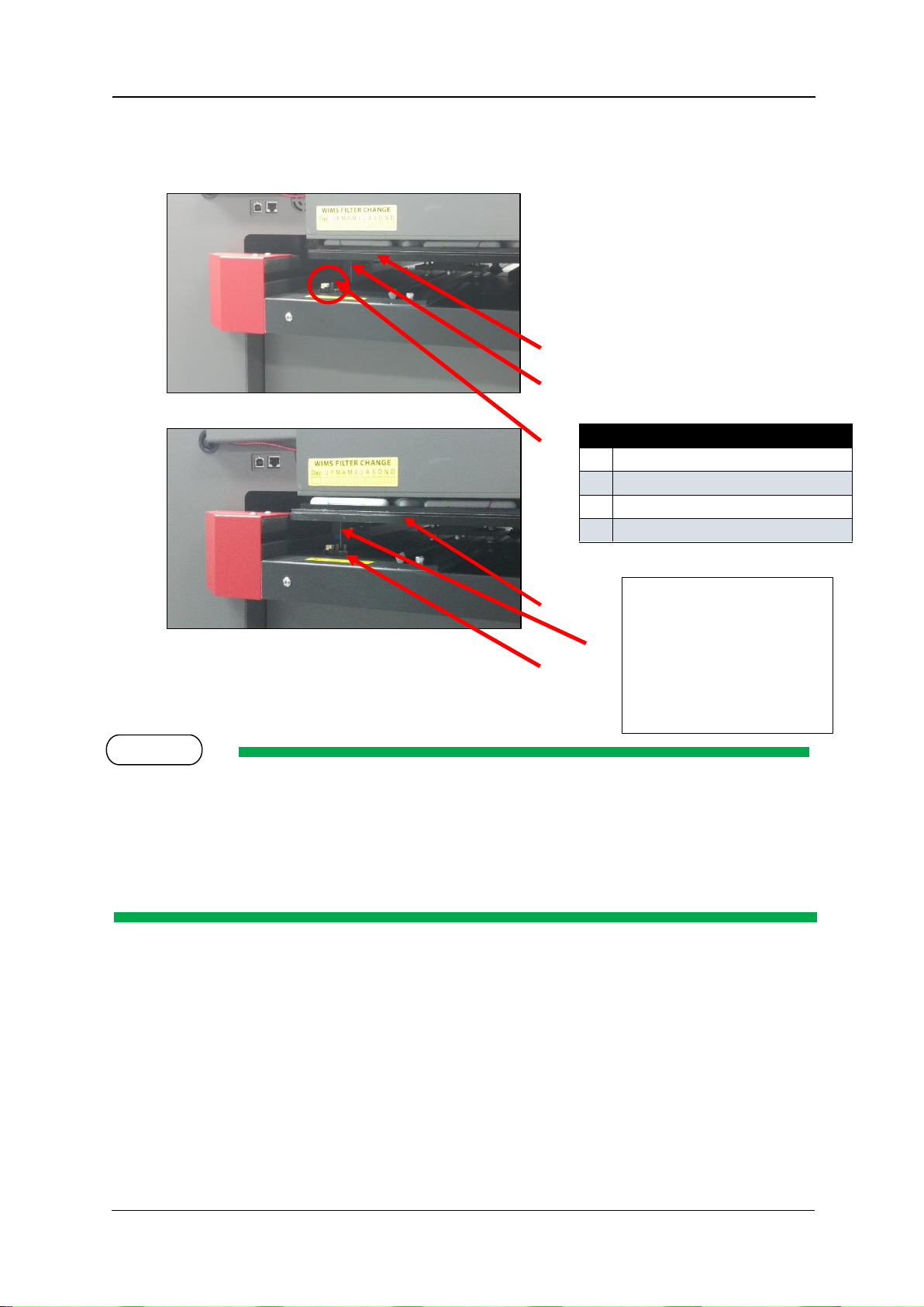
Initial Setup & Basic Operations Compress iUV600s Series User Guide
No. Part name
2 Media Tray
3
Interrupter
4
Media Sensor
2
3
3 2 4
4
NOTE
1
The interrupter is
repositionable in order to
set bed/media 0/0 point
Consult your
representative for further
instructions
6. From the rear of the printer, slowly pull the Media Tray towards the rear of the printer, until
the Media Sensor is triggered by the interrupter located on the base of the Media Tray as
shown here:
The iUV600XL series of printer requires a different loading procedure, as it does not have a
rearMedia Sensor as depicted above for the iUV600s series of printer:
From the rear of the printer, slowly pull the Media Tray towards the rear of the printer, until the front
of the Media Tray clears the Media Switch (which is located on the left hand side of the printer bed,
beneath the printer carriage area). Then, from the front of the printer, pull the Media Tray back over
the Media Switch, by approximately 50mm (2 inches).
7. Press the LOAD button to set the printer to “load mode”. The Load/Eject status light should
turn green.
8. Follow the menu selection described above in Section 2.6.8.2"Accessing the Bi-D Adjustment
Menu" p.59 to access the Bi-D Hi VSD4d utility.
67
Page 76

Compress iUV600s Series User Guide Initial Setup & Basic Operations
FIGURE 3 – DESIRED
ALIGNMENT
9. When Ad j : B i D Hi V S D 4 d is displayed, press the [Enter] key.
10. S e tu p /P r i n t 1 /P r in t 2 will be displayed.
11. Use the following menu flow chart to navigate to P ri n t 1 , press the [Enter] key.
12. A d ju s t m e n t P r i n t i n g will display on the LCD screen, and the test pattern will be printed.
13. The platen will not eject after the test print has completed, so manually pull the platen out
to the front of the printer far enough that you can examine the test print pattern.
The objective is to have the centre vertical bar of the pattern marked “A” to
align with the top and bottom shorter vertical bars. This is accomplished by
applying an offset value (via the screen / keypad) to compensate for the
difference between the printed position and the desired position:
68
Page 77

Initial Setup & Basic Operations Compress iUV600s Series User Guide
NOTE
14. After the test pattern has printed, BiD Hi VSDxx:Setup should display on screen – if it does not,
navigate the control panel / screen until it does (refer toFigure 3-11 Adjustment Menu Flow
page 62). Press the [Enter] key to display the current offset position, and to be able to adjust
it. The figures shown here are examples only, the offset values shown for each printer will
differ:
15. Press ENTER to set the new offset value.
To shift the centre vertical bar in a left direction (as per Figure 3 –
Desired Alignment, above), decrease the offset value. In the example
above, the value of -22 might be decreased to -30 initially. To shift
the centre vertical bar to the right, increase the offset value.
16. Repeat the process of Printing the Bi-D Adjustment Pattern and Effecting the Bi-D Adjustment
until the desired alignment is achieved. This can take many, many iterations.
The printer will
automatically align the
successive prints
correctly progressively
down the page.
69
Page 78

Compress iUV600s Series User Guide Initial Setup & Basic Operations
NOTE
When the page is filled with adjustment patterns, it will be necessary to load a new sheet of paper.
To indicate to the printer that new media is loaded, firstly press the EJECT button (the Load / Eject
LED should show red). Manually pull the platen to the rear of the printer so that the rear media
sensor interrupter is in line with the rear media sensor, press the LOAD button (the LED should show
green).
17. Repeat the entire process for each of the adjustment options for Adj: BiD Hi VSD4d, Adj: BiD
Hi VSD4, and Adj: BiD Hi VSD6
70
Page 79

Initial Setup & Basic Operations Compress iUV600s Series User Guide
NOTE
2.6.9 Installing & Using Printer Drivers
A printer driver is a piece of software that converts the data to be printed to the form specific to a
printer, and it is usually supplied with a new printing device.
In the case of the Compress iUV600s, you will have been supplied with a RIP software which also
converts the data from an image that you wish to print into a form that the printer will understand. In
most cases you will not have need to use the native driver for the printer as the RIP will handle the
printing process.
There may, however, be occasions where you have need to by-pass the RIP software for test printing
purposes. The Driver installation instructions are provided here for that purpose.
2.6.9.1 Setting the IP address in the Printer
If you are installing the printer driver for network connection, then it is necessary that you set the
network (IP) address in the printer before you install the printer driver.
Be sure to set the IP address after consulting the network administrator.
Allocate the IP addresses that do not overlap the computers or routers within LAN (Local Area
Network).
Allocate the same network address (usually the 3rd segment of IP address) as the computer
that is connected to the printer.
If you are using the printer in the network environment where IP addresses are automatically
acquired, prepare an IP address for the printer outside of the address range for DHCP.
1. Check that the printer is turned ON, and is in a Print Ready state Section 2.5.1 "Switching
the Printer ON" p.32
2. Press the [Menu] key on the Operation panel to change the display to the Setting menu.
* M e n u * T e s t P r i n t > is displayed on the Operation panel
3. Press the [Back] or [Next] keys on the Operation panel to display the Network menu
* M e n u * N e t w o r k > is displayed on the Operation panel
71
Page 80

Compress iUV600s Series User Guide Initial Setup & Basic Operations
NOTE
4. Press the [Enter] key on the Operation panel to display the IP address menu.
N e t w o r k : I P A d d r e s s > is displayed on the Operation panel
5. Press the [Enter] key on the Operation panel to display the IP address setting menu
1 9 2 . 1 6 8 . 1 . 2 53 (default) is displayed on the Operation panel
6. Press the following keys on the Operation panel to set the value
\[Forward] key: decreases the setting value
[Reverse] key: increases the setting value
[Enter] key: changes the setting value for the next segment (the IP Address comprises
4 segments, use the [Enter] key to move between segments)
2.6.9.2 Installing the Printer Driver (for network connection)
1. The printer should be connected to the network before installing the printer driver
2.5.3.1 "Connecting Ethernet (network) interface cable" p.35
2. Ensure that the IP address has already been set to the printer 2.6.9.1 “Setting the IP
address in the Printer” p. 68
3. Switch the printer on in accordance with the instructions in Section 2.5.1 "Switching the
Printer ON" p.32
4. Turn on your PC.
Ensure that the PC user account being used to install the printer driver has administrator authority.
5. Ensure that your PC boots up correctly, then insert the printer driver CD into the CD drive on
your PC.
The installer should start.
72
Page 81

Initial Setup & Basic Operations Compress iUV600s Series User Guide
Depending you’re your PC settings, the installer may not automatically start. If the installation does
not automatically start, browse the CD to the driver folder, and then to the appropriate language
folder, and execute “Setup.exe” from the CD.
6. If necessary, allow the necessary actions from any User Account Control dialog box:
7. Select the model (RJ-901X), and click “Install”
If you click “Cancel”, the printer driver installation will be cancelled
The display will move to the next screen
73
Page 82

Compress iUV600s Series User Guide Initial Setup & Basic Operations
8. Click the “installation of a driver” check box and click “Next”.
The display will move to the next screen
9. The license agreement for the driver software will display.
a. If you agree to the written contents, click “Agree”
The display will move to the next screen
b. If you do not agree to the written contents, click “Cancel”
The installation of the driver will be cancelled
The display will move to the next screen
74
Page 83

Initial Setup & Basic Operations Compress iUV600s Series User Guide
DTG M2X
10. Click “Network”
a. If this is the first installation of the printer driver on your PC, proceed to step 11
b. If the printer driver has previously been installed, proceed to step 10
11. Make settings in the dialog box for the following items, and then click “OK”
a. Port name: Enter an arbitrary name
b. IP Address: Enter the IP address set for the printer – for example: 192.168.1.1
For the IP address that is set for the printer, refer to Section 2.6.9.1 Setting the IP address in the Printer”
p. 68
Proceed to step 13
75
Page 84

Compress iUV600s Series User Guide Initial Setup & Basic Operations
12. The output ports that were installed in the past are displayed on the output port list.
a. To use an output port that was installed in the past, select it from the output port list, and
then click “OK”.
Proceed to step 13
b. To add a new port
Click “Add Port”.
76
Page 85

Initial Setup & Basic Operations Compress iUV600s Series User Guide
DTG M2X
Select “MUTOH Network Port”, and then click “New Port”.
Proceed to step 11.
13. Set the printer name, and then click “Next”
If you do not need to change the printer name, use the default name.
The display will move to the next screen
77
Page 86

Compress iUV600s Series User Guide Initial Setup & Basic Operations
DTG M2X
DTG M2X
14. Check the details displayed on screen, and click Next
The driver installation will begin.
15. During the driver installation, a Windows security warning may be displayed. If necessary, click
“Install”.
16. Once the printer driver has been installed, the following screen is displayed.Click “Finish”.
This completes the installation of the printer driver.
78
Page 87

Initial Setup & Basic Operations Compress iUV600s Series User Guide
If you click “Menu”, the first screen of the installer is displayed.
2.6.9.3 Installing the Printer Driver (for USB connection)
1. Turn the printer OFF 2.5.2 “Switching the Printer OFF.p.34
Do not connect the USB Cable yet.
If you have connected the USB cable (with the printer turned on) before installing the
printer driver, refer to Section 2.6.9.4 “If you have connected using the USB cable before
installing the driver” p.82
2. Turn on your PC.
3. Ensure that your PC boots up correctly, then insert the printer driver CD into the CD drive on
your PC.
The installer should start.
Depending you’re your PC settings, the installer may not automatically start. If the installation does
not automatically start, browse the CD to the driver folder, and then to the appropriate language
folder, and execute “Setup.exe” from the CD.
4. If necessary, allow the necessary actions from any User Account Control dialog box:
79
Page 88

Compress iUV600s Series User Guide Initial Setup & Basic Operations
5. Select the model (RJ-901X), and click “Install”
If you click “Cancel”, the printer driver installation will be cancelled
The display will move to the next screen
Click the “installation of a driver” check box and click “Next”.
The display will move to the next screen
6. The license agreement for the driver software will display.
c. If you agree to the written contents, click “Agree”
The display will move to the next screen
80
Page 89

Initial Setup & Basic Operations Compress iUV600s Series User Guide
d. If you do not agree to the written contents, click “Cancel”
The installation of the driver will be cancelled
The display will move to the next screen
7. Click “USB”
The display will move to the next screen
81
Page 90

Compress iUV600s Series User Guide Initial Setup & Basic Operations
8. Driver and port to be installed will be displayed on screen – Check the displayed content, and if
there is no problem, click “Next”
9. If the Windows security warning is displayed during the installation, click “Install”.
10. At this stage, the installer is waiting for the printer to be connected to the computer by USB
cable.
a. Wait until the standby dialog is displayed.
b. Turn the printer ON
c. Connect the printer and computer with a USB cable.
82
Page 91

Initial Setup & Basic Operations Compress iUV600s Series User Guide
NOTE
If you have connected the USB cable before installing the printer driver, refer to Section
2.6.9.4 “If you have connected using the USB cable before installing the driver” p.82
If the printer has not been fully prepared, click “Connect later”
The driver installation will begin.
Once the driver has been installed to Windows, the USB connection dialog will
automatically close.
11. If you are using Windows XP, Found New Hardware Wizard may be displayed.
a. Select “No, not this time” and then click “Next”.
b. Select “install the software automatically”, and then click “Next”.
Once the printer driver has been installed, the following screen is displayed.
83
Page 92

Compress iUV600s Series User Guide Initial Setup & Basic Operations
NOTE
12. Click “End”.
This completes the printer driver installation.
If you click “menu” the first screen of the installer is displayed.
If the printer was not connected during the installation, connect it after this.
84
Page 93

Initial Setup & Basic Operations Compress iUV600s Series User Guide
2.6.9.4 If you have connected using the USB cable before installing the driver
1. For Windows 7
1. Complete steps 3 to 10 of Section 2.6.9.3 Installing the Printer Driver (for USB connection) p.
76.
Select “Connect it later” in step 10 of Section 2.6.9.3 Installing the Printer Driver (for USB
connection) p. 76.
2. Connect the USB cable
3. Turn the printer ON.
4. Devices and Printers (from Control Panel) should display (if it does not, start it manually).
5. Right-click “RJ-901X” which is displayed as an unspecified device and select “Trouble shooting”.
The computer should attempt to detect the problem, and then will display a solution.
85
Page 94

Compress iUV600s Series User Guide Initial Setup & Basic Operations
6. Select “Apply this correction”.
7. Check that the problem is solved, and then finish troubleshooting.
86
Page 95

Initial Setup & Basic Operations Compress iUV600s Series User Guide
2. For Windows 7
1. Open “Devices and Printers” from Control Panel on your PC.
2. Select “RJ-901X” which is displayed as an unspecified device and click “Remove device”.
3. Turn the printer OFF
4. Remove the USB cable.
5. Follow the procedure from step 3 of Section 2.6.9.3 Installing the Printer Driver (for USB
connection) p. 76 to start installation.
87
Page 96

Compress iUV600s Series User Guide Printing to substrates
3. Printing to Rigid Substrates
88
Page 97

Printing to Substrates Compress iUV600s Series User Guide
3.1 Introduction
Printing on various items with the Compress iUV600s™ is a very simple process involving five easy
steps:
1. Create an image in any of your graphics programs
2. Prepare a substrate or item for printing
3. Prepare the substrate and load the substrate or item onto the printer
4. Set-up your image for printing with the RIP program
5. Press the Print button.
Once you are comfortable with the basic operations of your Compress iUV600s™, you are ready to
proceed!
3.2 Prepare Your Image
Your product will only ever be as good as the artwork from which it is printed, regardless of the RIP
that is used to send the printing information to the printer. It is essential that you have a basic
understanding of image or graphic types in order to understand your artwork:
(1) Vectors
Vector graphics are made up of mathematical outlines and curves
that make the shapes in the image. They are commonly referred to
as Vectors. Adobe Illustrator and Corel Draw are two programs that
create Vector images. These programs have tools that allow the
artist to create outlines of any shape they wish. Once an outline is
connected or closed the shape can be filled with any color or
texture generated by the software. Since these shapes are
created by computer generated outlines the resolution is
infinite. That is, you can enlarge the image as much as you
want and because the image is made up of
mathematical shapes & curves, these shapes
and curves will enlarge infinitely without
losing resolution, as will any “fill” to
those shapes or curves.
The file format for Adobe Illustrator is
(.ai) and for Corel Draw is (.cdr).
89
Page 98

Compress iUV600s Series User Guide Printing to substrates
(2) Bitmaps
Bitmaps are images made up of pixels. This is a grid of small
squares of appropriate colours that when viewed at a distance
make a graphic image such as a digital photograph or digital art.
Bitmaps are technically known as Raster Images. Since these
images are made up of a finite number of bits generated at the
time of the creation of the image, there are limits as to how
much you can enlarge the image. Imagine a small solid red
square, say 1 inch x 1 inch.
This square was digitally created at 300dpi, meaning (in the
simplest terms) there are actually 300 red dots making up
the red square. If you now want to enlarge
that red square to 2 inches x 2 inches, it is
possible, however you still only have 300
red dots to fill that square.
The most common file formats for Raster
Images are Bitmaps (.bmp), Jpegs (.jpg),
Tiffs (.tif), and Gifs (.gif).
(3) Resolution
Because a Raster or bitmap is made up of little square dots of colour, the images can often have a
jagged look. The greater the number of pixel dots per inch the less jagged the image will look. It will
also increase the data size of the file considerably. Dots per inch or DPI is the measurement of the
pixel density. One example of low DPI images are web graphics. Web graphics are low to minimize
the amount of data bites it takes to load a web page. Web graphics are usually 72dpi or 96dpi. In
printing on fabric, it is best to use a DPI of at least 200dpi, preferably 300dpi or greater – at the
printing size.
Programs such as Photoshop can be used to “upsample” a small, low resolution image to an image of
suitable size & resolution, however you must be aware that these programs will make assumptions &
calculations as to where to place the extra pixels & what colour to make them. Images that have
been upsampled in this way will often have softer edges, but will be less pixilated. Unless you are
proficient in graphics programs, it is always best to ask your client for a higher resolution file in the
first place.
Also ensure that there is not excessive “blank” space around the edges of the image – even blank
space counts towards image size and may cause the actual “picture” to print small in order to fit the
en tire image on to the platen. Trim unnecessary blank space from the top, bottom & sides of the
image.
90
Page 99

Printing to Substrates Compress iUV600s Series User Guide
(4) Image Sharpness & Saturation
Images printed to fabric often tend to be softer & darker than what the image appears on screen.
You may need to adjust images to give them a colour boost using a saturation adjustment in the
graphics program, and/or sharpen the image using suitable sharpening tools within the graphics
program.
(5) Transparent Backgrounds
As we have already discussed, regular bitmap images are made up of coloured pixels; this includes the
background (even a plain white background!). In a digital photograph, the rectangle is filled entirely
with colour. Graphic images are not usually just a rectangle. They are shapes and text. The
background area is usually filled with white pixels. To print on a media other than white, it is almost
impossible to match the digital colour with the colour of the media.
In programs such as Photoshop, the file data includes transparent pixels as a background colour of
choice. If the file is set to have a transparent background, then a removed or erased pixel will be
virtually removed. Transparent backgrounds are often represented by a grey and white checker
board pattern.
WHITE PIXELS IN BACKGROUND TRANSPARENT PIXELS IN BACKGROUND
The standard printer driver was designed to print on a white surface using colour ink. Inherently, it
ignores white pixels in an image when printing, and only prints the colour pixels.
The RIP supplied by your authorized DTG Distributor, however, is designed to print all nontransparent pixels, and particularly, to print white pixels with white ink.
It will separate the image into a white ink “underbase” layer (made up of all pixels in the image) and a
colour layer with very little additional effort on your part.
91
Page 100

Compress iUV600s Series User Guide Printing to substrates
TIP
Example of template file
suitable for printing golf
balls
3.3 Substrate Preparation
LED curable UV ink allows you to print onto the greatest variety of substrates, ink adhesion is
promoted on some substrates by way of applying a primer. Consult your product representative for
available primers, their application and use as well as what alternatives are available. It is assumed
that proper substrate sampling/trialing has been committed to prior to the purchase of your machine
The following information is supplied specifically in relation to Pigmentinc P70i UV –LED inks and
primers Please refer to instructions supplied with alternative primers / inks as the processes and
results will vary.
Glass, most metals, and some plastics require a pre primer process. The primer / underbase forms a
special receptive surface for the UV ink to adhere to. POOR PRIMER = POOR PRINT QUALITY.
Many substrates will not require any form of preparation and can be printed and packed without
additional steps and man handling.
It should be noted that as a manufacturer we have no control over the immense variety of substrates
that end may wish to print onto. Therefore, we suggest that you test all media/substrates and ensure
suitability for UV printing. Ink adhesion should be the main consideration and should be confirmed
prior to accepting commercial print orders.
It should also be noted that for printing onto irregular shaped object, for example promotional items,
that an accurate template should be made to ensure that the placement of the object in relationship
to the graphic file match perfectly.
Safety
Please refer to the supplied MSDS sheet prior to the safe use of any ink chemical products.
92
 Loading...