

Page 1

USER MANUAL
Model:
CSW-VGA211,
Automatic VGA / Audio Switcher
For maximum results, use Comprehensive
Brand Premium High Resolution cables
and connectors.
Page 2

Contents
1
Introduction 1
2
Getting Started 1
3
Overview 1
4
Your CSW-VGA211 Automatic VGA / Audio Switcher 2
5
Using the CSW-VGA211 Automatic VGA / Audio Switcher 4
5.1 Connecting the CSW-VGA211 Automatic VGA / Audio Switcher 4
5.2 Selecting the Default VGA Master Source Signal 6
5.3 Connecting the REMOTE Connector 7
5.3.1 Connecting the REMOTE Connector when IN 2 is the DEFAULT 8
6
Technical Specifications 9
Figures
Figure 1: CSW-VGA211 Automatic VGA / Audio Switcher Topside 2
Figure 2: CSW-VGA211 Automatic VGA / Audio Switcher Underside 3
Figure 3: CSW-VGA211 Automatic VGA / Audio Switcher Connections 5
Figure 4: Remote Terminal Block Connector 7
Figure 5: Connecting the REMOTE Connector when IN 1 is the DEFAULT 8
Figure 6: Connecting the REMOTE Connector when IN 2 is the DEFAULT 8
Tables
Table 1: CSW-VGA211 Automatic VGA / Audio Switcher Features 3
Table 2: CSW-VGA211 Automatic VGA / Audio Switcher Underside Features 3
Table 3: CSW-VGA211 Automatic VGA / Audio Switcher Technical Specifications 9
i
Page 3

1 Introduction
Congratulations on purchasing your CSW-VGA211 Automatic VGA / Audio
Switcher, which is ideal for:
Automatic computer and presentation VGA / XGA routing
Presentation systems with wall plates
The package includes the following items:
CSW-VGA211 Automatic VGA / Audio Switcher
Power adapter (12V DC input) and this user manual
2 Getting Started
We recommend that you:
Unpack the equipment carefully and save the original box and packaging
materials for possible future shipment
Review the contents of this user manual
3 Overview
Your CSW-VGA211 is a high performance 2x1 automatic switcher for
VGA/SVGA/XGA/UXGA and stereo audio signals. The CSW-VGA211
detects the presence of the active VGA-type input signal from either IN 1 (the
default1) or IN 2—depending on how both DEFAULT SELECT switches2 are
set, as section 5.2 describes—and automatically routes it to the acceptor
connected to the VGA OUT and the AUDIO OUT connectors. In addition,
the CSW-VGA211:
With its video bandwidth exceeding 400MHz, ensures transparent
operation at the highest resolutions
Automatically switches the stereo audio signal with the video signal
(audio-follow-video) when switching the active input to the output
Includes ID BIT control3
Includes a pair of DEFAULT SELECT switches on the underside
for selecting the default VGA master source signal
1 That is, both DEFAULT SELECT switches on the underside are factory preset to IN 1
2 Both DEFAULT SELECT switches MUST be set to the identical IN #
3 Sometimes notebook computers refuse to output a VGA signal to an external VGA monitor. By setting the ID BIT to ON,
the notebook will output to an external VGA monitor
1
Page 4
Includes a looping XGA input with a loop termination switch
Comes with contact closure remote control for forced operation
Uses active switching and has very selective sync detection and
reconstruction circuitry
To achieve the best performance:
Connect only good quality connection cables, thus avoiding interference,
deterioration in signal quality due to poor matching, and elevated noiselevels (often associated with low quality cables)
Avoid interference from neighboring electrical appliances and position your
machine away from moisture, excessive sunlight and dust
Caution – No operator-serviceable parts inside unit.
Warning – Use only the input power wall adapter that is
provided with this unit.
Warning – Disconnect power and unplug unit from wall
before installing or removing device or servicing unit.
4 Your CSW-VGA211 Automatic VGA / Audio Switcher
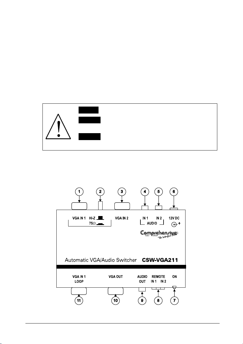
Figure 1 and Table 1 define the topside of the CSW-VGA211 Automatic
VGA / Audio Switcher:
Figure 1: CSW-VGA211 Automatic VGA / Audio Switcher Topside
2
Page 5

Table 1: CSW-VGA211 Automatic VGA / Audio Switcher Features
# Feature Function
1 VGA IN 1 HD15F Connector Connects to the video source 1
2
Hi-Z / 75 Loop Termination Switch Release to select Hi-Z; push in to terminate VGA IN 1 with 75
3 VGA IN 2 HD15F Connector Connects to the video source 2
4 AUDIO IN 1 mini plug Connector Connects to audio source 1
5 AUDIO IN 2 mini plug Connector Connects to audio source 2
6 12V DC +12V DC connector for powering the unit
7 ON LED Illuminates when receiving power
8 REMOTE IN 1 and IN 2 Terminal
Block Connectors
9 AUDIO OUT mini plug Connector Connects to the audio acceptor
10 VGA OUT HD15F Connector Connects to the video acceptor
11 VGA IN 1 LOOP HD15F Connector Connects to an additional monitor
Connect to a dry contact switch
Figure 2 and Table 2 define the underside of the CSW-VGA211:
Figure 2: CSW-VGA211 Automatic VGA / Audio Switcher Underside
Table 2: CSW-VGA211 Automatic VGA / Audio Switcher Underside Features
# Feature Function
1 Pair of DEFAULT SELECT Switches Set both switches to IN 1 to select input signal 1, as default; or
2 ID BIT Switch Slide to the left to set to ON1; to the right to set to OFF
to IN 2, to select input signal 2 as default (see section 5.2)
1 Enabling the notebook to output a VGA signal to an external VGA monitor
3
Page 6

5 Using the CSW-VGA211 Automatic VGA / Audio Switcher
This section describes:
Connecting the CSW-VGA211 (see section 5.1)
Selecting the default master source signal (see section 5.2)
Connecting the REMOTE connector (see section 5.3)
5.1 Connecting the CSW-VGA211 Automatic VGA / Audio Switcher
To connect your CSW-VGA211, connect the 2 VGA INPUTS, with VGA
INPUT IN 1 set as the active master source signal, as the example in Figure 3
illustrates:
1. Connect a VGA/Audio source (for example, a PC (Master Source)) to the
VGA IN 1 HD15F connector and to the AUDIO IN 1 mini plug connector.
Both underside DEFAULT SELECT switches should be set to IN 1 (the
factory preset default), as section 5.2 describes.
2. Connect a second VGA/Audio source (for example, another PC) to the
VGA IN 2 HD15F connector and to the AUDIO IN 2 mini plug connector.
3. Connect the VGA OUT HD15F connector and the AUDIO OUT mini plug
connector to the acceptor (for example, a video monitor with speakers).
4. Connect (optional) an additional monitor to the VGA IN 1 LOOP HD15F
connector and release the loop termination switch to select Hi-Z. Select 75
on the loop termination switch if the VGA IN 1 LOOP is not connected.
5. Connect the 12V DC power adapter to the power socket and connect the
adapter to the mains electricity.
4
Page 7

Figure 3: CSW-VGA211 Automatic VGA / Audio Switcher Connections
5
Page 8

5.2 Selecting the Default VGA Master Source Signal
Both DEFAULT SELECT switches are factory preset to IN 1 and the
CSW-VGA211 will detect the presence of the master source signal at the
VGA IN 1 connector. If you connect active sources to both the VGA IN 1 and
the VGA IN 2 connectors, the source at the VGA IN 1 connector takes
priority over the source at the VGA IN 2 connector and it is routed it to the
VGA OUT and the AUDIO OUT connectors (audio follows the video).
You can change the default so that the CSW-VGA211 automatically detects
an active source signal from VGA IN 2, by setting the pair of DEFAULT
SELECT switches1 to IN 2. When active, the source at the VGA IN 2
connector takes priority over the source at the VGA IN 1 connector and it is
routed to the VGA OUT and the AUDIO OUT connectors (audio follows the
video).
If the CSW-VGA211 detects:
No signal2 at the VGA IN 1 input (when IN 1 is selected as the
default), the CSW-VGA211 routes the signal from the source at VGA IN
2 to the VGA OUT and the AUDIO OUT connectors. Similarly, if the
CSW-VGA211 detects no signal at the VGA IN 2 input (when IN 2 is
selected as the default), the CSW-VGA211 routes the signal from the
source at VGA IN 1 to the VGA OUT and the AUDIO OUT connectors
A signal from the VGA source at VGA IN 1 input (when IN 1 is
selected as the default), while routing the signal from the VGA source at
VGA IN 2, the CSW-VGA211 will reroute the signal from the VGA
source at VGA IN 1 to the VGA OUT and the AUDIO OUT connectors.
Similarly, if the CSW-VGA211 detects a signal from the VGA source at
VGA IN 2 input (when IN 2 is selected as the default), while routing the
signal from the VGA source at VGA IN 1, the CSW-VGA211 will
reroute the signal from the VGA source at VGA IN 2 to the VGA OUT
and the AUDIO OUT connectors
No signal at all (that is, when there is no active input from a source
at VGA IN 1 or at VGA IN 2), the CSW-VGA211 will still route VGA
IN 2 to the VGA OUT, and continue to examine VGA IN 1 input (when
IN 1 is selected as the default), switching back to it when it detects a
valid signal. Similarly, if the CSW-VGA211 detects no signal at all
(when IN 2 is selected as the default), it will still route VGA IN 1 to the
VGA OUT, and continue to examine VGA IN 2 input, switching back to
it when it detects a valid signal
1 Both DEFAULT SELECT switches MUST be set to the identical IN #
2 Perhaps no source is connected, or that source is connected but its power is OFF
6
Page 9

5.3 Connecting the REMOTE Connector
You can force the routing of one of the 2 inputs to the VGA output by remote
control. To do so, connect the appropriate REMOTE input terminal block
connector pins to a dry contact switch1. For example, as Figure 4 illustrates, to
route REMOTE IN 1 to the VGA output, connect PIN 3 to PIN 2. To route
REMOTE IN 2 to the VGA output, connect PIN 1 to PIN 2. Do not connect both
the REMOTE IN 1 and the REMOTE IN 2 to PIN 2 simultaneously.
Route input 1 to the output,
by attaching PIN 3 to PIN 2:
Route input 2 to the output,
by attaching PIN 1 to PIN 2:
Figure 4: Remote Terminal Block Connector
When both VGA IN 1 and VGA IN 2 are connected, the signal from VGA IN
1 routes to the output. However, you can force the routing of VGA IN 2 to the
output by attaching PIN 1 to PIN 2. If no input is present on VGA IN 1, you
can even force the routing of the output from VGA IN 1 (displaying a blank
screen) by attaching PIN 3 to PIN 2.
1 Note that the connection should be permanent, since the CSW-VGA211 will revert to an automatic switcher when the
connection is removed
7
Page 10

5.3.1 Connecting the REMOTE Connector when IN 2 is the DEFAULT
By default1 the CSW-VGA211 automatically detects an active source signal
from VGA IN 1, and the order of the REMOTE input connectors is as printed:
Figure 5: Connecting the REMOTE Connector when IN 1 is the DEFAULT
If you change the default2 so that the CSW-VGA211 automatically detects an
active source signal from VGA IN 2, the order of the REMOTE input
connectors automatically changes (IN 1 acts as IN 2, and IN 2 acts as IN 1):
Figure 6: Connecting the REMOTE Connector when IN 2 is the DEFAULT
1 The pair of DEFAULT SELECT switches are set to IN 1
2 By setting the pair of DEFAULT SELECT switches to IN 2
8
Page 11

6 Technical Specifications
Table 3 includes the technical specifications:
Table 3: CSW-VGA211 Automatic VGA / Audio Switcher Technical Specifications1
INPUTS: 2 VGA/UXGA on HD15F connectors
OUTPUTS: 1 VGA/UXGA on a HD15F connector
MAX. OUTPUT LEVEL: Video: 1.8 Vpp; Audio: 5Vpp
BANDWIDTH (-3dB): Video: 400 MHz; Audio: 100 kHz
DIFF. GAIN: 0.04%
DIFF. PHASE: 0.03 deg
K-FACTOR: <0.05%
S/N RATIO: Video: 70.6 dB; Audio: 89 dB unweighted
CROSSTALK: Video: -56 dB @ 5 MHz; Audio: -52 dB @ 1kHz
CONTROLS: Input 1 termination switch, contact closure remote control, input 1 ID Bit
COUPLING: DC
AUDIO THD + NOISE: <0.019%
AUDIO 2nd HARMONIC: <0.003%
POWER SOURCE: 12 VDC 50 mA
DIMENSIONS: 12 cm x 7.5 cm x 2.5 cm (4.7" x 2.95" x 0.98", W, D, H)
WEIGHT: 0.3 kg (0.66 lbs.) approx.
ACCESSORIES: Power supply, mounting bracket
2 unbalanced stereo audio on 3.5 mm mini audio connectors
1 VGA/UXGA on a HD15F connector (input #1 loop)
2 unbalanced stereo audio on a 3.5 mm mini audio connector
switch (accessible from the underside or internally)
Input default selection switches accessible from the underside
1 Specifications are subject to change without notice
9
 Loading...