

Page 1
Instruction Manual
CSW-HDMI210 & CSW-HDMI410
HDMI Switchers
Page 2

2
Page 3

Table of Contents
1.0 Introduction 4
2.0 Specifications 5
3.0 Checking Package Contents 6
4.0 Connecting The Hardware 7
5.0 Operating The Unit 7
6.0 Installation of Mounting Components 8
7.0 Troubleshooting 9
8.0 Limited Warranty 9
9.0 Regulatory Compliance 10
10.0 Appendix A: RS-232 Code Information 10
3
Page 4

1.0 INTRODUCTION
Thanks for purchasing this CSW-HDMI210 or CSW-HDMI410 HDMI Switcher
from Comprehensive. These HDMI Switchers are designed to provide a way to
select and switch up to 4 HDMI inputs without signal degradation or loss of
encryption.
1.1 Liability Statement
Every effort has been made to ensure that this product is free of errors.
Comprehensive cannot be held liable for the use of this hardware or any direct or
indirect consequential damages arising from its use. It is the responsibility of the
user of the hardware to check that it is suitable for his/her requirements and that
it is installed correctly. All rights reserved. No parts of this manual may be
reproduced or transmitted by any form or means electronic or mechanical,
including photocopying, recording or by any information storage or retrieval
system without the written consent of the publisher.
Comprehensive reserves the right to revise any of its hardware and software
following its policy to modify and/or improve its products where necessary or
desirable. This statement does not affect the legal rights of the user in any way.
All third party trademarks and copyrights are recognised. The Comprehensive
logo is the registered Trademarks of Comprehensive. All other trademarks are
the property of their respective holders.
1.2 FEATURES
The Comprehensive CSW series of HDMI Switchers have many features that
enable them to perform in a superior manner. Among these features you will find:
• Switches from 2 or 4 HDMI sources
• Supports 480i, 480p, 720p, 1080i and 1080p resolution
• HDMI Certified by Silicon Images ATC Laboratory
• Supports DDWG standard for HDMI compliant monitors
• HDCP Compliant. RoHS Compliant
• IR Remote Control Capability
• RS-232 Control Port Provided
4
Page 5

2.0 SPECIFICATIONS
Performance
HDTV Resolutions 480p, 720p, 1080i, 1080p
Standard TV Resolution 480i
Maximum Cable Distance Input: 50 Feet Max, Outputs: 50 feet Max
I/O Connectors
Inputs
Output
Mechanical
Dimensions (H-W-D)
Weight
Warranty
2, or 4 HDMI TMDS
HDMI, TMDS x1 (All Models)
CSW-HDMI210 1.1”x8.7”x2.8” (28x220x71mm)
CSW-HDMI410 1.1”x8.7”x2.8” (28x220x71mm)
CSW-HDMI210 1.0 lbs (480g)
CSW-HDMI410 1.0 lbs (480g)
Limited Warranty 2 Years Parts and Labor
Environmental
Operating Temperature +0 to +40° C (+32° to 104° F)
Operating Humidity 10% to 85% (Non-condensing)
Storage Temperature -20° to +60° (+20° to +140° F)
Storage Humidity 10% to 85% (Non-condensing)
Remote Control
Serial Interface
Infrared
Warranty
RS-232
IR Remote Included
Limited Warranty 2 Years Parts and Labor
Power Requirements
External Power Supply
Regulatory Approvals
5VDC@2A
Distribution Amplifier FCC, CE, RoHS, HDMI ATC
Power Supplies UL, CE, CSA, CEC, RoHS
Accessories Included
1x AC Power Adapter US, UK or Euro Type
1x Remote Control IR Type
1x Instruction Manual
Remote Mtg. Kit CSW-HDMI210, CSW-HDMI410
Product Item Number
CSW-HDMI210 2x1 HDMI Routing Switcher
CSW-HDMI410 4x1 HDMI Routing Switcher
Optional Accessory
1x Extended IR Sensor Remote IR sensor Module
5
Page 6

3.0 CHECKING PACKAGE CONTENTS
Before attempting to use this unit, please check the packaging and make certain
the following items are contained in the shipping carton:
• 1 ea HDMI Switcher
• 1 ea 5 VDC Power Adapter
• 1 ea IR Remote Control
• 1 ea Remote Mounting Kit
• 1 ea Instruction Manual
Note: Please retain the original packing material should the need ever arise to
return the unit. If you find any items are missing, contact your reseller or
Comprehensive immediately. Have the Model Number, Serial Number and
Invoice available for reference when you call.
6
Page 7

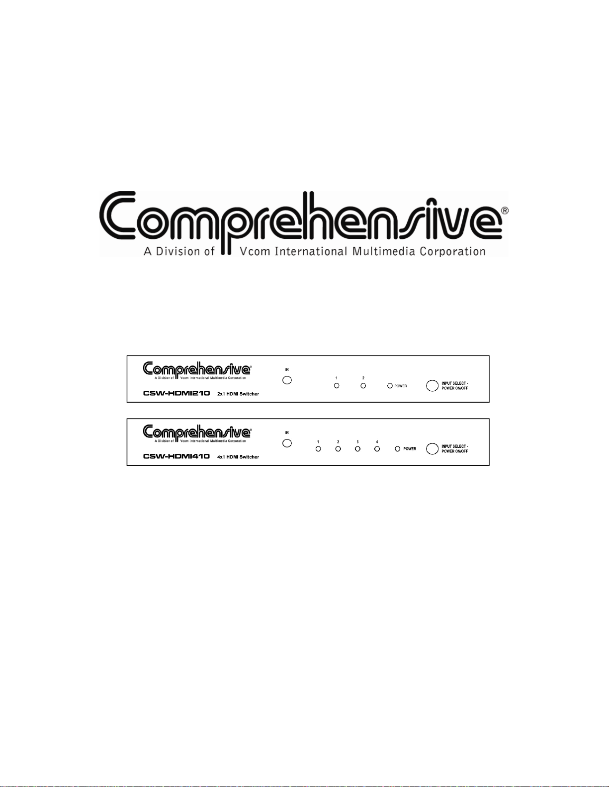
4.0 CONNECTING THE HARDWARE
For reference purposes, the units are depicted below in relative scale. Please
study the drawings below and become familiar with the location of the controls,
status LEDs, signal inputs, signal output and the power input.
Connect an HDMI approved cable, no more than 50 feet in length, from each of
the HDMI sources to the inputs of the switcher. Next, connect the output of the
switcher to the destination device using an HDMI approved cable no more than
50 feet long*. Connect the extended IR remote cable if desired and lastly,
connect the power adapter, first to the switcher and then to the AC source.
*Note: Proper operation of HDMI switchers depend on the use of the highest
quality cables available. A Cable providing low loss, high bandwidth signal
handling is the recommended cable for use with all Comprehensive HDMI
products. The distance specification of 50 feet is for HDMI signals up to 1080i
resolution but cannot be guaranteed unless highest quality cables are used
throughout the system.
5.0 OPERATING THE UNIT
Power and input selection are controlled from one multi-purpose switch. To turn
the switcher on, press the Input Select – Power On/Off
the operating state, pressing the switch causes the input selection to advance
each time it is pressed. (An LED will light to show which input is active.) Once the
highest input number is reached, pressing the switch again will select input
number 1. Pressing and holding the switch for two (2) seconds will cause the
unit to power off. For greater flexibility, an Infrared remote control is also
switch. Once the unit is in
7
Page 8

provided. In the case of the remote, there are separate buttons for the power and
input sources. Point the remote control at the unit and press the power button to
turn the switcher on or off. Press the appropriate input select button to cause the
desired input to appear on the switcher’s output.
5.1 OPERATION USING THE OPTIONAL EXTENDED IR MODULE
An optional IR extender accessory is available for those situations requiring the
switcher to be mounted in a location where direct line-of-sight is not available. If
you have purchased the optional IR extension module, connect it to the rear of
the unit and position the module in a manner that allows the furnished remote to
be pointed at it without any obstructions between the remote and the extended IR
module. The Module is shipped with a 6 foot interconnect cable. Longer length
cables are available up to 50 Feet.
Operation using the extended IR module accessory is the same as with the
standard IR remote capability.
6.0 INSTALLATION OF MOUNTING COMPONENTS
The CSW-HDMI210 and CSW-HDMI410 switchers can be mounted on any flat
surface.
Mounting the CSW-HDMI210 or CSW-HDMI410 Switchers
Attach the two “L” shaped mounting brackets to the product using the furnished
hardware and then attach the combined assembly to the desired location.
Note that the holes on the brackets are offset to allow easier mounting to the flat
surface after you’ve attached the brackets to the switcher.
Top View
Front View
8
Page 9

7.0 TROUBLESHOOTING
In the event of problems, first make certain that the input and output cables are
no more than 50 feet long (for signals to 1080i resolution) and are of the highest
possible quality. Next, make certain that the Switcher is receiving power.
If all is well in these areas, remember that HDMI devices communicate with one
another so the source devices and destination device must be fully HDMI
capable. In addition, HDCP encryption requires additional processing which also
is dependent on the equipment you have connected to the sources and
destination device. If you experience problems using the HDMI Switcher, you
should attempt to determine what is wrong by attaching each of the source
devices – one at a time – directly to the destination device using the same cables
you are using with the expanded system. This is a way of determining if the
problem is due to bad cables or a problem with the other devices. If you are
unable to obtain a signal using this simplified path, suspect the cables, the
source device(s) or the destination device.
After trying the above suggestions should the problem persist, contact your
dealer for additional suggestions before contacting Comprehensive. Should the
dealer’s technical personnel be unable to assist you, contact Comprehensive at
800-526-0242 or via Fax at 201-814-0510.
8.0 LIMITED WARRANTY
Comprehensive warrants that for a period of 2 years from date of original
purchase, our products will be free from defects in material and workmanship
under normal use and service. This warranty covers defective material or
workmanship only and does not apply to misuse, use under extreme conditions,
products that have been opened or serviced by anyone other than
Comprehensive, products improperly used or installed, fire, flood damage or any
acts of nature.
A Return Authorization (RA) number must be obtained from your place of
purchase before the unit is returned and must be accompanied by a dated written
proof of purchase. All material must be shipped at the expense and risk of the
owner. Units under warranty deemed to be defective will be shipped back to the
buyer or dealer freight paid. Contact Comprehensive customer service at 800526-0242, or customerservice@comprehensiveinc.com.
Comprehensive’s obligation under this warranty will be limited, at the sole
discretion of Comprehensive, to either repair or replacement of defective unit,
including free parts and labor. In no event shall Comprehensive be responsible
for any incidental or consequential damages or loss of profits or goodwill.
9
Page 10

9.0 REGULATORY COMPLIANCE
The Comprehensive CSW series HDMI Switchers have been tested for
compliance with appropriate FCC and CE rules and regulations and are also
RoHS compliant.
The Power Adaptor/Supplies have been tested for compliance with UL, CE, CEC
and CSA rules and regulations and are also RoHS compliant.
10.0 APPENDIX A: RS-232 CODE INFORMATION
Transmission Format:
Baud Rate: 57600 BPS
Data Byte: 8 bits
Parity: None
Stop Bit: 1
Modem Cable Pinouts:
Switcher End Controller End
Pin Definition Pin Definition
1 NC 1 NC
3 TxD
2 RxD 3 TxD
4 NC 4 NC
5 GND 5 GND
6 NC 6 NC
7 NC 7 NC
8 NC 8 NC
9 NC 9 NC
2X1 Commands:
Command Code Description
0x01 Port 1 On
0x02 Port 2 On
0x05 Power On/Off
2 RxD
10
Page 11

4X1 Commands:
Command Code Description
0x01 Port 1 On
0x02 Port 2 On
0x03 Port 3 On
0x04 Port 4 On
0x05 Power On/Off
11
Page 12

Comprehensive
55 Ruta Court
South Hackensack, NJ 07606
Phone: 800-526-0242
Fax: 201-814-0510
 Loading...