

Page 1

HDMI Matrix Switchers CSW-HD1616
User Manual
Please read this manual car ef ul l y before using this product.
Page 2

HDMI Matrix Switcher
ii
SAFETY PRECAUTIONS
Please read all instructions before attempting to unpack, install or operate this equipment
and before connecting the power supply.
Please keep the following in mind as you unpack and install this equipment:
• Always follow basic safety precaution to reduce the risk of fire, electrical shock and injury
to persons.
• To prevent fire or shock hazard, do not expose the unit to rain, moisture or install this
product near water.
• Never spill liquid of any kind on or into this product.
• Never push an object of any ki n d i n to this product t hrough any openings or empty slots in
the unit, as you may damage parts inside the unit.
• Do not attach the power supply cabling to building surfaces.
• Use only the supplied power supply unit (PSU). Do not use the PSU if it is damaged.
• Do not allow anything to rest on the power cabling or allow any weight to be placed upon
it or any person walk on it.
• To protect the unit from overheating, do not block any vents or openings in the unit
housing that provide ventilation and allow for sufficient space for air circulate around the
unit.
Page 3

HDMI Matrix Switcher
iii
Contents
1. Introduction ............................................................................................................................. 1
1.1 About HDMI Matrix Switcher System ......................................................................................... 1
HDMI Matrix Switcher Mod els ....................................................... Error! Bookmark not defined.
1.2
2. MHD Packing of the Product ............................................................................................... 2
3. MHD Installation ..................................................................................................................... 2
4. Front View and Rear View of the Product ........................................................................ 3
4.1 Front view of CSW-HD1616 ........................................................................................................... 3
Rear view of CSW-HD1616 ............................................................................................................ 3
4.2
5. External Connection .............................................................................................................. 3
5.1 Introduction of the Input and Output Connectors ...................................................................... 3
Connection of RS-232 Communication Port ................................................................................ 3
5.2
5.2.1 Connection with Control Sys tem ......................................................................................................... 3
5.2.2
Connection with Computer ................................................................................................................... 4
5.3 How to Connect with the Input and Output Terminals ............................................................... 4
6. Operation of the EDID management ................................................................................. 5
6.1 EDID automatically shake hand .................................................................................................... 6
EDID management of MHD matrix .............................................................................................. 6
6.2
7. Operation of the Control Panel ........................................................................................... 7
7.1 Front Panel Description ....................................................................................................................... 7
7.2 Command Format of the Switching Operation
8. Usage of the Remote Controller ........................................................................................... 9
9. Communication Protocol and Command Codes ......................................................... 10
10. Specification ...................................................................................................................... 13
11. Troubleshooting & Maintenance .................................................................................. 14
................................................................................. 8
Page 4
HDMI Matrix Switcher
1
1. Introduction
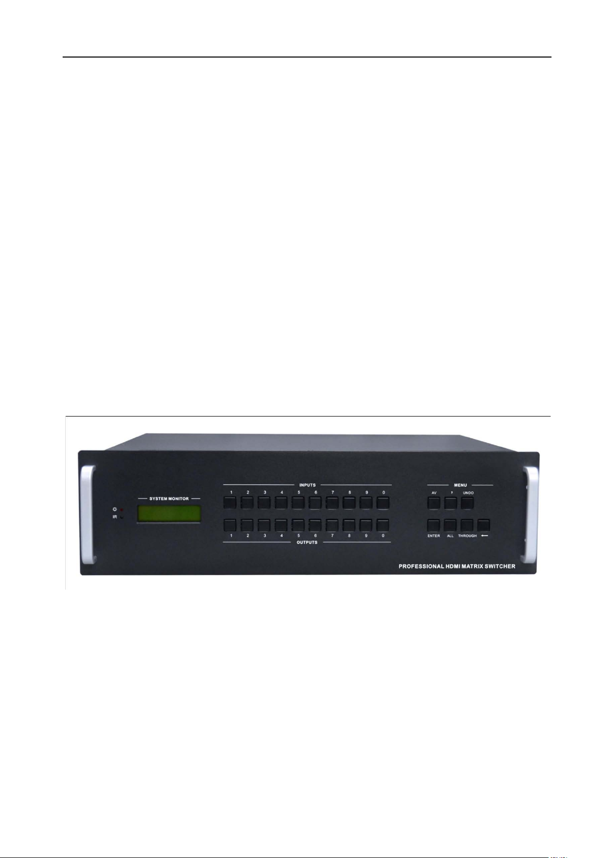
1.1 About HDMI Matrix Switcher CSW-HD1616
CSW-HD1616 is a high-performance digital signal switcher t hat ca n be used for cross switching
of multi computer and audio si gnal. Independent HDMI component and I/O terminals make each
component signal transm it and switch separately; this design can reduce attenuation of sign al
transmission to minimum and out put the image and audio signal in hig h-fidelity quality.
CSW-HD1616 mostly apply in broadcasting TV engi neer ing, multi-media meeting room, big
screen display engineeri ng, television education, comm and control center and other fields. With
RS232 interface, it can be w or ked with PC, remote control syste m and a ny other far-end control
system devices.
2. CSW-HD1616
front view
Page 5
HDMI Matrix Switcher
2
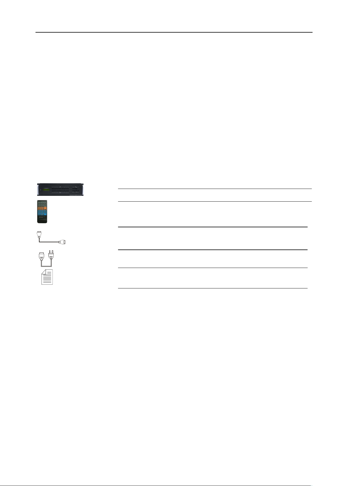
Packing of the Product
HDMI Matrix Switcher
IR remote
RS-232 Communication C ord
Power Supply Cord
User Manual and Quality Guarantee
2. Installation
CSW-HD1616 adopts metal shell and can be stacked with ot her device. Moreover, it is
rack-mountable enclosure and can be instal led in the standard 19 inches rack.
Page 6

HDMI Matrix Switcher
3
3. Front View and Rear View of the Product
4.1 Front view of CSW-HD1616
4.2 Rear view of CSW-HD1616
4. External Connection
5.1 Introduction of the Input and Output Connectors
CSW-HD1616 is made up of 8-channels input/output HDMI ports ( di git al audio included).
5.2 Connection of RS-232 Communication Port
Except the front control panel, the HDMI matrix switcher can be control by far-end contro l system
through the Ethernet contr ol via the RS-232 communication p or t .
5.2.1 Connection wi th Control System
With the RS-232 port, the HDMI matrix sw itchers can be control by several kinds of c ont r ol
systems.
Page 7

HDMI Matrix Switcher
4
This RS-232 communication port is a female 9-pin D connector. The
definition of its pins is as the t abl e below.
No. Pin Function
1 N/u Unused
2 Tx Transmit
3 Rx Receive
4 N/u Unused
5 Gnd Ground
6 N/u Unused
7 N/u Unused
8 N/u Unused
9 N/u Unused
F 5-1 9HDF
5.2.2 Connection with Computer
When the switcher connects to the COM1 or COM2 of the comput er w ith co ntrol software, users
can control it by that comp ut er.
To control the switcher, user s m ay use the public COM software. Please refer the details in
Communication Protocol and Command Codes
F 5-2 MHD connecting to computer
5.3 How to Connect with the Input and Output Terminals
The HDMI matrix switchers may take DVD players, computer s, gr aphic workstations and digit al
showing platform as their i nput signal source, and projectors, video recorders, displayers and
amplifiers as their output signal destinations according to different situation.
F5—3 HDMI connector
HDMI pin function
Pin
Number
Signal Name
Pin
Number
Signal Name
Page 8

HDMI Matrix Switcher
5
1
2
3
4
5
6
7
8
9
10
System Diagram:
TMDS Data 2+
TMDS Data 2 Shield
TMDS Data 2TMDS Data 1+
TMDS Data 1 Shield
TMDS Data 1-
TMDS Data 0+
TMDS Data 0 Shield
TMDS Data 0-
TMDS Clock+
20
19
18
17
16
15
14
13
12
11
SHELL
Hot Plug Detect
+5V Power
Ground
DDC Data
DDC Clock
No Connect
CEC
TMDS Clock-
TMDS Clock Shi eld
F5-4 HDMI matrix system conn ect ion
5. Operation of the EDID management
MHD matrix switcher is bu ilt in the EDID management databas e. The EDID management can be
Page 9

HDMI Matrix Switcher
6
automatically shake han d, or manual exchanged, and factory r est or e.
6.1 EDID automatically shake hand
CSW-HD1616 is built in the EDID data, which can communicat e w it h t he displayers and video source
automatically. When the display er s or video sources are connected to t he MHD matrix switcher, they
will share the EDID/DDC information with the matrix switcher.
The MHD EDID database includes most popular displayin g dat a, but not all the displaying data
because of the capability and firmware limitation. So, w e can manually refresh the EDID dat a to update
the EDID data base.
6.2 EDID management of MHD matrix
The RS232 commands for EDID management of MHD matrix models include: “EDIDMAuto.”
”EDIDMInit.” and ”EDIDM[X]B[Y].”, (Please notice the text-transform, and t he dot in behind.)
6.2.1 Erase and Refres h t he E DID data
The EDID refresh ports have the priority grade when the matr i x is ex ecuting the EDIDMAuto function,
ranging from output 1 to out put 8 in pri or it y order. It means the output 1 is the most prior to exchange
the EDID data, and then the output 2 is the second prior to exchange the EDID data. And, the output 8
is the last prior.
When the user carries the EDID erase/ r efresh function, the MHD will dete ct t he out put priority and
exchange the EDID data w ith t he available most prior output port.
6.2.2 Auto EDID management
The way for auto EDID m anagement is by sending RS232 commands “EDIDMAuto.”. When the
“EDIDMAuto.” is sent, the MHD matrix switcher will copy the EDID data from the most prior output port.
It means the MHD will er ase the o ld EDID d ata, and fully copy the EDI D data fr om the disp layer whi ch is
connected to the most prior out put por t . The feedback command is “EDIDMAuto”.
Page 10

HDMI Matrix Switcher
7
6.2.3 EDID restore to factory default
EDID management by RS 232 command
When we send the “EDIDMInit.” to the MHD matrix switcher, it will recover t he factory default EDID dat a.
The feedback command is “EDIDMInit”.
6.2.4 Manually EDID switching
EDID management by RS 232 command
When we send the RS232 command “EDIDM[X]B[Y].”. The matrix will copy the EDID data of output[X]
to the input[Y]. The fee dback command is “EDIDM: [X]To[Y]”.
6.3.5 RS232 feedback:
When a RS232 command is correctly sent, all the connected displayer s will be blank for 2~3 seconds
and recover again. And, the MHD matrix switcher will send out the RS232 feedback command.
If all these symbols works, it means the action is taken.
6. Operation of the Control Panel
7.1 Front Panel Description
Buttons Function Description
INPUTS Input buttons. It is the number of every input channel, ranging from "0" to "9".
OUTPUTS Output buttons. It is the number of ever y output channel, ranging from "0" to "9".
AV
,
ENTER
ALL
AV synchronal button: To transfer video and audio signal synchronously by the switcher.
Operation: Press buttons i n t his order “AV”, “3”, “4”.
Division button: to divide the output channels when switching to more than one channel.
Example: To transfer input 1 to output 1, 8, 15, you need to press this button between
each two output channels.
Confirmation button: Confirm the switching operation. The operation will not be executed
by the matrix without confirmation.
All button: To transfer an input channel to all output channels or switch off all the output
channels
Example1: To transfer video and audio signals from input ch annel No.12 to all output
channels
Operation: Press buttons i n t his order “12”, “ALL”
Example2: To transfer all i nput signals to the corresponding output channels
respectively. In another w or d, t o switch to this status: 1->1, 2->2, 3->3, 4->4…16->16…
Operation: Press buttons i n t his order “ ALL”, “THROUGH”
Through button: To trans f er t he signals directly to the correspond ing o ut put channels
THROUGH
Example: To transfer the signals from input channel No. 3 to their cor r esponding output
channels
Operation: Press buttons i n t his order “ 3” , “ THROUGH”
Page 11

HDMI Matrix Switcher
8
UNDO Undo button: To resume t o t he st at us before the command just performed
Backspace button: To bac kspace the latest input button
7.2 Command Format of the Switching Operation
With the front control panel, t he CSW-HD1616 matrix could be cont r ol directly and rapidly by pressing
the buttons under below form at .
CSW-HD1616: “Input Channel” + “Switch Mode” +“Output Cha nnel 1”+“Enter”
“Switch Mode”: Audio & Video synchronal or break away switch ing mo de, which includes buttons “AV”,
“Audio”, “Video”.
“Input Channel”: Fill with t he number of input channel to be cont r ol led, t he i nput channels on the rear
panel are counting from left t o r ight, top to bottom. A nd if the input channel is two digits nu mb er, the
input delay time between tw o numbers must less than 5 seconds; ot her w i se t he operation will be
cancelled.
“Output Channel”: Fi ll with the number of output channels to be control, the output channels on the r ear
panel are counting from left t o r ight, top to bottom. A nd if the output channel is two digits number, the
input delay time between tw o numbers must less than 5 seconds; ot her w i se t he operation will be
cancelled.
Below shows the function but tons of CSW-HD1616:
CSW-HD1616 needs to use “,” button to
separate multiple outputs, and “ENTER” button
to confirm the operation. MHD88 does not need
these for all the output channel numbers are
single digit type.
Page 12

HDMI Matrix Switcher
9
8. Usage of the Remote Controller
With the infrared remote cont r ol ler, the matrix sw it cher could be control remotely. Because the function
buttons on the remote cont r oller are t he same with the ones on the front cont rol panel, the remote
controller shares the same control operation and command format with the control panel.
The inputs
channels,
from 0~9,
and plusing
“10+” for
more
Menu, for
switching
source and
function
The outputs
channels,
from 0~9, and
plusing “10+”
for more
Page 13

HDMI Matrix Switcher
10
Transfer all input signals to the corresponding output channels
Save the present operation to the preset command [Y]. [Y] ranges
9. Communication Protocol and Command Codes
With this command system, t he R S232 software is able to control and op er ate the MHD Matrix with
remotely.
Communication protocol:
Baud rate: 9600 Data bit: 8 Stop bit: 1 Parity bit: none
Command
Types
System
Comma
nd
Operati
on
Comma
nd
Command
Codes
/*Type; Inquire the models infor m at ion.
/%Lock; Lock the keyboard of the contr ol p anel on the Matrix.
/%Unlock; Unlock the keyboard of th e control panel on the Matrix.
/^Version; Inquire the version of firmware
/:MessageOff; Turn off the feedback command from the com port. It will only show
the “switcher OK”.
/:MessageOn; Turn on the feedback command from the com por t .
Undo. To cancel the previous oper ation.
Demo. Switch to the “demo” mod e, 1->1, 2->2, 3->3 … and so on.
[x1]All. Transfer signals from the input channel [x1] to all output channels
All#.
respectively.
All$. Switch off all the output ch annels.
[x1]#. Transfer signals from the input channel [x1] to the output channel
[x1].
[x1]$. Switch off the output chan nel [x1] .
[x1] V[x2]. Transfer the video signals from the input channel [x1] to the output
channel [x2].
[x1]
V[x2],[x3],[x4].
[x1] A[x2]. Transfer the audio signals from the input channel [x1] to the output
[x1]
A[x2],[x3],[x4].
[x1] B[x2]. Transfer both the vide o an d the a ud io sig nals fro m th e input chann e l
[x1]
B[x2],[x3],[x4].
Status[x1]. Inquire the input channel t o t he out put ch annel [x1].
Status. Inquire the input channel t o t he out put ch annels one by one.
Save[Y].
Transfer the video signals from the input channel [x1] to the output
channels [x2], [x3] and [x4] .
channel [x2].
Transfer the audio signals from the input channel [x1] to the output
channels [x2], [x3] and [x4] .
[x1] to the output channel [ x2] .
Transfer both the vide o an d the a ud io sig nals fro m the input channel
[x1] to the output channels [ x2] , [ x3 ] and [ x4] .
from 0 to 9.
Functions
Page 14

HDMI Matrix Switcher
11
Recall[Y]. Recall the preset command [Y].
Clear[Y]. Clear the preset command [Y].
EDIDMInit. Recover the factory defau lt EDID data.
EDIDM[X]B[Y].
PWON. Normal working status.
PWOFF. Stand by status.
Remarks: Dot is one part of t he R S232 code!
Note:
1. [x1], [x2], [x3] and [x4] are the symbols of input or output channels ranged acco r ding to the
model of the matrix switcher. If the sy mbols exceed the effective range, it w oul d be taken as a
wrong command.
2. In above commands, “[ ”and “ ]” are symbols for easy reading and do n ot need to be typed in
actual operation.
3. Please remember to end t he commands with the ending symbo ls “. ” and “ ; ” .
Manually EDID management. Copy the EDID data of output[X] to
the input[Y].
Detail Examples:
1、 Transfer signals from an i nput channel to all output channels: [x1]All.
Example: To transfer signals from the input channel No.3 to all output channels. Run Command:
“3All.”
2、 Transfer all input signals t o the corresponding output chan nel s r espectively: All#.
Example: If this command is car r ie d out, the status will be: 1->1, 2->2, 3->3, 4->4……16->16.
3、 Switch off all the output channels: All$.
Example: After running this comman d, t her e will be no signals on all the output channels.
4、 Check the version of the firmware: /^Version;
To check the ver sion of the firmware.
5、 Switch off the detail feedback command from the COM port: /:MessageOff;
Switch off the detai l feedback information from the COM por t . But , it will leave the “switch OK” as
the feedback, when you s w itch t he m at r ix.
6、 Switch on the detai l f eedback command from the COM port: /:MessageOn;
Switch on the detail feedb ack information from the COM port. it w il l show t he detail switch
information when it switch. Example: when switch 1->2 for Audio, it w ill fee dback “A0102”.
7、 Transfer signals from an input channel to the corresponding output channel: [x]#.
Example: To transfer signals from the input channel No.5 to the out put channel No.5. Run
Command: “5#.”
8、Switch off an output channel: [x]$.
Example: To switch off the output channel No.5. Run Command: “5$.”
9、Switch both video and audio sig nals synchronously: [x1] B[x2].
Example: To transfer both the video and the audio signals from the input channel No.12 to the
output channel No.12,13,15. Run Command: “12B12,13,15.”
10、Transfer both the video and audi o signals from input channel [x1] t o output group [g]:
[x1]P[g].
Page 15

HDMI Matrix Switcher
12
Example: If together the o utput channel NO.1,3,5,7 to output group NO.2 by sent the command
“2PP1,3,5,7.”, then when send the command “1P2.”, the matrix will transfer both the video and
the audio signals from the input channel No.1 to output channel NO.1,3,5,7.
When you want to make a group [g], you should clear this group first. The command for clear
group is “[g]P0.”.
11、Inquire the input ch a nnel to the output channel [ x] : St at us[x].
Example: To inquire the input channel to the output channel No. 23. Run Command: “Status23.”
12、Inquire the input channel to the out put channels one by one: Status.
Example: To inquire the input channel to the output channels one by one. Run Command:
“Status.”
13、Save the present operation to the preset command [Y]: Save[Y].
Example: To save the present operation to the preset comma nd No.7. Run Command: “Save7.”
14、Recall the preset command [Y]: Recall[Y].
Example: To recall the preset command No.5. Run Command: “Recall5.”
15、Clear the preset command [Y]: Clear[Y].
Example: To clear the preset command No.5. Run Command: “Cle ar 5. ”
Page 16

HDMI Matrix Switcher
13
10. Specification
Video Input Video Output
Input HDMI Output HDMI
Input
Connector
Input Level T.M.D.S. 2.9V/3.3V Output Level T.M.D.S. 2.9V/3.3V
Input
Impedance
Video General
Gain 0 dB Bandwidth 340 MHz (10.2 Gbit/s)
Video Signal HDMI (or DVI-D) Maximum Pixel Clock 165MHz
Resolution
Range
Consumer
Electronics
Control
(CEC)
EDID and
DDC
Management
HDMI 1.3 Output Connector HDMI 1.3
75Ω Output Impedance 75Ω
Up to 1920 x 1200 or
1080P@60Hz
Supports CEC wired infrared data pass-through using the HDMI 1.3 standard
Supports Extended Display Identification Data (EDID) and Display Data Channel (DDC)
data using DVI and HDMI standards, EDID and DDC signals are actively buffered. The
built-in EDID/DDC database can analyze these two signals, mix them, and realize the
handshake of them internally.
Switching Speed 2 – 5 seconds
HDCP
Management
Audio General
Digital Audio Supports HDMI audio transmitted through the RGB and Y, Cr, Cb lines, actively buffered
Control Parts
Serial
Control Port
IR Remote Default IR remote Front Panel Control Buttons
Options TCP/IP control by PTNET(PTN's programmable interface)
General
Power
Supply
Temperature
Case
Dimension
Compliant with High-bandwidth Digital Content Protection (HDCP) using DVI and HDMI
1.3 standards. The built-in HDCP management technology can analyze HDCP key, and
realize the handshake internally.
RS-232, 9-pin female D
connector
100VAC ~ 240VAC, 50/60Hz Power Consumption 60W
-20 ~ +70℃
W483 x H310 x D320mm
(4U high, full rack wide)
Pin Configurations 2 = TX, 3 = RX, 5 = GND
Humidity 10% ~ 90%
Product Weight 16Kg
Page 17

HDMI Matrix Switcher
14
11. Troubleshooting & Maintenance
1) When the output image in the destinat io n device connected to the HDMI Matrix (MHD) has ghost,
such as the projector output with ghost, please check the projector’s setting or try another high
quality connection cord.
2) When there is a color losing or no v ideo s ignal output,,Maybe the HDMI cables haven’t been
connected asHDMI criterion
3) When the remote controller doesn’t works:
A. Maybe the battery is run out of, please ch ange a new one.
B. Maybe the controller is broken, plea se ask the dealer to fix it.
4) When user cannot control the HDMI M atrix (M HD) by computer thr ough it s COM port, ple ase che ck
the COM port number in the software and make sure the COM port is in go od condition.
5) If there is not “beep” sound when sw itching the I/O signal, please ma ke s ur e t he beeper is
switched-on. If so, the beeper inside the matrix may be broken. Please send it to the dealer for
fixing.
6) When switching , the beeper beeps but without any output image:
A. Check with oscilloscope or multimeter if t here is any signa l at the input end. If ther e is no sign a l
input, it may be the input connection cord broken or the connectors loosen.
B. Check with oscilloscope or multimeter if there is any signal at the output e nd. If there is no
signal output, it may be the out put connection cord broken or the connect or s l oosen.
C. Please make sure the destination device is exactly on the controlled output channel
D. If it is still the same after the above ch ecking, it may be something wrong in the switcher.
Please send it to the dealer for fixing.
7) If the output image is interfered, please make sure the system is earthed well.
8) If the static becomes stronger when connecting the HDMI connect or s, it m ay be due to the
incorrect earthling of the power supply, Please earth it again correct ly, and ot herwise it would bring
damage to the switcher or shor t en its nat ural life.
9) If the Matrix can not be controlled by t he keys on the front panel, RS232 port or remote controller,
the host may has already been broken. Please send it to the dealer for f ixi ng.
Page 18

HDMI Matrix Switcher
15
 Loading...