

Page 1

USER MANUAL
Model:
CSC-7850
Presentation Switcher / Scaler
For maximum results, use Comprehensive
Brand Premium High Resolution
cables and connectors.
Page 2

Contents
Contents
1
Introduction 1
2
Getting Started 1
3
Overview 1
3.1 About HDMI 3
3.2 Recommendations for Best Performance 4
4
Your Presentation Switcher / Scaler 4
5
Installing in a Rack 8
6
Connecting your Presentation Switcher / Scaler 9
6.1 Connecting a PC 11
7
Presentation Switcher / Scaler Buttons 12
7.1 Switching an Input 12
7.2 The PIP Button Feature 12
7.2.1 Activating the PIP Feature 13
7.2.2 Selecting the PIP Source 13
7.2.3 Quick Selection of the PIP Source 13
7.2.4 Toggling between the PIP and the Screen Source (Swap) 14
7.3 Locking and Unlocking the Front Panel 15
7.4 The Infrared Remote Control Transmitter 15
8
Configuring the CSC-7850 via the OSD MENU Screens 17
8.1 The Input Screen 18
8.2 The Picture Screen 19
8.3 The Output Screen 20
8.4 The PIP Screen 21
8.5 The Audio Screen 22
8.6 The Geometry Screen 23
8.7 The Setup Screen 24
8.7.1 The Advanced Setup Screen 25
8.8 Verifying Configuration Details via the Info Screen 28
9
Technical Specifications 29
10
CSC-7850 Communication Protocol 34
Figures
Figure 1: CSC-7850 Presentation Switcher / Scaler Front Panel 5
Figure 2: CSC-7850 Presentation Switcher / Scaler Rear Panel 5
Figure 3: Connecting the CSC-7850 Rear Panel 10
Figure 4: Connecting the PC 11
Figure 5: PIP Source Over Background 13
Figure 6: OSD SWAP Status 14
Figure 7: Infrared Remote Control Transmitter 16
Figure 8: MENU Items 17
Figure 9: Input Screen 18
i
Page 3

Contents
Figure 10: Picture Screen 19
Figure 11: Output Screen 20
Figure 12: PIP Screen 21
Figure 13: Audio Screen 22
Figure 14: Geometry Screen 23
Figure 15: Setup Screen 24
Figure 16: Advanced Setup Screen 25
Figure 17: Firmware Download Screen 26
Figure 18: Information Screen 28
Tables
Table 1: Front Panel Presentation Switcher / Scaler Features 6
Table 2: Rear Panel Presentation Switcher / Scaler Features 7
Table 3: PIP Source Appearance Availability 14
Table 4: Infrared Remote Control Transmitter Functions 16
Table 5: Input Screen Functions 18
Table 6: Picture Screen Functions 19
Table 7: Output Screen Functions 20
Table 8: PIP Screen Functions 21
Table 9: Audio Screen Functions 22
Table 10: Geometry Screen Functions 23
Table 11: Available Settings for Each Application 23
Table 12: Setup Screen Functions 24
Table 13: Mode Set Functions 25
Table 14: OSD Functions 25
Table 15: Misc Functions 26
Table 16: Input Functions 27
Table 17: Output Functions 27
Table 18: Technical Specifications of the CSC-7850 Presentation Switchers / Scaler 29
Table 19: Technical Specifications of the RGBHV / RGBS (PC) / RGsB (PC) Signal 30
Table 20: Technical Specifications of the Y/C, Video Signal 30
Table 21: Technical Specifications of the DVI Signal (for RGB Colorspace) 30
Table 22: Technical Specifications of the HDMI Signal (for RGB or YUV Colorspace) 31
Table 23: Technical Specifications of the Component Input Signal 31
Table 24: Technical Specifications of the RGBHV/Comp/YPbPr Output Signal 32
Table 25: Technical Specifications of the HDMI/DVI/RGB Output Signal 33
Table 26: Technical Specifications of the 1920x1080 Output Signal 33
ii
Page 4

Introduction
1 Introduction
Congratulations on purchasing your CSC-7850 Presentation Switcher /
Scaler. This product is ideal for the following typical applications:
Projection systems in conference rooms, boardrooms, hotels and churches
Production studios, rental and staging
Any application where high quality conversion and switching of multiple and
different video signals to graphical data signals is required for projection
purposes
The package includes the following items:
CSC-7850 Presentation Switcher / Scaler
Infrared remote control transmitter, power cord,1 null-modem adapter and this
user manual
2 Getting Started
We recommend that you:
Unpack the equipment carefully and save the original box and packaging
materials for possible future shipment
Review the contents of this user manual
3 Overview
The CSC-7850 is a 9-input Proscale™ Presentation Switcher / Scaler with
unbalanced stereo and digital S/PDIF audio. The CSC-7850 scales any
composite, s-Video (Y/C), component video (YUV), HDMI or computer
graphics video signal, as well as jpeg files (via USB) up or down to a
selectable graphics or HDTV output resolution and provides glitch-free
switching between sources through FTB™ (fade-thru-black) switching
technology. The output signal is available simultaneously on a 15-pin HD
computer graphics video (UXGA) connector and on an HDMI connector. The
CSC-7850 features include:
Extremely high performance scaling technology. High quality 3:2 and 2:2 pull
down2 de-interlacing and full up and down scaling of computer graphics video
input signals
Fade-Thru-Black Switching - the video fades to black and then the new input
fades from black for glitch-free and smooth switching. The output signal
provides constant sync so the display never glitches
1 We recommend that you use only the power cord that is supplied with this machine
2 Accommodates the frame-rate of a converted movie (24 frames per second) to video frequencies (25 frames per second
(PAL); 30 frames per second (NTSC)
1
Page 5

Overview
Picture-in-Picture Image Insertion Technology - ultra stable picture-in-picture,
picture-and-picture, and split screen capability. Any video source can be
inserted into or positioned next to a computer graphics video source or vice
versa with window positioning and sizing controls
Four user definable (universal) video inputs (each can be set as composite
video, s-Video (Y/C) or component video), two computer graphics video
inputs, two HDMI inputs and 1 USB input (for reading JPEG picture files1)
HDTV compatible component input
HDTV output resolutions - 480p, 576p, 720p 1080i, and 1080p
Scaled video outputs - HDMI and computer graphics video
HDMI supports up to 2.25Gbps bandwidth per graphic channel2
Multiple computer graphics output resolutions - including a user-defined output
resolution with selectable refresh rates
Multiple aspect ratio selections
Companion AFV (audio-follow-video) for every analog video input - supports
embedded audio on the two HDMI inputs and output
Built-in noise reduction and picture enhancement features
Audio inputs - four (stereo audio or S/PDIF on 2 RCA connectors) for each of
the four universal video inputs; two stereo audio (on 3.5mm connectors) for the
two computer graphics video inputs; and embedded audio on the HDMI inputs
Audio outputs - S/PDIF and stereo audio (RCA connectors). Transcodes stereo
or S/PDIF audio to both stereo and S/PDIF audio and embeds audio onto the
HDMI output
Built-in Time Base Corrector - stabilizes video sources with unstable sync
Built-in video Proc-Amp - color, hue, sharpness, contrast, and brightness are set
individually for each input
A BLANK button, a FREEZE button, a RESET TO XGA/720P button (to
hardware-reset the output resolution); and a PANEL LOCK button3
Built-in audio Proc-Amp - with bass, treble, balance and loudness control, as
well as audio delay
Supports firmware upgrade via the USB port
An OSD (On-Screen Display) for making adjustments, that can be located
anywhere on the screen
1 JPEG files in EXIF format are recognized, up to 1920x1200
2 Suitable for resolutions up to UXGA at 60Hz, and for all HD resolutions
3 The front panel blank, freeze and lock buttons can be programmed via the OSD menu (see Table 15)
2
Page 6

Overview
In addition, the CSC-7850:
Includes non-volatile memory that retains the last settings, after switching the
power off and then on again
Digitally reprocesses the signal to correct mastering errors, and regenerates the
video at a higher line and pixel rate format, providing native-resolution video
for LCD, DLP and plasma displays
Is specifically designed to improve video quality by reducing chroma noise
Scales and zooms (to up to 400% of the original size)
Can provide non-linear scaling for 4:3, 16:9 transformation
Control your CSC-7850 directly via the front panel push buttons, or:
By RS-232 serial commands transmitted by a touch screen system, PC, or other
serial controller
Remotely, from the infrared remote control transmitter (with on-screen menus)
The CSC-7850 is housed in a 19” 1U rack mountable enclosure, with rack “ears”
included, and is fed from a 100-240 VAC universal switching power supply.
3.1 About HDMI
High-Definition Multimedia Interface (HDMI) is an uncompressed all-digital1
audio/video interface, widely supported in the entertainment and home cinema
industry. It delivers the maximum high-definition image and sound quality in use
today. In particular, HDMI2:
Provides a simple3 interface between any audio/video source, such as a set-top
box, DVD player, or A/V receiver and video monitor, such as a digital flat LCD
/ plasma television (DTV), over a single lengthy4 cable
Supports standard, enhanced, high-definition video, and multi-channel digital
audio5 on a single cable
Transmits all ATSC HDTV standards and supports 8-channel digital audio,
with bandwidth to spare to accommodate future enhancements and
requirements
1 Ensuring an all-digital rendering of video without the losses associated with analog interfaces and their unnecessary digitalto-analog conversions
2 HDMI, the HDMI logo and High-Definition Multimedia Interface are trademarks or registered trademarks of HDMI
licensing LLC
3 With video and multi-channel audio combined into a single cable, the cost, complexity, and confusion of multiple cables
currently used in A/V systems is reduced
4 HDMI technology has been designed to use standard copper cable construction at up to 15m
5 HDMI supports multiple audio formats, from standard stereo to multi-channel surround-sound. HDMI has the capacity to
support Dolby 5.1 audio and high-resolution audio formats
3
Page 7

Your Presentation Switcher / Scaler
Benefits consumers by providing superior, uncompressed digital video quality
via a single cable1, and user-friendly connector
Is backward-compatible with DVI (Digital Visual Interface)
Supports two-way communication between the video source (such as a DVD
player) and the digital television, enabling new functionality such as automatic
configuration and one-button play
Has the capacity to support existing high-definition video formats (720p, 1080i,
and 1080p/60), standard definition formats such as NTSC or PAL, as well as
480p and 576p
3.2 Recommendations for Best Performance
To achieve the best performance:
Connect only good quality connection cables, thus avoiding interference,
deterioration in signal quality due to poor matching, and elevated noise-levels
(often associated with low quality cables)
Avoid interference from neighboring electrical appliances and position your
CSC-7850 away from moisture, excessive sunlight and dust
4 Your Presentation Switcher / Scaler
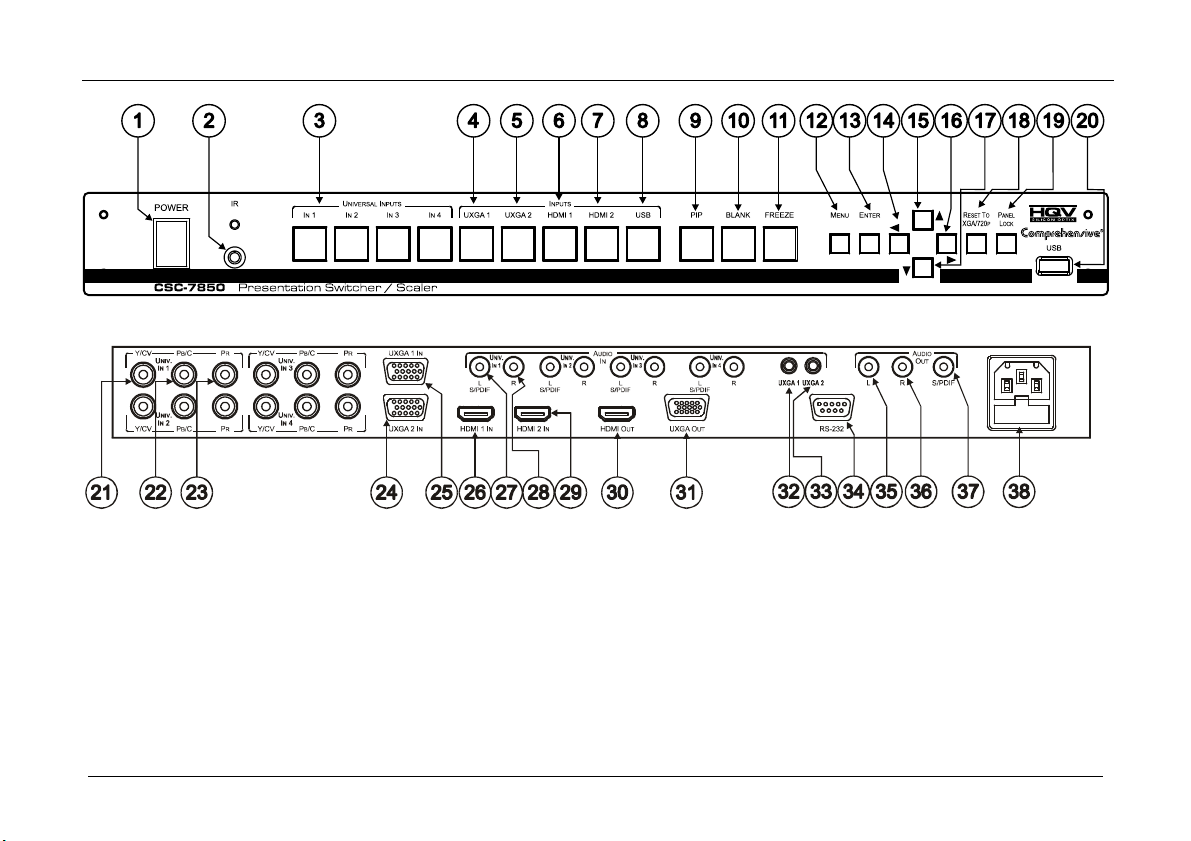
Figure 1, and Table 1 define the front panel of the CSC-7850; Figure 2 and
Table 2 define the rear panel.
1 HDMI provides the quality and functionality of a digital interface while also supporting uncompressed video formats in a
simple, cost-effective manner
4
Page 8
Your Presentation Switcher / Scaler
Figure 1: CSC-7850 Presentation Switcher / Scaler Front Panel
Figure 2: CSC-7850 Presentation Switcher / Scaler Rear Panel
5
Page 9
Your Presentation Switcher / Scaler
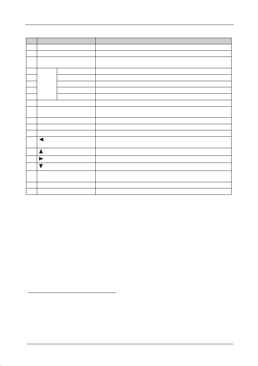
Table 1: Front Panel Presentation Switcher / Scaler Features
# Feature Function
1 POWER Switch Illuminated switch for turning the machine ON or OFF
2 IR Receiver / LED Red when the unit accepts IR remote commands
3 UNIVERSAL INPUT Selector
Buttons
4 UXGA 1 Press to select the UXGA1 source 1
5 UXGA 2 Press to select the UXGA1 source 2
6 HDMI 1 Press to select the HDMI source 1
7 HDMI 2 Press to select the HDMI source 2
8
9 PIP Button Toggles the picture-in-picture function (see section 7.2)
10 BLANK Button Press to toggle between a blank screen (blue or black screen)4 and the
11 FREEZE Button Press to freeze/unfreeze the output video image4
12 MENU Button Displays the OSD menu screen (toggle)
13 ENTER Button Moves to the next level in the OSD screen, or accepts a new parameter
14
15
16
17
18 RESET TO XGA/720p Button Press and hold for a few seconds to reset to the default output
19 PANEL LOCK Button Press to lock/unlock the front panel to prevent unintentional operation
20 USB Connector Connect to a USB drive to read JPEG files6
2
Buttons
USB Press to select the USB3 source
INPUT Selector
Button
Button
Button
Button
Press to select the composite video / s-Video / component video
1
(from 1 to 4)
source
display
Decreases the range by one step in the OSD screen or moves to the
previous level in the OSD screen
Moves up one step (in the same level) in the OSD screen
Increases the range by one step in the OSD screen
Moves down one step (in the same level) in the OSD screen
resolution (XGA/720p @60Hz)5
1 And the appropriate audio source
2 When selected, button illuminates. See section 7.1 for details of how to program the INPUT SELECTOR buttons
3 JPEG files in EXIF format on a USB memory stick
4 Can be programmed to mute the audio signal at the same time (see Table 15)
5 Press and hold for about 2 seconds to reset to XGA; or press and hold for about 5 seconds to reset to 720p
6 Files must be in EXIF format
6
Page 10
Your Presentation Switcher / Scaler
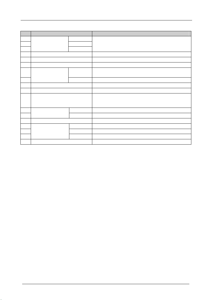
Table 2: Rear Panel Presentation Switcher / Scaler Features
# Feature Function
21 Y/CV
UNIV. IN RCA
Connectors
22 PB/C
(from 1 to 4)
23
24 UXGA 2 IN HD15 Connector Connects to the UXGA (analog interface) graphics source 2
25 UXGA 1 IN HD15 Connector Connects to the UXGA (analog interface) graphics source 1
26 HDMI 1 IN Connector Connect to the HDMI 1 source
27 L, S/PDIF Connect to the left unbalanced stereo analog audio source;
AUDIO IN UNIV. IN
RCA Connectors
(from 1 to 4)
28
29 HDMI 2 IN Connector Connect to the HDMI 2 source
30 HDMI OUT Connector Connect to the HDMI acceptor
31 UXGA OUT HD15 Connector Connects to the video acceptor that displays the scaled output
32 UXGA 1 Connects to the unbalanced stereo analog audio source 1
AUDIO IN 3.5 Mini
Jack
33
34 RS-232 9-pin D-sub Connector Connects to PC or Serial Controller
35 L Connect to the left unbalanced stereo analog audio acceptor
AUDIO OUT RCA
Connectors
36 R Connect to the right unbalanced stereo analog audio acceptor
37
38 Power Connector with Fuse AC connector enabling power supply to the unit
PR
R Connect to the right unbalanced stereo analog audio source
UXGA 2 Connects to the unbalanced stereo analog audio source 2
S/PDIF Connect to a digital audio acceptor
Connect to the video acceptor which can be either composite
video (Y/CV), s-Video (Y/CV, PB/C ) or component video (Y/CV,
PB/C, PR)
Alternatively, connect to a digital audio source
In the default HDTV mode, the signal goes out via 3 PINS: PIN
1 is Pr, PIN 2 is Y, PIN 3 Pb
7
Page 11
Installing in a Rack
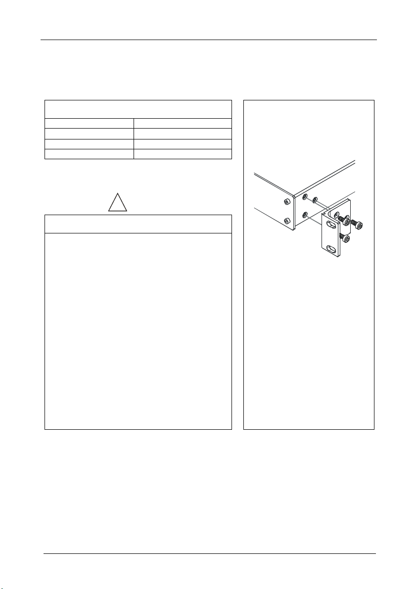
5 Installing in a Rack
This section describes what to do before installing in a rack and how to rack
mount.
Before Installing in a Rack
Before installing in a rack, be sure that the environment is
within the recommended range:
Operating temperature range +5º to +45º C (41º to 113º F)
Operating humidity range 10 to 90% RHL, non-condensing
Storage temperature range -20º to +70º C (-4º to 158º F)
Storage humidity range 5 to 95% RHL, non-condensing
To rack-mount a machine:
1. Attach both ear brackets to the
How to Rack Mount
machine. To do so, remove the
screws from each side of the
machine (3 on each side), and
replace those screws through the
ear brackets.
When installing on a 19" rack, avoid hazards by taking
CAUTION!!
care that:
1. It is located within the recommended environmental
conditions, as the operating ambient temperature of a
closed or multi unit rack assembly may exceed the
room ambient temperature.
2. Once rack mounted, enough air will still flow around
the machine.
3. The machine is placed straight in the correct
horizontal position.
4. You do not overload the circuit(s). When connecting
the machine to the supply circuit, overloading the
circuits might have a detrimental effect on overcurrent
protection and supply wiring. Refer to the appropriate
nameplate ratings for information. For example, for
fuse replacement, see the value printed on the
product label.
5. The machine is earthed (grounded) in a reliable way
and is connected only to an electricity socket with
grounding. Pay particular attention to situations where
electricity is supplied indirectly (when the power cord
is not plugged directly into the socket in the wall), for
example, when using an extension cable or a power
strip, and that you use only the power cord that is
supplied with the machine.
2. Place the ears of the machine
against the rack rails, and insert the
proper screws (not provided)
through each of the four holes in the
rack ears.
Note that:
In some models, the front panel
may feature built-in rack ears
Detachable rack ears can be
removed for desktop use
Always mount the machine in the
rack before you attach any cables
or connect the machine to the
power
8
Page 12

Connecting your Presentation Switcher / Scaler
6 Connecting your Presentation Switcher / Scaler
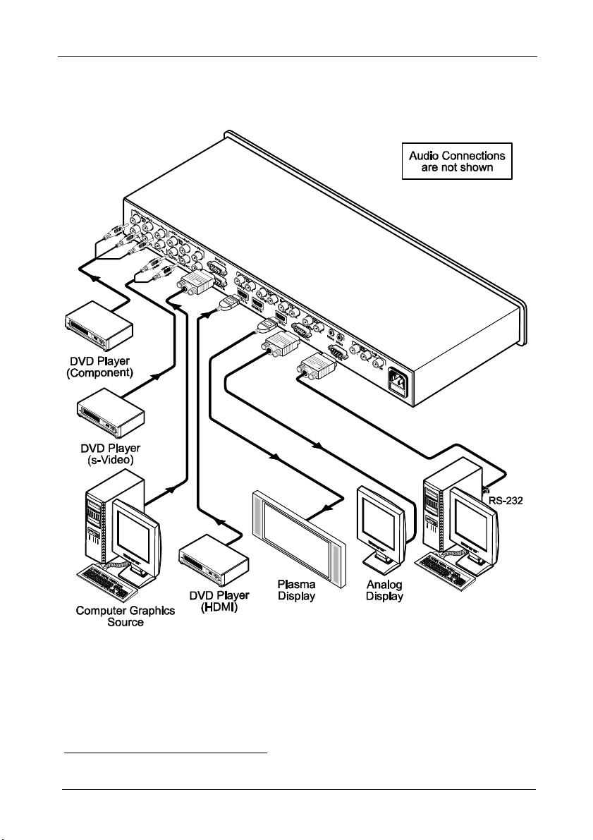
To connect1 the CSC-7850 as illustrated in the example in Figure 3, do the
following2:
1. Connect the following video sources3:
A component video4 source (for example, a DVD player) to the UNIV.
IN 1 RCA connectors, Y/CV, PB/C and PR
An s-Video source (for example, a DVD player) to the UNIV. IN 4 RCA
connectors, Y/CV and PB/C
A computer graphics source to the UXGA 1 IN 15-pin HD computer
graphics video connector
An HDMI source (for example, a DVD player) to the HDMI 1 IN
connector
A graphics data source (for example, JPEG files from a PC or a USB
flash drive) to the USB connector on the front panel of the machine (not
illustrated in Figure 3)
2. Connect the unbalanced stereo or digital audio sources5 (not illustrated in
Figure 3):
The audio of the component video source 1 to the AUDIO UNIV IN 1
S/PDIF RCA connector
The audio of the s-Video source 4 to the AUDIO UNIV IN 4 L and R
RCA connector
The audio of computer graphics source to the AUDIO UXGA 1 3.5mm
mini jack
3. Connect the video outputs:
The HDMI OUT connector to an HDMI acceptor (for example, a plasma
display)
The UXGA OUT 15-pin HD computer graphics video connector6 to a
video acceptor (for example, an analog display)
4. Connect the AUDIO OUT L and R unbalanced stereo audio output and/or
the S/PDIF digital audio output to audio acceptors, for example, speakers
(not illustrated in Figure 3).
1 Although this example shows only several inputs that are connected, you can connect all the inputs simultaneously
2 Switch OFF the power on each device before connecting it to your CSC-7850. After connecting your CSC-7850, switch on
its power and then switch on the power on each device
3 You do not have to connect all the inputs
4 Sometimes called YUV, or Y, B-Y, R-Y, or Y, Pb, Pr
5 As required. Not all devices need to be connected
6 In the HDTV mode, the signal goes out via three PINS: PIN 1 is Red or Pr, PIN 2 is Green or Y, PIN 3 is Blue or Pb
9
Page 13
Connecting your Presentation Switcher / Scaler
5. Connect the power cord1 (the power connector is not illustrated in
Figure 3).
6. If required, connect A PC via RS-232, see section 6.1
Figure 3: Connecting the CSC-7850 Rear Panel
1 We recommend that you use only the power cord that is supplied with this machine
10
Page 14
Connecting your Presentation Switcher / Scaler
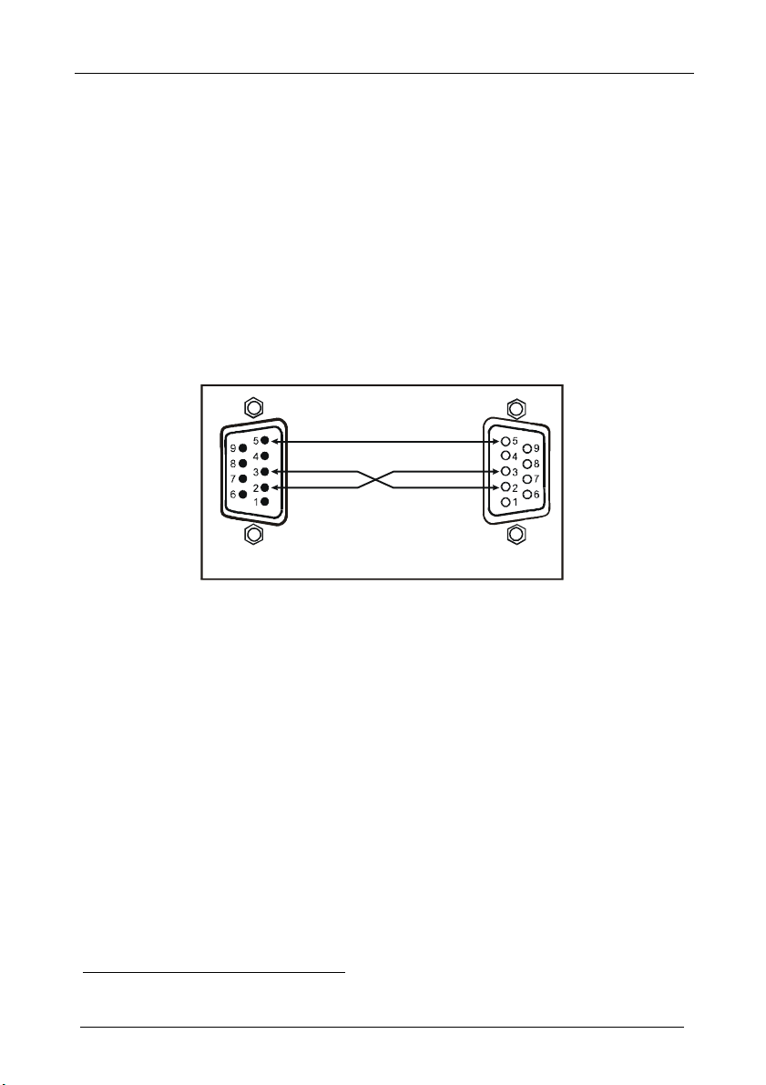
9-pin D-sub
9-pin D-sub
PIN 5 Connected to PIN 5 (Ground)
6.1 Connecting a PC
You can connect a PC (or other controller) to the CSC-7850 via the RS-232
port for remote control, and for upgrading the firmware.
To connect a PC to a CSC-7850 unit, using the Null-modem adapter provided
with the machine (recommended):
Connect the RS-232 9-pin D-sub rear panel port on the CSC-7850 unit to the
Null-modem adapter and connect the Null-modem adapter with a 9-wire flat
cable to the RS-232 9-pin D-sub port on your PC
To connect a PC to a CSC-7850 unit, without using a Null-modem adapter:
Connect the RS-232 9-pin D-sub port on your PC to the RS-232 9-pin D-sub
rear panel port on the CSC-7850 unit, forming a cross-connection1, as Figure 4
illustrates
PIN 3 Connected to PIN 2
PIN 2 Connected to PIN 3
(From PC)
If a shielded cable is used, connect the shield to PIN 5
Figure 4: Connecting the PC
1 Also known as a Null-modem connection
(To Presentation
Switcher/Scaler)
11
Page 15

Presentation Switcher / Scaler Buttons
7 Presentation Switcher / Scaler Buttons
The CSC-7850 includes the following front panel buttons:
Nine INPUT selector buttons, see section 7.1
A PIP button, see section 7.2
BLANK and FREEZE buttons
Six OSD buttons
A RESET TO XGA/720p button
A PANEL LOCK button, see section 7.3
7.1 Switching an Input
Each INPUT SELECTOR button can be used to select the source.
You can switch seamlessly1 between each input that is connected to a source,
by pressing the appropriate INPUT SELECTOR button.
7.2 The PIP Button Feature
The Picture-in-Picture inserter (PIP) uses image insertion technology to
present video and graphic sources simultaneously2. You can display:
An inserted video source3 PIP over a graphic source4 display
An inserted graphic source4 PIP over a video source3 display
Three types of PIP insertions are available:
Picture-in-Picture – the PIP image appears over the background image
Picture + Picture – both the video source and the graphic source are placed side
by side and have the same height (the PIP image is stretched lengthwise)
Split – both the video source and the graphic source are placed side by side (the
PIP image appears smaller than the defined size and the source size is reduced)
1 FTB™ switching for glitchless transitions between inputs
2 Since the HDMI signal is HDCP protected, an HDMI signal cannot appear on a display that is not HDCP compliant
3 That is, composite video, s-Video or component video
4 That is, HDMI, USB or VGA
12
Page 16

Presentation Switcher / Scaler Buttons
7.2.1 Activating the PIP Feature
You can activate the PIP by:
Pressing the PIP button
Pressing the PIP key on the infrared remote control transmitter (see
section 7.4, Figure 7)
Switching on the PIP functionality via the OSD Menu (see Figure 12 and
Table 8)
7.2.2 Selecting the PIP Source
To use the PIP feature, set the PIP source via the OSD menu (see Figure 12 and
Table 8) by using the OSD front-panel buttons or the remote-transmitter keys.
To set the PIP source via the OSD menu, do the following:
1. Press the MENU button to enter the OSD menu.
2. Press the button to move to the PIP icon.
3. Scroll down to select Source and press ENTER.
4. Use the or buttons to select the PIP Source from the drop-down list
box, and press ENTER (see Table 3).
5. To exit the OSD menu, press the MENU button.
Figure 5: PIP Source Over Background
7.2.3 Quick Selection of the PIP Source
For quick selection of the PIP source, press and hold the PIP front panel button
while pressing the input button of the required PIP source. For example, to select
UXGA 2 as the graphic PIP source over a video background, press the PIP front
panel button while pressing the UXGA 2 front panel button.
When attempting to select a PIP source of the same category as the background
source (for example, video on video, which is not compliant to Table 3),
a message is prompted: “unavailable operation”
13
Page 17

Presentation Switcher / Scaler Buttons
To replace a PIP in the same category (for example, changing the PIP source
from UXGA 1 to HDMI 2), press the required PIP Source on the remote control
transmitter and the PIP display will change accordingly.
You can swap the PIP source category with the main source category via the:
Remote control keys, by selecting a new main source and then a new PIP source
OSD menu, by selecting a new Input source through the Input menu and a new
PIP source through the PIP menu
When selecting one PIP source, the Presentation Switcher / Scaler automatically
recognizes and displays the selected graphic PIP source on all the video displays1
and the selected video source on all the graphic1 displays, compliant to Table 3.
Table 3: PIP Source Appearance Availability
The selected PIP
source:
Appears on:
Does not appear on:
7.2.4 Toggling between the PIP and the Screen Source (Swap)
Composite video or s-Video UXGA, HDMI, component video or USB
UXGA, HDMI, component video or USB Composite video or s-Video
Composite video or s-Video UXGA, HDMI, component video or USB
To toggle back and forth between the PIP source and the main display, as
Figure 6 illustrates, press the Swap key on the infra-red remote control
transmitter (see Figure 7).
Figure 6: OSD SWAP Status
1 Even if the input signal is not connected. In this case the PIP appears over a blank screen
14
Page 18

Presentation Switcher / Scaler Buttons
7.3 Locking and Unlocking the Front Panel
To prevent changing the settings accidentally or tampering with the unit via
the front panel buttons, lock your CSC-7850. Unlocking releases the
protection mechanism. When the front panel is locked, control is still
available via RS-232 port.
To lock the CSC-7850:
Press the PANEL LOCK button on the front panel.
The front panel is locked and the PANEL LOCK button is illuminated. Pressing
a button will have no effect
To unlock the CSC-7850:
Press the illuminated PANEL LOCK button on the front panel
The front panel unlocks and the PANEL LOCK button is no longer
illuminated
For a description of the Save Lock and Input Lock OSD functions, see Table
15.
7.4 The Infrared Remote Control Transmitter
You can control the CSC-7850 remotely, from the infrared remote control
transmitter, which:
Is a hand held instrument with a convenient keypad that receives its power from
2 AAA size 1.5V DC batteries
Has a range of up to 15 meters
Delivers instantaneous results
15
Page 19

Presentation Switcher / Scaler Buttons
Figure 7 and Table 4 define the infrared Remote Control Transmitter:
Table 4: Infrared Remote Control Transmitter Functions
key Function
Freeze Pauses the output video1
Blank Toggles between a blank screen (blue or black
POWER Cycles power
Main Source 9 separate keys for selecting each of the
Reset Press and hold to reset to the default resolution2
Info Shows the Info OSD menu
Capture Capture an image to place as a logo or
MENU Shows the main OSD Menu
Navigation arrows Allows maneuvering within an OSD screen (left,
Auto Image Assesses the image and improves the quality
Save Saves a profile
Recall Recalls a profile
Picture Shows the Picture OSD menu
PIP source 9 separate keys for selecting each of the
Mute Mutes the audio signal
Swap Toggles between the PIP content and the parent
PIP Selects the picture-in-picture function and
screen) and the display
following sources: Input 1, Input 2, Input 3, Input
4, VGA 1, VGA2, HDMI 1, HDMI 2 and USB
background (see Table 15)
right, up and down, as well as the ENTER arrow
at the center)
accordingly, by automatically adjusting the
phase, frequency and position
following PIP sources: Input 1, Input 2, Input 3,
Input 4, VGA 1, VGA2, HDMI 1, HDMI 2 and
USB (note, the “USB” key may be excluded on
some remote control transmitters)
screen content
illuminates the PIP button3
Figure 7: Infrared Remote
Control Transmitter
1 Can be programmed to mute the audio signal at the same time (see Table 15)
2 Press and hold for about 2 seconds to reset to XGA; or press and hold for about 5 seconds to reset to 720p
3 See section 7.2
16
Page 20

Configuring the CSC-7850 via the OSD MENU Screens
8 Configuring the CSC-7850 via the OSD MENU Screens
The OSD superimposes a menu on the screen from which you can configure
and control each input signal on your CSC-7850, using the MENU, ENTER,
, , and OSD buttons on the front panel and the remote transmitter.
To use the OSD menus:
1. Select the desired input signal.
2. Use the menu buttons as follows:
Press the MENU front panel OSD button or the MENU key on the
infra-red remote control transmitter (see Figure 7) to display the main
MENU screen1, which displays eight interactive icons (see Figure 8)
Press the MENU front panel OSD button or the MENU key on the
infra-red remote control transmitter to move to the previous level in the
OSD screen (Esc)
Press the UP or DOWN buttons to select menu icons and then press
ENTER
Use + and – buttons to increase and decrease the (numerical) rate
respectively
Figure 8: MENU Items
1 Each icon represents a Level 1 function. In addition to Level 1, the OSD structure includes Level 2 (a subset of level 1),
Level 3 (a subset of level 2), Level 4 (a subset of level 3) and a numerical range
17
Page 21

Configuring the CSC-7850 via the OSD MENU Screens
8.1 The Input Screen
Figure 9 and Table 5 define the Input screen.
Figure 9: Input Screen
Table 5: Input Screen Functions
Setting Function Selection/Range Default
Source1 Select the source2 Input 1, Input 2, Input 3, Input 4, VGA 1, VGA 2,
Input (1 to 4)
Source Type
Image Name Shows the file name3 that is
Color Format Select the color format Auto, RGB or YUV Auto
Video Standard Select the video standard Auto, NTSC, PAL, PAL-M, PAL-N, NTSC 4.43,
H-Position Set the horizontal position4 The range changes according to the input mode
V-Position Set the vertical position The range changes according to the input mode
Frequency Adjust the frequency5 0 to 26 0
Phase Adjust the phase 0 to 31 0
Auto image Assesses the image and improves the quality accordingly, by automatically
Select the source type Component, YC or video (CV) Video
displayed when the USB port
is connected
adjusting the phase, frequency and position
HDMI 1, HDMI 2 or USB
SECAM or PAL-60
Auto
1 When switching sources, the image fades through black
2 Automatically updated when pressing an input front panel button on the machine
3 Supports JPEG format only, including EXIF data (Exchangeable Image File Format). The JPEG file should not exceed a
resolution of 1920x1200. If the image file is not within the definition, the machine displays the message: “Non EXIF File” or
“Size Too Big”
4 For UXGA and component video inputs
5 For UXGA inputs
18
Page 22

Configuring the CSC-7850 via the OSD MENU Screens
8.2 The Picture Screen
Figure 10 and Table 6 define the Picture screen.
Figure 10: Picture Screen
Table 6: Picture Screen Functions
Brightness Adjust the brightness 0 to 100 50
Contrast Adjust the contrast 0 to 100 50
Color Adjust the color 0 to 100 55
Hue Adjust the hue 0 to 360 180
Sharpness Adjust the sharpness 0 to 100 50
Output Gamma Adjust the gamma Gamma 1 to Gamma 5 Gamma 1
Film Mode Set the film mode Auto, Video, Film Auto
Temporal NR Set the temporal noise
Mosquito NR Set the Mosquito noise
Block NR Set the block noise
Detail Enhancement Set the detail
Luma Transition Enhance Set the luminance
Chroma Transition Enhance Set the chrominance
Setting Function Selection/Range Default
Off, Low, Medium, High High
reduction level
Off, Low, Medium, High Low
reduction level
Off, On Off
reduction level
Off, Low, Medium, High Medium
enhancement
Off, Low, High Low
transition enhance level
Off, Low, High Low
transition enhance level
19
Page 23

Configuring the CSC-7850 via the OSD MENU Screens
8.3 The Output Screen
Figure 11 and Table 7 define the Output screen.
Figure 11: Output Screen
Table 7: Output Screen Functions
Setting Function Selection/Range Default
Resolution Set the resolution1 Native HDMI, 640x480x60Hz,
640x480x75Hz, 800x600x60Hz,
800x600x60Hz, 800x600x75Hz,
1024x768x50Hz, 1024x768x60Hz,
1024x768x75Hz, 1280x768x50Hz,
1280x768x60Hz, 1280x1024x50Hz,
1280x1024x60Hz, 1280x1024x50Hz,
1366x768x50Hz, 1366x768x60Hz,
1400x1050x50Hz, 1400x1050x50Hz,
1600x1200x50Hz, 1600x1200x60Hz,
1680x1050x60Hz, 480p, 576p, 720p 50Hz,
720p 60Hz, 1080i 50Hz, 1080i 60Hz, 1080p
50Hz, 1080p 60Hz or Custom
HDMI Type2 Set the HDMI type Auto, HDMI, DVI auto
Aspect Ratio Set the aspect ratio Standard, Letterbox, Anamorphic, Virtual
Wide, Native, Custom
H-Pan2
V-Pan2
H-Zoom 2
V-Zoom2
Zoom Set the Zoom 100%, 150%, 200%, 225%, 250%, 275%,
300%, 325%, 350%, 375%, 400%, Custom2
Custom Zoom2 Set the Zoom From 100% to 400%
Zoom H-Pan2 0 to 31 16
Zoom V-Pan2 0 to 31 16
1024x768@60Hz
Standard
100%
1 Any change in the resolution must be confirmed via the count-down message that appears on the screen
2 Available for versions VTB 1.01 and higher
20
Page 24

Configuring the CSC-7850 via the OSD MENU Screens
8.4 The PIP Screen
Figure 12 and Table 8 define the PIP screen.
Figure 12: PIP Screen
Table 8: PIP Screen Functions
Setting Function Selection/Range Default
On/Off Activate/deactivate the PIP
feature
Type Select the PIP type Picture-In-Picture,
Source Select the PIP source1 Input 1, Input 2, Input 3, Input 4 or USB
UXGA 1, UXGA 2, HDMI 1 or HDMI 2
PIP Size Select the PIP size 1/25, 1/16, 1/9, 1/4, or Custom2 1/4
H-Position Set the horizontal position of the
PIP on the display
V-Position Set the vertical position of the PIP
on the display
H-Size2 Set custom size
V-Size2 Set custom size
Frame Turn the PIP frame on or off On/Off On
Frame Color Select the color of the PIP frame Red, Green or Blue Blue
On/Off Off
Picture + Picture or Split
(for a video PIP source)
0 – 128 3
0 – 128 0
Picture-InPicture
1 When changing the PIP source, the display fades through black
2 Available for versions VTB 1.01 and higher
21
Page 25

Configuring the CSC-7850 via the OSD MENU Screens
8.5 The Audio Screen
Figure 13 and Table 9 define the Audio screen.
Figure 13: Audio Screen
Table 9: Audio Screen Functions
Setting Function Selection/Range Default
Type Select the audio input type1 Analog or S/PDIF Analog
Input Volume Adjust the input volume -22 to 22 0
Output Volume Adjust the output volume -100 to 24 0
Bass Adjust the bass -36 to 36 0
Treble Adjust the treble -36 to 36 0
Balance Adjust the balance -10 to 10 0
Loudness Set the loudness On/Off Off
Delay Define the delay type Dynamic or User Define Dynamic2
User Delay Available when selecting the User
Defined delay
USB Select the audio signal to follow the
USB signal
0 to 3403 (msec) 0
No Audio, Input 1, Input
2, Input 3, Input 4, VGA
1, HDMI 1 or HDMI 2
No Audio
1 Available for IN 1 to IN 4
2 Dynamic means that the audio delay is equal to the pipeline video delay
3 In steps of 2msec
22
Page 26

Configuring the CSC-7850 via the OSD MENU Screens
8.6 The Geometry Screen
Figure 14 and Table 10 define the Geometry screen, allowing the user
flexibility in positioning his projector relative to the screening surface.
Figure 14: Geometry Screen
Table 10: Geometry Screen Functions
Setting Function Selection/Range Default
Application Select the output application Keystone, Anyplace or Rotation Keystone
Location Select the location of the
display
Horizontal Keystone Adjust the horizontal keystone
Front, Rear, Ceiling or Rear ceiling Front
1
-40 to 40 0
Vertical Keystone Adjust the vertical keystone2 -30 to 30 0
Diagonal Projection move the location of each
corner of the display
separately
Pincushion/Barrel Adjust the pincushion or barrel
appearance of the screen
Rotation Rotate the display by 180
degrees clockwise or
counterclockwise
Reset all Resets the geometry values to their default value
Top Left, Top Right, Bottom Left,
Bottom Right or Reset (to reset
diagonal projections settings)
-20 to 20 0
-180 to 180 0
Top Left
Table 11 defines the settings available for each application:
Table 11: Available Settings for Each Application
Application
Keystone Location, horizontal keystone, vertical keystone, pincushion/barrel and Reset all
Anyplace Location, Diagonal Projection and Reset all
Rotation Location, pincushion/barrel, Rotation and Reset all
1 If the projector is located at an angle to the left or right of the screen
2 If the projector is located at an angle above or below the screen
Available Settings
23
Page 27

Configuring the CSC-7850 via the OSD MENU Screens
8.7 The Setup Screen
Figure 15 and Table 10 define the Setup screen.
Figure 15: Setup Screen
Table 12: Setup Screen Functions
Setting Function Selection/Range Default
Save1 Save a profile From Profile 1 to Profile 8
Recall1 Recall a profile From Profile 1 to Profile 8
Frame Lock Locks the vertical refresh rate of the
Factory Reset
Advanced Setup: Open the advanced setups (see
output to that of the input2
Reset your CSC-7850 to its preset
default settings
Figure 16)
On/Off Off
Yes/No
Mode Set (see Table 13)
OSD (see Table 14)
Misc (see Table 15)
Input (see Table 16)
Output (see Table 17)
1 Available for versions VTB 1.01 and higher
2 Note that seamless switching is not possible when working in the Frame Lock mode unless all sources are frame
synchronized
24
Page 28

Configuring the CSC-7850 via the OSD MENU Screens
8.7.1 The Advanced Setup Screen
Figure 16 and Table 14 to Table 17 (inclusive) define the Advanced Setup
screen.
Figure 16: Advanced Setup Screen
The Mode Set functions define the desired working resolution and refresh rate
when the system cannot distinguish between similar resolutions and refresh
rate values (see Table 13).
Table 13: Mode Set Functions
Setting Function Selection/Range Default
Mode 11 Set mode 1 1400x1050x60Hz
1680x1050@60Hz
Mode 21 Set mode 2 1280x1024x75Hz
1280x1024x76Hz
1400x1050x60Hz
1280x1024x75Hz
Table 14: OSD Functions
Setting Function Selection/Range Default
Menu Position Set the location of the OSD menu Center, Top Left, Bottom
Left, Bottom right
Time Out (sec) Set the OSD menu timeout 5, 10, 20, 30, 60, 90 or Off 30
Top Right
1 Available for versions VTB 1.01 and higher
25
Page 29

Configuring the CSC-7850 via the OSD MENU Screens
Table 15: Misc Functions
Setting Function Selection/Range Default
Logo Choose ON for the start up logo to
Blank Color Set the blank color (the color that
Capture Press to capture the desired
Background Set the background screen color Blue, Black, Custom3 Default
Save Lock Set the Save Lock option to ON to
Input Lock Set the Input Lock to OFF so you
Firmware Download Download the firmware via the
Logo Download Download a new logo via the USB
Blank Define the function of the BLANK
Freeze Define the function of the
appear on the screen
OFF for it not to appear
Set to Custom to download a
custom Logo
appears on the screen when the
blank button is pressed)
image input2 to Flash ROM for
using as a logo or as the
background
save the lock status when the
machine is powered down
can still use the SOURCE buttons
on the front panel even when the
lock button is on
USB connection (see Figure 17)
connection
front panel button
FREEZE front panel button
1
(Flash ROM)
On, Off or Custom Logo
Black or Blue Blue
Prompts “Capture”
If the image size is not within
the definition, prompts “Size
Too Big”
On/Off Off
On/Off Off
Confirmation
Blank & Mute, Blank, Mute Blank & Mute
Freeze & Mute, Freeze, Mute Freeze &
Mute
Figure 17: Firmware Download Screen
1 Obtained via the Capture function or downloaded via USB
2 The capture image size should not exceed 1280x1024
3 Obtained via the Capture function or downloaded via USB. Available for versions VTB 1.01 and higher
26
Page 30

Configuring the CSC-7850 via the OSD MENU Screens
1
Table 16: Input Functions
Setting Function
H Total Horizontal Total
H Start Horizontal active start point
H Active Horizontal active region
V Total Vertical Total
V Start Vertical active start point
V Active Vertical active region
Ch, Pump Charge pump current
H Freq Horizontal Frequency
V Freq Vertical Frequency
Color Color format
Save Save settings
Erase Erase settings
Measure Select between Default and User Define
Table 17: Output Functions1
Setting Function
HT Horizontal total
HW Horizontal sync pulse width
HS Horizontal active start point
HA Horizontal active region
HP Horizontal polarity
VT Vertical total
VW Vertical sync pulse width
VS Vertical active start point
VA Vertical active region
VP Vertical polarity
OCLK Output clock
Confirm Confirm the action
Discard Cancel the action
Set Current Import the values of the currently selected output resolution into the User
Mode Setting
1 Available for versions VTB 1.01 and higher
27
Page 31

Configuring the CSC-7850 via the OSD MENU Screens
8.8 Verifying Configuration Details via the Info Screen
From the Information screen (see Figure 18), you can verify the main source,
PIP source, the output resolution, the SYNC mode, as well as the firmware
version number:
Figure 18: Information Screen
28
Page 32

Technical Specifications
9 Technical Specifications
Table 18 includes the technical specifications:
Table 18: Technical Specifications1 of the CSC-7850 Presentation Switchers / Scaler
INPUTS:
OUTPUTS: 1 HDMI connector
COMPLIANCE WITH
HDMI STANDARD:
OUTPUT
RESOLUTIONS:
CONTROL: Front panel buttons / OSD, IR remote control, RS-232 on a 9-pin D-sub connector,
ADDITIONAL
CONTROLS:
POWER SOURCE: 100-240 VAC, 50/60 Hz, 30VA automatic power supply
DIMENSIONS: 19" (W), 9.3" (D) 1U (H) rack mountable
WEIGHT: 3kg (6.6lbs.) approx.
ACCESSORIES: Null modem adapter, IR remote control, power cord
4 x universal Y/CV, Pb/C, Pr (composite, s-Video and component) 1 Vpp/75 on RCA
connectors;
2 x UXGA on an HD15F connector (VGA through UXGA)
2 x HDMI connectors
1 x USB connector
For each universal input there is a corresponding (unbalanced) audio stereo input and
digital S/PDIF input on RCA connectors
For each UXGA input there is a corresponding (unbalanced) audio stereo input on a
3.5mm mini jack connector
1 UXGA format on an HD15 connector
1 unbalanced audio stereo output on RCA connectors
1 digital S/PDIF output on an RCA connector
Supports HDMI 1.3 and HDCP
Native HDMI, 640x480x60Hz, 640x480x75Hz, 800x600x60Hz, 800x600x60Hz,
800x600x75Hz, 1024x768x50Hz, 1024x768x60Hz, 1024x768x75Hz, 1280x768x50Hz,
1280x768x60Hz, 1280x1024x50Hz, 1280x1024x60Hz, 1280x1024x50Hz,
1366x768x50Hz, 1366x768x60Hz, 1400x1050x50Hz, 1400x1050x50Hz,
1600x1200x50Hz, 1600x1200x60Hz, 1680x1050x60Hz, 480p, 576p, 720p 50Hz, 720p
60Hz, 1080i 50Hz, 1080i 60Hz, 1080p 50Hz, 1080p 60Hz or Custom
Picture-In-Picture: Video in Graphics (or vice versa) in any size and at any location, or
Split Screen (2 images side-by-side)
Freeze, zoom, different selectable vertical refresh rates, Video and Audio ProcAmp
control, output image scaling and aspect ratio change
1 Specifications are subject to change without notice
29
Page 33

Technical Specifications
Table 19: Technical Specifications of the RGBHV / RGBS (PC) / RGsB (PC) Signal
Resolution Vertical
Frequency (Hz)
640x480 60 1024x768 85
640x480 67 Mac13 1024x800 84 Sun
640x480 72 1152x864 75
640x480 75 1152x870 75 Mac21
640x480 85 1152x900 66 Sun
720x400 70 1152x900 76 Sun
720x400 85 1280x960 60
800x600 56 1280x960 85
800x600 60 1280x768 60
800x600 72 1280x1024 60
800x600 75 1280x1024 75
800x600 85 1280x1024 76 Sun(12/1)
832x624 75 Mac16 1280x1024 85
1024x768 60 1400x1050 60
1024x768 70 1400x1050 75
1024x768 75 1600x1200 60
1024x768 75 Mac19 1680x1050 60 (12/1)
Notes Resolution Vertical
Frequency (Hz)
Notes
Table 20: Technical Specifications of the Y/C, Video Signal
Standard
NTSC, NTSC4.43, PAL, PAL-M, PAL-N, SECAM, PAL-60
Table 21: Technical Specifications of the DVI Signal (for RGB Colorspace)
Resolution Vertical
Frequency (Hz)
640x480 60 1024x768 85
640x480 67 Mac13 1024x800 84 Sun
640x480 72 1152x864 75
640x480 75 1152x870 75 Mac21
640x480 85 1152x900 66 Sun
720x400 70 1152x900 76 Sun
720x400 85 1280x960 60
800x600 56 1280x960 85
800x600 60 1280x768 60
800x600 72 1280x1024 60
800x600 75 1280x1024 75
800x600 85 1280x1024 76 Sun(12/1)
832x624 75 Mac16 1280x1024 85
1024x768 60 1400x1050 60
1024x768 70 1400x1050 75
1024x768 75 1600x1200 60
1024x768 75 Mac19 1680x1050 60 (12/1)
Notes Resolution Vertical
Frequency (Hz)
Notes
30
Page 34

Technical Specifications
Table 22: Technical Specifications of the HDMI Signal (for RGB or YUV Colorspace)
Resolution Vertical Frequency (Hz) Remark
1080i 60 YPbPr
1080i 50 YPbPr
1080p 60 YPbPr
1080p 50 YPbPr
720p 60 YPbPr
720p 50 YPbPr
480i 60 YPbPr
480p 60 YPbPr
576i 50 YPbPr
576p 50 YPbPr
Table 23: Technical Specifications of the Component Input Signal
Resolution Vertical Frequency (Hz) Remark
1080i 60 YPbPr
1080i 50 YPbPr
1080p 60 YPbPr
1080p 50 YPbPr
720p 60 YPbPr
720p 50 YPbPr
480i 60 YPbPr
480p 60 YPbPr
576i 50 YPbPr
576p 50 YPbPr
31
Page 35

Technical Specifications
Table 24: Technical Specifications of the RGBHV/Comp/YPbPr Output Signal
Resolution Vertical Frequency (Hz) Remark
640x480 60
640x480 75
800x600 50
800x600 60
800x600 75
1024x768 50
1024x768 60
1024x768 75
1280x768 50
1280x768 60
1280x1024 50
1280x1024 60
1280x1024 75
1366x768 50
1366x768 60
1400x1050 50
1400x1050 60
1600x1200 50
1600x1200 60
1920x1080 60 RGBHV
1680x1050 60 VESA
1080i 60
1080i 50
720p 60
720p 50
480p 60
576p 50
1080p 50
1080p 60
RGBHV
Comp/YPbPr
32
Page 36

Technical Specifications
Table 25: Technical Specifications of the HDMI/DVI/RGB Output Signal
Resolution Vertical Frequency (Hz) Remark
640x480 60
640x480 75
800x600 50
800x600 60
800x600 75
1024x768 50
1024x768 60
1024x768 75
1280x768 50
1280x768 60
1280x1024 50
1280x1024 60
1280x1024 75
1366x768 50
1366x768 60
1400x1050 50
1400x1050 60
1600x1200 50
1600x1200 60
1920x1080 60
1680x1050 60 VESA
1080i 60
1080i 50
720p 60
720p 50
480p 60
576p 50
1080p 50
1080p 60
DVI/RGB
HDMI
Table 26: Technical Specifications of the 1920x1080 Output Signal
Standard Timing
VESA
(non-CRT)
V Front
porch
+ Bottom
border
2 5 24 1118 POS NEG
1920x1080x60 138.625 48 32 80 2080
V Sync Width
Pixel clock
(MHz)
V Back porch +
Top border
H Front porch
+ Right border
V Total
H Sync
Width
Hsync
polarity
H Back porch +
Left border
Vsync
polarity
H Total
33
Page 37

CSC-7850 Communication Protocol
10 CSC-7850 Communication Protocol
Serial Configuration:
Baud rate: 9600 (Bits per second)
Data bits: 8bits
Parity: None
Stop bits: 1bit
Communication confirmation:
Send: CR
Reply: CR>
Set Command:
Send: YControl_TypeFunctionParamCR
Reply: ZControl_TypeFunctionParamCR>
Get Command:
Send: YControl_TypeFunctionCR
Reply: ZControl_TypeFunctionParamCR>
Example: set Input 1 Source Type to Component
Send: Y000CR
Reply: Z000CR>
Example: get current Input 1 Source Type
Send: Y10CR
Reply: Z100CR >
34
Page 38

CSC-7850 Communication Protocol
Picture Output Gamma
Control Type
Set Get
0 1 0
0 1 1
0 1 2
0 1 3
0 1 4
0 1 5
0 1 6
0 1 7 -50 ~ 50 Input H-Position
0 1 8 -40 ~ 40 Input V-Position
0 1 9 -50 ~ 50 Input Frequency
0 1 10 0 ~ 31 Input Phase
0 - 11 - Input Auto Image
0 1 12 0~100 Picture Brightness
0 1 13 0~100 Picture Contrast
0 1 14 0~100 Picture Color
0 1 15 0~360 Picture Hue
0 1 16 0~100 Picture Sharpness
0 1 17
0 1 18
Function Parameter Description
0: Input 1
1: Input 2
2: Input 3
3: Input 4
4: VGA 1
5: VGA 2
6: HDMI 1
7: HDMI 2
8: USB
0: Component
1: YC
2: Video
0: Component
1: YC
2: Video
0: Component
1: YC
2: Video
0: Component
1: YC
2: Video
0: Auto
1: RGB
2: YUV
0: Auto
1: NTSC
2: PAL
3: PAL-M
4: PAL-N
5: NTSC 4.43
6: SECAM
7: PAL-60
0: Gamma 1
1: Gamma 2
2: Gamma 3
3: Gamma 4
4: Gamma 5
0: Auto
1: Video
2: Film
Input Source
Input 1 Source Type
Input 2 Source Type
Input 3 Source Type
Input 4 Source Type
Input Color Format
Input Video Standard
Picture Film Mode
35
Page 39

CSC-7850 Communication Protocol
Control Type
Set Get
0 1 19
0 1 20
0 1 21
0 1 22
0 1 23
0 1 24
0 1 25
Function Parameter Description
0: Off
1: Low
2: Medium
3: High
0: Off
1: Low
2: Medium
3: High
0: Off
1: On
0: Off
1: Low
2: Medium
3: High
0: Off
1: Low
2: High
0: Off
1: Low
2: High
0 : Native HDMI
1 : 640x480@60Hz
2 : 640x480@75Hz
3 : 800x600@50Hz
4 : 800x600@60Hz
5 : 800x600@75Hz
6 : 1024x768@50Hz
7 : 1024x768@60Hz
8 : 1024x768@75Hz
9 : 1280x768@50Hz
10: 1280x768@60Hz
11: 1280x1024@50Hz
12: 1280x1024@60Hz
13: 1280x1024@75Hz
14: 1366x768@50Hz
15: 1366x768@60Hz
16: 1400x1050@50Hz
17: 1400x1050@60Hz
18: 1600x1200@50Hz
19: 1600x1200@60Hz
20: 1680x1050@60Hz
21: 480p@60Hz
22: 576p@60Hz
23: 720p@50Hz
24: 720p@60Hz
25: 1080i@50Hz
26: 1080i@60Hz
27: 1080p@50Hz
28: 1080p@60Hz
29: Custom
Picture Temporal NR
Picture Mosquito NR
Picture Block NR
Picture Detail
Enhancement
Picture Luma Transition
Enhance
Picture Chroma Transition
Enhance
Output Resolution
36
Page 40

CSC-7850 Communication Protocol
Control Type
Set Get
0 1 26
0 1 27
0 1 28 -64 ~ 64 H-Pan
0 1 29 -64 ~ 64 V-Pan
0 1 30 -32 ~ 32 H-Zoom
0 1 31 -32 ~ 32 V-Zoom
0 1 32
0 1 33 100 ~ 400 Custom Zoom
0 1 34 0 ~ 31 Zoom H-Pan
0 1 35 0 ~ 31 Zoom V-Pan
0 1 36
0 1 37
0 1 38
0 1 39
0 1 40 0 ~ 128 PIP H-Position
0 1 41 0 ~ 128 PIP V-Position
0 1 42 1 ~ 32 PIP H-Size
0 1 43
Function Parameter Description
0: Auto
1: HDMI
2: DVI
0: Standard
1: Letterbox
2: Anamorphic
3: Virtual Wide
4: Native
5: Custom
0: 100%
1: 150%
2: 200%
3: 225%
4: 250%
5: 275%
6: 300%
7: 325%
8: 350%
9: 375%
10: 400%
11: Custom
0: On
1: Off
0: Picture-In-Picture
1: Picture + Picture
2: Split
0: Input 1
1: Input 2
2: Input 3
3: Input 4
4: VGA 1
5: VGA 2
6: HDMI 1
7: HDMI 2
8: USB
0: 1/25
1: 1/16
2: 1/9
3: 1/4
4: Custom
1 ~ 32
Output HDMI Type
Aspect Ratio
Zoom
PIP On/Off
PIP Type
PIP Source
PIP Size
PIP V-Size
37
Page 41

CSC-7850 Communication Protocol
Control Type
Set Get
0 1 44
0 1 45
0 1 46
0 1 47 -22~0~+22 Audio Input Volume
0 1 48 -100~24 Audio Output Volume
0 1 49 -36~0~+36 Audio Bass
0 1 50 -36~0~+36 Audio Treble
0 1 51 -10~10 Audio Balance
0 1 52
0 1 53
1 54 0~340(step 2) User Delay
0 1 55
0 1 56
0 1 57
0 1 58 -40 ~ 40
0 1 59 -30~30
0 1 60
0 1 61 -20 ~ 20
0 1 62 -180 ~ 180 Geometry Rotation
0 - 63 - Geometry Reset all
0 - 64 1 ~ 8 Save Setting
0 - 65 1 ~ 8 Recall Setting
0 1 66
0 - 67 - Factory Reset
Function Parameter Description
0: On
1: Off
0: Red
1: Green
2: Blue
0: Analog
1: S/PDIF
0: Off
1: On
0: Dynamic
1: User Define
0: No audio
1: Input 1
2: Input 2
3: Input 3
4: Input 4
5: VGA1
6: VGA2
7: HDMI1
8: HDMI1
0: Keystone
1: Anyplace
2: Rotation
0: Front
1: Rear
2: Ceiling
3: Rear ceiling
0: Top Left
1: Top Right
2: Bottom Left
3: Bottom Right
4: Reset
0: On
1: Off
PIP Frame
PIP Frame Color
Audio Input Type
Audio Loudness
Audio Delay
Audio Input For USB
Geometry Application
Geometry Location
Geometry Horizontal
Keystone
Geometry Vertical
Keystone
Geometry Diagonal
Projection
Geometry
Pincushion/Barrel
Frame Lock
38
Page 42

CSC-7850 Communication Protocol
Control Type
Set Get
- 1 68 - Firmware Revision
0 1 69
0 1 70
0 1 71
0 1 72
0 1 73
0 1 74
0 - 75 - Capture
0 1 76
0 1 77
0 1 78
0 - 79
0 - 80
0 1 81
0 1 82
0 1 83
0 - 84 - Info
0 - 85 - Menu
0 - 86 - Top
0 - 87 - Down
0 - 88 - Left
0 - 89 - Right
0 - 90 - Enter
0 - 91 - Picture
Function Parameter Description
0: 1400x1050x60
1: 1680x1050x60
0: 1280x1024x75
1: 1280x1024x76
0: Center
1: Top Left
2: Top Right
3: Bottom Left
4: Bottom Right
0: 5 sec
1: 10 sec
2: 20 sec
3: 30 sec
4: 60 sec
5: 90 sec
6: Off
0: On
1: Off
2: Custom
0: Blue
1: Black
0: Blue
1: Black
0: Off
1: On
0: Off
1: On
0: Blank & Mute
1: Blank
2: Mute
0: Freeze & Mute
1: Freeze
2: Mute
0: Off
1: On
0: Off
1: On
0: Off
1: On
Mode Set – Mode 1
Mode Set – Mode 2
OSD Menu Position
OSD Time Out
Logo
Blank Color
Background
Save Lock
Input Lock
Blank key function
Freeze key function
Freeze
Blank
Power
39
Page 43

CSC-7850 Communication Protocol
Control Type
Set Get
0 -- 92 - Swap
0 1 93
0 1 94
- 1 95
Function Parameter Description
0: Off
1: On
0: Off
1: On
0: 640x480 60
1: 640x480 67 Mac13
2: 640x480 72
3: 640x480 75
4: 640x480 85
5: 720x400 70
6: 720x400 85
7: 800x600 56
8: 800x600 60
9: 800x600 72
10: 800x600 75
11: 800x600 85
12: 832x624 75 Mac16
13: 1024x768 60
14: 1024x768 70
15: 1024x768 75
16: 1024x768 75 Mac19
17: 1024x768 85
18: 1024x800 84 Sun
19: 1152x864 75
20: 1152x870 75 Mac21
21: 1152x900 66 Sun
22: 1152x900 76 Sun
23: 1280x960 60
24: 1280x960 85
25: 1280x768 60
26: 1280x1024 60
27: 1280x1024 75
28: 1280x1024 76 Sun
29: 1280x1024 85
30: 1400x1050 60
31: 1400x1050 75
32: 1600x1200 60
33: 1680x1050 60
34: 1080i 60
35: 1080i 50
36: 1080p 60
37: 1080p 50
38: 720p 60
39: 720p 50
40: 480i
41: 480p
42: 576i
43: 576p
98: other
99: No Input detected
101: NTSC
Mute
Lock
Main Input status
40
Page 44

CSC-7850 Communication Protocol
Control Type
Set Get
- 1 96
Function Parameter Description
102: PAL
103: PAL-M
104: PAL-N
105: NTSC 4.43
106: SECAM
107: PAL-60
0: 640x480 60
1: 640x480 67 Mac13
2: 640x480 72
3: 640x480 75
4: 640x480 85
5: 720x400 70
6: 720x400 85
7: 800x600 56
8: 800x600 60
9: 800x600 72
10: 800x600 75
11: 800x600 85
12: 832x624 75 Mac16
13: 1024x768 60
14: 1024x768 70
15: 1024x768 75
16: 1024x768 75 Mac19
17: 1024x768 85
18: 1024x800 84 Sun
19: 1152x864 75
20: 1152x870 75 Mac21
21: 1152x900 66 Sun
22: 1152x900 76 Sun
23: 1280x960 60
24: 1280x960 85
25: 1280x768 60
26: 1280x1024 60
27: 1280x1024 75
28: 1280x1024 76 Sun
29: 1280x1024 85
30: 1400x1050 60
31: 1400x1050 75
32: 1600x1200 60
33: 1680x1050 60
34: 1080i 60
35: 1080i 50
36: 1080p 60
37: 1080p 50
38: 720p 60
39: 720p 50
40: 480i
41: 480p
42: 576i
43: 576p
98: other
99: No Input detected
PIP Input status
41
Page 45

CSC-7850 Communication Protocol
Control Type
Set Get
Function Parameter Description
101: NTSC
102: PAL
103: PAL-M
104: PAL-N
105: NTSC 4.43
106: SECAM
107: PAL-60
42
Page 46

Comprehensive
55 Ruta Court
South Hackensack, NJ 07606
Phone: 800-526-0242
Fax: 201-814-0510
Website: www.comprehensiveinc.com
E-Mail: sales@comprehensiveinc.com
 Loading...