

Page 1
CE-HDBT100
HDMI/IR/RS232 Twisted Pair over Single Cable
Please read this manual car ef ul l y before using this product.
Page 2

HDMI Twisted Pair
SAFETY PRECAUTIONS
Please read all instructions before attempting to unpack, install or operate this equipment
and before connecting the power supply.
Please keep the following in mind as you unpack and install this equipment:
• Always follow basic safety precaution to reduce the risk of fire, electrical shock and injury
to persons.
• To prevent fire or shock hazard, do not expose the unit to rain, moisture or install this
product near water.
• Never spill liquid of any kind on or into this product.
• Never push an object of any ki nd i nt o this product thr ough any opening s or empty slots in
the unit, as you may damage parts inside the unit.
• Do not attach the power supply cabling to building surfaces.
• Use only the supplied power supply unit (PSU). Do not use the PSU if it is damaged.
• Do not allow anything to rest on the power cabling or allow any weight to be placed upon
it or any person walk on it.
• To protect the unit from overheating, do not block any vents or openings in the unit
housing that provide ventilation and allow for suff icient space for air circulate around the
unit.
- 2 -
Page 3
HDMI Twisted Pair
Index:
1. General Instruction .................................................................................................................................. 3
2. Product Picture ......................................................................................................................................... 3
3. Features .................................................................................................................................................... 3
4. Specification ............................................................................................................................................ 4
5. Function Description ............................................................................................................................... 5
6. Installation Introduction ........................................................................................................................... 7
7. Diagram and Connection ......................................................................................................................... 7
8. Twisted Pair Cable Connection ................................................................................................................ 8
9. Panel Drawing
......................................................................................................................................... 8
1. General Instruction:
CE-HDBT100 is an HDMI/IR/RS232 twisted pair including transmitter (CE-HDBT100T) and receiver (CE-HDBT100R).
The CE-HDBT100 uses HDBaseT technology to deliver HDMI signal and control signal (IR & RS232), over a single STP
cable, max transmission distance up to 70 meters with CAT5e/CAT6 cable.
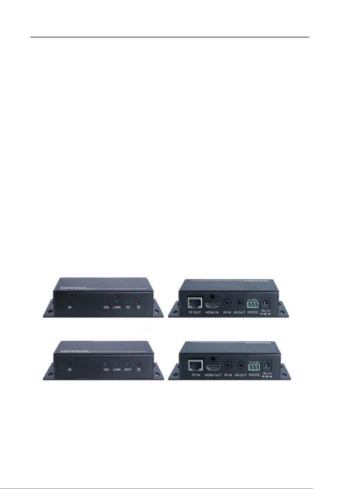
2. Product Picture:
3. Features:
· Support Full HD: Delivers high resolution image (1080p@60Hz@48 b/pixels/3D/4Kx2K).
Max transmission distance is up to 70 meters over single CAT5e/CAT6 cable.
·
TPHD402R Receiver
- 3 -
Page 4

HDMI Twisted Pair
Differential Phasic
· High Bandwidth: 10.2Gps.
· HDTV Compatible. HDMI 1.4 and HDCP compliant.
· Bi-directional RS232 control.
· Bi-directional IR control.
· Use HDBaseT technology.
· LED indicators show work status.
· HDMI cable locking screw nut.
· Wall/table-mountable aluminium enclosure, PT case design.
· External international power supply (100Volt~240Volt AC, 50/60Hz).
4. Specification
Model
Spec
Input
Input Signal 1 HDMI,1 IR & 1 RS232 1 IR, 1 RJ-45 & 1 RS232
Input Connector HDMI female, 3.5mm mini jack 3.5mm mini jack, RJ-45
Video Signal HDMI1.4 HDMI1.4
Audio
Output
Output 1 RJ-45, 1 IR 1 HDMI, 1 IR
Output Connector RJ-45, 3.5mm mini jack HDMI female, 3.5mm mini jack
Video signal HDMI1.4 HDMI1.4
Transmission Mode HD Base T
General
Resolution Range 800x600 ~ 1920x1200
Transmission
Distance
Gain 0dB ~ 10dB@100MHz
Erro
SNR >70dB@ 100MHz-100M
Bandwidth 10.2Gbps
Return Lost <-30dB@5KHz
THD <0.005%@1KHz
HDMI Standard Support HDMI1.4 and HDCP
Min. ~Max. Level <0.3V ~ 1.45Vp-p
Impedance 75Ω
Digital audio, transmit through HDMI
audio
Max distance 70M
±10° @ 135MHz_100M
CE-HDBT100T CE-HDBT100R
Digital audio, transmit through HDMI
audio
- 4 -
Page 5

HDMI Twisted Pair
Temperature -20 ~ +60℃
Humidity 10% ~ 90%
Power Supply 100VAC ~ 240VAC, 50/60Hz
Power
6.5W
Consumption
Case Dimension L134xW77xH30mm L134xW77xH30mm
Net Weight 0.8Kg 0.8Kg
NOTE: All nominal levels are at ±10%.
5. Function Description
5.1 Transmitter Introduction
1) IR: IR receiver.
2) ON/LINK/IN LED Indicators: All are green LED.
ON: Working status indicator of this device. When the device works fine, the LED will keep blinking. And
it will get off when the device stops work.
- 5 -
Page 6

HDMI Twisted Pair
LINK: Twisted Pair Link status indicator. It will keep on when connection is successful.
IN: When connected with devices support HDCP and work normally this LED will keep on. If devices not
support HDCP, the LED will blink.
3) POWER LED: LED indicator of po w er. When connect with power, red LED will keep on.
4) TP OUT: Single TP cable connects to TP IN port in CE-HDBT100R.
5) HDMI IN: Connect to HDMI source.
6) IR IN: Connect with IR receiver, the IR signal received from this port can only send out in CE-HDBT100R.
NOTICE: When there is IR receiver connected to this port, the port (1) will be unavailable.
7) IR OUT: Connect with IR sender, the sending IR signal are received from CE-HDBT100R.
8) RS232: RS232 connector.
9) 5V DC: Connect with power supply.
5.2 Receiver Introduction:
1) IR: IR receiver.
2) ON/LINK/IN LED Indicators: All are green LED.
ON: Working status indicator of this device. When the device works fine, the LED will keep blinking. And
it will get off when the device stops work.
LINK: Twisted Pair Link status indicator. It will keep on when connection is successful.
- 6 -
Page 7

HDMI Twisted Pair
IN: When connected with devices support HDCP and work normally this LED will keep on. If devices not
support HDCP, the LED will blink.
3) POWER LED: LED indicator of po w er. When connect with power, red LED will keep on.
4) TP IN: Single TP cable connects to TP OUT port in CE-HDBT100T.
5) HDMI OUT: Connect to HDMI display, HDMI signal output.
6) IR IN: Connect with IR receiver, the IR signal received from this port can only send out in CE-HDBT100T.
NOTICE: When there is IR receiver connected to this port, the port (1) will be unavailable.
7) IR OUT: Connect with IR sender, the sending IR signal are received from CE-HDBT100R.
8) RS232: RS232 connector.
9) 5V DC: Connect with power supply.
6. Installation Introduction
Step 1: Connect HDMI source (such as Blue-ray DVD) to HDMI IN port of transmitter CE-HDBT100T with HDMI
cable.
Step 2: Connect TP OUT port of TPHD401T and TP IN port of TPHD401R, with single C AT5e/CAT6 cable.
Step 3: Connect HDMI displayer (such as HDTV) to HDMI OUT port of CE-HDBT100R with HDMI cable.
Step 4: Connect DC5V power adaptors to both CE-HDBT100T and CE-HDBT100R.
Step 5: Both CE-HDBT100T and CE-HDBT100R have IR IN and OUT. When one model use for IR signal receiver,
the IR signal must be sent out by the other model.
For example: When “IR IN” of CE-HDBT100T connects with an IR receiver, the IR sender must connect to “IR
OUT” of CE-HDBT100R.
7. Diagram and connection
- 7 -
Page 8

HDMI Twisted Pair
8. Twisted Pair Cable Connection
TIA/EIA T568A TIA/EIA T568B
Pin Cable color Pin Cable color
1 green white 1 orange white
2 green 2 orange
3 orange white 3 green white
4 blue 4 blue
5 blue white 5 blue white
6 orange 6 green
7 brown white 7 brown white
8 brown 8 brown
1st Ground 4--5 1st Ground 4--5
2nd Ground 3--6 2nd Ground 1--2
3rd Group 1--2 3rd Group 3--6
4th Group 7--8 4th Group 7--8
Notice: Cable connectors MUST be metal one, the shielded layer of cable MUST be connected to the
connector’s metal shell, to make a better transmission.
9. Panel Drawing
Unit: mm
- 8 -
Page 9

HDMI Twisted Pair
- 9 -
 Loading...