

Page 1
OOppeerraattiioonn MMaannuuaal
l
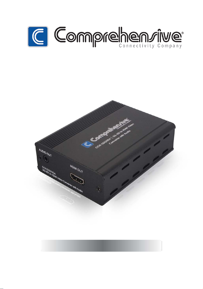
CCN-SDI2HDA
3G SDI to HDMI Converter
Page 2

DISCLAIMERS
The information in this manual has been carefully checked and
is believed to be accurate. Comprehensive assumes no
responsibility for any infringements of patents or other rights of third
parties which may result from its use.
Comprehensive assumes no responsibility for any inaccuracies that
may be contained in this document. Comprehensive also makes
no commitment to update or to keep current the information
contained in this document.
Comprehensive reserves the right to make improvements to this
document and/or product at any time and without notice.
COPYRIGHT NOTICE
No part of this document may be r epr odu c ed, transmitted,
transcribed, stored in a retrieval system, or any of its part translated
into any language or computer file, in any form or by any means—
electronic, mec hanical, magnetic, optical, chemical, manual, or
otherwise—without express written permission and consent from
Comprehensive
© Copyright 2011 by
Rights Reserved.
Version 1.1 August 2011
.
Comprehensive
. All
TRADEMARK ACKNOWLEDGMENTS
All products or service names mentioned in this document may be
trademarks of the companies with which they are associated.
Page 3

SAFETY PRECAUTIONS
Please read all instructions before attempting to unpack, install or
operate this equipment and before connecting the power supply.
Please keep the following in mind as you unpack and install this
equipment:
• Always follow basic safety precautions to reduce the risk of fire,
electrical shock and injury to persons.
• To prevent fire or shock hazard, do not expose the unit to rain,
moisture or install this product near water.
• Never spill liquid of any kind on or into this product.
• Never push an object of any kind into this product through any
openings or empty slots in the unit, as you may damage parts
inside the unit.
• Do not attach the power supply cabling to building surfaces.
• Use only the supplied power supply unit (PSU). Do not use the PSU
if it is damaged.
• Do not allow anything to rest on the power cabling or allow any
weight to be placed upon it or any person walk on it.
• To protect the unit from overheating, do not block any vents or
openings in the unit housing that provide ventilation and allow for
sufficient space for air to circulate around the unit.
REVISION HISTORY
VERSION NO. DATE DD/MM/YY SUMMARY OF CHANGE
VS1 23/02/12
VR2 12/03/12 Add Output Timings
VS3 11/07/12
First release
SDI standards updated
Page 4

CONTENTS
1. Introduction ..................................... 1
2. Applications .................................... 1
3. Package Contents ........................... 1
4. System Requirements ....................... 1
5. Features ............................................ 1
6. Operation Controls And Functions ... 2
6.1 Front Panel ............................... 2
6.2 Rear Panel ................................ 3
7. Connection and Installation ............ 4
8. Specifications ............................... 5
9. Acronyms ....................................... 6
Page 5

1. INTRODUCTION
The SDI to HDMI Converter allows SD, HD and 3G-SDI signals to
be shown on HDMI display. This means that it is now easier for
professionals to distribute and extend their SDI signal while giving the
ability to display work on HDMI displays. In addition, the external audio
output allows the user to send the audio signal originally embedded in
the SDI input to an amplifier or active speakers.
2. APPLICATIONS
• Broadcast video signal conversion to HDMI signal
• 3G-SDI signal conversion to HDMI signal
3. PACKAGE CONTENTS
• 3G-SDI to HDMI Converter
• 5 V/2.6 A DC Power Adaptor
• Operation Manual
4. SYSTEM REQUIREMENTS
Input SDI source equipment with SDI cable and output HDMI monitor
with HDMI cable.
5. FEATURES
• Shows SDI source on HDMI display
• Supports SD-SDI, HD-SDI and 3G-SDI input signals with auto-detection
• SDI interface operates at bitrates of 2.970 Gbit/s, 2.970/1.001 Gbit/s,
1.485 Gbit/s, 1.485/1.001 Gbit/s and 270 Mb/s
• Converts SDI signal to HDMI:
1. SD-SDI (SMPTE 259M-C) to 480i/576i
2. HD-SDI (SMPTE 292M) to 720p@50/59.94/60, 1080i@50/59.94/60
3. 3G-SDI (SMPTE 424M/425M-AB) to 1080p@23.98/24/25/29.97/30/
50/59.94/60, 1080PsF@23.98/24/25/29.97/30
• Supports SDI input modes:
1. SD-SDI (SMPTE 259M-C, at bitrates of 270 Mbit/s)
1
Page 6

DC 5V
SDI IN
POWER
LOCK
1 2 3
4
1 2
3
4
2. HD-SDI (SMPTE 292M, at bitrates of 1.485 Gbit/s and
1.485/1.001 Gbit/s)
3. 3G-SDI (SMPTE 424M/425M-AB, at bitrates of 2.970 Gbit/s and
2.970/1.001 Gbit/s)
• Supports SDI input distance up to 100 meters (3G-SDI), 200 meters
(HD-SDI), or 300 meters (SD-SDI)
Note: Tested with Belden 1694A Cable. Operating distances may vary
if used with cables of different specifications.
6. OPERATION CONTROLS AND FUNCTIONS
6.1 Front Panel
DC 5V:
the adaptor to AC wall outlet.
POWER LED:
connected to a power supply.
LOCK LED:
source and output HDMI display has sent and received the signal.
SDI IN:
Plug the 5V DC power supply into the unit and connect
This blue LED will illuminate when the device is
This yellow LED will illuminate when both input SDI
Connect the SDI source equipment.
2
Page 7

SDI
AUDIO OUT
HDMI OUT
3G to HDMI CLUX-SDI2HCA
1 2
1
2
6.2 Rear Panel
AUDIO OUT (3.5mm jack):
speakers with 3.5 mm phone jack for external audio output.
HDMI OUT:
Connect to the HDMI display with a HDMI cable.
3
Connect to an amplifier or active
Page 8

HD-SDI Camera
SDI Cable
DC 5V
SDI IN
POWER
LOCK
3G SDI to HDMI
Converter
AUDIO OUT HDMI OUT
3G SDI to HDMI CLUX-SDI2 HCA
HDMI Cable
Amplifier
7. CONNECTION AND INSTALLATION
HDMI TV/MONITOR
4
Page 9

8. SPECIFICATIONS
Video Bandwidth
Input
Output
SDI Timing Support
HDMI Timing Support
Audio Output Support
ESD Protection
Power Supply
SDI Cable Distance
Dimensions
Weight
Chassis Material
Silkscreen Color
Operating Temperature
Storage Temperature
Relative Humidity
Power Consumption
5
225 MHz/6.75 Gbps
1×BNC (SD/HD/3G-SDI)
1×HDMI, 1×3.5 mm Phone Jack
SD-SDI:
SMPTE 259M-C, 270 Mbit/s
HD-SDI:
SMPTE 292M, 1.485 & 1.485/1.001 Gbit/s
3G-SDI:
SMPTE 424M/425M-AB, 2.970 &
2.970/1.001 Gbit/s
480i/576i, 720p@50/59.94/60
1080i@50/59.94/60
1080p@23.98/24/25/29.97/30/50/59.94/60
HDMI: PCM 2/5.1/7.1 CH
3.5mm Analog: 2 CH
Human-body Model:
±8 kV (Air-gap discharge)
±4 kV (Contact discharge)
5 V/2.6 A DC (US/EU standards, CE/FCC/UL
certified)
3G/HD/SD-SDI up to 100/200/300 meters
with BELDEN 1694A cable
78.5 mm (W)×124 mm (D)×30 mm (H)
202 g
Aluminum
Silver
0 ºC~40 ºC/32 ºF~104 º
−20 ºC~60 ºC/−4 ºF~140 º
20~90 % RH (non-condensing)
3.4 W
F
F
Page 10

9. ACRONYMS
ACRONYM
COMPLETE TERM
3G Bandwidth 2.97 Gbps ≈ 3G
SDI
Serial Digital Interface
6
Page 11

Comprehensive Connectivity
The Pro’s Connectivity Since 1974
80 Little Falls Rd, Fairfield NJ 07004
Phone: 1-800-526-0242
www.comprehensiveco.com
sales@comprehensiveco.com
 Loading...