

Page 1
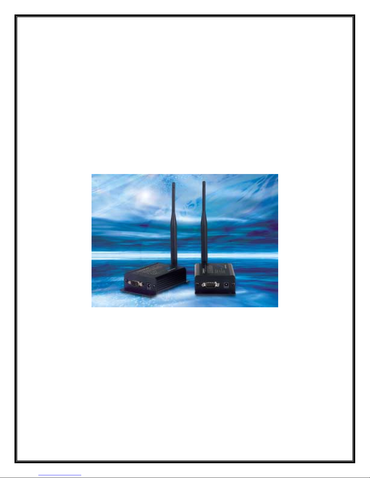
COMM-LINKS
comPPage
6801 Lake Worth Road – Suite 253 – Lake Worth, Florida 33467
Page 2
Limited Warranty, Disclaimer, Limitation of Liability
This product is warranted for a period of (1) year from date of purchase. comPPage warrants the COMM-LINKS against
defects in materials and workmanship. This warranty does not cover any damage or failure caused by misuse, abuse, acts
of God, accidents, electrical irregularity or other causes beyond comPPage’s control. The warranty will be void if there is
any evidence of tampering, repair or attempts to repair by anyone other than an comPPage authorized technician.
comPPage will not be liable for any damages arising from the use of this product, loss of use, revenue or profit of the
product.
After inspection, comPPage determines that there is a defect, comPPage will repair or replace the unit. When the unit is
replaced its warranty will be the reminder of the original unit sold.
Antenna Requirements
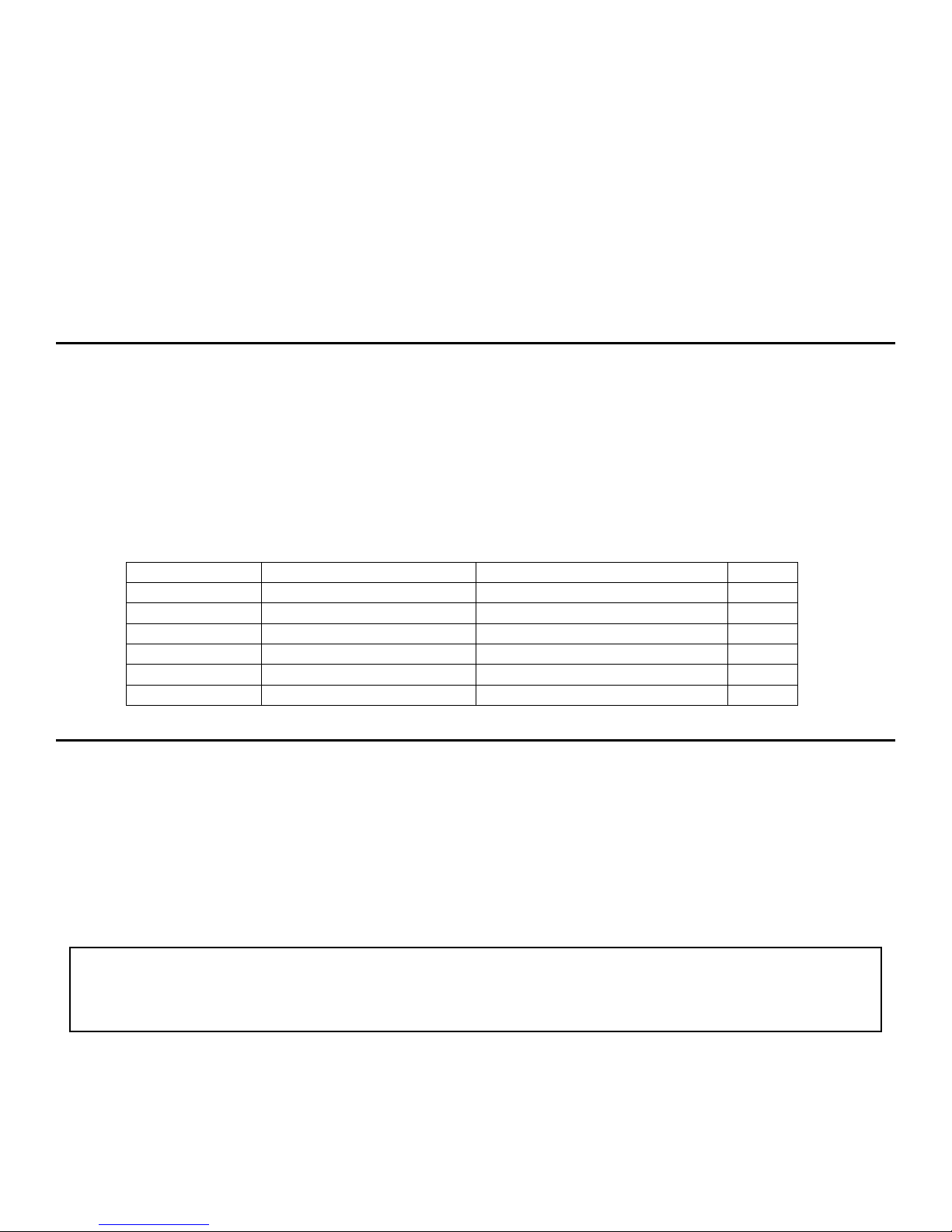
The COMM-LINKS has been tested with an MMCX connector with the antenna connected to the unit when sold. When
integrating the product any antenna not in the below listed table must be tested to comply with the FCC Section 15.203 for
Unique antenna connector and Section 15.247 for emissions.
Manufacturer Manufacture Part No. Type Gain(dBi)
Nearson S467FL-5-RMM-915S ½ Wave Dipole 2
Nearson S467FL-5-RMM-915 ½ Wave Dipole 2
Nearson S467AH-915S ½ Wave Dipole 2
Nearson S467AH-915 ½ Wave Dipole 2
Nearson S161AH-915R ½ Wave Dipole 2.5
Nearson S161AH-915 ½ Wave Dipole 2.5
Nearson S331AH-915 ¼ Wave Dipole 1
FCC Industry Canada (IC) Approvals
FCC – KQL-AC4490 IC – 2268C-44901000
This device complies with Part 15 of the FCC Rules. Operation is subject to the following two conditions.
(1) This device may not cause harmful interference, and (2) This device must accept nay interference received,
including interference that may cause undesired operation.
WARNING: This equipment has been approved for mobile applications where the equipment should be
Used at distances greater than 20cm from the human body (with the exceptions of hands,
Wrists, feet and ankles). Operation at distances less than 20cm is strictly prohibited.
2
Page 3

Overview
The RF RS232 COMM-LINKS is a cost-effective, high performance, frequency hopping spread spectrum transceiver.
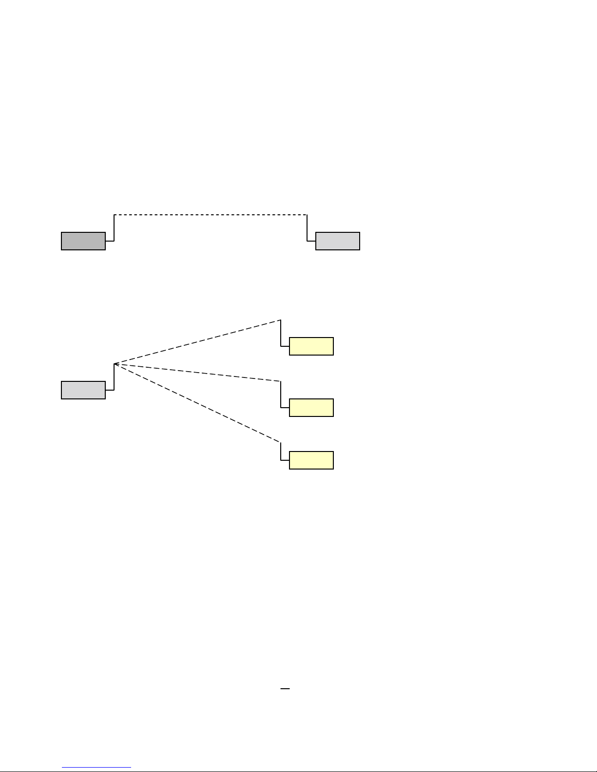
The transceivers operate in a Point-to-Point or Point-to-Multipoint, Client-Server or Peer-to-Peer architecture. One
transceiver is configured as a Server and there can be one or many Clients. To establish synchronization between
transceivers, the Server emits a beacon. Upon detecting a beacon, a Client transceiver informs its Host and a RF link
is established. All frequency hopping, synchronization, and RF system data transmission/reception is performed by the
transceiver.
When using Multi-networks in the same location, each network will have a different System ID and Channel ID.
All Client transceivers will be programmed for the channel ID and System ID of the Server they are to work with prior
to shipment. Configuration data is contained in an on-board EEPROM. These transceivers can be used as direct serial
cable replacements, requiring no special Host software for operations. These units are protocol independent.
Light Definitions
1. PWR – Green LED indicates power is connected to the unit.
2. LINK – Red LED indicates the Client Unit(s) and Server unit are in range of one another.
Link LED remains activated on Server units. Client units activate the Link LED when in range of the Server unit.
3. RX: - Green LED indicates when a COMM-LINKS unit is receiving data.
4. TX: - Red LED indicates when a COMM-LINKS unit is sending data.
Client/Server Definitions
In each network, there must be only one Server. All other COMM-LINKS units must be programmed as Clients. The
number of Clients in the network is not limited. However, if performance degrades, consider adding RF networks.
Networks
Up to 32 Independent networks can be created. The valid range of values for this is 16 to 47, Channel Numbers.
System Identification
The system number from 0 to 255 provides added security to each independent network of COMM-LINKS units. The
System ID is in conjunction with the Channel Number and serves as an RF password to maintain secure transfer of data.
The System ID and Channel Number must be unique to each network of COMM-LINKS to establish communications.
Additional security can be added when Data Encryption Key is added to the bit stream.
Serial Port
The Input of the Server and Output of the Client COMM-LINKS’ ports can be set for range of 1200 to 115,200 bps.
Units are shipped with a default setting of; 9600 n-8-1. Host equipment communications port must be set for the
following parameters. With these settings the data will not overrun the input buffer of the COMM-LINKS
Baud – 9600
Parity – none
Data Bits – 8
Stop Bits – 1
Flow Control – Hardware
Flow Control
For optimal performance, Hardware Flow Control is strongly recommended. If the Clear to Send (CTS) line is not used,
There is a chance that the transmit buffer will fill up to its maximum limit and data will be lost. Whenever CTS is High
the COMM-LINKS is not ready to receive additional data from the host. When CTS is low, COMM-LINKS is ready to
receive data.
3
Page 4

Acknowledge Mode
In Addressed Acknowledge Mode,(Point to Point) the RF packet is sent out to the receiver designated by the Destination
Address. Transmit Retries is used to increase the odds of a successful delivery to the intended receiver. Transparent to
the Host, the sending transceiver will send the RF packet to the intended receiver. If the receiver receives the packet free
of errors, it will tell the sender. If the sender does not receive this acknowledge, it will assume the packet was never
received and retry the packet.
In Broadcast Acknowledge Mode, (Point to Multipoint
network. Broadcast Attempts is used to increase the odds of successful delivery to the intended receiver(s). If the
receiver detects a packet error, it will throw out the packet. This will go on until the packet is successfully received or the
transmitter exhausts all of its attempts. Once the receiver successfully receives the packet it will send the packet to the
Host. It will throw out any duplicates caused by further Broadcast Attempts.
) the RF packet is broadcast out to all eligible receivers on the
Server Installation
1. Mount the COMM-LINKS marked [SERVER] near the Host equipment.
2. Connect the COMM-LINKS marked [SERVER] to the host equipment using the supplied 9 Pin serial cable.
3. Attach the antenna to the COMM-LINKS.
4. Connect the AC wall adapter to a 115 Volt AC outlet and attach to the COMM-LINKS.
5. Check to ensure the [LINK] and [POWER] light is ON.
Client Installation
1. Mount the COMM-LINKS marked [CLIENT] near the paging equipment.
2. Connect the COMM-LINKS marked [CLIENT] to the paging equipment using the supplied 9 Pin serial cable.
3. Attach the antenna to the COMM-LINKS.
4. Connect the AC wall adapter to a 115 Volt AC outlet and attach to the COMM-LINKS.
5. Check to ensure the [LINK] and [POWER] light is ON.
6. If the [LINK] light is not ON, the SERVER may be off line or the CLIENT is out of range of the SERVER.
4
Page 5
Troubleshooting
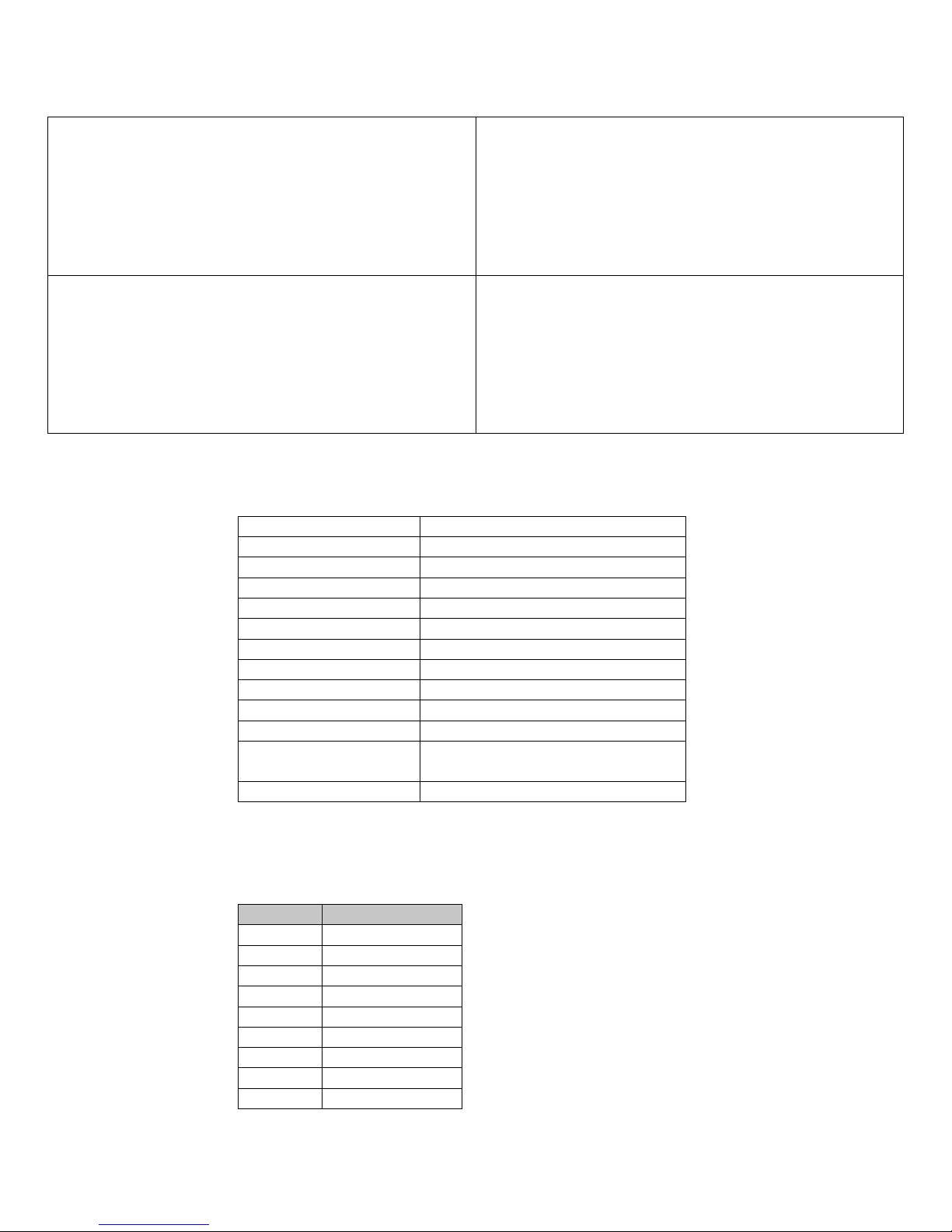
Problem Solution
Client’s Link LED does not come on. 1. Make sure Server COMM-LINKS unit is connected
to power.
2. Cycle power to both COMM-LINKS units.
3. Check programming sheet to ensure Client is
programmed for Server on network. Same
System ID and Channel No.
4. Client may be out of Range of the Server.
Link LED is on, but data does not get transmitted or
received.
1. Make sure the COMM-LINKS unit(s) is connected
to the correct COM port.
2. Check COM port settings for correct Baud Rate,
Parity and either Hardware or No Flow Control.
Units can have transmission errors with Flow
Control set to Xon/Xoff.
3. Connect a Null Modem adapter between the Client
And its host device.
Specifications
Dimensions 4.4 x 2.7 x 1.4 Inches
Weight 6.0z (170 g)
Serial Cable 6 feet
Interface RS232
Connector DB9 Male
RF Output 750mW (1 Watt ERP)
Antenna ½ Wave Dipole 2.5 dBi
Mode FHSS
Frequency 902-928 Mhz
Power 700 mA, 6-18VDC
Electrical 100-120AC 60Hz
Range Up to 1500 Feet indoors
Up to 20 Miles line of slight
Environment -40º to +80º C
Cable Pin out Definition
Standard RS232 DB9 Female connector, pin to pin. (Black DB9 Female/Female Cable)
Pin Description
1 DCD
2 RxD
3 TxD
4 DTR
5 GND
6 DSR
7 RTS
8 CTS
9 RI
5
Page 6
t
t
t
t
RF Architectures
Point to Point
Clien
Sever
Clien
Clien
Point to Multipoint
Clien
6
 Loading...