

Page 1
Page 1 of 28
INSTRUCTION MANUAL
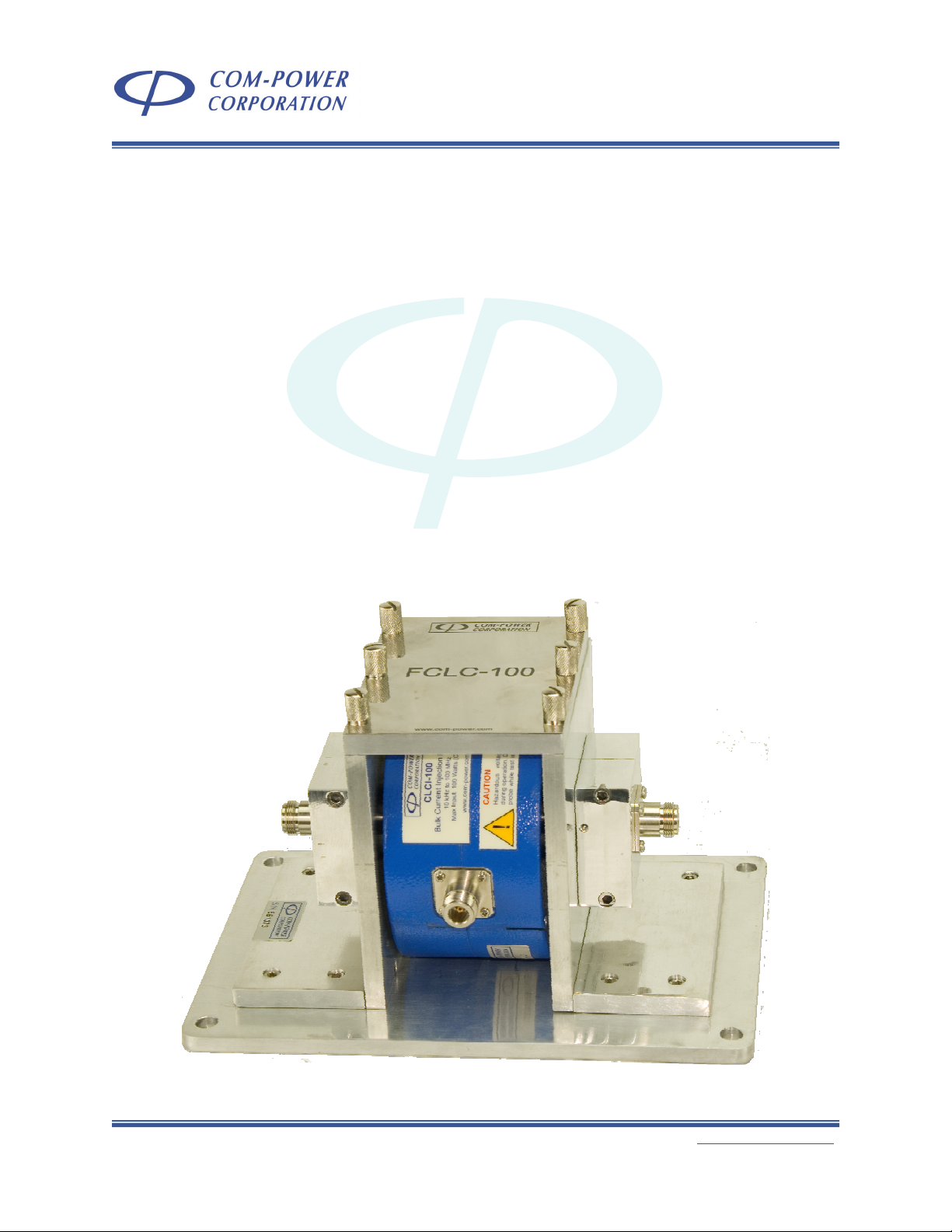
CLCI-100 BULK CURRENT INJECTION PROBE
with FCLC-100 CALIBRATION FIXTURE
INSTRUCTION MANUAL
For
BULK CURRENT
INJECTION PROBE
Model: CLCI-100
and
CALIBRATION FIXTURE
Model: FCLC-100
(optional)
19121 El Toro Rd ● Silverado, California 92676 ● (949) 459-9600 ● com-power.com
REV051917
Page 2

Page 2 of 28
INSTRUCTION MANUAL
CLCI-100 BULK CURRENT INJECTION PROBE
with FCLC-100 CALIBRATION FIXTURE
Table of Contents
1.0 Introduction ........................................................................................................... 4
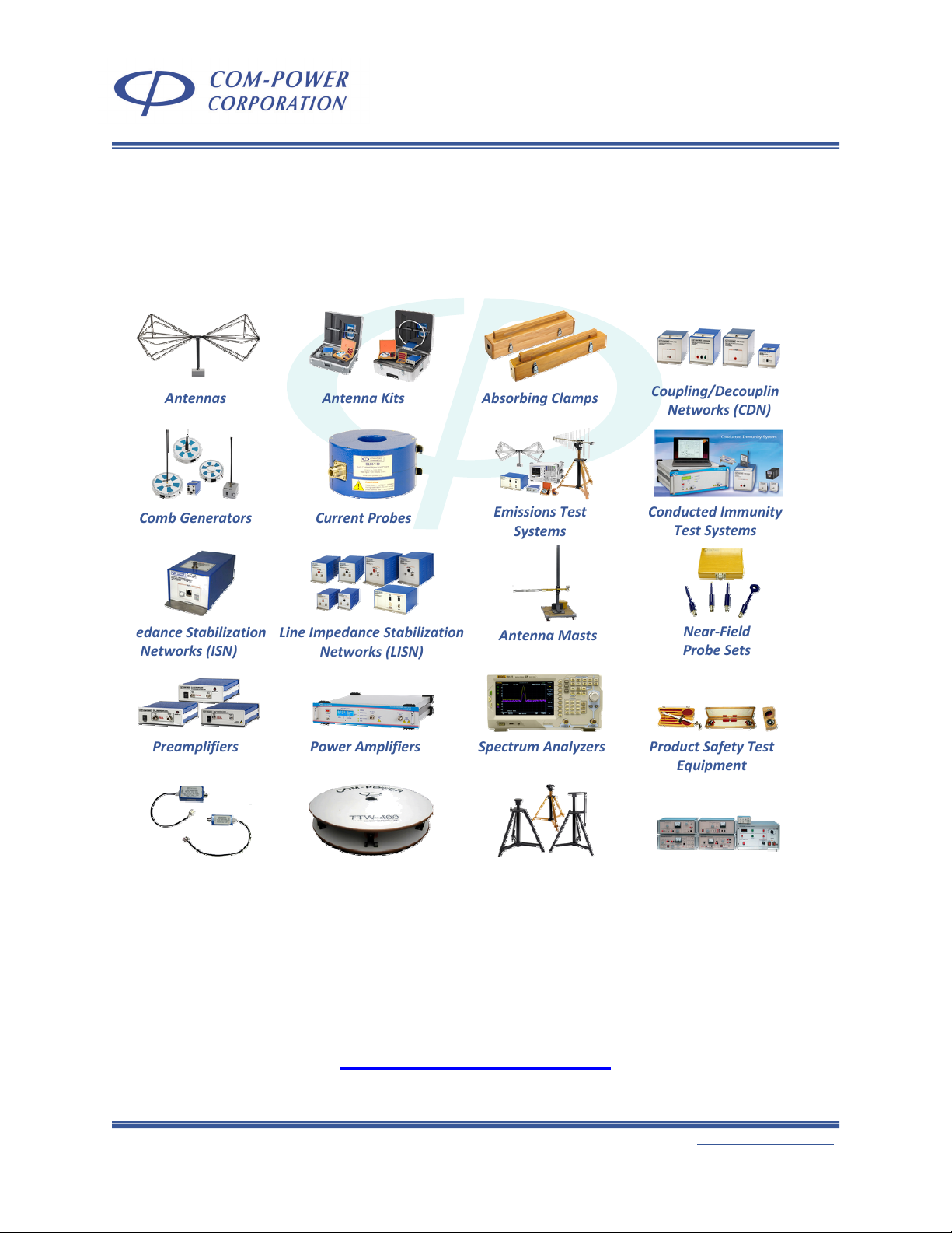
2.0 Products Available from Com-Power ................................................................. 5
3.0 Product Information .............................................................................................. 6
3.1 Incoming Inspection ....................................................................................................... 6
3.2 Package Inventory ......................................................................................................... 6
3.3 Product Safety Information ........................................................................................... 7
3.3.1 Product Hazard Symbols Definitions........................................................................................... 7
3.3.2 Product Warning/Caution Statements...................................................................................... 7
3.3.3 General Safety Instructions .......................................................................................................... 7
3.4 Product Features ............................................................................................................. 8
3.4.1 Description of CLCI-100 Bulk Current Injection Probe Features ............................................ 8
3.4.2 Description of FCLC-100 Calibration Fixture Features............................................................. 9
3.5 Product Specifications ................................................................................................. 10
3.5.1 Specifications for CLCI-100 Bulk Current Injection Probe..................................................... 10
3.5.2 Specifications for FCLC-100 Calibration Fixture ..................................................................... 10
3.6 Product Dimensional Diagrams .................................................................................. 11
3.6.1 Dimensions of CLCI-100 Bulk Current Injection Probe........................................................... 11
3.6.2 Dimensions of FCLC-100 Calibration Fixture ........................................................................... 12
4.0 Using the CLCI-100 Probe with the FCLC-100 Fixture....................................... 13
4.1 Installation of CLCI-100 Probe into FCLC-100 Fixture ............................................. 13
4.2 Insertion Loss/Coupling Factor Measurement.......................................................... 14
4.3 Transfer Impedance Factors .......................................................................................15
4.4 Conducted Immunity Test Level Calibration (IEC 61000-4-6) ................................ 16
4.4.1 Test Generator Equipment (Method A vs Method B) ........................................................... 16
4.4.2 Calibration-related Calculations .............................................................................................. 18
4.4.2.1 Test Level Calculations ............................................................................................................... 18
4.4.2.2 Test Level Offset Calculations ................................................................................................... 19
4.4.2.3 Test Frequency Calculations .....................................................................................................19
4.4.3 Equipment Setup ......................................................................................................................... 20
4.4.4 Level Setting Process................................................................................................................... 22
4.4.5 Amplifier Saturation Check........................................................................................................ 23
4.4.6 Running the Test .......................................................................................................................... 24
4.5 Conducted Susceptibility Test Level Calibration (50Ω System)............................. 26
5.0 Warranty............................................................................................................... 27
6.0 Typical CLCI-100 Calibration Data.................................................................... 28
19121 El Toro Rd ● Silverado, California 92676 ● (949) 459-9600 ● com-power.com
REV051917
Page 3

Page 3 of 28
INSTRUCTION MANUAL
CLCI-100 BULK CURRENT INJECTION PROBE
with FCLC-100 CALIBRATION FIXTURE
List of Figures
FIGURE 1 - CLCI-100 Bulk Current Injection Probe Features 8
FIGURE 2 - FCLC-100 Calibration Fixture Features 9
FIGURE 3 - Dimensional Diagram for CLCI-100 Bulk Current Injection Probe 11
FIGURE 4 - Dimensional Diagram for FCLC-100 Calibration Fixture 12
FIGURE 5 - Installation of CLCI-100 Probe into FCLC Calibration Fixture 13
FIGURE 6 - Setup for Insertion/Coupling Loss in a 50Ω System (100Ω Loop) 14
FIGURE 7 - Setup for Insertion/Coupling Loss in a 150Ω System (300Ω Loop) 14
FIGURE 8 - Equivalent Schematic of Calibration Circuit 15
FIGURE 9 - Examples of Test Generator Systems 16
FIGURE 10 - Setup for Calibration Accessories for 150Ω System 20
FIGURE 11 - IEC 61000-4-6 (Method A) Test Level Calibration Setup 20
FIGURE 12 - IEC 61000-4-6 (Method B) Test Level Calibration Setup 21
FIGURE 13 - IEC 61000-4-6 (Method A) Test Setup 24
FIGURE 14 - IEC 61000-4-6 (Method B) Test Setup 25
FIGURE 15 - Test Level Calibration into 50 ohm System 26
19121 El Toro Rd ● Silverado, California 92676 ● (949) 459-9600 ● com-power.com
REV051917
Page 4

Page 4 of 28
1.0 Introduction
This manual includes descriptions of the CLCI-100 Bulk Current Injection Probe
connections, product specifications, safety precautions, operational instructions,
calibration instructions, measurement guidelines and warranty information.
Information contained in this manual is the property of Com-Power Corporation. It is
issued with the understanding that the material may not be reproduced or copied
without the express written permission of Com-Power.
INSTRUCTION MANUAL
CLCI-100 BULK CURRENT INJECTION PROBE
with FCLC-100 CALIBRATION FIXTURE
19121 El Toro Rd ● Silverado, California 92676 ● (949) 459-9600 ● com-power.com
REV051917
Page 5
Page 5 of 28
d
S
CLCI-100 BULK CURRENT INJECTION PROBE
with FCLC-100 CALIBRATION FIXTURE
2.0 Products Available from Com-Power
Antennas
AntennaKits AbsorbingClamps
INSTRUCTION MANUAL
Coupling/Decoupling
Networks(CDN)
CombGenerators
ImpedanceStabilization
Networks(ISN)
Preamplifiers
TransientLimiters
CurrentProbes
LineImpedanceStabilization
Networks(LISN)
PowerAmplifiers
Turntables
EmissionsTest
Systems
AntennaMasts
pectrumAnalyzers
AntennaTripods
ConductedImmunity
TestSystems
Near‐Fiel
ProbeSets
ProductSafetyTest
Equipment
TelecomTest
Systems
www.com-power.com
19121 El Toro Rd ● Silverado, California 92676 ● (949) 459-9600 ● com-power.com
REV051917
Page 6

Page 6 of 28
3.0 Product Information
3.1 Incoming Inspection
If there is any evidence of shipping damage. If shipping damage to the product
or any of its accessories is suspected, or if the package contents are not
complete, contact Com-Power or your Com-Power distributor.
Please check the contents of the shipment against the package inventory in
section 3.2 to ensure that you have received all applicable items.
3.2 Package Inventory
STANDARD ITEMS:
9
CLCI-100 Bulk Current Injection Probe
9 Calibration Certificate and Associated Data
OTIONAL ITEMS:
9
FCLC-100 Calibration Fixture
9 ADA-515-2 150Ω to 50Ω Adapter Set
9 ATTN-06-100W Power Attenuator (6 dB, 100W)
9 ATTN-30-100W Power Attenuator (30 dB, 100W)
9 TERM-100W Termination (50Ω)
9 DCD-1000-100W Dual Directional Coupler
INSTRUCTION MANUAL
CLCI-100 BULK CURRENT INJECTION PROBE
with FCLC-100 CALIBRATION FIXTURE
19121 El Toro Rd ● Silverado, California 92676 ● (949) 459-9600 ● com-power.com
REV051917
Page 7
Page 7 of 28
INSTRUCTION MANUAL
CLCI-100 BULK CURRENT INJECTION PROBE
with FCLC-100 CALIBRATION FIXTURE
3.3 Product Safety Information
3.3.1 Product Hazard Symbols Definitions
The hazard symbols appearing on the product exterior are defined below.
The yellow triangle with an exclamation mark indicates the presence of
important operating and/or maintenance (servicing) instructions in the
literature accompanying the product.
3.3.2 Product Warning/Caution Statements
CAUTION: Hazardous voltages present during operation. Do not handle probe while test is in
progress.
3.3.3 General Safety Instructions
The following safety instructions have been included in compliance with safety standard
regulations. Please read them carefully.
• READ AND RETAIN INSTRUCTIONS - Read all safety and operating instructions before
operating the instrument. Retain all instructions for future reference.
• HEED WARNINGS - Adhere to all warnings on the instrument and operating instructions.
• FOLLOW INSTRUCTIONS - Follow all operating and use instructions.
• WATER AND MOISTURE - Do not use the instrument near water.
• WALL OR CEILING MOUNTING - Do not mount the instrument on a wall or ceiling.
• HEAT - The instrument should be situated away from heat sources such as heat registers or
other instruments which produce heat.
• POWER SOURCES - Connect the instrument only to the type of power source described in
the operating instructions or as marked on the instrument.
• POWER CORD PROTECTION - Place power supply cords so that they are not likely to be
walked on or pinched by items placed on them or against them.
• CLEANING – Clean the instrument only as recommended by the manufacturer.
• DEFECTS AND ABNORMAL STRESS - Whenever it is likely that the normal operation has been
impaired, make the equipment inoperable and secure it against further operation.
• DAMAGE REQUIRING SERVICE - Instrument should be serviced by qualified personnel when:
9 The power supply cord or the plug has been damaged.
9 Objects have fallen or liquid has been spilled into the instrument.
9 The instrument has been exposed to rain.
9 The instrument does not appear to operate normally.
9 The instrument has been dropped, or the enclosure has been damaged.
• SITTING OR CLIMBING - Do not sit or climb upon the instrument or use it as a step or ladder.
19121 El Toro Rd ● Silverado, California 92676 ● (949) 459-9600 ● com-power.com
REV051917
Page 8
Page 8 of 28
INSTRUCTION MANUAL
CLCI-100 BULK CURRENT INJECTION PROBE
with FCLC-100 CALIBRATION FIXTURE
3.4 Product Features
3.4.1 Description of CLCI-100 Bulk Current Injection Probe Features
1
(clamp closed)
SIDE VIEW
CLCI-100
Bulk Current Injection Probe
10 kHz to 100 MHz
Max Input: 100 Watts (CW)
www.com-power.com
CAUTION
Hazardous voltages present
during operation. Do not handle
probe while test is in progress.
TOP VIEW
2
(clamp open)
3
1
4
1
2
3
3
4
3
3
4
FIGURE 1 - CLCI-100 Bulk Current Injection Probe Features
Input/Output Port
1
When used for bulk current injection, this is the input port of the probe. When used as a
measuring device, this is the probe’s output port. It is fitted with an N-type coaxial
connector.
Spring-loaded Clasps
2
These two (2) clasps, when secured over their respective brackets, lock the clamp into its
closed position
Clasp Brackets
3
These two (2) brackets anchor the respective clasp brackets in order to lock the clamp into
its closed position.
Clamp Window
4
This clamp window is aperture in the center of the clamp through which the wire(s),
cable(s) or cable bundle(s) to be tested are passed through.
2
19121 El Toro Rd ● Silverado, California 92676 ● (949) 459-9600 ● com-power.com
REV051917
Page 9
Page 9 of 28
INSTRUCTION MANUAL
CLCI-100 BULK CURRENT INJECTION PROBE
with FCLC-100 CALIBRATION FIXTURE
3.4.2 Description of FCLC-100 Calibration Fixture Features
4
5
4
3
2
1
3
3
4
FCLC-100
4
www.com-power.com
4
4
FIGURE 2 - FCLC-100 Calibration Fixture Features
Fixture Opening
1
The CLCI-100 is installed within this opening so that the center conductor rod of the fixture
passes through the approximate center of the probe aperture.
Center Conductor Rod
2
This is the fixture’s center conductor.
Calibration Fixture Coaxial Ports
3
These are female N-type coaxial connectors providing input/output connections to the
fixture.
Thumb Screws for Removable Top Plate
4
These (6) screws secure the fixture’s top plate to the fixture assembly.
Removable Top Plate of Fixture
5
In order to install/remove the clamp into/from the calibration fixture, the top plate must be
removed by removing the six (6) thumb screws. The top cover and thumb screws must be
replaced prior to the performance of tests.
3
19121 El Toro Rd ● Silverado, California 92676 ● (949) 459-9600 ● com-power.com
REV051917
Page 10

Page 10 of 28
INSTRUCTION MANUAL
CLCI-100 BULK CURRENT INJECTION PROBE
with FCLC-100 CALIBRATION FIXTURE
3.5 Product Specifications
3.5.1 Specifications for CLCI-100 Bulk Current Injection Probe
Technical
Transfer Impedance Factors see graph(s) located in Section 6
Product
Model
Frequency Range
Standard(s) IEC 61000-4-6, MIL-STD 461x, RTCA-DO-160x, etc
Impedance
Maximum Input Power
Bulk Current Injection Probe
CLCI-100
10 kHz to 100 MHz
50Ω (nominal)
100 Watts (continuous)
Mechanical
Coaxial RF Connector
Dimensions (H)x(W)x(L)
Probe Aperture Diameter
Weight
N-type (female)
5” x 2.75” x 5.78”
1.575”
(4 cm)
4.5 lbs (2.04 kg)
(12.75 x 7 x 14.7 cm)
Environmental
Operating Temperature
40°F to 104°F (5°C to 40°C)
3.5.2 Specifications for FCLC-100 Calibration Fixture
Technical
Product
Model
Frequency Range
Standard(s) IEC 61000-4-6, MIL-STD 461x, RTCA-DO-160x, etc
Impedance
VSWR
(empty fixture –
no probe installed)
Calibration Fixture
FCLC-100
10 kHz to 100 MHz
50Ω (nominal)
0.01-2.5 MHz
2.5-10 MHz
10-30 MHz
30-100 MHz ≤ 1.4 : 1
≤ 1.01 : 1
≤ 1.04 : 1
≤ 1.1 : 1
Mechanical
Coaxial RF Connectors
Dimensions (H)x(W)x(L)
Weight (empty fixture)
(2) N-type (female)
6.4” x 7” x 10”
(16.3 x 17.8 x 25.5 cm)
8 lbs. (3.63 kg)
Dimensional Accommodations for Current Probes
Max. Probe Diameter
Min. Probe Aperture Diameter
Max. Probe Width
5.63” (14.3 cm)
0.79” (2 cm)
2.83” (7.2 cm)
Environmental
Operating Temperature
19121 El Toro Rd ● Silverado, California 92676 ● (949) 459-9600 ● com-power.com
40°F to 104°F (5°C to 40°C)
REV051917
Page 11

Page 11 of 28
INSTRUCTION MANUAL
CLCI-100 BULK CURRENT INJECTION PROBE
with FCLC-100 CALIBRATION FIXTURE
3.6 Product Dimensional Diagrams
3.6.1 Dimensions of CLCI-100 Bulk Current Injection Probe
(7 cm)
(12.75 cm)
(W)
2.75”
(H)
5”
CLCI-100
Bulk Current Injection Probe
10 kHz to 100 MHz
Max Input: 100 Watts (CW)
www.com-power.com
CAUTION
Hazardous voltages present
during operation. Do not handle
probe while test is in progress.
TOP VIEW
SIDE VIEW
1.57”
(4 cm)
(L)
5.78”
(14.7 cm)
FIGURE 3 - Dimensional Diagram for CLCI-100 Bulk Current Injection Probe
19121 El Toro Rd ● Silverado, California 92676 ● (949) 459-9600 ● com-power.com
REV051917
Page 12

Page 12 of 28
INSTRUCTION MANUAL
CLCI-100 BULK CURRENT INJECTION PROBE
with FCLC-100 CALIBRATION FIXTURE
3.6.2 Dimensions of FCLC-100 Calibration Fixture
(W)
(17.8 cm)
7”
FCLC-100
(H)
6.4”
(16.3 cm)
www.com-power.com
TOP VIEW
SIDE VIEW
5”
(12.8 cm)
2.95”
(7.5 cm)
(L)
10”
(25.5 cm)
FIGURE 4 - Dimensional Diagram for FCLC-100 Calibration Fixture
19121 El Toro Rd ● Silverado, California 92676 ● (949) 459-9600 ● com-power.com
REV051917
Page 13

Page 13 of 28
INSTRUCTION MANUAL
CLCI-100 BULK CURRENT INJECTION PROBE
with FCLC-100 CALIBRATION FIXTURE
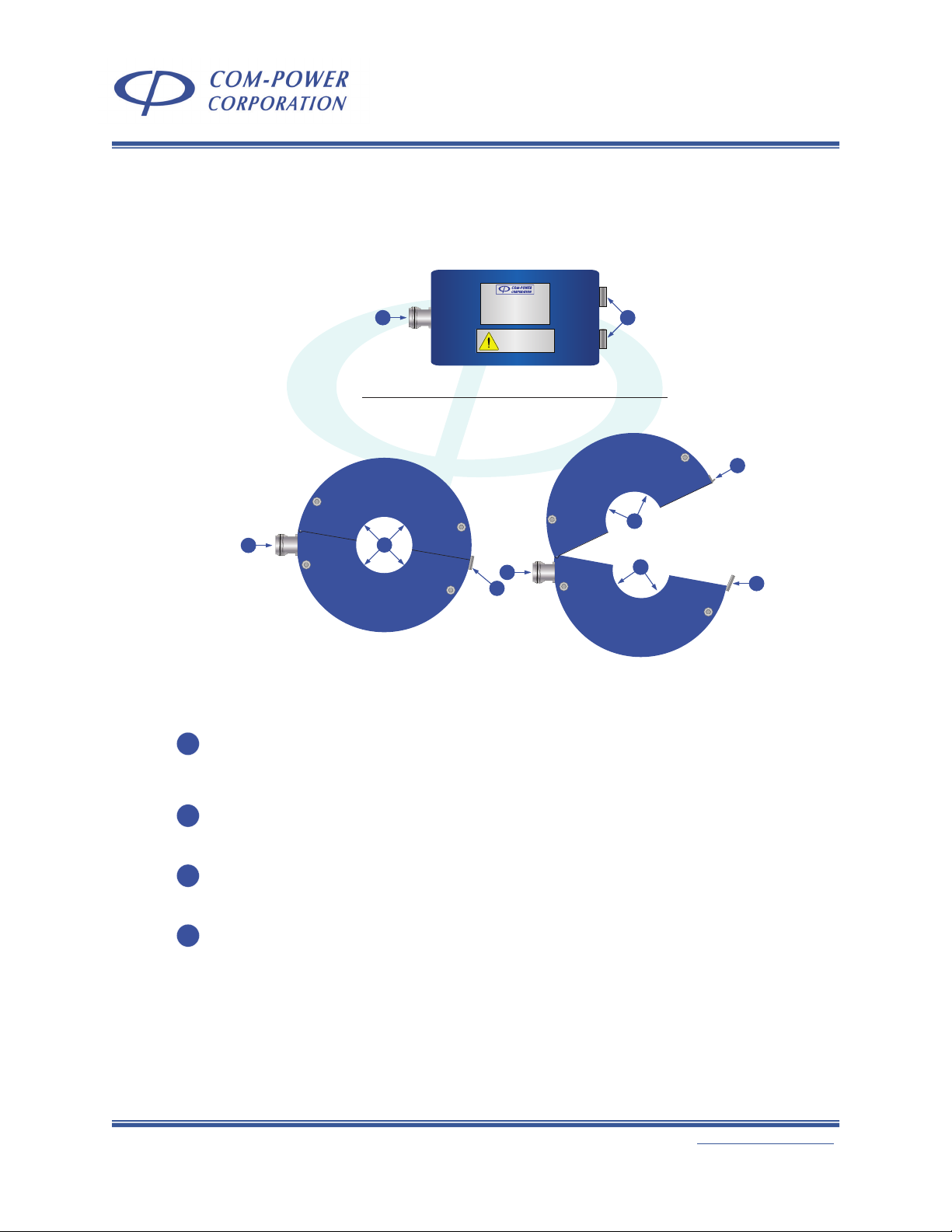
4.0 Using the CLCI-100 Probe with the FCLC-100 Fixture
Calibration fixtures provide a means by which current probes, including bulk current
injection (BCI) probes, can be calibrated to determine the transfer impedance,
insertion/coupling loss. Fixtures are also used to establish, or calibrate, power drive levels
into 50Ω or 150Ω systems for various conducted susceptibility/immunity tests performed
using BCI probes. These applications are discussed in more detail in the following
sections.
The FCLC-100 Fixture is specifically designed for use with the CLCI-100 BCI probe. The
intent of the fixture is to maintain the coaxial structure of the transmission line, while
allowing the probe to be installed around the center conductor of the coaxial line.
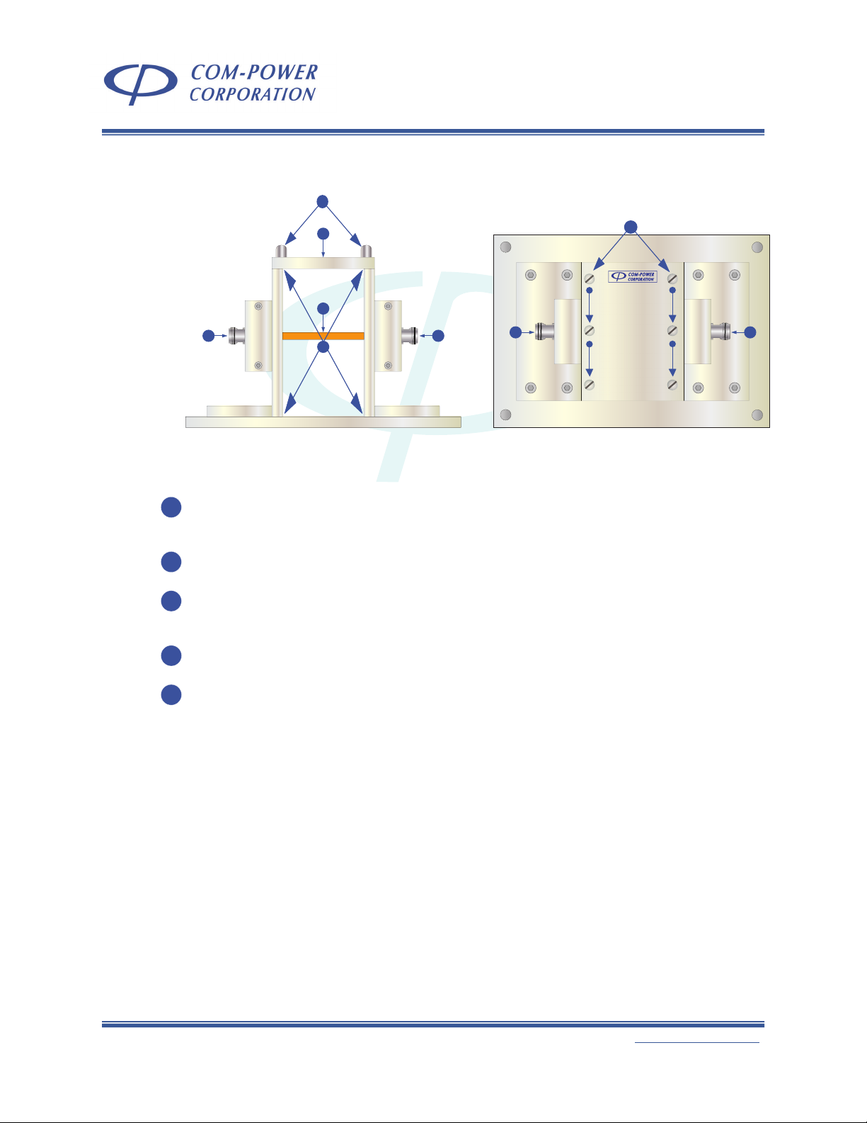
4.1 Installation of CLCI-100 Probe into FCLC-100 Fixture
Illustrated in Figure 5 is the procedure to be followed for installing the CLCI-100 BCI
Probe into the FCLC Calibration Fixture.
STEP 1
UNSCREW SIX (6)
THUMBSCREWS
ON TOP OF
FIXTURE AND
REMOVE
TOP PLATE
STEP 2
OPEN CLAMP
AS SHOWN ABOVE
AND LOWER
CLAMP INTO
CENTER OF
FIXTURE
STEP 3
ROTATE CLAMP
APPROX. 90
DEGREES, SO THAT
PROBE’S RF
CONNECTOR FACES
OUTWARD ON EITHER
OPEN SIDE OF
THE FIXTURE
STEP 4
CLOSE PROBE
AROUND FIXTURE
CENTER
CONDUCTOR,
HOOK BOTH
SPRING-LOADED
CLASPS ONTO
RESPECTIVE
BRACKETS AND
LOCK CLASPS
STEP 5
REPLACE TOP
PLATE OF
TEST
FIXTURE
STEP 6
REPLACE AND
TIGHTEN THE SIX (6)
THUMBSCREWS
FIGURE 5 - Installation of CLCI-100 Probe into FCLC Calibration Fixture
19121 El Toro Rd ● Silverado, California 92676 ● (949) 459-9600 ● com-power.com
REV051917
Page 14

Page 14 of 28
C
00
kH
kHz
t
to
10
10
0M
0 M
H
Hz
put
(CW
)
com
po
er
com
ON
d
l
t
op
e
g
.
C
00
kH
kHz
t
to
10
10
0M
0 M
H
Hz
put
(CW
)
com
po
er
com
ON
d
l
t
op
e
g
.
INSTRUCTION MANUAL
CLCI-100 BULK CURRENT INJECTION PROBE
with FCLC-100 CALIBRATION FIXTURE
4.2 Insertion Loss/Coupling Factor Measurement
Illustrated in Figures 6 and 7 are typical setups for the measurement of a current
probe’s insertion loss, also known as coupling factor. Figure 6 shows the setup for
a 50 ohm system (100 ohm loop); and Figure 7 shows the setup for a 150 ohm
system (300 ohm loop).
The insertion loss/coupling factor is essentially the difference between the voltage
present on the conductor(s) passing through the current probe aperture and the
voltage present at the output of the probe. These two quantities are depicted as
and V2, respectively, in Figure 8; where V2 - V1= Insertion Loss/Coupling Factor.
V
1
Network Analyzer
with
S-Parameter Capabilities
- or -
Spectrum Analyzer/EMI Receiver
with
Tracking Generator
- or -
Synthesized Signal Generator
and
Spectrum Analyzer/Receiver
RF
OUTPUT
RF
INPUT
Network Analyzer
with
S-Parameter Capabilities
- or -
Spectrum Analyzer/EMI Receiver
with
Tracking Generator
- or -
Synthesized Signal Generator
and
Spectrum Analyzer/Receiver
RF
OUTPUT
RF
INPUT
CLCI-100
10 kHz to 100 MHz
www.com-power.com
Max Input: 100 Watts (CW)
Bulk Current Injection Probe
FRONT VIEW
TOP VIEW
CAUTION
Hazardous voltages present
during operation. Do not handle
probe while test is in progress.
ress
.
tages presen
w
eration. Do not handl
I-1
-
10 dB
10 dB
10 dB
GROUND PLANE
FCLC-100
: 100 Watts
L
CLCI-100
10 kHz to 100 MHz
www.com-power.com
www.
Max Input: 100 Watts (CW)
Max In
Bulk Current Injection Probe
Bulk Current Injection Probe
www.com-power.com
10 dB
ous vo
AUTI
ur
azar
CAUTION
Hazardous voltages present
during operation. Do not handle
probe while test is in progress.
probe while test is in pro
50Ω
NORMALIZATION CALIBRATION - 50Ω SYSTEM (100Ω LOOP)
FIGURE 6 - Setup for Insertion/Coupling Loss in a 50Ω System (100Ω Loop)
Network Analyzer
with
S-Parameter Capabilities
- or -
Spectrum Analyzer/EMI Receiver
with
Tracking Generator
- or -
Synthesized Signal Generator
and
Spectrum Analyzer/Receiver
RF
OUTPUT
RF
INPUT
10 dB
10 dB
Network Analyzer
with
S-Parameter Capabilities
- or -
Spectrum Analyzer/EMI Receiver
with
Tracking Generator
- or -
Synthesized Signal Generator
and
Spectrum Analyzer/Receiver
RF
OUTPUT
RF
INPUT
ADA-
10 dB
515-2
GROUND PLANE
CLCI-100
10 kHz to 100 MHz
www.com-power.com
Max Input: 100 Watts (CW)
Bulk Current Injection Probe
FRONT VIEW
TOP VIEW
.
w
I-1
-
FCLC-100
: 100 Watts
L
CLCI-100
10 kHz to 100 MHz
www.com-power.com
www.
Max In
Max Input: 100 Watts (CW)
Bulk Current Injection Probe
Bulk Current Injection Probe
www.com-power.com
10 dB
CAUTION
Hazardous voltages present
during operation. Do not handle
probe while test is in progress.
ress
tages presen
eration. Do not handl
ous vo
AUTI
ur
azar
CAUTION
Hazardous voltages present
during operation. Do not handle
probe while test is in progress.
probe while test is in pro
ADA515-2
50Ω
NORMALIZATION CALIBRATION -150Ω SYSTEM (300Ω LOOP)
FIGURE 7 - Setup for Insertion/Coupling Loss in a 150Ω System (300Ω Loop)
19121 El Toro Rd ● Silverado, California 92676 ● (949) 459-9600 ● com-power.com
REV051917
Page 15

Page 15 of 28
V
1
I
P
V
2
Z
T
= Transfer Impedance (in dBΩ)Ω)
V
1
= RF voltage on the coaxial line (in dBμV)
V
2
= RF output voltage of the probe in (in dBμV)
I
P
= measured current (in dBμA)
34
= dB ratio between voltage and current in a 50
Ω system
= 20*log(50Ω)
where:
Z
TV2
I
P
= -
L
ins
= Insertion Loss/Coupling Loss (in dB)
34L
ins
Z
T
= +
V
1
V
2
L
ins
= -
INSTRUCTION MANUAL
CLCI-100 BULK CURRENT INJECTION PROBE
with FCLC-100 CALIBRATION FIXTURE
4.3 Transfer Impedance Factors
When performing current measurements, the conductor(s) under test are passed
through the aperture of the current probe. The RF port of the current probe is
connected to the 50 ohm RF input of a spectrum analyzer or EMI receiver, where
a voltage value is measured.
The transfer impedance factor includes the loss of the probe (see section 4.2),
and also converts the measured voltage value to a current value corresponding
to the current flowing on the conductor(s) under test.
Illustrated in Figure 8 is a diagram of the equivalent calibration circuit, along with
the associated calculations.
50Ω
probe while test is in progress.
CAUTION
Hazardous voltages present
during operation. Do not handle
Bulk Current Injection Probe
Max Input: 100 Watts (CW)
www.com-power.com
10 kHz to 100 MHz
CLCI-100
50Ω
50Ω
ins
34
ins
where:
= Transfer Impedance (in dB
= Insertion Loss/Coupling Loss (in dB)
ins
= RF voltage on the coaxial line (in dBμV)
= RF output voltage of the probe in (in dBμV)
= dB ratio between voltage and current in a 50
34
= 20*log(50Ω)
= measured current (in dBμA)
FIGURE 8 - Equivalent Schematic of Calibration Circuit
Ω system
19121 El Toro Rd ● Silverado, California 92676 ● (949) 459-9600 ● com-power.com
REV051917
Page 16

Page 16 of 28
INPUT
INSTRUCTION MANUAL
CLCI-100 BULK CURRENT INJECTION PROBE
with FCLC-100 CALIBRATION FIXTURE
4.4 Conducted Immunity Test Level Calibration (IEC 61000-4-6)
Calibration of test levels per IEC 61000-4-6 is performed with the CLCI-100 Bulk
Current Injection Probe installed in the FCLC-100 Calibration Fixture. The
calibration is performed into a 150 ohm system, rather than the standard 50 ohm
system employed by other standards, such as Mil-Std 461 and RTCA DO-160.
To realize a 150 ohm system, ADA-515-2 150Ω to 50Ω Adapters are installed on
either side of the test fixture.
4.4.1 Test Generator Equipment (Method A vs Method B)
Per the IEC 61000-4-6 standard, there are two acceptable procedures for
quantifying the Test Generator power when the appropriate test level is
measured during the calibration at any given frequency, so that the same
level can be reproduced during the actual testing process. For the
purposes of this procedure, we will refer to these as METHOD A (Signal
Generator Output Method) and METHOD B (Forward Power Method).
Illustrated in Figure 9 are example diagrams of the respective test
generator systems.
OUTPUT
RF POWER
METER
POWER
AMPLIFIER
INPUT OUTPUT
PWR SENSOR
6 dB Attenuator
to ...
RF Port
of BCI
Probe
SIGNAL
GENERATOR
OUTPUT
POWER
AMPLIFIER
INPUT OUTPUT
6 dB Attenuator
to ...
RF Port
of BCI
Probe
SIGNAL
GENERATOR
FIGURE 9a -
EXAMPLE OF TEST GENERATOR EQUIPMENT
METHOD A
(Signal Gen. Output Method)
FIGURE 9b -
EXAMPLE OF TEST GENERATOR EQUIPMENT
METHOD B
(Forward Power Method)
FIGURE 9 - Examples of Test Generator Systems
For each method, the RF power is injected into RF port of the bulk current
injection probe, and the amplitude is measured at the output of the 150Ω
to 50Ω Adapter (ADA-515-2) connected to one side of the test fixture
(through a power attenuator). For each test frequency, the amplitude of
the injected RF is adjusted incrementally until the measured amplitude
reaches the appropriate level (U
mr
).
19121 El Toro Rd ● Silverado, California 92676 ● (949) 459-9600 ● com-power.com
REV051917
Page 17

Page 17 of 28
INSTRUCTION MANUAL
CLCI-100 BULK CURRENT INJECTION PROBE
with FCLC-100 CALIBRATION FIXTURE
Method A: For method A, once the appropriate amplitude is
measured during calibration process, the signal
generator output level is recorded with respect to the
test frequency.
During the test, the signal generator output level at any
given test frequency is equal to the respective signal
generator output level recorded during the calibration.
Method B: For method B, once the appropriate amplitude is
measured during the calibration process, the forward
power of the test generator is recorded. The forward
power is measured with an RF power meter and power
sensor, typically connected to the forward port of a
directional coupler installed in series with the RF output
of the power amplifier.
During the test, the signal generator output level is
adjusted so that the forward power measured on the
power meter at any given frequency is equal to the
respective forward power level recorded during the
calibration.
In the following sections, instructions are included for both methods:
Instructions common for both METHOD A and METHOD B are shown in
BLACK text.
Any instructions which apply only for METHOD A are shown in GREEN text.
Any instructions which apply only for METHOD B are shown in BLUE text.
19121 El Toro Rd ● Silverado, California 92676 ● (949) 459-9600 ● com-power.com
REV051917
Page 18

Page 18 of 28
U
mr
=
U
o
6
(in linear quantities)
U
mr
=
U
o
(in logarithmic quantities)
- or - -
15.6 dB
U
mr-30dB
=
U
o
=
=
U
mr
=
INSTRUCTION MANUAL
CLCI-100 BULK CURRENT INJECTION PROBE
with FCLC-100 CALIBRATION FIXTURE
4.4.2 Calibration-related Calculations
The following sets of calculations are indispensible to the proper
application of the calibration process. These calculations apply only to
calibrations performed per the IEC 61000-4-6 standard. Please refer to
the IEC 61000-4-6 standard for further information.
4.4.2.1 Test Level Calculations
Prior to the start of the calibration process, (Umr) must be
calculated. (U
output of the ADA-515-2 150Ω to 50Ω Adapter connected to
one side of the test fixture, and must not be confused with the
open circuit test level (U
Vrms, 10 Vrms, etc.) The relationship between (U
given below:
) represents the voltage to be measured at the
mr
) for the calibration (i.e.: 1 Vrms, 3
o
) and (Uo) is
mr
U
mr
(in linear quantities)
- or -
mr
15.6 dB
(in logarithmic quantities)
So, for instance, if calibration is being performed for a test level
of 10 Vrms:
Open Circuit Test Level
U
10 V
rms
dBμV140
Voltage at Output of 150Ω to 50Ω Adapter
=
U
(U
mr
U
- 15.6 dB)
o
o
/6)
mr
1.67 V
dBμV124.5
rms
=
(U
mr
Due to the fact that, in our example, there is a 30 dB attenuator
between the output of the 150Ω to 50Ω Adapter and the input
of the spectrum analyzer, the (U
) value must also be
mr
corrected for the attenuation.
Voltage at Output of 30 dB Attenuator
Connected to 150Ω to 50Ω Adapter
0.053 V
mr-30dB
rms
(U
dBμV94.5
mr-30dB
=
U
mr
- 30 dB)
NOTE: Attenuators other than 30 dB may also be used, assuming
that any corrections will be adjusted accordingly.
19121 El Toro Rd ● Silverado, California 92676 ● (949) 459-9600 ● com-power.com
REV051917
Page 19

Page 19 of 28
TEST
FREQUENCY
STEP SIZE
TEST
FREQUENCY
STEP SIZE
TEST
FREQUENCY
STEP SIZE
TEST
FREQUENCY
STEP SIZE
TEST
FREQUENCY
STEP SIZE
(MHz) (kHz) (MHz) (kHz) (MHz) (kHz) (MHz) (kHz) (MHz) (kHz)
1 0.15 1.5 11 0.165693319 1.656933188 21 0.183028506 1.83028506 31 0.202177337 2.021773373 41 0.22332956 2.2332956
2 0.1515 1.515 12 0.167350252 1.67350252 22 0.184858791 1.848587911 32 0.204199111 2.041991107 42 0.225562856 2.255628556
3 0.153015 1.53015 13 0.169023755 1.690237545 23 0.186707379 1.86707379 33 0.206241102 2.062411018 43 0.227818484 2.278184842
4 0.15454515 1.5454515 14 0.170713992 1.707139921 24 0.188574453 1.885744528 34 0.208303513 2.083035128 44 0.230096669 2.30096669
5 0.156090602 1.560906015 15 0.172421132 1.72421132 25 0.190460197 1.904601973 35 0.210386548 2.103865479 45 0.232397636 2.323976357
6 0.157651508 1.576515075 16 0.174145343 1.741453433 26 0.192364799 1.923647993 36 0.212490413 2.124904134 46 0.234721612 2.347216121
7 0.159228023 1.592280226 17 0.175886797 1.758867967 27 0.194288447 1.942884472 37 0.214615318 2.146153175 47 0.237068828 2.370688282
8 0.160820303 1.608203028 18 0.177645665 1.776456647 28 0.196231332 1.962313317 38 0.216761471 2.167614707 48 0.239439516 2.394395165
9 0.162428506 1.624285058 19 0.179422121 1.794221214 29 0.198193645 1.98193645 39 0.218929085 2.189290854 49 0.241833912 2.418339117
10 0.164052791 1.640527909 20 0.181216343 1.812163426 30 0.200175581 2.001755815 40 0.221118376 2.211183763 50 0.244252251 2.442522508
INSTRUCTION MANUAL
CLCI-100 BULK CURRENT INJECTION PROBE
with FCLC-100 CALIBRATION FIXTURE
4.4.2.2 Test Level Offset Calculations
If the CLCI-100 Bulk Current Injection Probe will be used for
multiple test levels (1 Vrms, 3 Vrms, 10 Vrms, etc.), calibration
should be performed at the highest test level. Calibration data
for the lower test levels can then be calculated as shown
below:
U
offset
(in dB)
=
20*log
where:
U
U
The offset factor calculated above can then be applied to the
calibration data as shown below:
SGout
calc
calc
FWDpwr
FWDpwr
(in dBxx)
(in dBm)
SGout
SGout
FWDpwr
where:
U
(
U
calc
=
calibration test level
cal
=
calculated test level
calc
=
=
=
calc
=
cal
=
calc
=
cal
cal
(in Vrms)
(in Vrms)
SGout
FWDpwr
calculated signal generator output for lower test level
signal generator output determined during calibration at highest test level
calculated forward power for lower test level
forward power measured during calibration at highest test level
)
cal
cal
- or -
(in dBxx)
(in dBm)
-
U
U
-
offset
OFFSET
U
(in dB)
OFFSET
=
(in dB)
(in dB)
(in dB)
U
-
calc
(in dB)
U
cal
4.4.2.3 Test Frequency Calculations
The frequency range of the test is, in most cases, 150 kHz to 80
MHz; and, in some cases, 150 kHz to 230 MHz. The calibration
and test is performed at discrete, logarithmically spaced
frequencies (as opposed to a frequency sweep). The
logarithmic spacing of the test frequencies means that the
actual step size increases after each step. The maximum step
size at any given frequency is equal to 1% of the present
frequency. Below is a truncated example of the test
frequencies, showing the respective step sizes.
Step Size = Present Frequency * 0.01
Next Test Frequency = Present Frequency + (Present Frequency * 0.01)
19121 El Toro Rd ● Silverado, California 92676 ● (949) 459-9600 ● com-power.com
REV051917
Page 20

Page 20 of 28
C
00
jec
i
e
t
to
10
10
0M
0 M
H
Hz
put
com
po
er
com
ON
d
l
t
.
C
00
jec
i
t
to
10
10
0M
0 M
H
Hz
(
)
com
po
er
com
U
ON
d
l
e
.
INSTRUCTION MANUAL
CLCI-100 BULK CURRENT INJECTION PROBE
with FCLC-100 CALIBRATION FIXTURE
4.4.3 Equipment Setup
On a conductive ground plane, connect the FCLC-100 Calibration Fixture
with the CLCI-100 Bulk Current Injection Probe installed to the Calibration
Accessories, Adapters and Attenuators as shown in Figures 10. The
bottom surface of test fixture should be flush against the top surface of the
ground plane, and should either be: bolted directly to the ground plane
(through their respective mounting holes); or should be bonded to the
ground plane using copper tape with conducted adhesive (3M #1181 HD
recommended).
ADA515-2
GROUND PLANE
.
on Prob
t
w
I-1
-
FCLC-100
: 100 Watts
L
CLCI-100
10 kHz to 100 MHz
www.com-power.com
www.
ax In
ulk Current In
Max Input: 100 Watts (CW)
Bulk Current Injection Probe
www.com-power.com
tages presen
ous vo
AUTI
uring operation. Do not handle
azar
robe while test is in progress
CAUTION
Hazardous voltages present
during operation. Do not handle
probe while test is in progress.
ADA515-2
FIGURE 10 - Setup for Calibration Accessories for 150Ω System
As shown in Figure 11 (for METHOD A); or, as shown in Figure 12 (for
METHOD B), as appropriate, complete the calibration setup.
CLCI-100
CAUTION
Hazardous voltages present
during operation. Do not handle
probe while test is in progress.
10 kHz to 100 MHz
SPECTRUM
ANALYZER/
EMI RECEIVER
INPUT
SIGNAL
GENERATOR
OUTPUT
POWER
AMPLIFIER
INPUT OUTPUT
30 dB Attenuator
ADA515-2
GROUND PLANE
www.com-power.com
Max Input: 100 Watts (CW)
Bulk Current Injection Probe
FRONT VIEW
CW
.
tages present
on Probe
t
w
TI
I-1
-
ous vo
FCLC-100
L
A
uring operation. Do not handl
azar
CLCI-100
CAUTION
Hazardous voltages present
during operation. Do not handle
10 kHz to 100 MHz
www.com-power.com
www.
Max Input: 100 Watts
Max Input: 100 Watts (CW)
Bulk Current Injection Probe
Bulk Current In
www.com-power.com
6 dB Attenuator
probe while test is in progress.
probe while test is in progress
ADA515-2
50Ω Termination30 dB Attenuator
50Ω Termination
FIGURE 11 - IEC 61000-4-6 (Method A) Test Level Calibration Setup
19121 El Toro Rd ● Silverado, California 92676 ● (949) 459-9600 ● com-power.com
REV051917
Page 21

Page 21 of 28
C
00
jec
i
e
kH
kHz
t
to
10
10
0M
0 M
H
Hz
(
)
p
m
d
l
ges
pr
ing
INSTRUCTION MANUAL
CLCI-100 BULK CURRENT INJECTION PROBE
with FCLC-100 CALIBRATION FIXTURE
CLCI-100
CAUTION
Hazardous voltages present
during operation. Do not handle
probe while test is in progress.
10 kHz to 100 MHz
www.com-power.com
Max Input: 100 Watts (CW)
Bulk Current Injection Probe
SPECTRUM
ANALYZER/
EMI RECEIVER
INPUT
30 dB Attenuator
ADA515-2
GROUND PLANE
FRONT VIEW
CW
on Prob
t
ower.co
I-1
FCLC-100
L
CLCI-100
ww.com-
10 kHz to 100 MHz
www.com-power.com
ax Input: 100 Watts
ulk Current In
Max Input: 100 Watts (CW)
Bulk Current Injection Probe
www.com-power.com
esent
N
ta
ous vo
operation. Do not handle
CAUTION
Hazardous voltages present
during operation. Do not handle
Hazar
dur
robe while test is in progress.
probe while test is in progress.
ADA515-2
50Ω Termination
SIGNAL
GENERATOR
POWER
AMPLIFIER
6 dB Attenuator
INPUT OUTPUT
OUTPUT
PWR SENSOR
FIGURE 12 - IEC 61000-4-6 (Method B) Test Level Calibration Setup
RF POWER
METER
INPUT
19121 El Toro Rd ● Silverado, California 92676 ● (949) 459-9600 ● com-power.com
REV051917
Page 22

Page 22 of 28
TEST
FREQ
(fx)
SIGNAL
GEN
OUTPUT
SGout
TEST
FREQ
(fx)
FORWARD
POWER
FWDpwr
(MHz) (dBxx) (MHz) (dBxx)
1 0.15 xx.xx 1 0.15 xx.xx
2 0.1515 xx.xx 2 0.1515 xx.xx
3 0.153015 xx.xx 3 0.153015 xx.xx
633 or 739 80 or 230 xx.xx 633 or 739 80 or 230 xx.xx
#
#
INSTRUCTION MANUAL
CLCI-100 BULK CURRENT INJECTION PROBE
with FCLC-100 CALIBRATION FIXTURE
4.4.4 Level Setting Process
1) With the calibration test setup configured as shown in Figure 11 or
Figure 12, set the frequency of the signal generator to 150 kHz (without
modulation).
2) WITHOUT exceeding [the 1 dB gain compression point of the power
amplifier minus 5.1 dB], adjust the amplitude setting of the signal
generator until the amplitude measured on the spectrum analyzer is
equal to the (U
test level (U
) for which calibration is being performed (see section
o
4.4.2.1).
3) Record either:
(a) the frequency (fx) and amplitude setting of the signal generator
(SGout)
-or-
(b) the frequency (fx) and forward power measured using the power
meter/sensor (FWDpwr).
See examples of calibration data
tables on the right.
) value (±1.5 dB) calculated for the open circuit
mr-30dB
CALIBRATION DATA TABLE EXAMPLES
4) Increase the frequency by a maximum of 1% of the present frequency
(see section 4.4.2.3).
5) Repeat steps (2) through (4) until the next frequency in the sequence
would exceed the highest frequency of the test. For tests up to 80
MHz, there should be at least 633 test frequencies; and for tests up to
230 MHz, there should be at least 739 test frequencies.
19121 El Toro Rd ● Silverado, California 92676 ● (949) 459-9600 ● com-power.com
REV051917
Page 23

Page 23 of 28
INSTRUCTION MANUAL
CLCI-100 BULK CURRENT INJECTION PROBE
with FCLC-100 CALIBRATION FIXTURE
4.4.5 Amplifier Saturation Check
1) With the calibration test setup configured as shown in Figure 11 or
Figure 12, set the frequency of the signal generator to 150 kHz (without
modulation).
2) Adjust the signal generator output to either:
a) the respective SGout value determined during calibration for the
present test frequency;
-or-
b) the level at which the power indicated by the power meter is
equal to the respective FWDpwr value determined during
calibration for the present test frequency.
3) Record the amplitude measured on the spectrum analyzer as (U
mr
).
4) Increase the signal generator output by 5.1 dB, and record the
amplitude measured on the spectrum analyzer as (U
difference between (U
) and U
mr
) must be between 3.1 dB and 7.1
mr(inc)
mr(inc)
). The
dB.
5) Increase the frequency of the signal generator to the next test
frequency.
6) Repeat steps (2) through (5) until the next frequency in the sequence
would exceed the highest frequency of the test.
19121 El Toro Rd ● Silverado, California 92676 ● (949) 459-9600 ● com-power.com
REV051917
Page 24

Page 24 of 28
I
max
=
U
o
150Ω
INSTRUCTION MANUAL
CLCI-100 BULK CURRENT INJECTION PROBE
with FCLC-100 CALIBRATION FIXTURE
4.4.6 Running the Test
Examples of the test setup are shown in Figure 13 (for METHOD A) and
Figure 14 (for METHOD B).
The same Test Generator equipment used for the calibration is used to
inject the RF energy onto the EUT lines under test via the CLCI-100 Bulk
Current Injection probe. The calibration data table is used to set the
signal generator output at any given frequency to either:
a) the respective SGout value determined during calibration for the
present test frequency; or,
-or-
b) the level at which the power indicated by the power meter is
equal to the respective FWDpwr value determined during
calibration for the present test frequency.
Typically, the test is performed from the lowest test frequency to the
highest test frequency, one test frequency at a time, with a one to three
second dwell time at each test frequency. The RF carrier is typically 80%
amplitude modulated with a 1 kHz sine wave.
As the calibration is performed into a 150 ohm system, and the
impedance of the line(s) under test is largely uncontrolled, the injected
current must be monitored during the test using a current monitoring
device to ensure that the current does not exceed the (I
max
) limit:
I
max
150Ω
AUXILIARY
EQUIPMENT
(AE)
SIGNAL
GENERATOR
OUTPUT
POWER
AMPLIFIER
INPUT OUTPUT
GROUND PLANE
CLCI-100
CAUTION
Hazardous voltages present
during operation. Do not handle
probe while test is in progress.
10 kHz to 100 MHz
www.com-power.com
Max Input: 100 Watts (CW)
Bulk Current Injection Probe
6 dB Attenuator
CLCE-400
10 kHz to 400 MHz
www.com-power.com
RF CURRENT PROBE
EQUIPMENT
UNDER
TEST (EUT)
SPECTRUM
ANALYZER/
EMI RECEIVER
INPUT
FIGURE 13 - IEC 61000-4-6 (Method A) Test Setup
19121 El Toro Rd ● Silverado, California 92676 ● (949) 459-9600 ● com-power.com
REV051917
Page 25

Page 25 of 28
INSTRUCTION MANUAL
CLCI-100 BULK CURRENT INJECTION PROBE
with FCLC-100 CALIBRATION FIXTURE
AUXILIARY
EQUIPMENT
(AE)
CLCI-100
Bulk Current Injection Probe
10 kHz to 100 MHz
Max Input: 100 Watts (CW)
www.com-power.com
CAUTION
Hazardous voltages present
during operation. Do not handle
probe while test is in progress.
CLCE-400
10 kHz to 400 MHz
www.com-power.com
RF CURRENT PROBE
EQUIPMENT
UNDER
TEST (EUT)
SIGNAL
GENERATOR
POWER
AMPLIFIER
GROUND PLANE
SPECTRUM
ANALYZER/
EMI RECEIVER
6 dB Attenuator
INPUT
INPUT OUTPUT
OUTPUT
PWR SENSOR
RF POWER
METER
INPUT
FIGURE 14 - IEC 61000-4-6 (Method B) Test Setup
19121 El Toro Rd ● Silverado, California 92676 ● (949) 459-9600 ● com-power.com
REV051917
Page 26

Page 26 of 28
C
00
j
i
e
kH
kHz
t
to
10
10
0M
0 M
H
Hz
(
)
p
m
d
l
g
g
i
i
i
INSTRUCTION MANUAL
CLCI-100 BULK CURRENT INJECTION PROBE
with FCLC-100 CALIBRATION FIXTURE
4.5 Conducted Susceptibility Test Level Calibration (50Ω System)
Illustrated in Figure 15 is a typical test setup for test level calibrations performed
into a 50 ohm system. This calibration is typically employed for tests according to
Mil-Std 461, RTCA DO-160, and other standards.
Please refer to the applicable standards for guidance on the performance of
these calibrations/tests.
CLCI-100
CAUTION
Hazardous voltages present
during operation. Do not handle
probe while test is in progress.
10 kHz to 100 MHz
www.com-power.com
Max Input: 100 Watts (CW)
Bulk Current Injection Probe
SPECTRUM
ANALYZER/
EMI RECEIVER
#1
INPUT
SIGNAL
GENERATOR
OUTPUT
FIGURE 15 - Test Level Calibration into 50 ohm System
POWER
AMPLIFIER
INPUT OUTPUT
FRONT VIEW
n progress.
CW
es present
s
ta
on Prob
le test
ower.co
ect
I-1
ous vo
operation. Do not handle
30 dB Attenuator 50Ω Termination
FCLC-100
L
CLCI-100
ww.com-
10 kHz to 100 MHz
www.com-power.com
ax Input: 100 Watts
ulk Current In
Max Input: 100 Watts (CW)
Bulk Current Injection Probe
www.com-power.com
robe wh
CAUTION
Hazardous voltages present
during operation. Do not handle
probe while test is in progress.
CAUTION
Hazar
durin
GROUND PLANE
SPECTRUM
ANALYZER/
EMI RECEIVER
#2
INPUT
19121 El Toro Rd ● Silverado, California 92676 ● (949) 459-9600 ● com-power.com
REV051917
Page 27

Page 27 of 28
5.0 Warranty
Com-Power warrants to its Customers that the products it manufactures will be free from
defects in materials and workmanship for a period of three (3) years. This warranty shall
not apply to:
Transport damages during shipment from your plant.
•
Damages due to poor packaging.
•
Products operated outside their specifications.
•
Products Improperly maintained or modified.
•
Consumable items such as fuses, power cords, cables, etc.
•
Normal wear
•
Calibration
•
Products transported outside the United States without the prior
•
knowledge of Com-Power.
INSTRUCTION MANUAL
CLCI-100 BULK CURRENT INJECTION PROBE
with FCLC-100 CALIBRATION FIXTURE
In addition, Com-Power shall not be obliged to provide service under this warranty to
repair damage resulting from attempts to install, repair, service or modify the instrument
by personnel other than Com-Power service representatives.
Under no circumstances does Com-Power recognize or assume liability for any loss,
damage or expense arising, either directly or indirectly, from the use or handling of this
product, or any inability to use this product separately or in combination with any other
equipment.
When requesting warranty services, it is recommended that the original packaging
material be used for shipping. Damage due to improper packaging will void warranty.
In the case of repair or complaint, Please visit our website www.com-power.com and fill
out the RMA form (http://com-power.com/repairservicereq.asp). Our technical
assistance personnel will contact you with RMA number. The RMA number should be
displayed in a prominent location on the packaging and on the product, along with a
description of the problem, and your contact information.
19121 El Toro Rd ● Silverado, California 92676 ● (949) 459-9600 ● com-power.com
REV051917
Page 28

Page 28 of 28
Typical Insertion Loss Values / Transfer Impedance Factors
Meter Reading (dBuV) - Transfer Impedance Factor (dBΩ) = Current Reading (dBuA)
0
5
10
15
20
25
30
35
0.01 0.1 1 10 100
Frequency (MHz)
Insertion Loss (dB)
-1
4
9
14
19
24
29
34
Transfer Impedance
Factor (dBΩ)
CLCI-100 BULK CURRENT INJECTION PROBE
6.0 Typical CLCI-100 Calibration Data
INSTRUCTION MANUAL
with FCLC-100 CALIBRATION FIXTURE
19121 El Toro Rd ● Silverado, California 92676 ● (949) 459-9600 ● com-power.com
REV051917
 Loading...