

Page 1
Composite-ARF Extra 300SX (2.6m span)
Instruction Manual
Composite-ARF Extra 300SX, 2.6 m
TAVS Technology
version 1.01
Page 2

Instructions for Extra 300SX IMAC-Airplane
Thank you very much for purchasing our Composite-ARF Extra 300SX all composite aircraft,
made with the revolutionary Total Area Vacuum Sandwich (TAVS) technology
It is based on our extremely successful Extra 330L (2.6m), which has been in production for 5
years, and assembly is almost identical. Therefore this Instruction Manual is actually an updated version of our 330L manual, and you will see some photos of the original 330L kit here, in different colour schemes - so please don’t get confused ! Of course, all the important areas that
have changed are shown, and the main changes between the 2 airframes are:
a) The 300SX has a Ø 40mm wing tube (instead of carbon blade spars)
b) The motor-dome is now molded as an integral part of the fuselage.
c) The Landing Gear mount is revised and reinforced, and LG leg cuffs are included.
d) A shorter clear canopy, & the canopy frame fixings are completed at the factory.
e) Elevator hinges now use the 4mm diameter tube system, instead of the 2mm Ø wires.
f) The Tank base and Rudder servo tray are modified to fit the wing tube structure.
* Instructions version 1.01 update includes note about wing tube length.
Before you get started building and setting-up your aircraft, please make sure you have read
this instruction manual several times, and understood it. If you have any questions, please
don’t hesitate to contact us. Below are the contact details:
Email: [email protected]
or [email protected]
Telephone: Phone your C-ARF Rep!!! He will be there for you.
Website: http://www.composite-arf.com
Liability Exclusion and Damages
You have acquired a kit, which can be assembled into a fully working R/C model when fitted out
with suitable accessories, as described in the instruction manual with the kit.
However, as manufacturers, we at Composite-ARF are not in a position to influence the way you
build and operate your model, and we have no control over the methods you use to install,
operate and maintain the radio control system components. For this reason we are obliged to
deny all liability for loss, damage or costs which are incurred due to the incompetent or incorrect
application and operation of our products, or which are connected with such operation in any
way. Unless otherwise prescribed by binding law, the obligation of the Composite-ARF company to pay compensation is excluded, regardless of the legal argument employed.
This applies to personal injury, death, damage to buildings, loss of turnover and business,
interruption of business or other direct and indirect consequent damages. In all circumstances
our total liability is limited to the amount which you actually paid for this model.
BY OPERATING THIS MODEL YOU ASSUME FULL RESPONSIBILITY FOR YOUR ACTIONS.
It is important to understand that Composite-ARF Co., Ltd, is unable to monitor whether you
follow the instructions contained in this instruction manual regarding the construction, operation
and maintenance of the aircraft, nor whether you install and use the radio control system
correctly. For this reason we at Composite-ARF are unable to guarantee or provide a
contractual agreement with any individual or company that the model you have made will
function correctly and safely. You, as operator of the model, must rely upon your own expertise
and judgement in acquiring and operating this model.
Composite-ARF Extra 300SX (2.6m span)
2
Page 3
Supplementary Safety Notes
Pre-flight checking:
Before every session check that all the model’s working systems function correctly, and be sure
to carry out a range check.
The first time you fly any new model aircraft we strongly recommend that you enlist the help of
an experienced modeller to help you check the model and offer advice while you are flying. He
should be capable of detecting potential weak points and errors.
Be certain to keep to the recommended CG position and control surface travels. If adjustments
are required, carry them out before operating the model.
Be aware of any instructions and warnings of other manufacturers, whose product(s) you use to
fly this particular aircraft, especially engines and radio equipment.
Please don’t ignore our warnings, or those provided by other manufacturers. They refer to things
and processes which, if ignored, could result in permanent damage or fatal injury.
Attention !
This IMAC-Aircraft is a high-end product and can create an enormous risk for both pilot and
spectators, if not handled with care, and used according to the instructions. Make sure that you
operate your Extra according to the AMA rules, or those laws and regulations governing the
model flying in the country of use.
The engine, servos and control surfaces have to be attached properly. Please use only the
recommended engines, servos, propellers, and accessories supplied in the kit.
Make sure that the ‘Centre of Gravity’ is located in the recommended place. Use the nose
heavy end of the CG range for your first flights,
before you start moving the CG back to a more
critical position for 3D-maneouvers. If you find
that you need to relocate your batteries or
even add weight in the aircraft to move the CG
to the recommended position, please do so
and don’t try to save weight or hassle. A tail
heavy plane, in a first flight, can be an enormous danger for you and all spectators. Fix
any weights, and heavy items like batteries,
very securely to the plane.
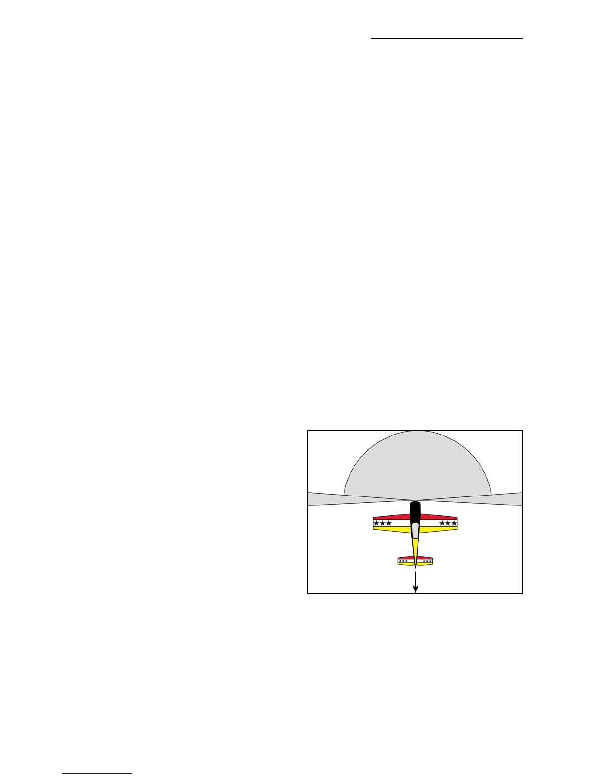
Make sure that the plane is secured properly when you start the engine. Have at least 2 helpers
hold your plane from the tail end, or from behind the wing tips, before you start the engine. Make
sure that all spectators are behind, or far in front, of the aircraft when running up the engine.
Make sure that you range check your R/C system thoroughly before the first flight. It is absolutely necessary to range check your complete R/C installation first WITHOUT the engine running.
Leave the transmitter antenna retracted, and check the distance you can walk before ‘fail-safe’
occurs. Then start up the engine, run it at about half throttle and repeat this range check with the
engine running. Make sure that there is no range reduction before ‘fail-safe’ occurs. Only then
Composite-ARF Extra 300SX (2.6m span)
3
NO !!!
Secure the plane
before starting the engine.
DANGER ZONES
NO
NO
Page 4

Composite-ARF Extra 300SX (2.6m span)
4
make the 1st flight. If you feel that the range with engine running is less then with the engine off,
please contact the radio supplier and the engine manufacturer and DON’T FLY at that time.
Check for vibrations through the whole throttle range. The engine should run smoothly with no
unusual vibration. If you think that there are any excessive vibrations at any engine rpm’s, DON’T
FLY at this time and check your engine, spinner and propeller for proper balancing. The lightweight sandwich composite parts don’t like too much vibration and they can suffer damage. The
low mass of all the parts results in a low physical inertia, so that any excess vibrations can affect
the servos and linkages.
Make sure that your main and stab tubes are not damaged. Check that the front and rear antirotation pins for the wings and horizontal stabiliser are located correctly in their holes, and are
not loose. Check that the 4 plastic wing retaining nuts are tight, that the M3 bolts retaining the
horizontal stablisers on to the aluminium tube are installed and tight, and that the hinge wires for
the rudder and elevators cannot come out.
If you carefully checked all the points above and followed our advice exactly, you will have a safe
and successful first flight - and many hours of pleasure with your Composite-ARF Extra 330SX.
General information about
fully-composite aircraft structure and design
All the parts are produced in negative molds, manufactured using vacuum-bagged sandwich
construction technology. All parts are painted in the moulds, either single colour or designer
colour schemes. A new production method, called TAVS (Total Area Vacuum Sandwich), enables
us to present this aircraft with incredible built-in strength, while still being lightweight, and for a
price that nobody could even consider some years ago. This production process has huge
advantages, but a few disadvantages as well. These facts need to be explained in advance for
your better understanding.
Description of Parts
The Wings:
Both wing halves are made in negative moulds, fully vacuum-bagged, using only 2 layers of cloth
in combination with a hard 2mm foam sandwich to form a hard and durable outer skin. Because
of this TAVS technology no additional structural parts are needed except for the main spar tube.
The ailerons are already hinged for you. They are laminated in the wing mould and are attached
to the main wing with a special nylon hinge-cloth, sandwiched between the outer skin and the
foam. This nylon hinge is 100% safe and durable. You never have to worry about breaking it, or
wearing it out. There is no gap at all on the top wing surface, and there is a very narrow slot in
the bottom surface, where the aileron slides under the main wing skin during down throw. This
hinge setup is the cleanest you can ever obtain, but you have to take some care during assembly for proper installation and servo set up.
First, the hinge line is on the top surface of the wing, not in the centre. This is NOT a disadvantage, if you set in about 10% NEGATIVE aileron differential in your transmitter program. This
means that the ‘down’ throw needs to be about 10% more than the up throw.
Page 5
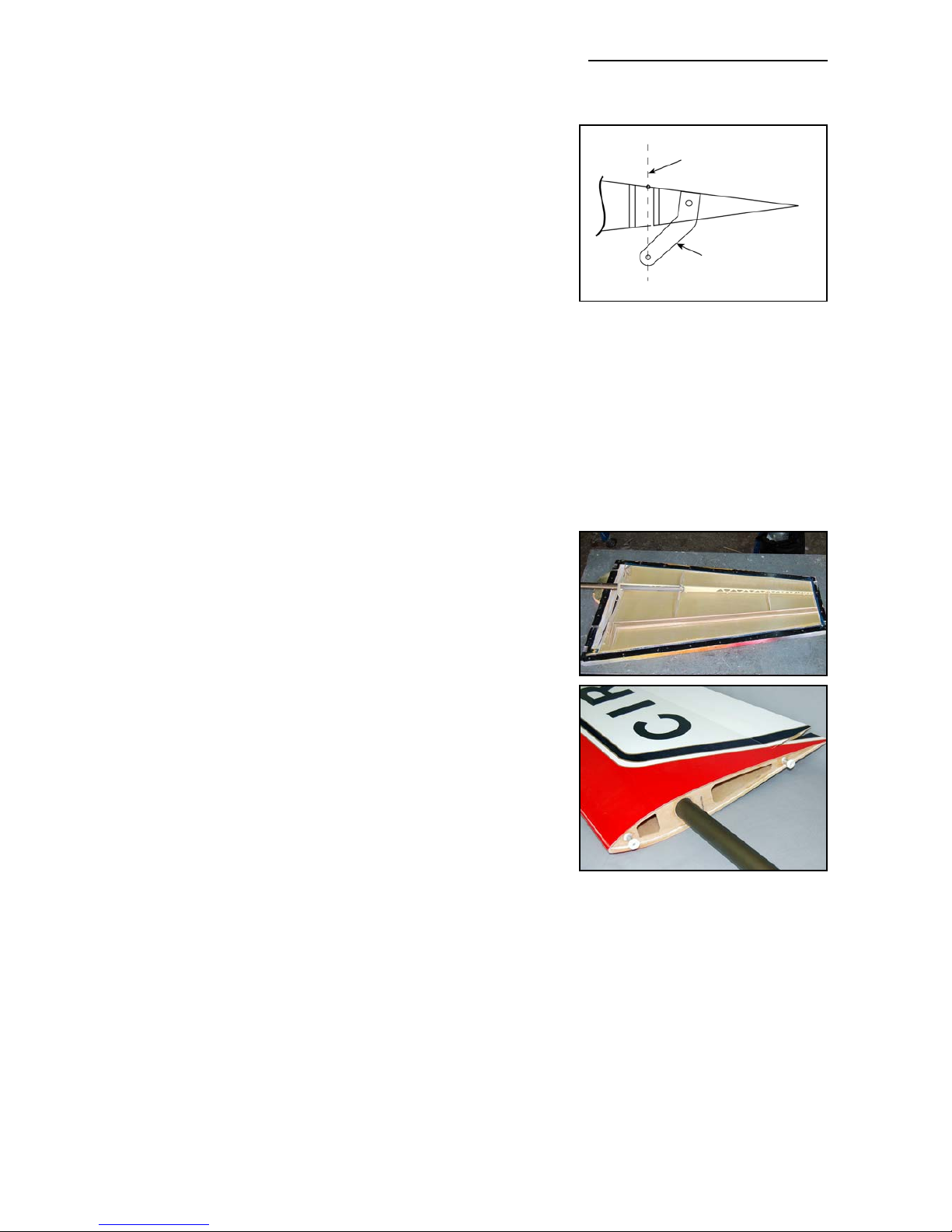
Why? Because the axis of the hinge is not at the centreline
of the aileron, so it moves slightly in and out when it travels, and the aileron gets a little "bigger" in surface area
when moving up, and "smaller" when moving down. This is
why you have to set the negative differential in your transmitter to compensate for the size changing. 10% is a good
starting point, and you will find out the exact setting during
the first flights, doing fast vertical rolls and watching the
fuselage rolling in a perfect line. You can set it perfectly, this
is guaranteed.
The bottom slot needs some explanation, too. The cut line is exactly in the correct position so
that the aileron slides under the wing skin smoothly. If the cut was a few mm forward or back, it
would not work properly. So, make sure that the lip is not damaged, and that the aileron slides
under this lip perfectly. It will NOT lock at any time, as long as the lip is not damaged. If damage
occurs to the lip, you can cut off 2-3 mm, but you should NEVER need to cut off more than this.
Make sure that the control horns are glued into the ailerons properly. The hole in the phenolic
horn for the quick-link needs to be exactly perpendicular to the hinge axis line, and in this
manual we show you a simple way to ensure that the horns in all pairs of control surfaces will be
identical, making it easy to set up your R/C for accurate flying manoeuvres.
The wings are already set-up with servo covers and hatches for 2 servos per aileron, and we recommend a pair of
high-torque servos, like the JR D8411, in each wing. Our
servo covers and milled plywood mounts make both installation, and exchange if necessary, very quick and easy and
provide a rock solid servo mounting and linkage system.
The wings are attached to the fuselage with the 4 threaded
aluminium dowel anti-rotation pins, with 4 plastic nuts
inside the fuselage. If the aluminium dowels come loose in
the wing, the wing will slide outwards, away from the fuselage, and the main spar tube will definitely break. So take
great care to inspect the glue joints of these anti-rotation
dowels in the wing REGULARLY. Excessive vibrations or
hard shocks can cause the glue joints to weaken or break.
Monitor these joints whenever you set up your plane. Never
forget to tighten the nuts inside the fuselage. Please DO
NOT modify these attachment dowels in any way, their perfect function is proven for many years.
The Fuselage:
The fuselage is also made in negative moulds, and is all constructed using TAVS technology. All
the loadbearing internal parts are installed during manufacture, to ensure accurate location and
reduce your assembly time. The fibreglass tubes in the wings to receive the wing spar tube, the
stab spar tubes, and the holes and reinforcement plates for the anti-rotation dowels, are already
installed. There is no need to even check the incidences - you can be assured that these are
already set in the moulds so that no adjustment is necessary.
The landing gear mount is strong and doesn’t need any extra reinforcement. The fuselage is
extremely light weight, and the gear loads need to be led into the structure gently. No glue joint
needs to be stronger than the materials that it is attached to, as it would just result in increased
weight for no advantage. The landing gear is a fairly flexible design, which works very much like
Composite-ARF Extra 300SX (2.6m span)
5
Centreline of hinge axis
Phenolic control horn
Page 6
shock absorbers. This plane is not made for crashing, but
the landing gear will take some hard landings without problems. Do not change or modify it, as the results would only
be negative. We had plenty of time and experience to engineer the strength needed in this area - and we did !
The motordome and firewall are a fully integral parts of the
fuselage, and provide plenty of strength for any engines up
to 120cc on the market today. See the Engine Installation
section for details of engine and setting thrust angles.
The engine cowling should be attached using the method
shown. It is only a little work and this mounting has been
tested and proven for many years.
The Stabilisers:
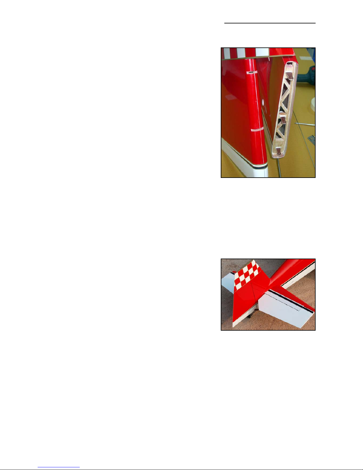
The stab parts are also vacuum bagged sandwiched. The
rudder is hinged with a 2mmØ steel wire, and the elevator
control surfaces are hinged with 4mmØ tubes, fitted
through phenolic hinge bearing plates which are jig-installed
during manufacture for perfect alignment.
The rudder and elevator design allows for at least 50
degrees throw. For the Extra it is mandatory that the tail area
is extraordinarily light weight, so the stab is designed for one
powerful servo installed in each half. All the structural parts
are preinstalled. The horizontal stabs are mounted with one
20mm aluminum tube and one aluminium anti-rotation pin
each.
Servo Screws:
Fix the all the servos into the milled plywood servo mounts
using the 2.9 Ø x13mm sheet metal screws provided in the
kit, not the standard screws normally supplied with servos
by the servo manufacturer. This is because all the holes in
our milled servo mounts are 2mm diameter, due to our CNC
manufacturing process, and this is too big for the normal
screws.
Take Care:
Composite sandwich parts are extremely strong, but fragile at the same time. Always keep in
mind that these contest airplanes are designed for minimum weight and maximum strength in
flight. Please take care of it, especially when it is being transported, to make sure that none of
the critical parts and linkages are damaged. Always handle your airplane with great care, especially on the ground and during transport, so you will have many hours of pleasure with it.
Composite-ARF Extra 300SX (2.6m span)
6
(above) The lightweight fin-post
has the phenolic rudder hinge
posts already installed and aligned
at the factory. The corresponding
tubes are also installed in the rudder for the hinge wire.
(below) The elevator hinging uses
4mm diameter aluminum tubes,
inside phenolic hinge posts that
are factory-installed and aligned.
Page 7

Accessories
Below are the things you may need to get your Composite-ARF Extra 300SX in the air. Some of
them are mandatory, some of them can be chosen by you. What we list here are highly recommended parts, and have been thoroughly tested.
1. Power servos (min. 8 required). We highly recommend JR 8411 or 8511/8611 for all con
trol surfaces. For Futaba users, we recommend 2 x S9351’s for each Aileron, 1 x S9351
for each elevator, and either 2 x S3951’s or 2 x S9152’s for rudder.
2. Aluminium servo output discs, or full metal arms (8 pieces). We strongly recommend that
you attach the phenolic servo extension arms provided in the kit to metal servo output
discs, or use full metal servo arms (eg: SWB ‘Double-Loc’ type)
3. Throttle servo. Any standard servo will do (eg: JR/Graupner 4041/5391)
4. Aluminum Spinner 120 - 125 mm/4.75 - 5” dia. eg: Tru-Turn. (Ø120mm carbon spinner
& CNC T6 alu. backplate available from C-ARF as an option, #810100 - 810103)
5. Main wheels 115 - 125 mm (4.5 - 5"). Kavan Light or Dubro wheels are recommended.
6. Engine 75 - 100cc. The DA-100 is probably the most commonly used engine for our 2.6m
span Extras. In these instructions we show the installation of this, and also a lightweight
option with a 3W 80cc single cylinder and tuned pipe set-up.
7. Muffler/Canister or Tuned pipe(s) and headers. (Headers, canisters, tuned pipes and
Teflon joiners are available from C-ARF as options. See our webpage for availability)
8. Tailwheel assembly. (Available as an option from C-ARF. Product # 801000.)
9. High quality heavy-duty servo extension cables, with gold connectors. High quality
receiver and ignition switches, etc.
10. Receiver batteries.
11. Powerbox and dual powerswitches for dual batteries (available from C-ARF as an option)
12. Fuel tank (750 - 900 ml) with gasoline stopper. We use Dubro.
13. Cable ties in various lengths.
14. Propeller. Carbon Meijzlik or Menz 28 x10 for DA-100. 26 x 12 or 27 x 10 for 3-W 80cc.
Composite-ARF Extra 300SX (2.6m span)
7
Page 8

Tools
This is a very quick and easy plane to build, not requiring difficult techniques or special equipment, but even the building of Composite-ARF aircraft requires some suitable tools! You will
probably have all these tools in your workshop anyway, but if not, they should be available in all
good hobby shops, or hardware stores like "Home Depot" or similar.
1. Sharp knife (X-Acto or similar)
2. Allen key set (metric) 2.5mm, 3mm, 4mm & 5mm.
3. Sharp scissors
4. Pliers (various types)
5. Wrenches (metric)
6. Slotted and Phillips screwdrivers (various sizes)
7. M3 tapping tool (metric)
8. Drills of various sizes
9. Small spirit level, or incidence meter.
10. Dremel tool (or Proxxon, or similar) with cutting discs, sanding tools and mills.
11. Sandpaper (various grits), or Permagrit sanding tools (high quality).
12. Carpet, bubble wrap or soft cloth to cover your work bench (most important !)
13. Car wax polish (clear)
14. Paper masking tape
15. Denaturised alcohol, or similar (for cleaning joints before gluing)
Adhesives and Solvents
Not all types of glues are suited to working with composite parts. Here is a selection of what we
normally use, and what we can truly recommend. Please don’t use inferior quality glues - you will
end up with an inferior quality plane, that is not so strong or safe.
High performance models require good gluing techniques. We highly recommend that you use
either a slow (minimum 30 minute cure) epoxy resin and milled fibre mixture, or a slow filled
thixotropic epoxy for gluing highly stressed joints (eg: Hysol 9462). The self-mixing nozzles make
it easy to apply exactly the required amount, in exactly the right place, and it will not run or flow
onto places where you don’t want it! It takes about 1 - 2 hours to start to harden so it also gives
plenty of time for accurate assembly. Finally it gives a superb bond on all fibreglass and wood
surfaces. Of course there are many similar glues available, and you can use your favourite type.
1. CA glue ‘Thin’ and ‘Thick’ types. We recommend ZAP, as this is very high quality.
2. ZAP-O or Plasti-ZAP, odourless, or ZAP canopy glue 560 (for clear canopy)
3. 30 minute epoxy (stressed joints must be glued with at least 30 min & NOT 5 min epoxy).
4. Loctite Hysol 9462 or equivalent (optional, but highly recommended)
5. Epoxy laminating resin (12 - 24 hr cure) with hardener.
6. Milled glass fibre, for adding to slow epoxy for stronger joints.
7. Micro-balloons, for adding to slow epoxy for lightweight filling.
8. Thread-locking compound (Loctite 243, ZAP Z-42, or equivalent)
Composite-ARF Extra 300SX (2.6m span)
8
Page 9
We take great care during production at the factory to ensure that all joints are properly glued,
but of course it is wise to check these yourself and re-glue any that might just have been missed.
When sanding areas on the inside of the composite sandwich parts to prepare the surface for gluing something onto
it, do NOT sand through the layer of lightweight glasscloth
on the inside foam sandwich. It is only necessary to rough
up the surface, with 80/120 grit, and wipe off any dust with
acetone or de-natured alcohol (or similar) before gluing to
make a perfect joint. Of course, you should always prepare
both parts to be joined before gluing for the highest quality
joints. Don’t use Acetone for cleaning external, painted,
surfaces as you will damage the paint.
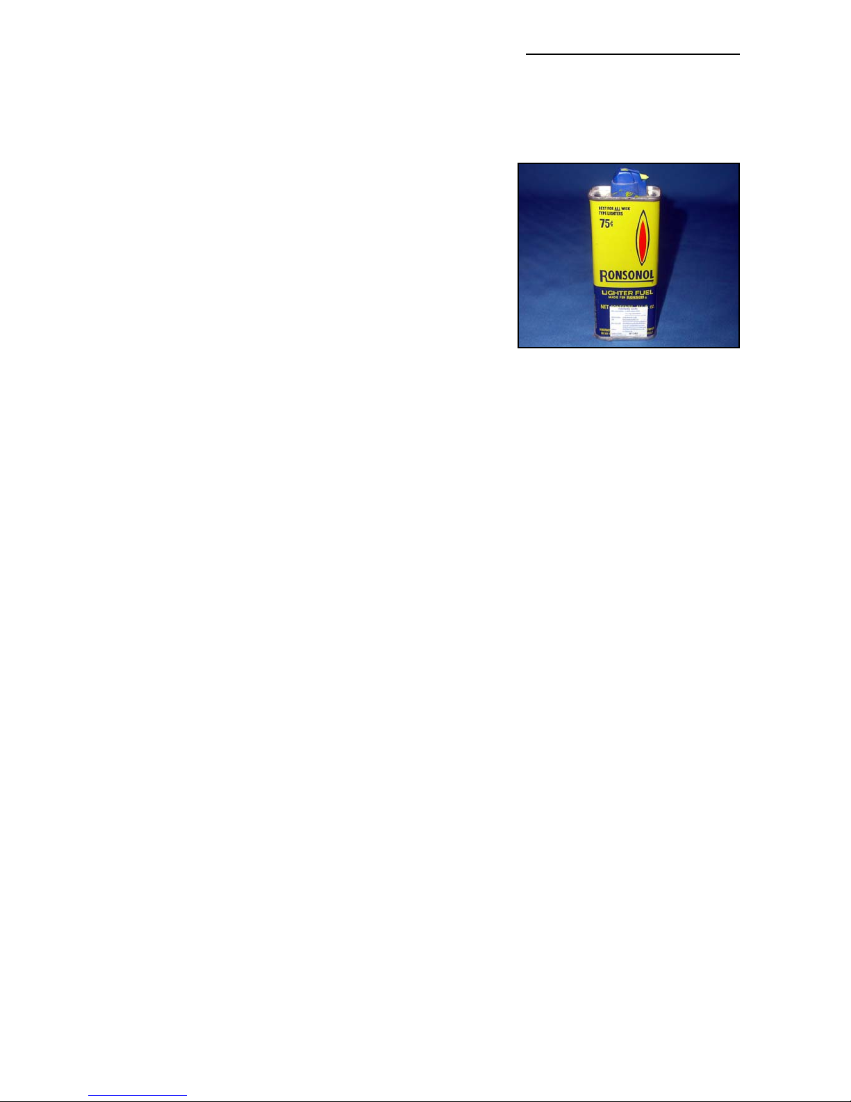
Tip: For cleaning small (uncured) glue spots or marks off
the painted surfaces you can use old-fashioned liquid cigarette-lighter fuel, like ‘Ronsonol’ or equivalent. This does not
damage the paint, as Acetone and many other solvents will,
and this is what we use at the factory.
At Composite-ARF we try our best to offer you a high quality kit, with outstanding value-formoney, and as complete as possible. However, if you feel that some additional or different hardware should be included, please feel free to let us know.
Email us: [email protected].
We know that even good things can be made better !
Did you read the hints and warnings above and the instructions carefully?
Did you understand everything in this manual completely?
Then, and only then, let’s start assembling your Composite-ARF Extra 300SX
Composite-ARF Extra 300SX (2.6m span)
9
TIP: Lighter fluid is excellent for
cleaning small marks, uncured
glue, or similar off the painted surface of the plane - without damaging the colour finish.
Page 10
Building Instructions
General Tips:
We recommend that you follow the order of construction shown in this manual for the fuselage,
as it makes access to everything easier and saves time in the end. The wings and stabs can be
done at almost any point, and only need servos and control horns installing anyway.
The first thing to do is protect the finished paint on the outside of the model from scratches and
dents during building - so cover your work table with a piece of soft carpet, cloth or bubble-plastic. The best way to stop small spots of glue getting stuck to the outside of the fuselage is to give
the whole model 2 good coats of clear car wax first, but of course you must be sure to remove
this 100% completely before adding any decals or markings. Additionally you can cover the
majority of the fuselage with the bubble-plastic used to pack your model for shipping, fixed with
paper masking tape, which also protects it very well.
When sanding any areas of the inside of the fuselage to prepare the surface for gluing something onto it, do NOT sand right through the layer of glasscloth on the inside foam sandwich !
It is only necessary to rough up the surface, with 60/80 grit or equivalent, and wipe off any dust
with alcohol (or similar) before gluing to make a perfect joint.
Before starting construction it is a good idea to check inside the fuselage for any loose glass
fibres that could cut your hands, and a quick scuff over any of these with a coarse Scotchbrite
pad will remove them.
Note: It is very important to prepare the inside of the fuselage properly, by roughing up and
cleaning the surface, before gluing any parts to it.
Landing Gear
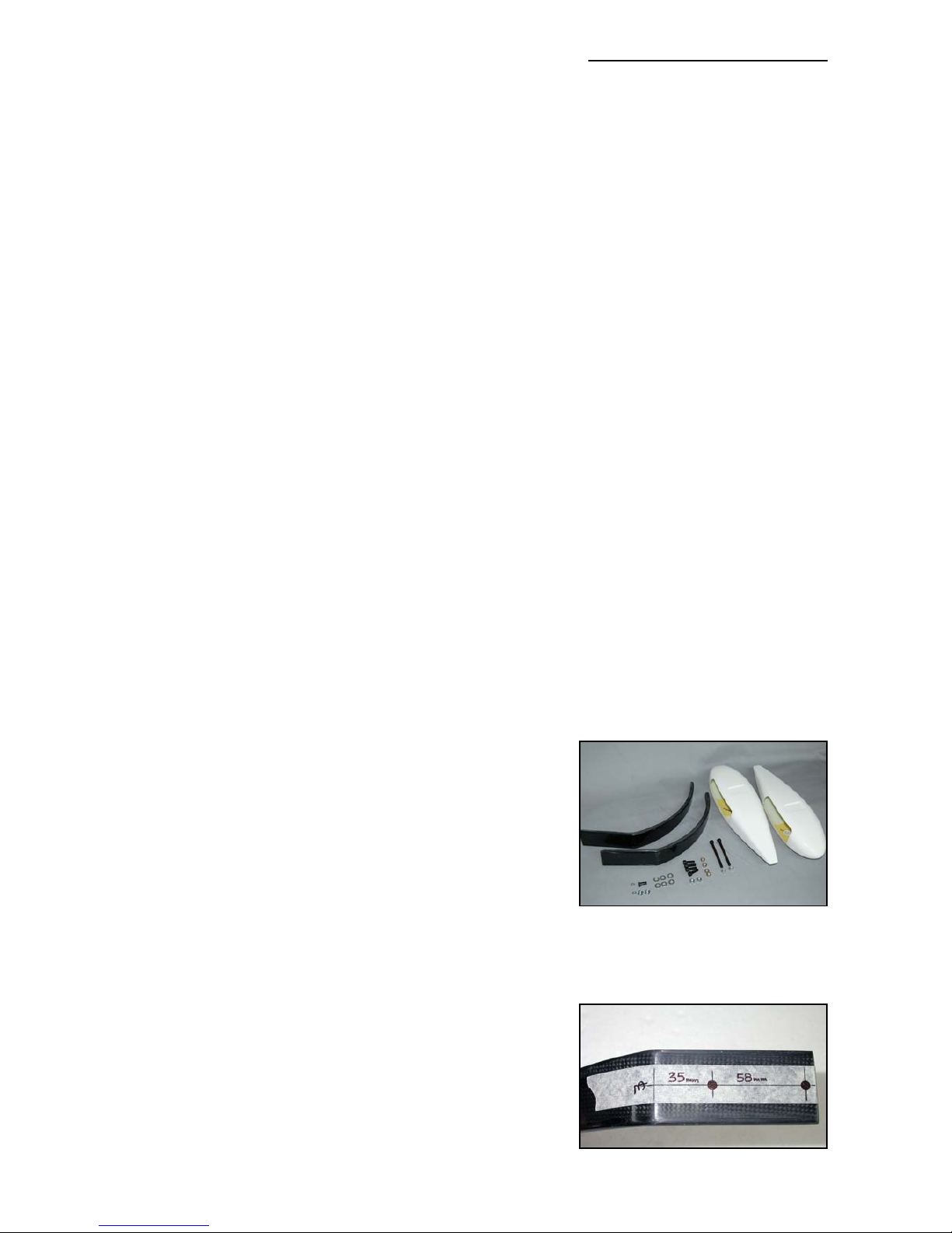
The 1st job is to fit the landing gear legs (wheel pants and
cuffs can be done later) - and you can leave these in place
to protect the bottom of the fuselage during assembly.
The Composite-ARF landing gear for the Extras consists of
45 deg laminated carbon fibre cloth and a huge number of
carbon rovings inside, all made under vacuum and heatcured. However it is still light weight, and retains enough
flexibility to take the shock out of any landings that are lessthan-perfect!
Mark the centreline on each carbon landing gear leg, and
drill 2 holes with a sharp 6.5mm Ø drill as shown in the
photo. The centres of the holes are measured from the
bend in the leg that will be flush with the outside of the fuselage. The outer hole is 35mm from the bend, and the inner
hole is 58mm (2 5/16”) from the 1st hole. Both main legs
are identical, and can be used either side.
The carbon landing gear legs are secured to the revised
aircraft-grade plywood supports and bulkheads in the fuse-
Composite-ARF Extra 300SX (2.6m span)
10
(above) The main parts used to
assemble the Landing Gear.
(below) Drill 2 x 6.5mm Ø holes for
bolting in the Landing Gear.
Page 11
Composite-ARF Extra 300SX (2.6m span)
lage (factory-installed), using the supplied M6 x 20mm bolts
and washers into the pre-installed T-nuts. See photo P1.
Note that the bend on the underside of each landing gear
leg should be flush with the outside surface of the fuselage
skin, and therefore you may need to chamfer the bottom
edges of the factory-cut slots in the fuselage a little with a
file to make sure that there is no interference.
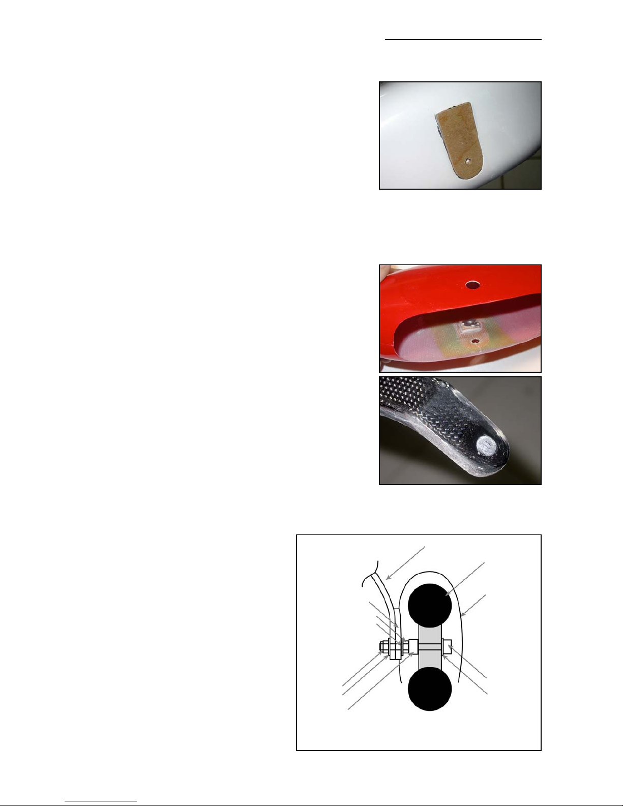
Sand the inside of the ‘U-shape’ molded in recesses in the
wheelpants, and glue in the milled 3mm plywood U-shaped
part as shown, using 30 min. epoxy. At the same time glue
in a milled 20 x 20mm square plywood plate on the inside
of the wheelpant, against the kevlar reinforcement, with the
centre of the square about 6mm (1/4”) behind the vertical
centre from the axle position, and about 25mm (1”) above
it. This part is reinforcement for the M3 T-nut that will be
installed later. (see photo P2)
Drill a 6mm Ø hole in the bottom of each carbon leg for the
axle, through the small dimple that is molded-in to mark the
correct position. Drill 6mm through the hole in the U-shaped
ply part on each wheel pant. Drill an 9mm diameter hole in
the outside of the both wheelpants, directly opposite the
6mm hole for the axle. This hole is for inserting the M6 x
70mm hardened bolt that is used as the axle.
Insert the bolt into the wheelpant through the 9mm hole,
threading on the washers and wheel collars, used as spacers, as needed to centre the wheel in the pant. The last 2
items to go onto the axle are a plain M6 nut and a washer,
which will be against the inner surface of the wheel pant.
(see typical example below). Secure the axle onto the landing gear with a washer and M6 lock-nut on the inside of the
carbon leg. During final assembly a drop of Loctite on the
M6 lock-nut is good insurance.
Set the fuselage on a level surface with
the tailwheel in place, and adjust the
angle of the wheelpants so that they are
parallel with each other, and will not
touch the ground on takeoff or landing.
Tighten the M6 stop-nut firmly, and tack
glue the carbon leg to the plywood ‘Ushape’ with 1 small drop of CA to make
sure it cannot move during the next step.
Drill 3mm hole through the middle of the
carbon leg, 25mm above the centre of
the axle, into the small ply square inside
the wheel pant, and fit an M3 x 16mm
bolt and washer in place.
Remove the axle, wheel and spacers and
11
(above & below) Glue the milled
plywood reinforcements to the
inside & outside of the wheelpant
as shown. The inside plate will
have an M3 T-nut glued to it later.
(above) The moulded dimple in
the bottom of the carbon legs. Drill
a central hole of 6mm diameter.
Carbonfibre landing
gear leg
120-125mm
Ø wheel
wheelpant
M6 bolthead
washer
6mm wheel
collar
washer
washer
M6 locknut
M6 nut
milled plywood
WHEELPANT X-Section
Page 12
carbon leg. Redrill the hole in the wheelpant and plywood square only (not the carbon leg) to
4.5mm diameter, and glue an M3 T-nut to the plywood square inside the wheelpant for the M3
bolt. This bolt maintains the correct angle of the wheel pants to the ground. (see photo P3)
Do not use a bolt larger than M3, as the larger diameter hole in the leg can weaken it.
The typical order of fitting the wheelcollars, washers and wheel onto the axle, to centre the wheel
in the wheelpant, is shown in the diagram above - but of course it will vary slightly depending on
the size and type of wheel used.
You can use any 4.5” - 5" main wheels. Kavan wheels are
very lightweight, but not very durable on asphalt runways,
and Dubro wheels are a little heavier but much more solid.
Leg Cuffs
The Extra 300SX has fairings at the top of each LG leg
where they enter the fuselage, and these are supplied in
the kit as lightweight fibreglass mouldings. It is a little more
difficult to remove the LG legs for replacement when the
cuffs are in place, and we suggest that they are glued in
place onto the fuselage with clear silicone adhesive (bath
sealant), so they can easily be removed if necessary. Note
that there is a ‘right’ and a ‘left’ leg cuff, but which is which
will be very obvious when you trial fit them to the fuselage!
Mill the slot in each cuff for the carbon legs, leaving about
0.5mm (1/15”) gap all around to allow for the flexing of the
carbon leg during landing, and to make it easier to remove
the carbon legs from the fuselage. Sand border of the cuffs
smooth, and glue to fuselage with a little clear silicone
adhesive.
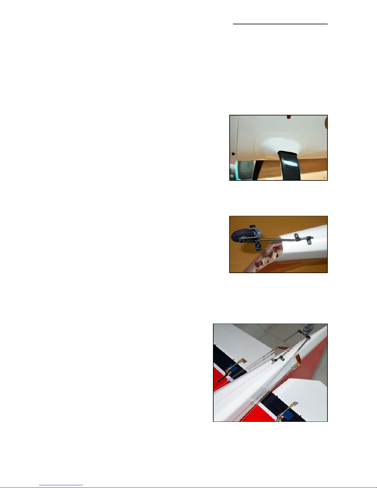
Tailwheel
The tail wheel setup shown in these photos is an optional
part available from C-ARF (# 801000), and is mounted with
4 sheet metal screws and 2 plastic ‘U’ brackets under the
fuselage, screwed into the plywood reinforcement
that’s installed in the fuselage at the factory.
You don’t need to make the tailwheel steerable if flying from grass surfaces, a simple castoring action is
fine. However, for hard runways you may prefer to
connect it either to the rudder horn with 2 springs as
shown, or even better to the rudder pull-pull cables
about 250mm in front of the rudder leading edge - as
shown here. It’s easy to make the springs by winding
some 0.8mm Ø piano wire around a 5mm drill bit,
turned slowly in a battery-drill, with a small hook in
each end to connect to the tailwheel steering arms.
(see also photo P21)
Remember - keep it lightweight at the tail end!
Composite-ARF Extra 300SX (2.6m span)
12
(above) Optional tailwheel assembly from Composite-ARF.
(below) Tailwheel assembly can be
connected to rudder horn OR rudder cables with springs for
improved steering.
(above) Fibreglass leg Cuffs are
secured to fuselage with a little
clear silicone adhesive, allowing
easy removal if necessary.
Page 13
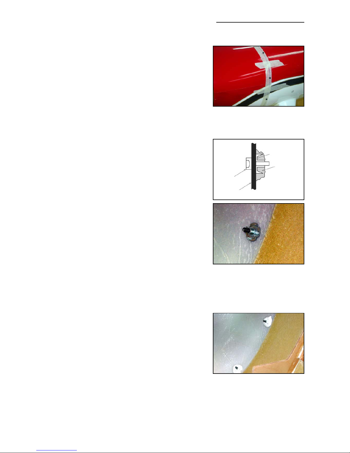
Cowling
The 1 piece cowling is already cut and trimmed at the factory, and should need almost no adjustment for a perfect fit.
With the main undercarriage legs bolted into place, install
the wing tube in the fuselage sleeve and place a small spirit or incidence meter level on top of it to set the plane exactly level (side to side). Pack under one undercarriage leg as
necessary to get it level on your building table.
If necessary, sand the fibreglass joining tapes inside the
back edge of the cowl slightly to get a perfectly flush fit
between the cowling and the fuselage sides. Trial fit the
cowling, and use the spirit level or an incidence meter on
the lower (flat) part of the cutout at the front of the cowl to
make sure that it is level and properly centred. Tape the
cowl firmly into position, and mark a centreline on the top of
the cowl and the fuselage, on masking tape.
The cowling is held in place with 9 bolts (M3 x 12mm),
washers and blind nuts. Drill one 3mm diameter hole at the
top/centreline of the cowl, approx. 8mm (5/16”) in front of
the back edge of the cowling, and insert an M3 x 12mm
bolt. Thread a T-nut onto the bolt inside the fuselage, and
secure it to the fuselage with one small drop of thick CA.
Note that the blind nuts are fitted reversed, with the spikes
pointing inwards! Check alignment again, and then drill and
fit the other 8 bolts in the same way, securing the blind nuts
to the inside of the fuselage with a single drop of thick CA.
Space the 9 bolts 105mm (4.2”) apart, so that the lowest 2
bolts will be quite close to the edges of the square cutout in
the bottom of the cowling, which retains it properly.
Don’t forget to wax, or oil, the M3 bolts first, to make sure
that you don’t accidentally glue any of the bolts to the cowling or into the blind nuts! Finally remove all the bolts and
cowling, and glue the 9 blind nuts in place properly using a
medium-thick mixture of 30 minute epoxy and micro-balloons, as shown. During final assembly, add the supplied
M3 washers under the heads of all the M3 bolts.
Composite-ARF Extra 300SX (2.6m span)
13
(above) Cowling is secured with
nine M3 bolts, into T-nuts fitted in
reverse, glued inside fuselage with
a thick micro-balloons mixture.
(above & below) Tack glue the Tnuts in position with a small drop
of thick CA first. When cowling is
correct, secure all the T-nuts with
a drop of, fairly wet, epoxy and
microballoons mixture as shown.
M3 T-nut
M3 bolt
cowl/fuselage
Epoxy
& micro
mixture.
Page 14
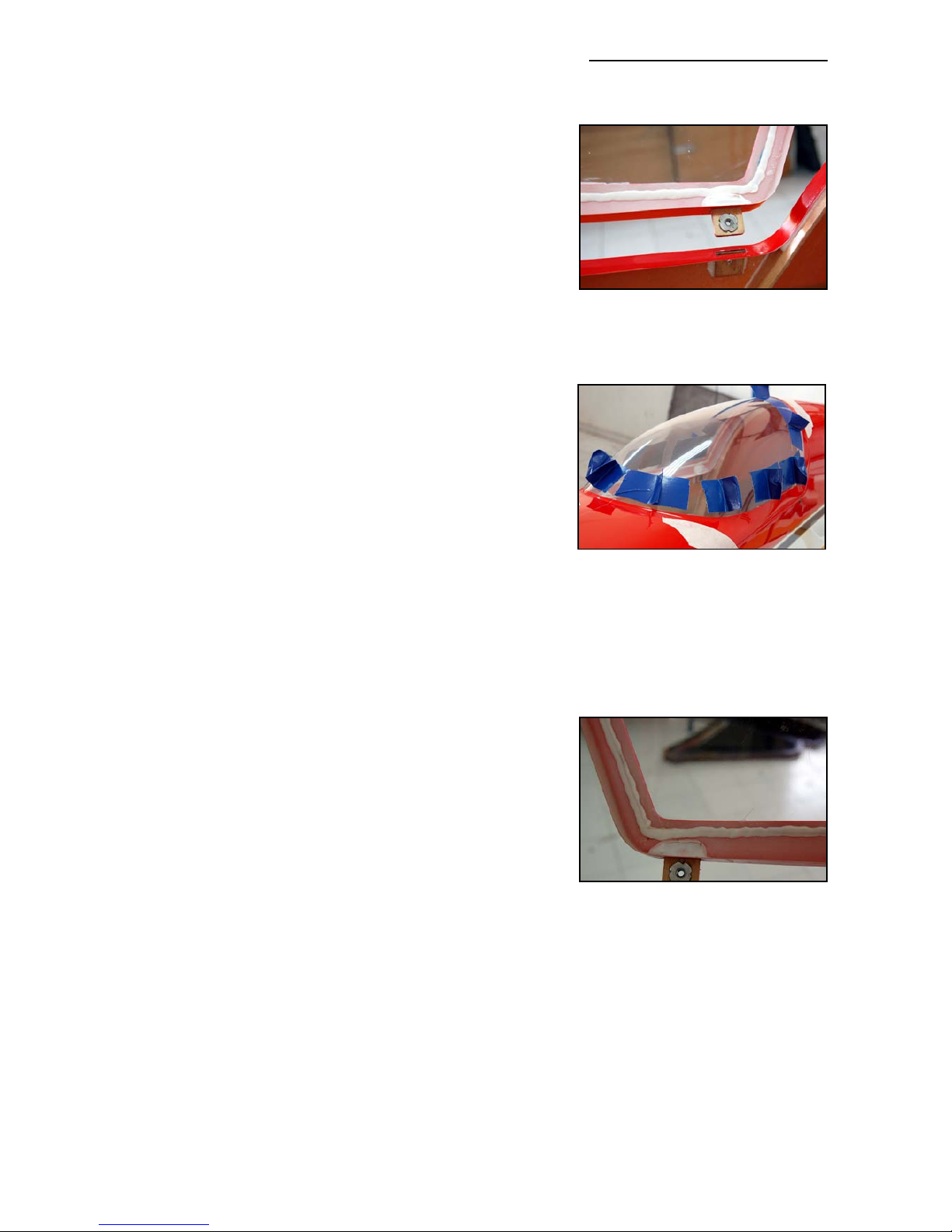
Canopy Frame
The fibreglass canopy frame mountings are already completed for you at the factory. It is secured to the fuselage
with four M4 x 12mm allen bolts, fitted from the outside of
the fuselage, through the plywood tabs that are glued to the
canopy frame, into M4 T-nuts. This system has been very
well proven on all of our aerobatic planes, and is a strong
rattle-free solution.
Fitting the clear canopy into the frame can be a little bit
tricky, but this is a step by step guide of how we do it:
Sand the inside edges of the canopy frame carefully with
120 grit sandpaper, especially the fibreglass joining tapes,
to ensure a perfect fit of the canopy. Fit the canopy frame
on the fuselage and secure with all 4 bolts. Lay the canopy
on top of the frame, view from the front to check that it is
centred and symettrically positioned, and then mark the
approx. shape with a felt pen or wax crayon. Cut the outer
border of the clear canopy with sharp scissors, about
12mm (1/2”) too big all around. Unless you are in a very
warm room, we recommend that the canopy is slightly
warmed up with a hair dryer to prevent cracking - but be
careful not to melt or deform it! When the canopy fits inside
the frame, tape it into position temporarily, and accurately
mark the edge of the frame on the canopy with a wax crayon. Remove the canopy and trim exactly to shape, leaving
about 6mm overlap outside the line all around.
Refit the canopy into the frame, and tape into position from
the inside. Push the canopy up tightly inside the back of the
frame and fix the bottom 2 back corners with one small drop
of odorless CA each (ZAP-O recommended).
Note: Do NOT use any CA accelerator/kicker - you will
immediately ‘fog’ the clear canopy!
Make visual check from the front and back to make sure
sure that the canopy is straight. Make several hand-holds
with strong tape (see photo) to make holding and positioning the canopy easy. Remount the
canopy frame to the fuselage (use all 4 bolts), and tape the canopy frame tightly to the fuselage
all around. Using the tape handles to pull the canopy outwards firmly against the frame, working
from the back towards the front, glue the edges of the canopy in place in 2 more places each
side, with just a single small drop of CA at each position, all the time checking that the edge of
the canopy is tight up against the frame at the front.
Now that the canopy is fixed in position and cannot twist or warp anymore, you can carefully
remove the canopy frame from the fuselage, and use a 30 minute or 24hr epoxy and micro-balloon mixture for gluing all the edges to the frame on the inside surface (see photo above). It is
most important that the canopy cannot come off in flight, so make sure that the bead of glue traps
the clear canopy firmly in place. Re-secure the canopy frame onto the fuselage with all 4 bolts
Composite-ARF Extra 300SX (2.6m span)
14
(above) Use duct-tape handles to
pull the clear canopy tightly against
the canopy frame while gluing it in
position with a few very small
drops of odorless-CA.
(below) When fixed, remove frame
& secure edges of canopy firmly
with epoxy/micro-balloon mixture
(above) The canopy frame is
secured to the fuselage with 4
tabs, M4 bolts and T-nuts, all finished at the factory for you.
Page 15
Composite-ARF Extra 300SX (2.6m span)
while the epoxy-microballoons mixture is curing to prevent any warps or twists.
If you wish you can tint the inside of the canopy using one of the aerosol spray paints used for
painting the inside of polycarbonate car bodies (eg: the Tamiya or Lexanit ranges). Use many
very light ‘mist’ coats to get even coverage.
Horizontal Stabs
The stabilisers are 95% finished at the factory, and only need the servos, horns and linkages
installing. Insert the 20mm aluminium tube spar in the fuselage sleeve, and slide on both stabs
to check the fit between the root ribs and the fuselage. You can sand the root of the stabs slightly to make a perfect joint if needed, and if the spar tube is a fraction long you must shorten it.
The elevators are hinged to each stab using the 4mm Ø aluminium tubes provided. Make sure
there is no burr on either end of the tubes, and chamfer the ends slightly with fine sandpaper to
make it easier to get them through the holes in the phenolic hinge plates. Be careful inserting
them, and if they are a bit stiff, then use a little grease on the tubes. Don’t use too much force,
otherwise a phenolic hinge post inside might break loose. Leave the tubes a bit too long during
assembly, and cut them to exact length when the model is finished. During final assembly, retain
both ends of the tubes with small pieces of clear tape on the root and tip ends of the elevators.
Servos
You have a choice of elevator servos; either a hi-power digital JR8511/8611 in each stab, or an
JR8411, which is also sufficient. Although the JR8511/8611 servos are about 1 mm longer and
wider than the 8411, both sizes will fit in the milled servo
cutouts in the ribs. If using Futaba servos, we recommend
that you use S9351’s, which also fit the milled servo cutouts
in the ribs. Please do not use inferior quality servos, or
servo arms, in this plane. It will result in an aircraft that does
not fly accurately, reliably or safely.
The servos are installed with the output shafts towards the
stab trailing edge, and they must be installed using the
2.9mm Ø x 13mm sheetmetal screws provided in the kit,
not the standard screws provided with the servos which are
too small for the Ø 2mm milled holes.
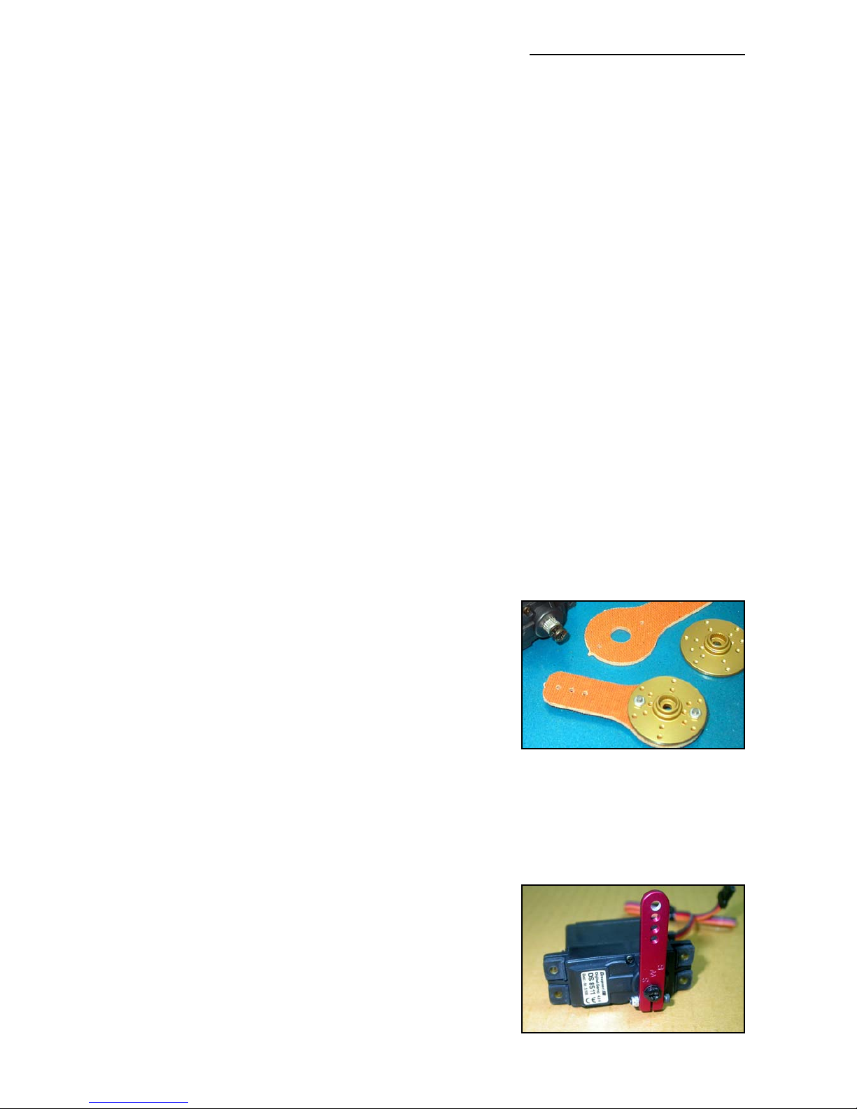
Servo arms
To obtain sufficient elevator throws, quite long servo output
arms are needed (30 - 35mm/1.25 -1.5”). In the kit we supply phenolic servo arm extensions for this purpose, which
can be fitted onto your servo output discs to achieve the
throws. However, it is mandatory to secure these to metal
servo output discs, or to use full metal servo arms (like
those shown below from SWB) - and not the standard plastic output discs supplied with the servos. The extreme
torque of the current hi-torque digital servos can strip the
plastic splines from the inside of the disc - which will result
in immediate flutter and destruction of your Extra. Several
15
(above) If you use the phenolic
servo arm extensions, you MUST
bolt these to metal servo discs.
(below) The alternative is full metal
servo arms, such as these SWB
‘Double-Loc’ types that we use on
most of our factory planes.
Page 16
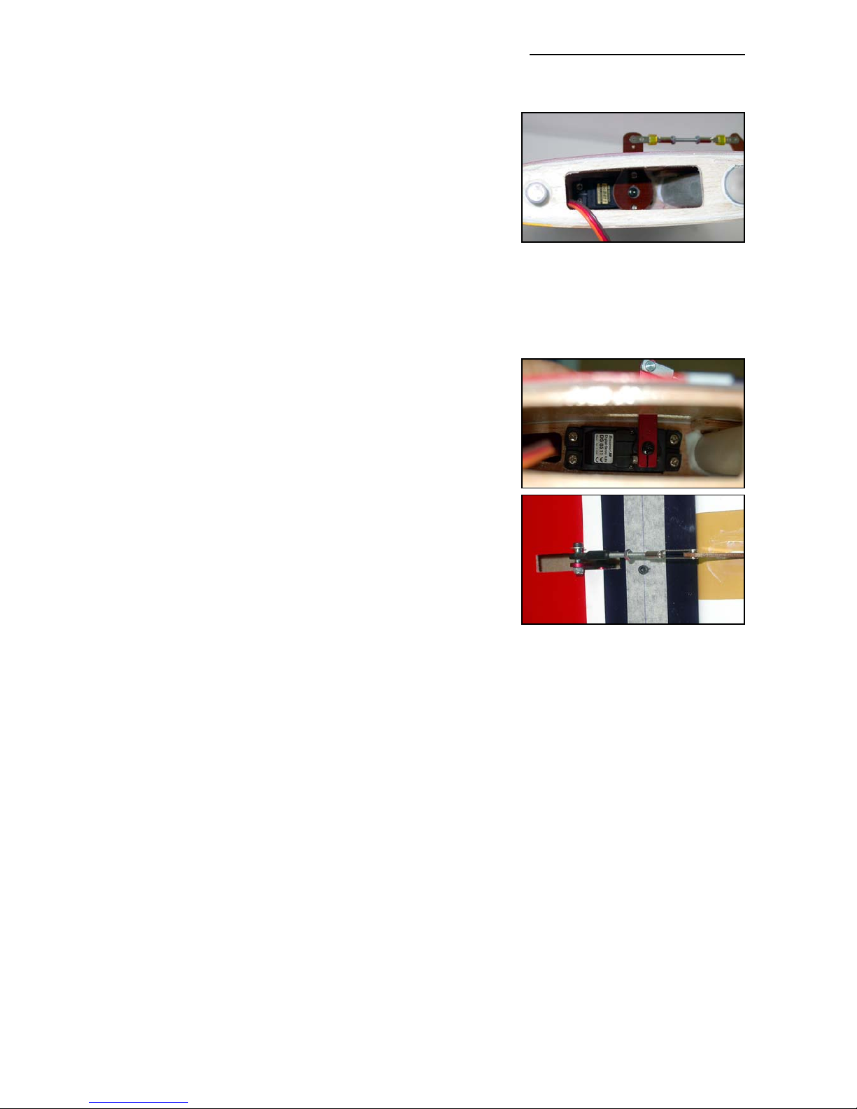
reputable accessory companies make aluminium discs and
servo arms, but you should check that the CNC machined
splines fit onto the servo output shaft tightly, with a minimum of lost movement/play.
Secure the phenolic arms to the servo output discs as follows: Fit the metal discs to the servos. Centre both elevator servos using your R/C and attach the phenolic servo
arms to the outside of the metal discs temporarily with a
couple of drops of CA, making sure that the servo arms are
both at 90° to the bottom surface of the stabs using a set
square. Then remove the arms and discs, drill through
both, and secure with at least 2 small bolts, washers, locknuts and Loctite (M2, 2/56 or equivalent). Finally add a drop
of Loctite to the bolt that secures the discs to the servos.
Use this same method to attach the phenolic extension
arms to metal discs for the aileron & rudder surfaces also.
At Composite-ARF we only use the aluminium ‘Double-Loc’
servo arms from SWB manufacturing (USA) and we highly
recommend them. These arms clamp onto the servo output
shaft with no lost movement (play) at all. These are high
quality, properly engineered arms, and are available from
many good hobby stores.
With your chosen servo arm secured to the servos, fit them
in place in the milled cutouts in the stabs and secure with
the 2.9 Ø x 13mm sheetmetal screws we provide.
It is most important that the linkage from the servo arms
is exactly in-line with the phenolic control surface horns in
the elevators, as any ‘side-load’ or ‘twisting’ could weaken
or even break them, causing flutter and destruction of your
Extra. If you have chosen to fit full metal servo arms, (eg:
SWB), you can fit a single-sided ball-link onto the servo arm to adjust the line of the linkage if
necessary - but you must not fit a ball-link to a phenolic or plastic servo extension arm, or phenolic control surface horn.
If your chosen servo arm system does not line up perfectly with the factory-milled slots for the
phenolic control horns, you can either fill the slots and mill new ones - or even pack the servo off
the rib slightly inside the stabiliser to adjust the alignment. Make up the elevator linkages from
the hardware supplied, using M3 x 45mm threaded rods, and M3 steel clevises and nuts at both
ends. If you use a full metal servo arm, then you may need to use a wider clevise with a separate pin and E-clip, because of the thickness of the arm and the sizes of the holes - as shown
on the SWB arms here. This also applies to the aileron horns, of course.
Control Horns
The slots for the phenolic elevator control horns are already partly milled in the elevators for you,
but may be adjusted or repositioned if required. Extend the slot for the elevator horn to least
20mm deep, using a Dremel mill or small Permagrit file, checking alignment with the linkage as
you work. Trim the length of one of the phenolic control arms so that the hole for the clevise is
Composite-ARF Extra 300SX (2.6m span)
16
(above) Phenolic servo arm extension bolted to metal disc on servo.
Short lengths of tube prevent clevises from opening accidentally.
(below) The alternative full-metal
SWB servo arm set-up.
(above) You can ONLY use a balllink on a full metal servo arm to
adjust linkage alignment. Do NOT
use on phenolic arms or horns
*
Page 17
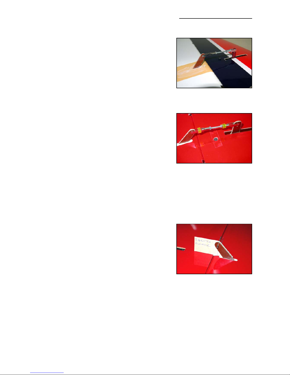
approx. 25mm from the surface of the elevator, and roughsand the part that will be glued into the balsa block inside
the elevator. Ideally the hole in the horn for the clevise
should be exactly perpendicular to the centre of the hinge
tube.
Wax the area with clear car wax, cover with a layer of plastic parcel tape over the area of the milled slot, re-wax the
tape carefully, and then cut through the tape with a very
sharp knife to allow the horn to be glued into the slots. The
tape stops excess glue getting on the painted elevator, and
makes the clean-up easy and quick.
Make up the servo linkage from the hardware provided, and
connect your servo arm to the control horn, which helps to
hold the horn in exactly the correct position while the glue
cures. Fill the slot in the elevator with slow epoxy and
micro-balloons (min. 30 minute cure), or a thixotropic resin
like Loctite Hysol 9462, insert the horn, and then wipe away
excess glue. Check that it is aligned perfectly with the linkage, the clevise hole is 25mm from the surface of the elevator, and is perpendicular to the hinge axis. View from the
back or front to check that the horn is at 90 degrees to the
surface of the elevator. See photo P6 for ideal linkage.
When cured, remove the plastic parcel tape and make a
plywood template, as shown right, so that you can copy the
position to the horn on the other elevator. In this way you
will get exactly equal elevator throws without lots of mixing
and linkage adjustment when setting up your plane. You
can make the template from scrap plywood, and use an old
1.5mm (1/16”) drill bit to insert into the clevise hole, secured
with a drop of CA. Using the template, glue the horn into the
other elevator in exactly the same way.
The linkages between the servo arms and elevator horns
are made from the 45mm x M3 all-thread, with 2 steel clevises and 2 x M3 nuts for each stab. ‘Loctite’ the quick-link
and lock-nut on one end of each linkage. If using full metal
arms, like the SWB arms shown, you will need to replace
the steel clevise on the servo end with a larger type as
shown here. If using clevises with aluminium pins in aluminum servo arms, we highly recommend that you apply a little grease on these joints to give smooth movement and prevent any
inclination of the aluminium pin to bind in the servo arm hole.
Use this same technique, as above, with a template, for the inner/outer aileron horns.
Throws
If you need more travel on the elevators than the factory assembly allows (about 40°) you will
need to increase the length of the slots in the composite/balsa false leading edge of the elevators with a small file. The outer 2 slots in particular will need to be longer, and you can extend
them almost right out to the composite skin.
Composite-ARF Extra 300SX (2.6m span)
17
(above) Shows the stab retaining
bolt, with clear tape over it to prevent it coming out in flight. The
small pieces of tubing stop the
quick-links from opening.
(below) Elevator horn alignment
template from scrap plywood. Line
is hinge axis. Use for both elevators
to ensure same throws.
(above) Use parcel tape to protect
paint & make easy clean-up when
gluing in all control surface horns.
*
Page 18
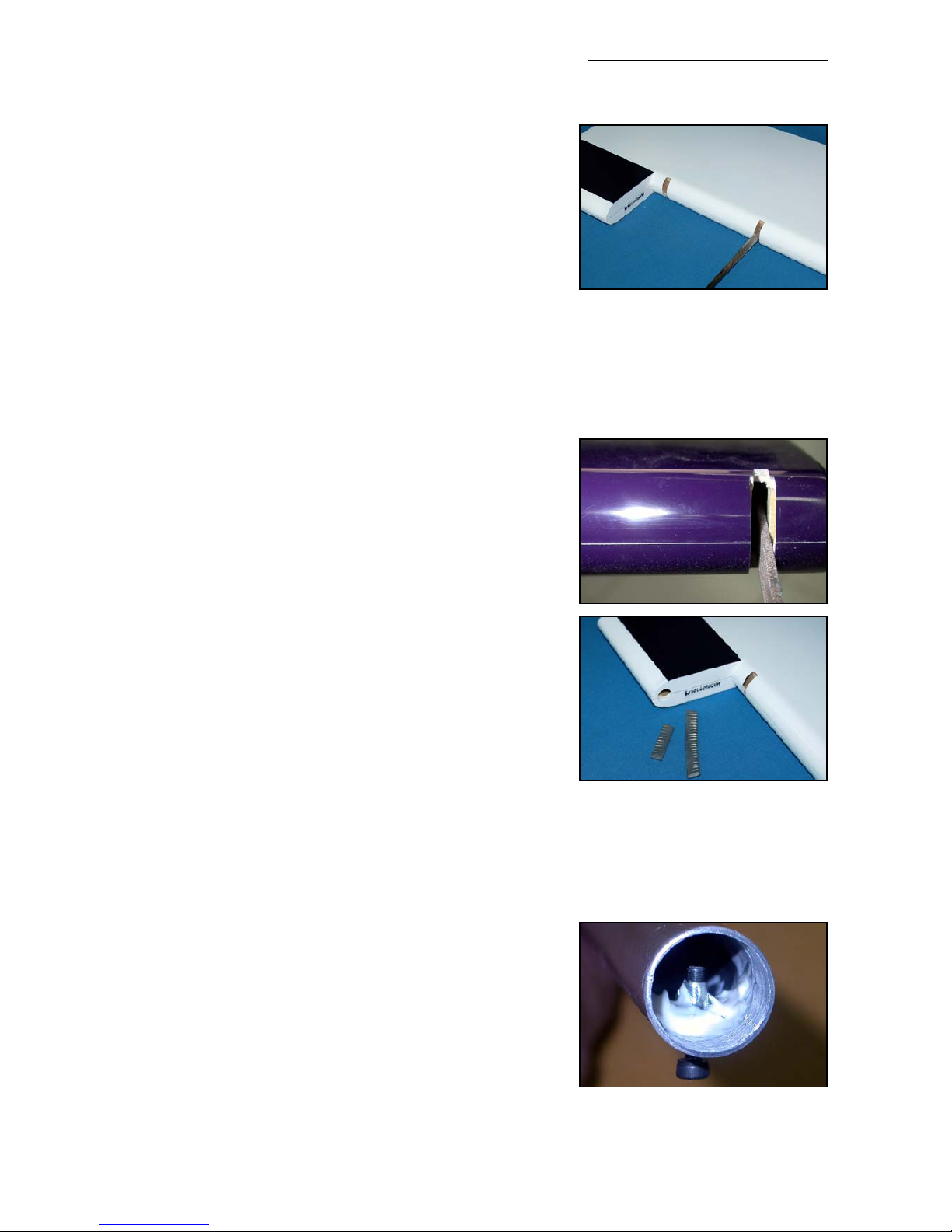
Unfortunately it’s not possible for us to mill these slots
longer during manufacture - as the L.E. spar would fall
apart on the CNC milling table. However, this is a very quick
job with a Permagrit file, or similar (see photo right). You
can easily achieve 50 degree throws if you wish.
Note: Several photos of the stabs in these instructions
show the 1.5” SWB arms on JR8511 servos, with the clevise in the outer hole - and this was used for extreme testing of the model and stabiliser servo system, with more
than 50 degrees throw possible.
Static Balance
We advise that you partially static-balance the elevators by
gluing 15 - 30 grams (0.5 - 1 ounce) of lead inside the
mass-balance area in each elevator half, which helps to
prevent any chance of flutter that could destroy your Extra.
How much you can add depends on your motor weight, but
even adding 20 grams (0.7 ounce) will increase the safety
factor. With a DA-100 you can definitely afford to add 30
grams to each elevator. Just drill a small hole in the inner
leading edge of each counterbalance, and glue some strips
of lead in with epoxy & micro-balloons mixture. Cover the
hole with a sticker.
Stab Tube
The last job is to fit the M3 stab retaining bolts. Inside the
stabs you will see the small ply reinforcement plates
between the spar sleeve and the bottom surface of the
stab. Mark the bottom of both stabs in the centre of this plywood. Install the aluminium tube into 1 stab, and drill a
2.4mm hole right through the stab surface, the plywood
plate, sleeve and the 20mm aluminium tube. The centre of
the hole will be 33 - 34mm from the T.E. Thread the hole
with an M3 tap and secure it with an M3 x 16 bolt. To be
really safe, you can glue an M3 blind nut (included) inside
the spar tube, with some 30 minute epoxy and micro-balloons. Wax or oil the bolt first! Fit both stabs to the fuselage,
check that they fit tightly to the fuselage at the roots, and
then drill the hole in the other stab and spar tube, and tap
the thread as before. Counterbore the holes in the bottom
surface of the stabs for the boltheads so that they sit flush
on the small plywood plates.
TIP: Try to always leave the stab tube fixed into one stab,
and never remove that one bolt, as it is difficult to find the
right position for the stab tube again if it is removed from
both stabs!
Composite-ARF Extra 300SX (2.6m span)
18
(above/below) You can increase
available throws by lengthening
the slots in the leading edge of the
elevators, especially the 2 outer
slots. Use a fine flat file, such as a
Permagrit, and be careful not to
make the slots any wider.
(above) Glue 15 - 30 grams lead
into the leading edge of the elevator mass-balance to help prevent
any chance of flutter.
(below) M3 blind nut glued into
elevator spar tube.
Page 19
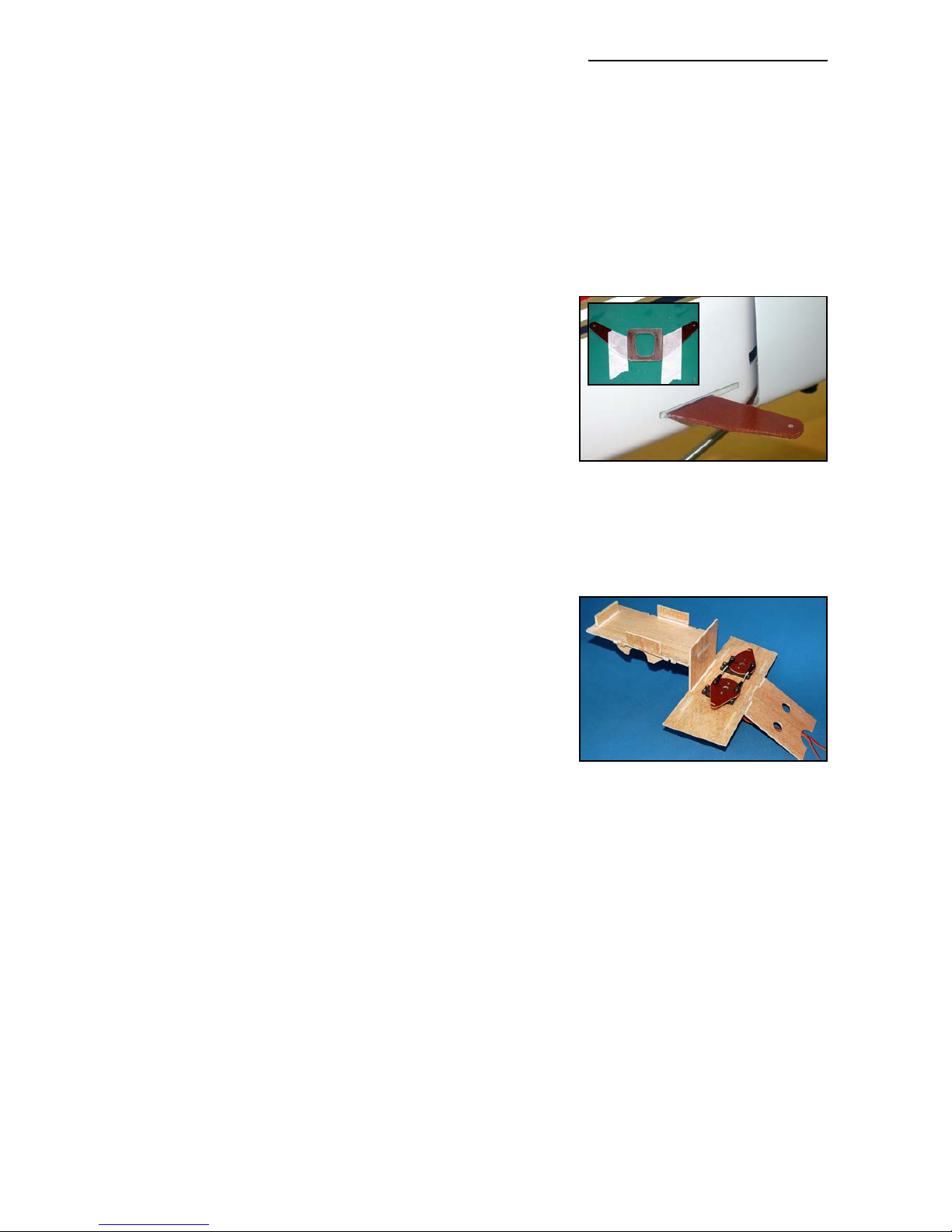
Rudder
Trial fit the the double-sided phenolic control horn in the slot that is already milled in the base of
the rudder, mark the central part that will be glued in, and scuff it well with coarse sandpaper.
There is a balsa block underneath the horn position inside the rudder, and this should also be
scuffed with sandpaper or a small file. Adjust the milled slot in the rudder so that it is a little higher than the phenolic control horn thickness, so that all the glue is not scraped off the horn when
you insert it into the rudder !
Cover the rudder both sides around the slot area with
masking tape, wax the area, and then cut through the tape
to expose the slot with a sharp knife - in the same way as
described for the elevators. This makes it easy to clean off
excess glue afterwards. Glue the horn in position with slow
(min.30 minute) epoxy & micro-balloon mix, making sure
that it is perfectly centred and level in the rudder. When the
glue has cured, fit the rudder to the vertical stabiliser with
the 2mm steel hinge wire. Sand a small chamfer on the end
of the hinge wire for easier insertion through the phenolic
hinge posts, and if it is too tight use a little grease on the
wire. Check for smooth movement. You can increase the
lengths of the slots in the rudder L.E. in same way as the
elevators to gain extra throw if necessary.
The rudder servo mounting plate (and tank base) should be
installed in the plane after the engine and exhaust system
mounting are completed, but it is easier to assemble the
parts and install the servos outside the model now.
Glue the 2 milled plywood reinforcing pieces underneath
the servo cutouts in the balsa plate with CA, and glue the
plywood reinforcement onto the underside of the tank tray
(see also photo P8). Prepare, sand and assemble the other
milled composite balsa parts as shown above, using thin CA. Check fit of the complete assembly in fuselage, and then apply a fillet of 30 minute epoxy to all joints and edges. It’s a good idea
to seal all bare edges of the fuel tank base with a coat of laminating epoxy now, or even thin CA,
in case of fuel leaks. Adjust the height of the vertical balsa bulkhead between the tank base and
servo tray, if necessary, so that the tank sits level when the plane is in level flight. The angled
balsa plate behind the rudder tray is optional, and can be used for locating your Powerbox or
Receiver if you wish. (photo P9)
Servos
The recommended choice of servos is similar to that for the elevators, either a pair of
JR/Graupner 8411/8511/8611’s or a pair of Futaba S9351’s.
Servo arms
The supplied ‘pear-shaped’ phenolic rudder servo output horns must be bolted to 1” or 1.25”
diameter metal servo output discs in the same way as the elevators. Please do not use the standard plastic discs for this, as there is a chance that the internal plastic splines can be stripped
by the current hi-torque servos - causing instant rudder flutter, and probable loss of your plane.
Fit the 2 rudder servos into the tray, with the output shafts nearest to the tailplane, and screw
into position using the 2.9mm Ø x 13mm long sheet-metal screws supplied. Fit the metal servo
Composite-ARF Extra 300SX (2.6m span)
19
(above) Scuff up the gluing surfaces on the rudder horn and glue
into the slot in the rudder.
(below) The Tank base/Rudder tray
is assembled from the milled parts
included in the kit.
Page 20
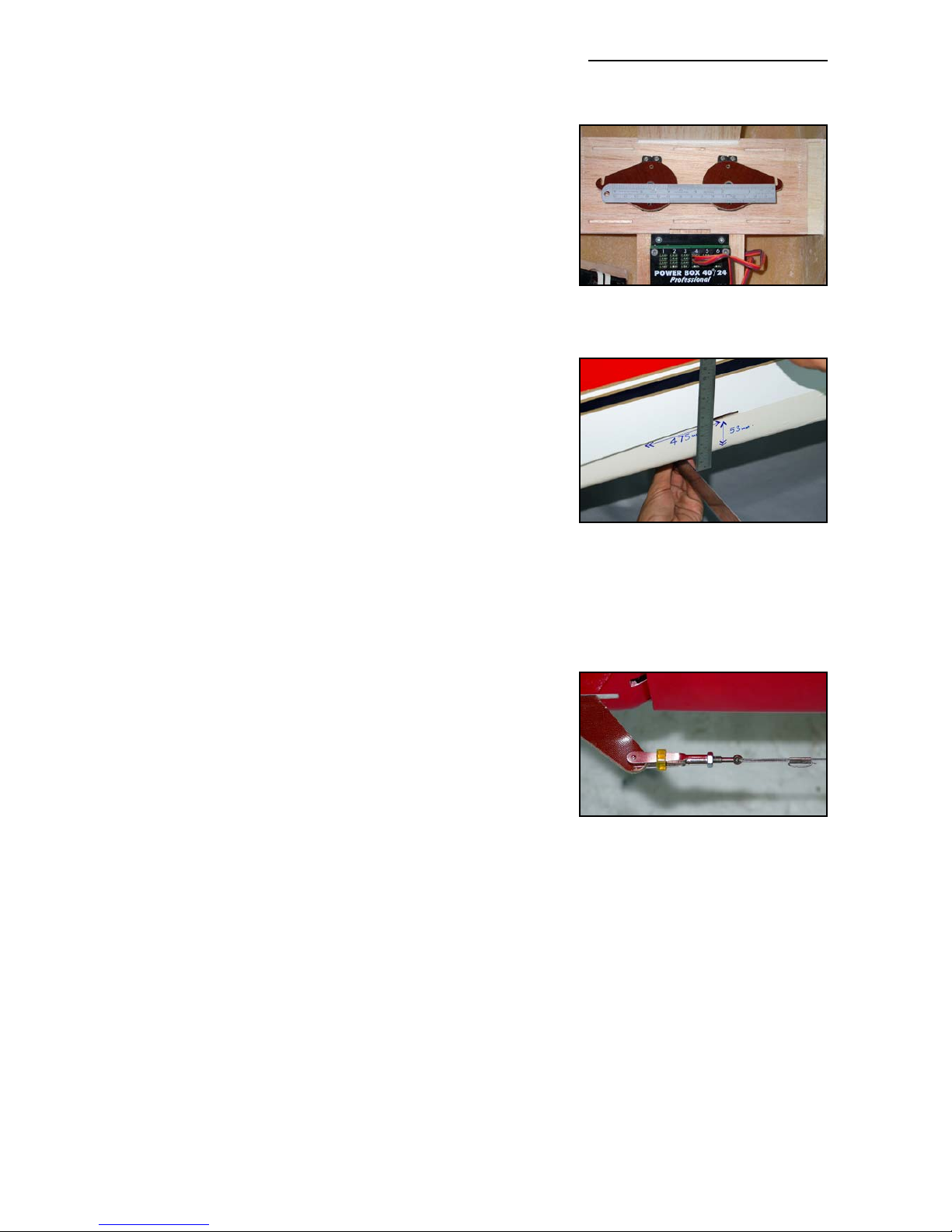
discs, and centre both servos using your R/C. Rough sand
and clean the bottom surface of the 2 phenolic horns, and
the top of the metal discs.
With the R/C still switched ‘ON’ place the C-ARF rudder
servo horns on top of the output discs, with both ‘hooks’
facing forwards, and align them exactly using a steel ruler
as shown in the photo above. Make sure that the back of
the hook slots and the output disc securing screws are all
perfectly in line. Tack glue the phenolic arms on top of the
output discs with a couple of drops of thick CA. When the
glue has cured, remove the arms and discs, drill through
both and secure with at least 2 small bolts, washers, locknuts and Loctite (M2, 2/56 or equivalent). Finally add a drop
of Loctite to the bolts that secure the discs to the servos.
Make up the linkages between the servos from the M3 balllinks and threaded rod included, as shown. Secure just one
of the linkages between the phenolic arms, with the M3 x
16 bolts through the milled holes, with lock-nuts underneath. Adjust the length of the linkage very carefully until so
that there is minimal buzzing or humming from the servos
at idle, or at full throw. When satisfied, add the other linkage and follow the same method of adjustment. (photo P9)
After the motor and exhaust system is finished, glue the
competed tank base/rudder servo tray into the fuselage
with 30 minute epoxy and micro-balloons mixture. Make
sure to get a good glue joint between the supports on the
bottom of the tank base and the wing tube sleeve. Install
the wings on the fuselage during this operation, to make
sure you cannot deform the fuselage. Scuff up the fuselage
where the parts will be glued in, and reinforce these important joints with short lengths of the 1” fibreglass tape supplied, using laminating epoxy. (photo P10)
With the rudder servos fitted in the recommended position,
then the centre of the slots that you must cut for the parallel pull-pull cables to the rudder is
475mm (18 3/4”) forward of the back edge of vertical fin, and 53mm (2 1/8“) up from the bottom
of the fuselage. Cut out a small slot first with a very sharp knife, check the position using the pullpull wire, and then adjust and open up the slots with a small file as needed. The slots need to be
about 3mm high and 50mm long. If you prefer to ‘cross’ your rudder cables, then these slots
should be 175mm forward of the fin TE, and approx. 33mm above the bottom of the fuselage.
Make the pull-pull wires from the hardware supplied, with a loop at the front that goes over the
hooks on the output arms, and a quick-link with threaded extender (turnbuckle) and locknut at
the rudder end. Pass the closed loop cable through the supplied ‘crimping tubes’ 2 times before
squashing flat with pliers (see photo). Make sure that the wires are tight, and check and adjust
after the first few flights as the cables straighten out. Even a small amount of slop will prevent
your Extra from perfect tracking. You can glue a very small scrap of ply or balsa across the front
of the slots on the servo arms with a drop of CA to prevent the wires coming out of the slots accidentally.
Composite-ARF Extra 300SX (2.6m span)
20
(above) Centre the servos with
your TX & align the horns very carefully with a steel straight edge.
(above) Slot positions for parallel
rudder cables.
(below) Pass rudder cable thru’
crimping tubes 2 times for safety,
and prevent all clevises from opening with small pieces of tubing.
Page 21
Wings
The wings are 95% finished at the factory, and have
already been installed on your fuselage to set the alignment. Slide the wings onto the wing tube and check for a
perfect fit. You can sand the wing roots a little if needed.
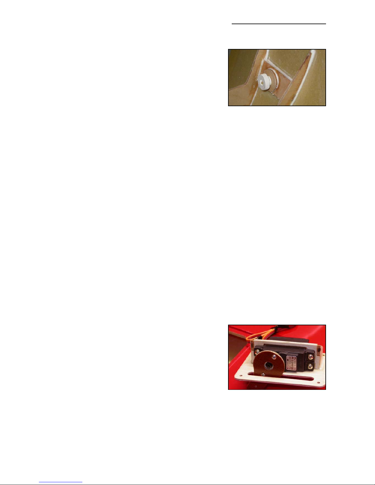
Fit the 4 plastic wing retaining nuts onto the M6 threaded
aluminium wing dowels. We have already installed plywood
reinforcement rings inside the fuselage for the back nuts,
but you need to glue on the 2 small rings of milled 3mm plywood for the front nuts, parallel to the back surface of the plastic nuts. Sand a chamfer the plywood rings so that they are only 0.5mm thick at the bottom edge. Use 30 min epoxy and microballoons to glue in place, and fit the front nuts loosely while curing to set the alignment. Fill the
gap between the top of the rings and the plywood plates on the fuselage side with epoxy/micro
mixture. Don’t forget to wax or oil the front dowels and M6 threads first to prevent them being
glued in permanently!
Each wing has 2 servos for each aileron, and the openings for the servos and hatches are
already pre-cut in the wing for you, and supplied with matching servo covers and milled plywood
servo mounts (photo P11). Sand the inside surface of the servo hatch covers very well, and the
milled plywood parts that make up the servo mounts to make sure you have a good gluing surface. This is very important ! We highly recommend that you mark the 4 hatch covers now so
that they are always fitted in the correct positions (eg: Starboard Inner/Outer etc).
Wing Tube
The wing tube is a 40mmØ T6 alloy tube, which slides inside a fibreglass tube in each wing, and
it should be 1040mm long. Please check the length to make sure that it passes through both ply-
wood ribs in the wing, that are about 350mm from the root, otherwise the wing could fail in flight.
Important: Due to manufacturing tolerances on some early kits it is possible that the fibreglass
tubes are a little bit long, or the wing tubes a little bit short, allowing the wing tube to slide into
one wing further than the other - and then the alloy tube will not pass thru the both plywood ribs.
In this case, you must glue a 10mm thick scrap balsa block into the outer end of both fibreglass
tubes to make sure that the wing tube stays centred, and both ends pass thru’ the plywood ribs.
Servos
The choice of servos is similar to that for the elevators, a
pair of JR/Graupner 8411/8511/8611’s or a pair of Futaba
S9351’s in each wing. If using 8511/8611 servos you will
need to sand the inside of the plywood servo mounts about
0.5mm bigger all round for a good fit.
Install the servos with the output shafts towards the leading
edge. The ailerons have enough torsional flexibility to prevent servo damage if each pair is not perfectly matched.
Servo arms
To obtain the maximum possible aileron throws quite long servo output arms are needed (30 35mm/1.25 -1.5”). In the kit we supply phenolic servo arm extensions for this purpose, which can
be fitted onto your servo output discs to achieve the throws. However, it is mandatory to secure
Composite-ARF Extra 300SX (2.6m span)
21
(above) Plywood rings glued in
vertically for front nuts with thick
mixture of epoxy/micro-balloons.
(above) Phenolic servo arm extensions may only be fixed to metal
servo output discs.
Page 22
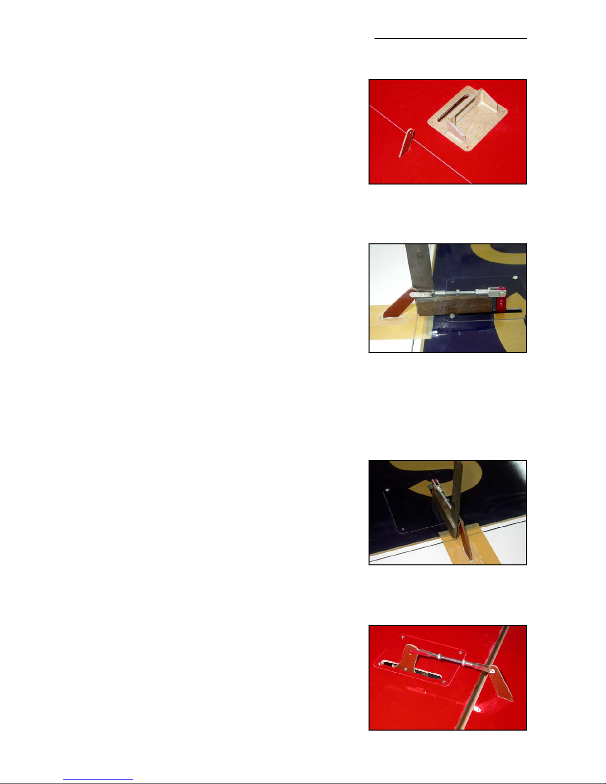
these to metal servo output discs, or to use full metal servo
arms (like those shown here from SWB) - and not the standard plastic output discs supplied with the servos. Secure
the phenolic servo arm extensions to the metal output discs
in the same manner as used for the elevators, centering the
servos with the R/C and making sure that all 4 arms are all
at exactly 90° to the side surface of the servos.
Assemble the servo mounts from the 3 CNC milled plywood
parts supplied for each servo, using thin CA, as shown in the
photos here, and P12. Fix the servos into the mounts with
the 2.9mm Ø screws provided in the kit, and secure your
chosen type of servo output arm to the servos.
Place the servos in their mounts on the inverted hatch covers to check the alignment so that the servo output arms
are exactly in-line with the pre-milled slots in the wing for
the control surface horns. The same principles apply here
as for the elevators, and you can adjust the slots in the
ailerons, or the slots in the hatch covers slightly, if necessary, depending on your servo arm type. Tack the mounts
in place onto the hatch covers with a drop of thin CA.
When satisfied, glue the servo mounts to the hatch covers
permanently, with thin CA, and then remove the servos,
and reinforce the glue joints between the servo mount and
the servo cover plate with slow (at least 30 minute) epoxy
and milled fibre, with a nice glue fillet all around. These are
important glue joints!
Each servo hatch is fixed to the underside of the wing with
of the 4 sheet-metal screws provided, Ø2.9 x 10mm. These
servo mounts allow you to change a servo within a few minutes, if needed, easily within the time between 2 flying
rounds of a contest.
Control Horns
The slots for all 4 phenolic control horns are already partly
milled in the ailerons for you, but may be adjusted if
required. Extend the slots for the horns to least 20mm
deep, using a Dremel mill or small Permagrit file, checking
alignment with the linkage as you work.
Fit just one inner control surface horn to start with, using the
same method as described for the elevators. Trim the
length of one of the phenolic control arms so that the hole
for the clevise is approx. 23mm from the surface of the
aileron, and rough-sand the part that will be glued into the
balsa block inside the aileron. Ideally the hole in the horn
for the clevise should be exactly perpendicular to the centre of the hinge axis on the top of the wing.
Use a layer of parcel tape and clear wax to protect the
aileron surface. Install the corresponding servo and hatch,
Composite-ARF Extra 300SX (2.6m span)
22
(above) Clevise hole for inboard
horns should be 23 - 24mm from
aileron surface, and perpendicular
to the aileron front edge.
(below) Make sure control horns
are perpendicular to aileron surface and parallel to servo arm.
(above) Adjust position of servo
mounts on hatch covers so that
servo output arms align exactly
with phenolic aileron horns.
(below) View of aileron linkage,
with servo using metal disc, C-ARF
phenolic extension arm and the
included hardware.
Page 23
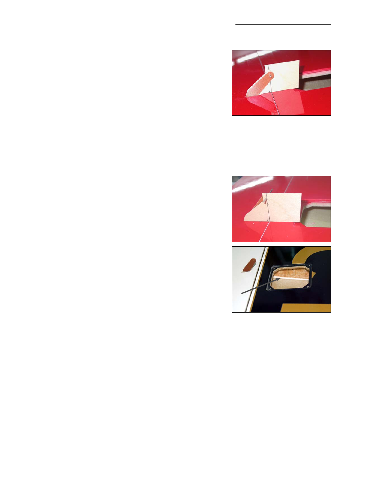
make up the linkage from the M3 clevises, 45mm long
threaded rod and nuts provided - and connect the linkage
from the servo arm to the control surface horn while the
glue is curing to help maintain perfect alignment. When
cured, remove the plastic parcel tape and make a plywood
template, as shown right, so that you can copy the position
for gluing in the inboard horn on the other aileron.
The 2 outer control surface horns are completed using the
same method, first finishing one, and then using a template
to glue in the other one. However, the distance between the
clevise holes in the phenolic horns to the hinge axis line (top
surface of the wing) should be the same for the inner and
outer horns. However, because the wing/aileron is 6mm
(1/4”) thinner at the position of the outer horns, these outer
horns must project of the aileron 6mm more than the inner
horns. This is to ensure that the aileron servo throws are
similar and that the servos don’t ‘fight’ against each other.
Because of the difference between the inner and outer
horns, the easiest method is to make the template for the
inner horns and glue them both in place first, and then drill
another hole in the same template 6mm higher, exactly on
a line drawn on the template that is perpendicular to the
hinge axis - and use this for the outer horns.
Note: There are a few early slightly different versions of the
300SX wings which do not have a balsa sub-rib outboard of
the outer aileron servo position. Although this rib is not
structurally necessary, if your wings do not have this rib it is
a good idea to glue a 70mm (3”) long piece of 3mm balsa
immediately outside the servo cutout between the top and
bottom wing skins to prevent damage to the wing in the
case of flutter.
Sand the inside surfaces of the wing, cut a piece of scrap 3mm balsa, with the grain vertically,
and glue inside the wing with 30 minute epoxy and micro-balloons mixture against the edge of
the plywood hatch reinforcement. This part is shown with an ‘arrow’ in the photo right.
Engine and Exhaust Installation
We strongly advise you to complete the motor and exhaust installation before the fuel tank base
and rudder servo tray are permanently installed, as it provides much easier access.
The most commonly installed motor in our 2.6m Extras seems to be the DA-100, very often with
a pair of MTW TD75k canisters - and we have shown photos of the installation of this popular
set-up below. However, please note that all of those photos show the installation in one of our
original 2.6m Extra 330L’s (Futaba scheme), but it is almost identical - so please don’t get confused !
For the 300SX prototype we chose to use a single-cylinder 3W 80cc Xi, and single ‘Greve’ tuned
pipe set-up, to show a lightweight and lower cost option. This has proved to be a very nice com-
Composite-ARF Extra 300SX (2.6m span)
23
(above) The aileron horn template
used to position the inner horns
for gluing in place. The line is perpendicular to the hinge axis.
(below) Same template, with an
extra hole drilled exactly 6mm
higher, for installing outer horns.
Page 24
bination, having plenty of power - and a weight reduction of
about 800 grams over the DA-100 version. Full details of
this installation are also described below. All photos of the
3W motor are shown mounted on the 300SX (Patty
Wagstaff scheme). Any similar 75 - 85cc single-cylinder
motor could also be used, for example the ZDZ 80 or the
EVO80.
The only major engine mounting difference between the
300SX and the 330L is that the firewall on the 300SX is
approx. 30mm further back from the front of the cowl, to
allow for longer motors, and that the complete motordome is an integral part of the fuselage molding - which
saves weight, increases rigidity and ensures that the
alignment of the firewall is more accurate.
The front face of the molded motor-dome/firewall on the
300SX is set at 0 degrees downthrust, and has 2.5
degrees of sidethrust built in to to it. Therefore you only
need to secure your motor parallel to the firewall, and so
that the spinner is central with the cowling, and your
thrustlines will automatically be very close to optimum. At
most you will need to add a couple of washers behind the
motor standoffs to have a perfect thrustline set-up.
Whichever motor you are using the vertical location of the
centre of the motor on the firewall can be set as follows:
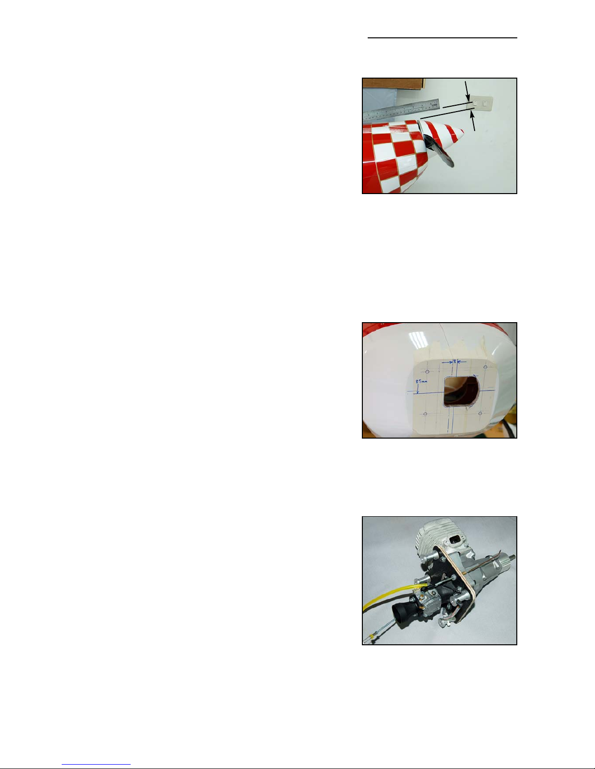
Lay a steel straight-edge on top of of the fuselage (on the
joint seam) as shown in photo P13. The offset between the
radiused part at the front top of the cowl and the straight
edge is 20mm (photo right). The top of the spinner should
be about 5mm below the top of radiused part of the top of the cowl. Therefore, if you are using
a 120mm (4.75”) diameter spinner the horizontal centreline that the engine should be mounted
on is 85mm (half of 120 + 5 + 20mm) below this straight-edge. Of course, if your spinner is Ø
125mm, then this centreline will be 2.5mm lower, etc., pro-rata. Mark the horizontal centreline
(for your choice of spinner diameter) on tape on the front of the firewall now, making sure that
the line is horizontal by eyeing thru’ the steel ruler and the
wing tube.
The side-to-side location of the centre of your motor is also
easily set. It is 8mm to the (pilots) left of the central seam
of the motor-dome. (see photo right). With the motor
mounted centred on these 2 lines, with 4 equal length
standoffs, the centre of the spinner will be centred on the
front of the cowling.
3W 80cc Xi.
For this set-up we used a C-ARF 120mm diameter carbon
spinner (# 810103), a Greve tuned pipe (# 910200), with
a custom welded manifold and a Mejzlik 27 x 10 carbon 2blade prop.
Composite-ARF Extra 300SX (2.6m span)
24
(above) The top of the spinner
should be 5mm below the
radiused front edge of the cowl,
which is 20mm below the straight
edge laid flat on the fuselage.
(below) The side-to-side centre of
the motor should be 8mm to the
pilots left of the motordome seam.
The cutout shown here is for the
rear-mounted 3W carburettor.
(above) The 3W 80cc Xi motor,
attached to 6mm carbon/plywood
plate, with 30mm long aluminum
stand-offs - also showing throttle
and choke linkages.
20mm
Page 25
3W state in their instructions that the engine must not be
mounted directly to metal stand-offs, as unequal lengths, or
unequal tightening of the bolts could cause crankcase distortion. Therefore we made a mounting plate from 2 layers
of 3mm carbon-composite plywood, glued together with
24hr laminating epoxy, and bolted the engine to this with
M5 bolts, washers and lock-nuts. Then the carbon-ply
mounting plate was secured to the firewall using 4 standoffs of exactly 30mm length, with the M6 bolts and washers
included in the hardware.
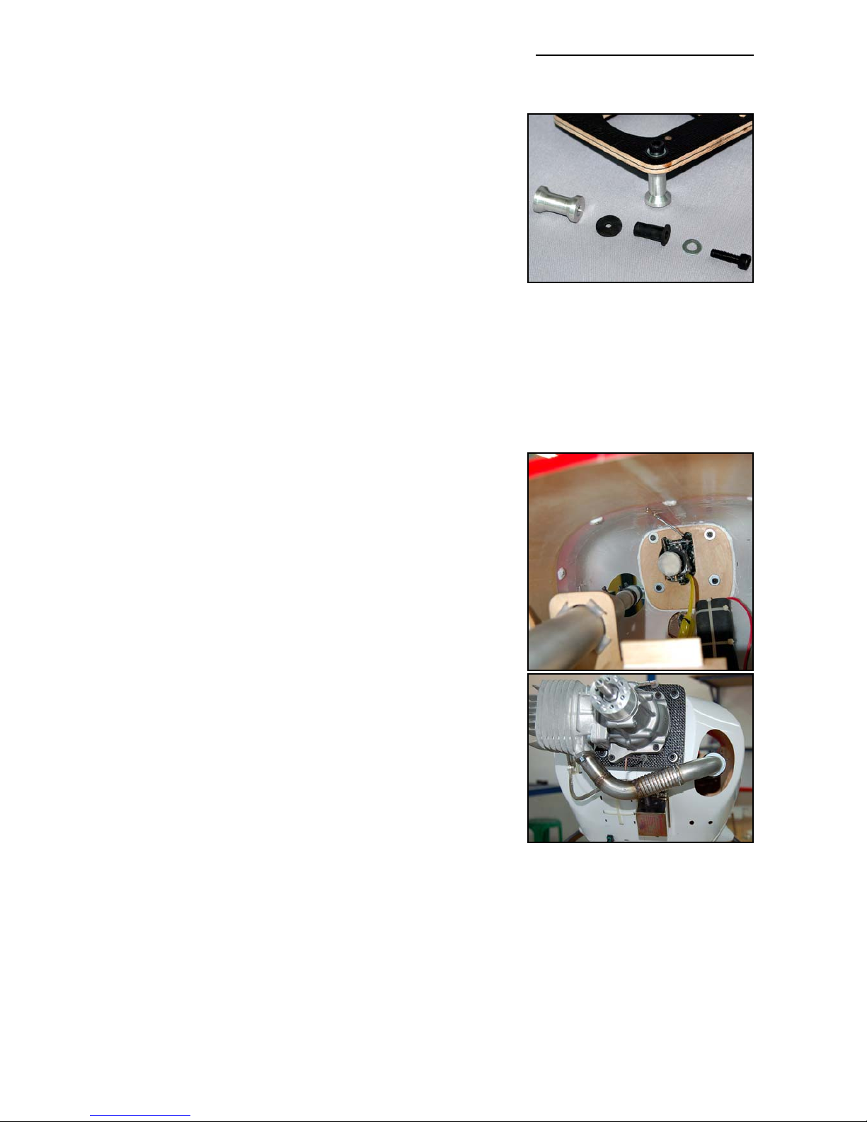
As it is a single-cylinder engine we chose to use anti-vibration mounts in the carbon-plywood mounting plate, made
from the usual ‘well-nuts’ (or short lengths of hard silicone
or rubber tube) to isolate the mount from the firewall, and it
certainly does help to prevent transmission of vibrations to
the airframe.
Four 9.5mm diameter holes were drilled in the carbon plate
for the M6 bolts, and the well-nuts were inserted from the
front face, with the excess length trimmed flush with the
back surface. The M6 bolts should be a fairly tight fit inside
the well-nuts or tubes used. If you use short lengths of hard
rubber or silicone tube, instead of the well-nuts, then you
will need to add a rubber washer on the front face, instead
of the flange on the well-nuts. Rubber washers can be easily cut from motorcycle tire inner tube with a sharpened
brass tube. An M6 steel washer is used on the front face,
under the head of the M6 bolt.
On the back face, between the carbon/ply plate and the aluminum standoffs, another 16mm (5/8”) Ø rubber washer
was added. Use Loctite on the M6 bolts that pass thru’ the
isolation mounts in the carbon plate to secure them firmly
into the stand-offs - and be careful not to tighten the bolts
up so much that you completely compress the rubber and
eliminate the anti-vibration system! The photo (above)
shows the order of assembly of the parts.
You need to cut a hole in the firewall for the rear-mounted
3W carburettor, and the 3W instructions include a full-scale
drawing of the engine mount positions and carburettor
which is very useful when making the mounting plate and
carb cut-out.
We highly recommend that you fuel-proof all bare wood
inside the motordome/tank base area with a thin coat of
laminating resin, as these carbs can spray a thin mist of gas
(petrol) from the venturi.
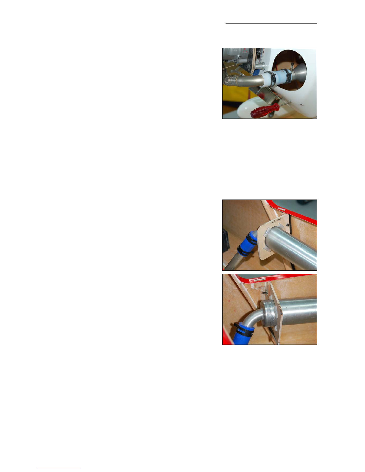
The header/manifold was custom-made to suit this installation, but it is quite long, which meant
that we needed to shorten the entry into the Greve tuned pipe by 45mm to correct the tuned
length.
Composite-ARF Extra 300SX (2.6m span)
25
(above) 3W 80cc Xi motor
installed, with custom header and
Greve tuned pipe. Note position
of Ignition unit, and cable -ties
which secure the 2 receiver Nicads
inside the motordome.
(above) Shows the order of assembly of the anti-vibration mounts in
the carbon-ply mounting plate.
(below) Standoffs are bolted thru’
the firewall with the supplied M6 x
20mm allen bolts & washers. M6 Tnuts are also included in the hardware, which can be used with
some engine mount types.
Page 26
After first trimming flights we added a single thin 6mm ID
washer behind the left side stand-offs and the motor dome,
to increase the sidethrust very slightly - and also a thin
washer behind both lower stand-offs which actually gave
the very slight upthrust (approx +0.25 degree) required for
perfect neutrality.
Tuned Pipe.
Although a bit more complicated to install than a canister
muffler, we fitted a tuned pipe as it gives some increased
power, improved throttling characteristics and reduced
noise levels - especially important in Europe where we
have quite strict laws on this.
The pipe is supported at the front and back on 2 cnc milled
plywood tuned-pipe mounts which are included in the kit (to
suit Ø 49mm pipes), together with enough of the hard silicone tube to make the isolation mounts. Cut the silicone
tube into 20mm lengths and insert in the milled slots as
shown in the photos below/right. The front pipe mount is
secured to the front face of the plywood landing gear mount
with 2 sheetmetal screws (Ø 3.5 x 18mm), access is with a
long X-head screwdriver thru’ the 2 small holes seen lower
right side in the photo above and P16.
The rear mount must be secured to a 3mm thick plywood
reinforcing plate glued onto the side of the fuselage, as
shown - and you can use two of the M3 bolts and T-nuts
included in the spare hardware pack for this. We reinforced
the fuselage at this point with a few carbon rovings, but in
retrospect this was not necessary with the relatively low
vibration levels experienced. Maintain at least 6mm (1/4”)
clearance between the bottom of the tuned pipe and the
fibreglass sleeve around the wing tube, and check to make
sure you can still access the front M6 plastic nuts used to
secure the wings to the fuselage.
Make sure that the tuned pipe cannot move forward (or
backwards) and touch against the end of the manifold, as
the metal-to-metal contact could cause terminal R/C interference! 2 small sheet metal screws through the teflon joiners and pipe/manifold side walls prevent this. The 3W instructions include a full-scale drawing of
the engine mount positions and carburettor which is very useful when making the mounting plate
and carb cut-out.
You can see in photos P20 and P24 that we installed a thin balsa-composite plate against the
left side of the fuel tank, & also above the left hand rudder phenolic servo arm, to prevent any
possibility of heat damage.
Canister mount
Depending on your header, you should find that a single canister (MTW TD110K shown here)
will fit in front of the wing tube sleeve, but you will probably need put the canister on the oppo-
Composite-ARF Extra 300SX (2.6m span)
26
(above) Prevent the canisters or
tuned pipe moving forwards or
backwards with 2 small sheetmetal
screws thru’ the teflon coupler(s).
Screwdriver is for tightening sheetmetal screws in front mount.
(below) Rear pipe mount is
secured to a 3mm thick scrap plywood plate glued securely to the
fuselage side.
Page 27
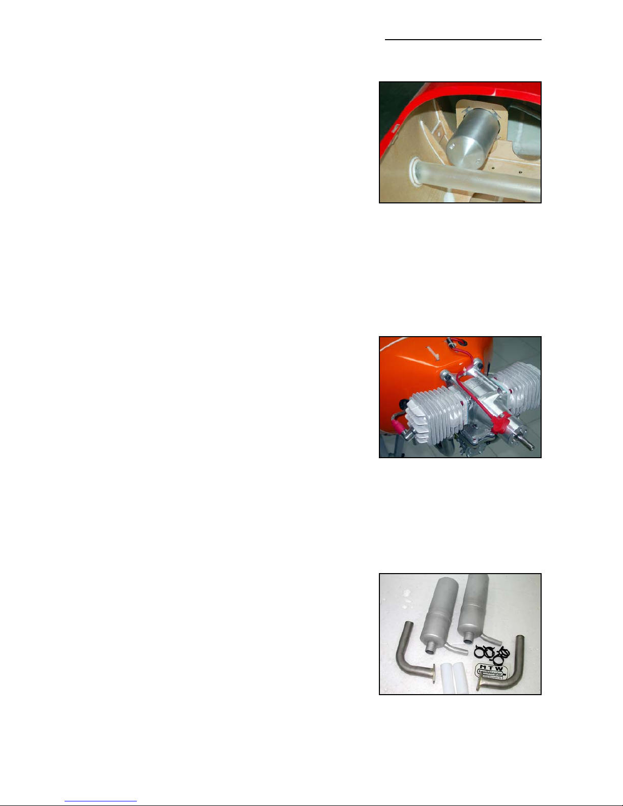
site side of the fuselage to the cylinder - and use a ‘crossover’ header to give you enough length.
Included in the kit is one cnc milled plywood mount to suit
the TD110K, or similar 80mm diameter canister. Insert
20mm lengths of the hard silicone tube in the corner slots
to make the isolation mounts, in the same way as shown for
tuned pipe mounts. The plywood mount can be screwed to
the front of the landing gear mount bulkhead with 2 of the
Ø3.5 x 18mm sheetmetal screws included in the hardware
pack.
Enlarge one of the semi-circular cutouts in the plywood
bulkhead at the front of the landing gear mount as required.
Make sure that there is at least 6mm (1/4”) clearance
between the bottom of the canister and the top of the carbon landing gear - as the heat could damaged it with
extended exposure to the high temperatures. You can protect the top of the carbon, if needed, by adding a thin ‘sacrificial’ plywood plate, glued to the top of the carbon with
clear silicone adhesive.
Desert Aircraft DA-100
The DA-100 installation and set-up uses the same principles and motor centreline positions as detailed above.
Because it is a twin-cylinder motor it has lower vibration levels and it is not necessary to incorporate an anti-vibration
mount. The motor fits fully enclosed in the cowling.
The photos below show the DA-100 installation in one of our 2.6m 330L’s (Futaba scheme) but,
of course, as the motor-dome/firewall on the 300SX is 30mm further back you will need to use
30mm long engine standoffs to ensure a 5 - 6mm gap between the rear face of the spinner- backplate and the front of the cowling - instead of the short stack of washers shown here. Other than
this the installation is identical.
Mark the horizontal and vertical motor centreline positions accurately on the front of the firewall
in same manner as described at the beginning of this section, dependant on your spinner diameter. The 4 mounting holes for the DA-100 are 70mm apart
horizontally, and 80mm apart vertically. Mark half of these
dimensions equidistant either side of the centrelines and
bolt the motor to the your standoffs. Drill the 4 mounting
holes through the firewall, 6mm diameter, and secure the
standoffs using the M6 x 20mm allen bolts and washers
supplied in the hardware pack, with a little Loctite for security. If you need to adjust the thrustline very slightly after
trimming flights, then add thin 6mm I.D washers between
the front of the firewall and the back of the standoffs. (see
photos P17 and P18)
Fit your headers/manifolds to the motor and cut the necessary holes in the lower part of the motor dome to suit.
Composite-ARF Extra 300SX (2.6m span)
27
(above) A single 80mm Ø can
(TD110K shown) can be fitted - but
you may need to use a cross-over
header to get the correct length.
(below) DA-100 mounted on a
330L. The mounting system is identical for the 300SX, except that you
will need 30mm long stand-offs,
and accurate thrustline alignment is
even easier!
(above) MTW headers & canisters
are available as optional items form
C-ARF. Shown here are the TD75K
cans and headers for the DA-100.
Page 28
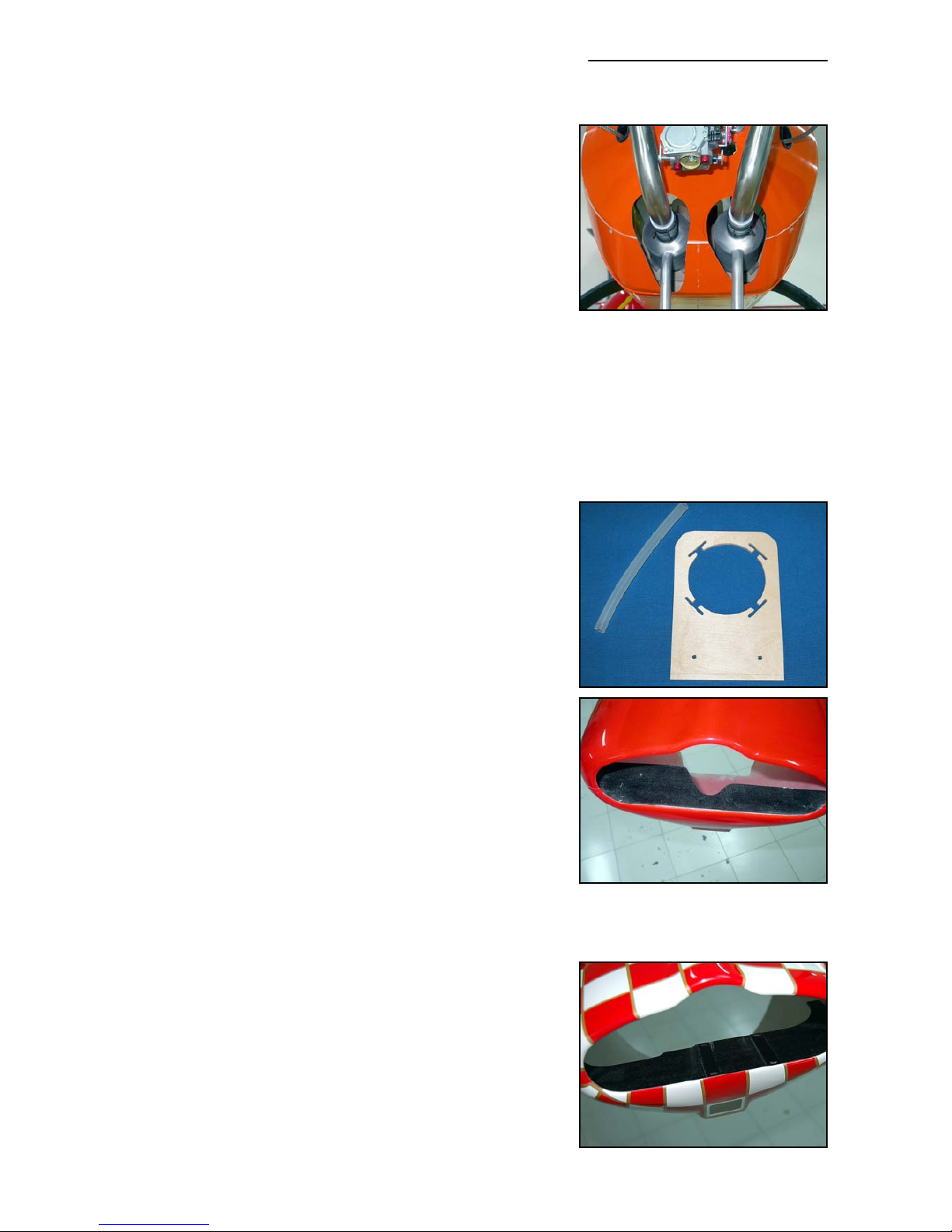
Canister and Header Installation
Shown here is the installation of a pair of MTW headers and
TD75k canisters, as included in the optional set available
from Composite-ARF. (see relevant webpage for details of
currently available accessories & options).
The assembled canisters and headers are inserted into the
fuselage through holes that you need to cut in the lower
surface of the motordome, as shown in the photo below, but
do not cut through the 25mm fibreglass joining tape in the
centre of the motordome.
Included in the kit are 2 cnc milled plywood mounts to suit
the TD75K canisters, or similar 70mm diameter cans (eg:
Zimmerman). Insert 20mm lengths of the (included) hard
silicone tube in the corner slots to make the isolation
mounts, in the same way as shown for tuned pipe mounts.
The plywood mounts can be screwed to the front of the
landing gear mount bulkhead with 2 of the Ø3.5 x 18mm
sheetmetal screws included in the hardware pack. No other
support is needed. Install 2 of the small sheetmetal screws
though each the teflon joiner into the canister entries and
headers to make sure that the cans cannot slide forwards
or backwards.
You can enlarge the semi-circular cutouts in the front of the
landing gear support if needed for larger diameter canisters, but ensure a minimum 6mm (1/4”) gap between the
bottom of the cans and the carbon landing gear, as mentioned above, to prevent heat damage.
Motor Cooling
It is imperative that your chosen motor not only receives
sufficient air to cool it through the opening in the front of the
cowl, but that the air is forced to go through the cooling fins
of the cylinder(s) - otherwise the air will just take the easiest route and exit the bottom of the cowl without doing any
cooling. In this case you will overheat, and damage, your
valuable motor.
Depending on your motor you will need to make some sort
of baffle to force the air through the cooling fins, and this
can be made from scrap 1.5mm plywood or 3mm balsa.
The full-size template at the end of this manual fits the
cowling, positioned about 10mm below the bottom of the
front cutout, and the back edge of the baffle can be adjusted slightly to suit your chosen motor.
Make the back edge of the baffle about 6mm (1/4”) clear of
the cooling fins of the cylinder(s) and the crankcase.
Glue the baffle plate into the cowl with epoxy. It looks
neater if you paint it matt black first, using heat-proof spray
Composite-ARF Extra 300SX (2.6m span)
28
(above) Cut large enough holes to
insert the cans through the motordome, taking note of the cooling
requirements mentioned here.
(below) Typical cnc milled plywood canister/tuned pipe mount
& hard silicone tubing included in
the kit to suit Ø 49mm pipes, and
both Ø 70mm & 80mm canisters.
(above/below) 2 views of sample
engine baffles; the top one for a
DA-100 and the bottom for a 3W.
Page 29
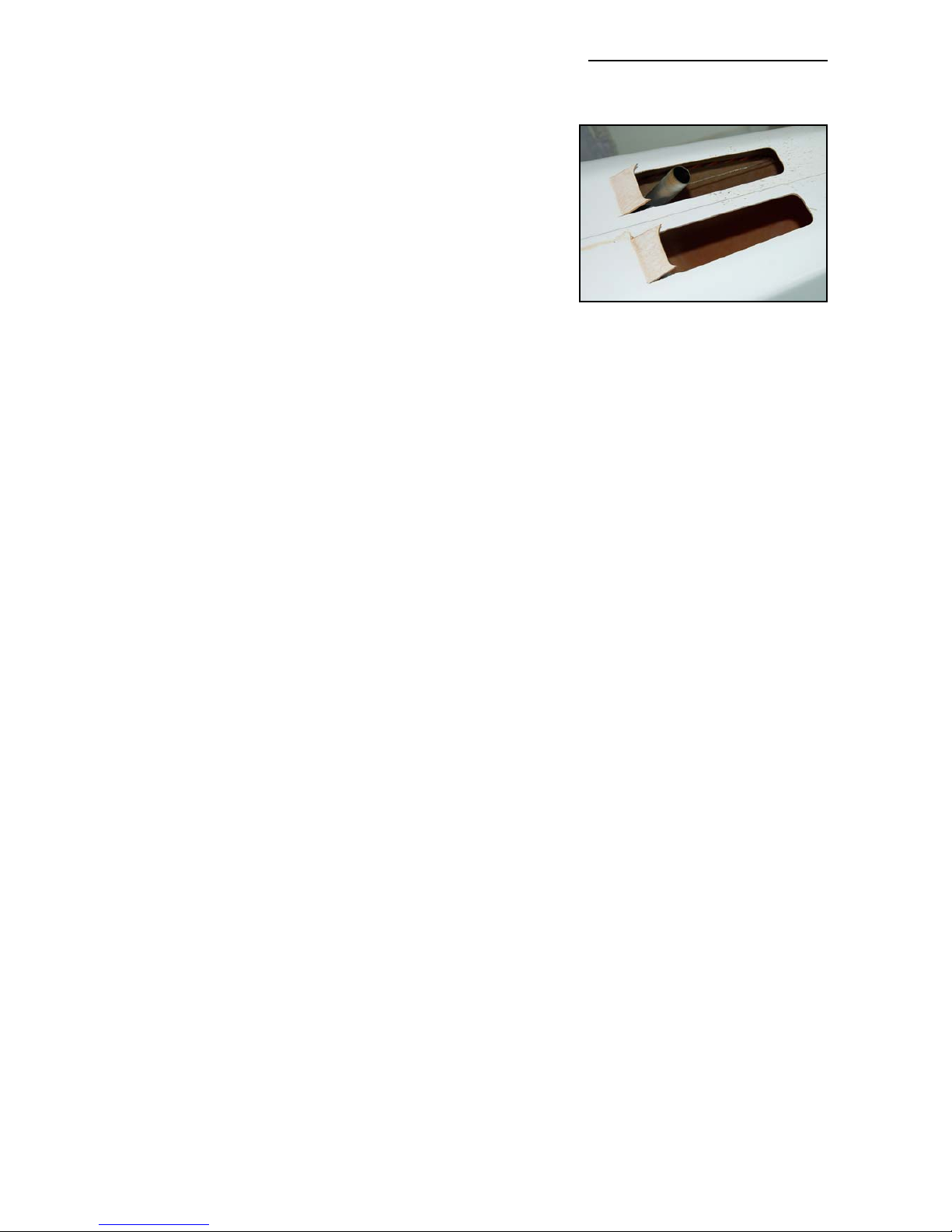
paint (as used for car manifolds/exhausts)
Exhaust Cooling
Whatever type of exhaust system you chose to fit, make
sure that the assembled headers and canisters, or pipe,
can be inserted from the front, through the motor-dome and make the hole(s) at least 18mm (3/4”) bigger than the
exhaust all around to ensure enough air enters the fuselage
to cool the exhaust system.
Of course, this warm air must also exit the fuselage - so you
also need to cut sufficient air exits in the bottom of the fuselage. As a general rule the total area of the air exits must be
at least double the inlet area. For example if the hole in the
motor dome for the tuned pipe is 75mm (3”) diameter (area = 4400mm
2
), then the total air exit
area should be about 8800mm
2
. This is equal to 2 slots of 50mm (2”) wide x 90mm (4”) long.
The balsa fin post also has cnc milled cut-outs in it, to help prevent a build-up of hot air inside
the fuselage. From our experience we have found that 2 slots, each of about 125mm x 45mm
wide provide excellent cooling for both the 3W and DA-100 set-ups shown here.
Cut the air exit slots in the bottom of the fuselage with a sharp knife, and sand the edges to
shape with 240 grit sandpaper - remembering to radius all the corners to help prevent tearing of
the composite sandwich skin. It is advisable to reinforce the edges of the cutouts with either a
few carbon rovings, or narrow strips of 3mm plywood. (see photo above)
It is also helpful to make small tabs at the front of the cooling slots to make sure that the warm
air is sucked out of the fuselage. These can easily be made by making 2 cuts in the skin, about
20mm long, bending the skin outwards about 30 degrees, and creasing the inner surface with
the back (blunt) edge of the knife blade. Hold in position, and apply a couple of drops of thin CA
to the sandwich from inside the fuselage to maintain the angle. (See photo P21)
Fuel Tank Base
The Fuel tank base is an integral part of the balsa/composite sheet assembly that also supports
the rudder servos. It is sized to fit a Dubro 960 cc tank (part #690) perfectly, but can be adjusted to suit your tank. Depending on the size of your fuel tank, glue a scrap balsa block at the front
of the tank base to stop the tank moving forwards. Secure the fuel tank to the tank base with 3
cable-ties as shown, through the milled slots.
Note: If you wish to fit the fuel tank base slightly off the centre of the fuselage - to give clearance
for tuned pipe of large single canister, for example - you can lengthen the slot in the vertical
balsa/composite bulkhead by up to 15mm to permit this. This slot is shown arrowed in photo P8.
Ensure that the semi-circular cutouts under the tank base are securely glued down to the fibreglass sleeve over the wing tube, with careful preparation, and using at least 30 minute epoxy and
micro-balloons mixture.
Don't forget to add the short lengths of 1” fibreglass tape (with laminating epoxy) to reinforce the
joint between the vertical balsa bulkhead behind the tank and the fuselage floor - and also
between the rudder servo plate and the fuselage sides. See photos P10, P23 and P24.
Composite-ARF Extra 300SX (2.6m span)
29
Radius the corners of all air exits,
and cut angled tabs at the front to
create some turbulence here and
make sure the air is sucked out.
Page 30
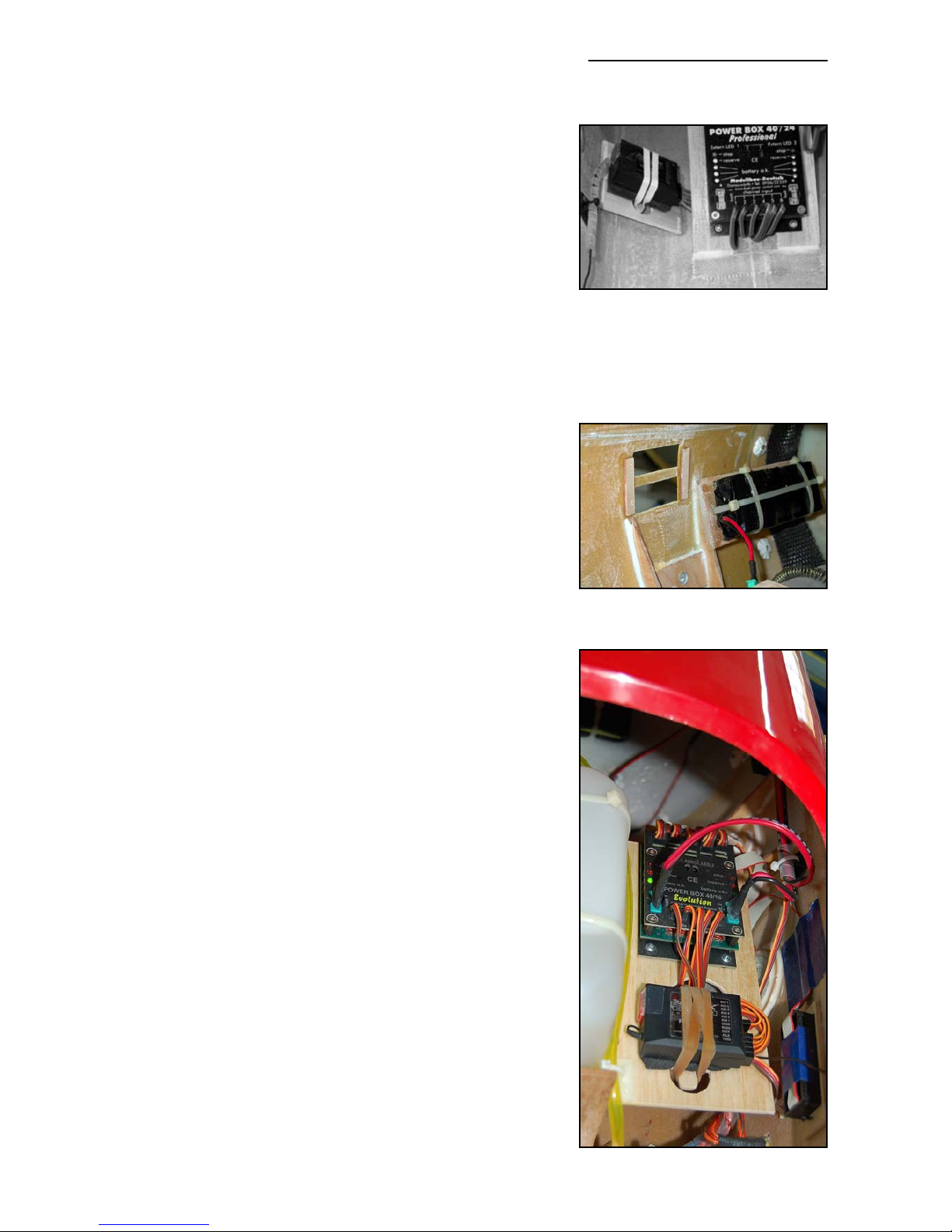
R/C & Gear Installation
Everyone has their own favourite methods and layouts
when fitting the R/C and gear and the installations shown
here, and on the full-colour photosheets, are just a guide,
but have worked perfectly in all of our planes flown by CARF factory staff, and many of our customers.
You have several choices of R/C system. You could keep it
simple, and use Dual receiver batteries and a Powerbox
sensor switch, which includes a regulator and batterybacker, or you could go for a ‘full-house’ set-up using a
high-quality servo powerbus system for the ultimate in safety and security. It’s your choice, but the dual Nicad and
powerbus installation does give extra ‘peace of mind’ and
protects your investment, and therefore this is what C-ARF
recommend and have shown here.
The PowerBox power control unit is designed especially for
large models and provides dual battery inputs with hi-amp
connectors, multiple outputs for 6 channels/24 servos (no
‘Y’ leads needed), automatic voltage regulation and stability, built-in servo amplifiers for those long servo cables, as
well as dual visual LED battery displays. It comes complete
with hi-current connectors and is fitted with anti-suppression chokes on all channels. The full ‘PowerBox’ range is
available from C-ARF as an option. Please visit our website
for more details.
Ignition Batteries
Both examples shown here used a 2400 (sub-C sized cells)
ignition Nicad. The 4-cell pack for the DA-100 was secured
inside the front of the motor dome with cable-ties, and the
5-cell pack for the 3W motor was fixed to the underside of
the motor baffle plate to move it as far forward as possible
- for correct Centre of Gravity. Small plywood strips were
glued to the balsa baffle to spread the load of the cable ties
(photo page 28). The battery cables plug into a multiplex
connector that is glued into the bottom of the motor dome,
for ease of removing the cowling. (photo P16)
Make sure that all batteries, and other heavy items, are
very securely fixed in the plane - remember how much they
will effectively weigh when subjected to 4 or 5 G’s!
Receiver Batteries
In the DA-100 powered example we used two 5-cell 2400
Nicads (sub-C size) for the Powerbox, one installed in the
motor dome and the other on the fuselage floor just behind
the rudder servo plate. Both were cable-tied to a 3mm plywood plate, glued in with 30 minute epoxy and reinforced
with small pieces of the 1” wide fibreglass tape.
Composite-ARF Extra 300SX (2.6m span)
30
(below) Powerbox, Receiver and
switch location in the Extra 300SX.
(above) The Powerbox can be
screwed to the plate behind the
rudder servos if using a DA-100.
(below) NiCad packs can be fitted
to plywood plates on a thin rubber
sheet, and secured with cable-ties.
Page 31
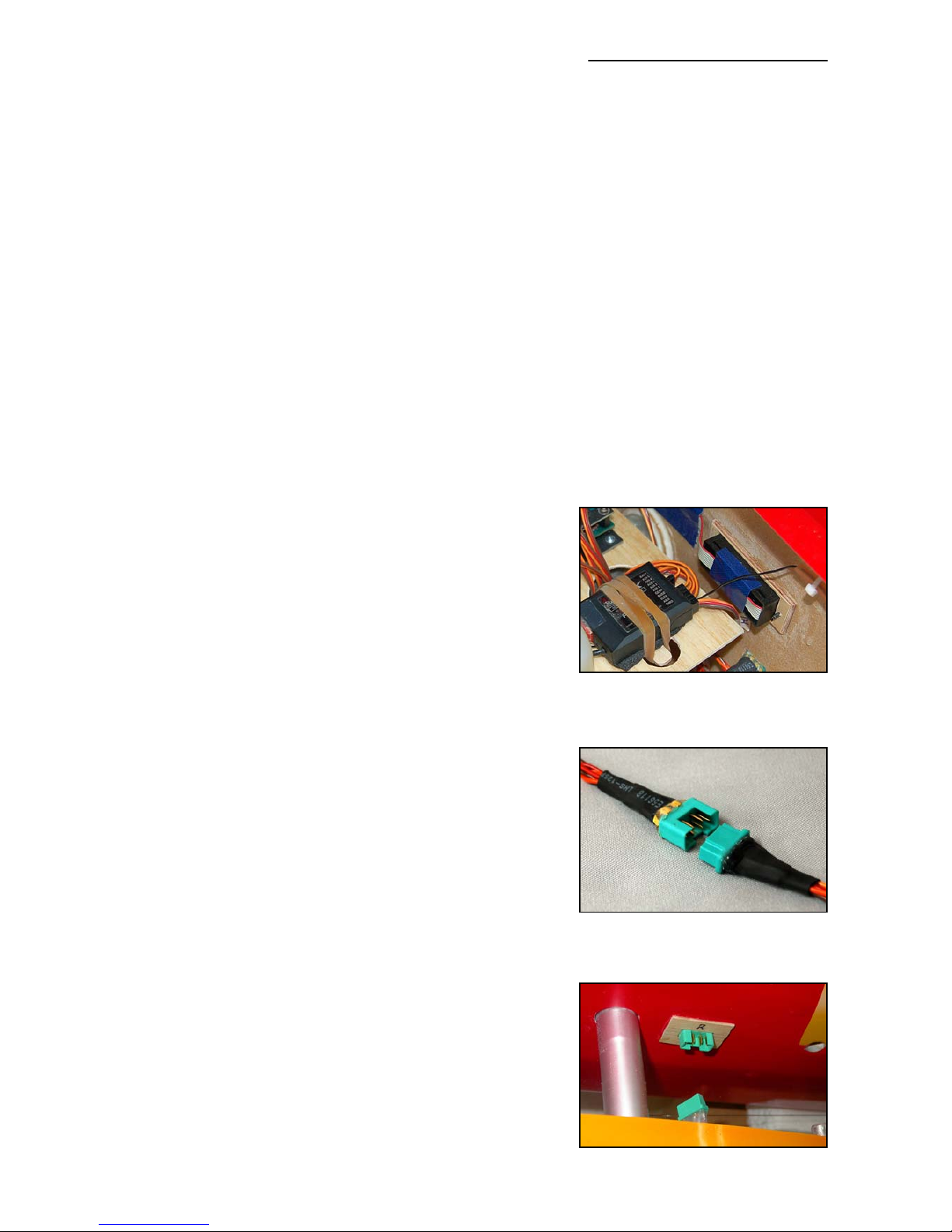
To save weight in the 3W powered plane, we chose two 5-cell (AA-sized) 1400 mAH packs - and
these were both fixed inside the front of the motor dome. No additional lead was required to
achieve the correct Centre of Gravity. All battery packs should be wrapped in foam to isolate the
soldered connections from vibration as much as possible.
Receiver
We strongly advise that you position the receiver as far away from the high-voltage ignition unit
as possible - at least 200mm (8”) for the minimum interference risk. In the DA-100 version it was
secured to the side of the fuselage, close to the angled plate behind the rudder servo mount
which was used to locate the Powerbox.
In the 3W version, to get everything as far forward as possible, we positioned the Powerbox
Evolution and the Receiver on a balsa-composite plate, glued to the top of the wing tube sleeve
- on the right side of the tank base.
Please mount the sensitive Receiver on a rubber or foam sheet, at least 3mm thick, to isolate it
from vibrations. You can easily secure the Rx by gluing a plywood stick across 2 large holes in
the mounting plate - using 2 rubber bands around the Rx case. (see photo below)
RX Antenna
In both cases the Rx antenna was routed to the side of the
fuselage, then backwards along the fuselage side and out
of the top of the fuselage immediately behind the canopy and taped to the top of the fuselage. Secure it in short
lengths of silicone tube to make sure it cannot be cut
through by any sharp edges. Keep it as far away as possible from the cables for the elevator servos and the closedloop rudder wires.
Switches
Often regarded as the ‘weakest-link’ in an R/C system, it is
very important to use quality switches for both
Receiver/Powerbox and motor ignition, and we only use
high quality switches from Power box. The electronic switch
included with the Powerbox Evolution is a ‘Fail-ON’ type, as
is the Powerbox ‘Sensor’ switch. We use the analog 20
Amp power-switches, also from powerbox, for the ignition
system.
If fitting the switches into the outside surface of the fuselage, as shown, please reinforce the area inside with a
small patch of 3mm thick plywood to reduce vibration transmissions to the switches. It only adds a few grams. The
Powerbox switches come with paper templates, making it
easy to cut the slots in the fuselage accurately.
Servo Extension leads etc.
Please make sure that you use good quality twisted-cable
extension leads, of heavy gauge wire with gold-contact
connectors, to all the servos. Certainly we recommend that
all servo leads and extensions longer than about 30cms
(12”) are fitted with ceramic chokes (ferrite rings) to prevent
RF noise, at the receiver end - normally within 100mm (4”)
Composite-ARF Extra 300SX (2.6m span)
31
6-pin MPX connectors are used for
extension leads, with one half
mounted in the fuselage sides.
(above) 3mm plywood reinforcing
plate glued inside the cutouts in
the fuselage sides for switches.
Page 32
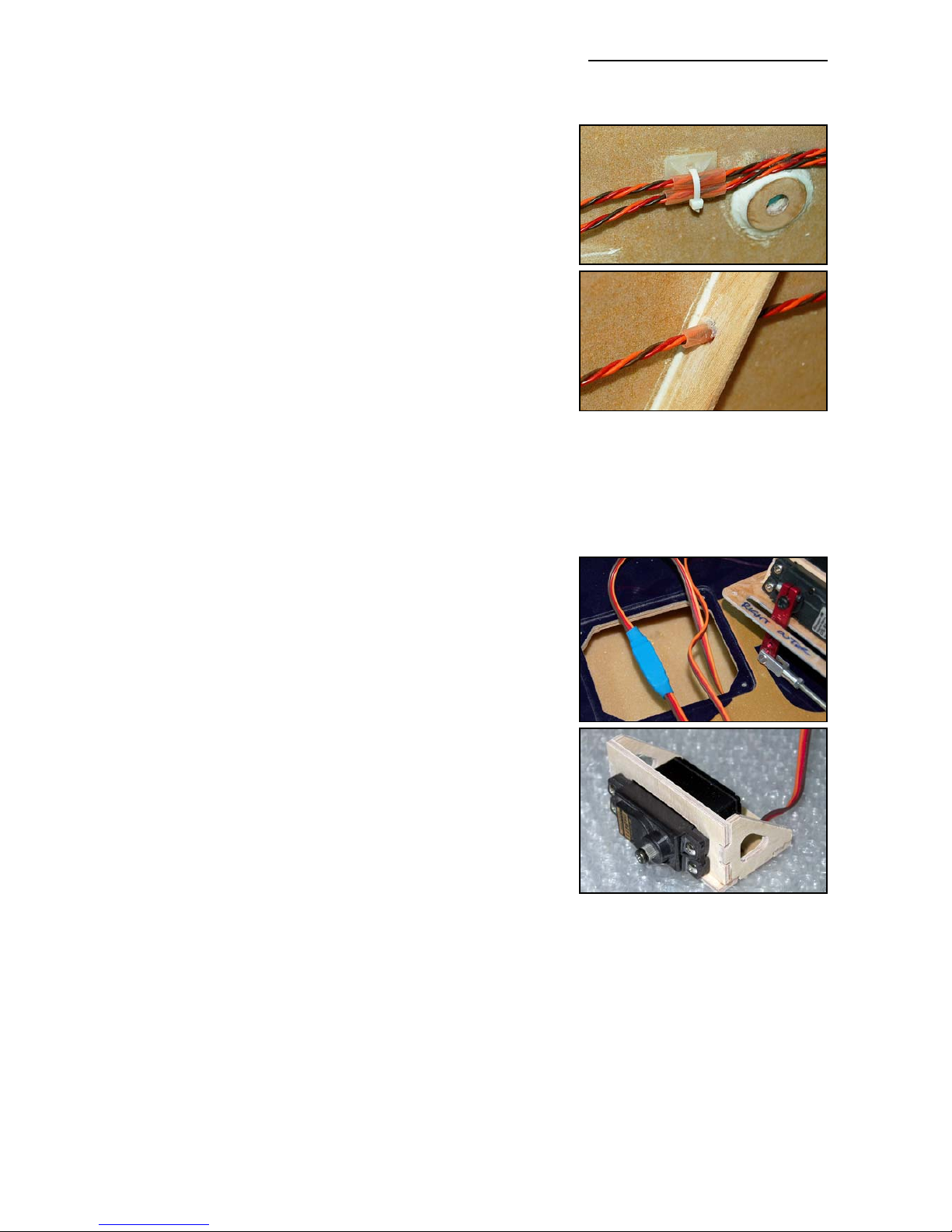
of the receiver. Of course, if you are using a ‘Powerbox’ this
unit is already fitted with all the ceramic chokes. Also no ‘Y’
leads are needed, as the powerbox provides multiple inputs
for each channel.
At C-ARF we hard-wire all our servos with twisted cable
leads of the exact length required and Multiplex 6-pin connectors (see photos on page 31). For the 2 aileron servos
you can use 1 pin for each wire, and for the elevators you
can gently squeeze pairs of adjacent pins together and use
a pair of pins for each cable. We glue the female connectors into small plywood plates in the sides of the fuselage
for connecting the stabs and ailerons when assembling the
plane. Making up the proper extension cables and connectors is only a little work, if you are proficient with a small soldering-iron, and makes assembly of the model at the airfield very quick and easy! Once all wires are soldered to the
gold-plated pins, fit a short length of heat-shrink tube over
each one. Finally protect all the connections from vibrations
etc with a nice blob of glue from a hot-glue gun. Job done.
Make sure that any plug/socket servo cable connections
that cannot be easily seen and regularly checked, for
example the servo connections in the wings, are secured
together with tape - or a short length of heatshrink tubing
as shown here. Also tape down any loose cables that could
get trapped or caught in linkages.
Throttle servo
You can install the throttle servo anywhere you want, using
the milled plywood mount that we supply (photo right). In
the 300SX we securely glued it to the underside of the top
of the fuselage, with epoxy/milled fibre mixture, just in front
of the fuel tank.
In a plane with a DA-100 and dual canisters, you will be
able to glue the mount to the side of the fuel tank base and
use a balsa or carbon-tube pushrod through the firewall to
the carburettor. We advise you not to mount it directly on
the back of the firewall, due to higher vibration levels which
can quickly ‘kill’ the servo. Note that all DA motors need
quite a lot of servo throw to get the full throttle range, so
make sure you can fit a long output arm on the servo.
M3 all-thread, steel clevises and locknuts are included in the hardware pack to make up your
throttle pushrods.
Make up a wire lever so that you can operate the ‘Choke’ for starting thru’ the cut-out in the front
of the cowling. In the 3W installation this wire is very long, because of the rear-mounted carb, so
the wire pushrod passes through a length of silicone tube in the bottom of the carbon plate to
support and isolate it. (see photo P14)
Composite-ARF Extra 300SX (2.6m span)
32
(above) Throttle servo mount
assembled from milled plywood.
(above) Protect all wires and tubes
where they pass thru’ bulkheads,
or near sharp composite parts,
with a short length of silicone tube,
and fix firmly in position.
(below) Secure all hidden servo
plugs/sockets with heatshrink.
Page 33
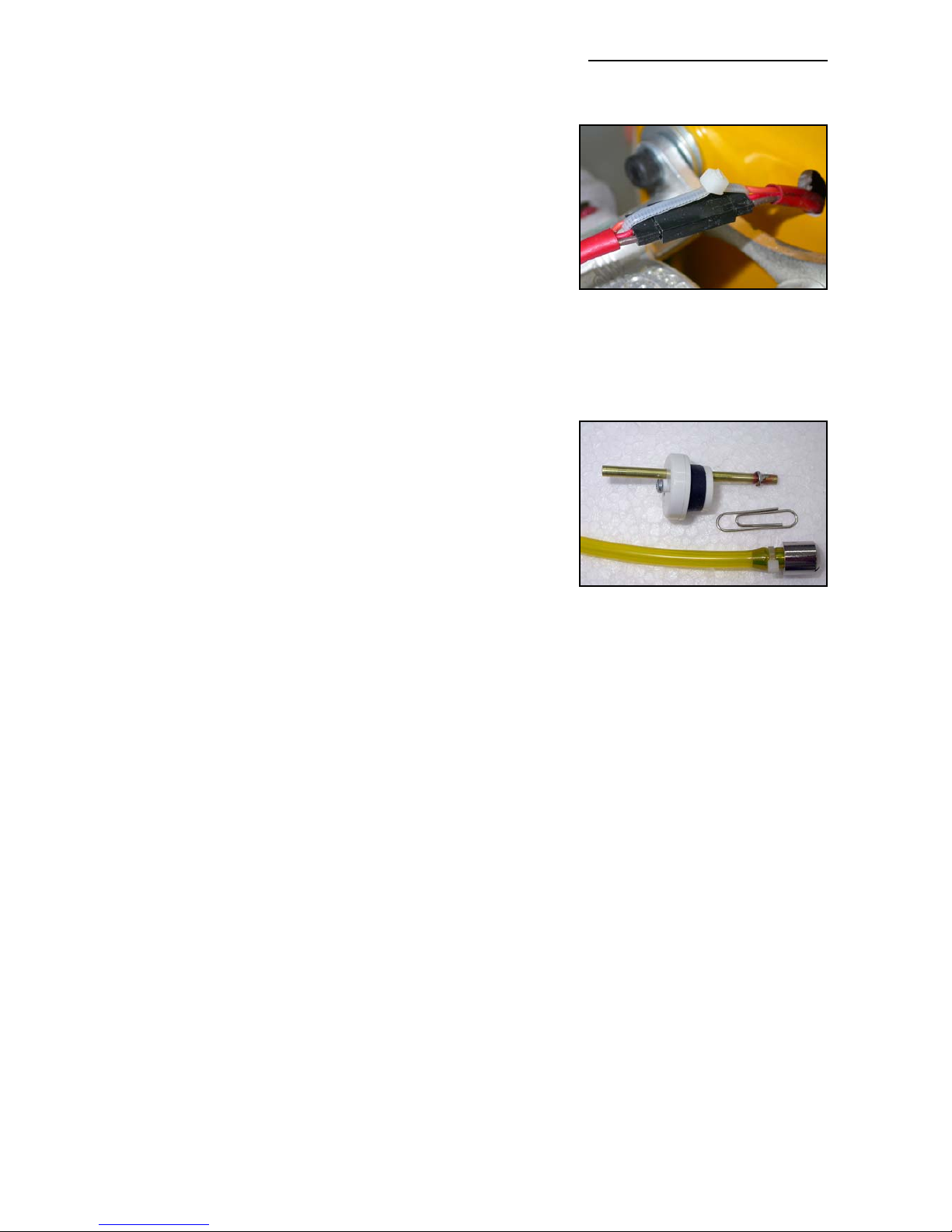
Motor Ignition System
The ignition unit is normally fixed to the motordome, as
close to the engine as possible - because of the length of
the HT leads that connect to the spark plug(s). Mount it on
a foam pad and secure with cable-ties, or use sheetmetal
screws into small plywood pads with rubber grommets for
vibration isolation. Don’t forget that the ignition unit also
gets warm during use, so it is wise to put it in a location
where there is some cooling airflow.
Use a very small cable tie, ‘safety clip’, or a length of heatshrink tubing to securely connect the plug and socket from
the motor pick-up to the ignition unit.
Fuel Tank
The fuel tank is held to the tank base with 3 large cable-ties
(photo on page 29 and P23). Drill a hole in the motor firewall if necessary for the fuel feed tube from the tank to the
carburettor, and protect it where it passes through the hole
using a rubber grommet or similar. Fix the tubing securely
to the underside of the top of the motordome with a couple
of cable-ties or equivalent, to make sure that it cannot come
in contact with the headers or hot exhausts.
Fit the correct stopper to the fuel tank for the fuel type used.
(If using Dubro tank the gasoline stopper has a small ‘O’ moulded in the top of it). We use the
excellent ‘Tygon’ brand of fuel tubing for all our aerobatic models. It is totally gasoline and
kerosene-proof, and does not go hard and crack with age. Secure the feed tube inside the tank
to the clunk with a small cable tie. If the tube is even a little loose on the brass tubes though the
stopper, you can be sure it will come off at just the wrong moment and your engine will quit !
Therefore please solder some small rings onto both ends of the brass tubing (easily made from
the soft wire of a paperclip wrapped around a small screwdriver, or short lengths of brass tube)
and also secure with a fuel-line clamp or cable-tie. Don’t miss this small detail - it could cost you
your plane !
We use the normal 3 tube plumbing system, one from the clunk to feed the motor, one out of the
bottom of the plane (vent/overflow - leave open) and one at the top for filling (close for flight).
If you want to fit a smoke system the smoke tank can be fitted alongside the fuel tank but you
will need to make an extra platform for it. Follow the manufacturers instructions for fitting the
smoke system.
Final Check
Now check that you have fixed all components securely. Keep in mind that all the components
inside the aircraft are loaded with the same G’s as the wing and the wing spar during aerobatic
maneouvers. Check engine, cowling, wing and stab mounts carefully again.
- Are all extension leads, cables & fuel tubes securely fixed to the side of the fuselage
and cannot come loose when subjected to high ‘G’ forces during flight.
Composite-ARF Extra 300SX (2.6m span)
33
(below) Secure the connectors
between the motor & ignition unit.
(below) Fit barbs to all brass tubes
and fuel connections for safety.
Easily made from a paper-clip, soldered onto the brass tubes.
Page 34
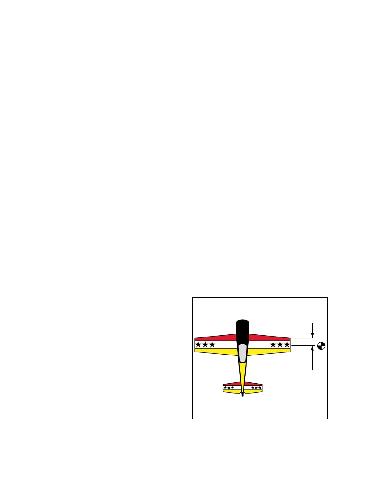
- Are all tubes and wires protected from chafing where they pass thru’ the holes in fibre
glass parts or bulkheads with rubber grommets, or short lengths of split silicone tubing?
- Especially if you have installed the internal mini-pipe set-up, you also must make sure
that no fuel tubing or wires can come into contact the exhausts. Use the plastic spiralwrap to tidy up groups of cables and make sure that they cannot move around in the
plane under high ’G’ manoeuvres by fixing them to the sides with small cable ties. If using
the easily-available cable-tie plastic fixing plates, please do not trust the double-sided
tape that they usually have on them which can fail under vibrations. Peel it off, rough up
the back face with coarse sandpaper and glue to the fuselage sides with 30min. epoxy.
-
Did you fit small Tygon or silicone tube pieces over all the clevises?
- Did you tighten the M3 locknuts against all the clevises to make sure they cannot turn?
- Are the swages crimped up nice and tight on the rudder cables?
- For added security add one small drop of loctite/thread locking compound on all the bolts
that hold the servo arms to the servos, especially important with digital types.
Then you can go on set up all the linkages, control throws and R/C system as described below.
Setting Up Your Aircraft
Centre of Gravity:
Set the Centre of Gravity to 90 - 100mm (3.3
- 4”) from the leading edge at the wingtip for
the 1st flights. Hold it with a helper at both
wing tips in this position and make sure the
plane balances horizontally. This is the ‘pattern’ CG position.
After you are confident with the plane, you
can move it backwards by up to 20mm (7/8”)
maximum, but this is definitely a ‘3D Freestyle’ CG setting and should not be used
for the first flights. With this rearward CG you
will need to use the high rate control throws
shown below.
Don’t forget to balance the plane laterally,
holding the spinner central bolt and a fingertip
under the rudder and, if necessary, add a
small weight to the light wing tip to make it
track correctly.
Composite-ARF Extra 300SX (2.6m span)
34
C of G range:
90 -100 mm
from Leading Edge at Wing Tip.
CENTRE of GRAVITY
90-100mm
Page 35
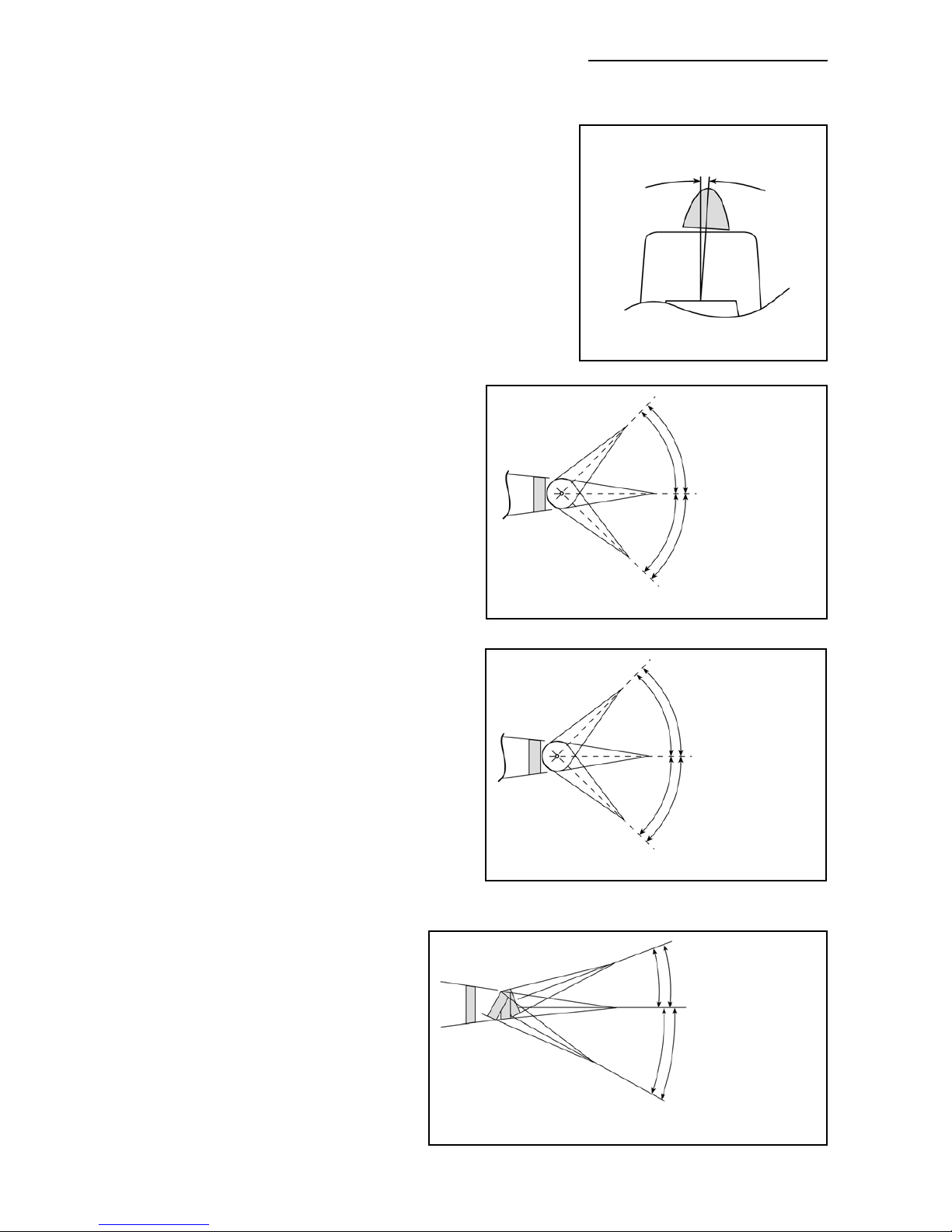
Engine Thrustline:
Already given in the instructions, down thrust should initially be set at 0° degrees and right thrust 2.5 - 3 degrees,
depending on the prop used. We recommend a 27 x 10 on
a 75 - 80cc motor, and a 28 x10 carbon prop for any 100cc
engine. It is a very quiet and powerful solution. They are
normally CNC-designed, so the prop is balanced perfectly
statically, dynamically and aerodynamically, which keeps
the vibration down to a minimum.
Control Throws:
All measurements are at the root/trailing edge position.
All controls should be set with a dual rate
switch.
Elevator
On high rate the elevator should really be at
maximum, up to 50 degrees both sides
(approx. 100mm), but in this case with 50%
exponential. Low rate should be no more than
50mm (2") both sides. This is the perfect
throw for nice and crisp snaps. If you like you
can add about 20% exponential to the low rate
setting as well.
Rudder
Set the high rate to maximum throw (about
150mm) both sides, and at low rate reduced
to about 100mm. The Extra needs quite a lot
of rudder for nice stall turns, so you should at
least add 25% exponential for smooth tracking corrections. At the same time you should
remember that the Extra rudder is very sensitive, and the plane starts shaking at high
speed if the rudder linkage is not really rock
solid. So check your linkages and closed-loop
cables again and make sure that there is NO
slop at all ! On the other hand these characteristics are also the reason for best rudder
sensitivity at the slowest 3D-speeds.
Ailerons
Aileron throw for high rate is 65mm up
and down (measured at root). Use at
least 30% exponential at high rate.
For low rate you should decrease the
throw to the TOP to 45mm, to the
BOTTOM to 50mm. Yes, you’re right
- this is a reversed differential due to
the hinge line being in the top skin
instead of on the centre line. You will
have to finalise this differential figure
Composite-ARF Extra 300SX (2.6m span)
35
2.5 - 3° depending on propeller
SIDETHRUST
ELEVATOR THROWS
high rate: 100mm (max.)
low rate: 50mm
low rate: 50mm
high rate: 100mm (max.)
RUDDER THROWS
high rate: 150mm (max.)
low rate: 100mm
low rate: 100mm
high rate: 150mm (max.)
AILERON THROWS
low rate: 50mm down
high rate: 65mm (max.)
high rate: 65mm up (max.)
low rate: 45mm up
Page 36

during flight, as mentioned earlier in this instruction book. At high rate, for 3D maneouvers, this
doesn’t effect the rolling too much, so you can maximize the throws to whatever is mechanically possible, even more up than down if you wish. You may need to lengthen the slots in the servo
hatches by 2mm or so at the front to obtain these high rate throws.
General
Your Extra has very large control surfaces. This makes it very sensitive and reactive. It is always
possible that these huge control surfaces can flutter at high speeds if the assembly, servo installation and linkages are not made perfectly, and if a servo gear or output disc/arm strips the flutter will not stop until the plane hits the ground….
So please do yourself a favour, and make sure that you only use the best servos available, and
take the utmost care making your linkages. Check every linkage for slop, and rather reduce the
maximum throw than risking a high speed flutter due to sloppy servo gear or linkages. To prevent this for sure, we recommend reduced control travels (reduced by using short servo arms,
not by using electronic settings). Using 2 servos per control surface as described in this manual will never overload or damage high quality servos, even if the maximum travel of each servo
is slightly off. The aileron control surfaces have enough torsion flexibility so that damage to the
servos should not occur.
The Composite-ARF aerobatic models are known for very good and crisp ‘snapping’, and we
think that this is also true for the 2.6m 300SX version. It’s like an explosion ... and it still stops
immediately that the sticks are released. Be aware of this fact when you try it for the first time.
The trick for nice crisp ‘snaps’ is to stall the plane with a quick hit of ‘up’ elevator, and then
release the elevator to zero, while you give full rudder and aileron together. But of course, you
know this needs some practice to make it perfect every time !
Perfect knife edge tracking is achieved by mixing in slight up elevator, and opposite aileron to
the rudder movement. From our experience as little as 6 - 7% ‘up’ elevator and 2 - 3% of opposite aileron are needed.
Now your Extra seems to be ready for the first flight. Always keep in mind, that you have a rock
solid, but still sensitive, contest tool in front of you, which, if used as it is designed will give you
many hours of pleasant flights. The performance of this aircraft is unlimited, and if maintained
regularly and carefully, you will enjoy it’s performance for many, many hours. With this aircraft
you have the potential to move up to the unlimited "cracks". It’s up to you now - you can’t blame
it on the aircraft anymore….!
We hope that you enjoyed building your Extra 300SX. Please let us know if you think that any
hardware is missing or inadequate. We tried to make this airplane as complete as possible. With
good feedback from customers you will help us to continue making good things even better. We
appreciate your comments very much.
Email: [email protected]
Have Fun!
Your Composite-ARF Team
Composite-ARF Extra 300SX (2.6m span)
36
Mike C Mike C (10 Jan 2007) Mac
Page 37

Appendix:
Extra 300SX, 2.6m Kit (version 1.0)
Kit Contents
Quantity Description
1 Fuselage
1 Wing, right (with 2 servo hatches taped in place)
1 Wing, left (with 2 servo hatches taped in place)
1 Stab, right
1 Stab, left
1 Elevator, right
1 Elevator, left
1 Rudder
1 Cowling
1 Protection bag set (wing, stab and rudder)
1 Canopy frame
1 Wheel pant, right
1 Wheel pant, left
1 Cuff for LG (right)
1 Cuff for LG (left)
1 Landing gear, carbon, right
1 Landing gear, carbon, left
1 Wing tube aluminum Ø 40mm x 1040mm.
1 Stab tube aluminium Ø 20mm x 300mm.
1 Clear canopy
2 Elevator hinge aluminum tube, Ø 4mm x 475mm. (packed in elevators)
1 Rudder hinge wire, Ø 2mm x 500mm (packed in rudder)
1 Milled wood/phenolic parts bag
1 Hardware bag
1 Instruction Manual (English)
Hardware List
Fuselage Pack
Quantity Description
4 Allen Bolt M6 x 40mm (engine mounting)
8 Washers, M6, large (engine mounting)
4 T-nut, M6 (engine mounting)
9 Allen bolt, M3 x 12 (cowling)
9 Washer, M3 (cowling)
9 T-nut, M3 (cowling)
4 Allen bolt, M6 x 20mm (landing gear fixing)
4 Washer, M6 (landing gear fixing)
2 Allen bolt, M6 x70mm (wheel axle)
4 Wheel collar, 6mm I.D, no set-screws. (wheelpants)
6 Washer, M6 (wheelpants)
2 Nut, M6 (wheelpants)
2 Stop-Nut, M6 (wheelpants)
2 Allen bolt, M3 x 16mm (wheelpants)
2 T-nut, M3 (wheelpants)
2 Washer, M3 (wheelpants)
2 Silicone tube, Ø10 x 150mm (muffler mounts)
4 Allen bolt, M4 x 8mm (canopy frame fixing)
4 Plastic Nut, M6 (wing mounting)
Composite-ARF Extra 300SX (2.6m span)
37
Page 38

2 Nut, M3 (throttle linkage)
1 Clevise steel, M3 (throttle linkage)
1 All thread, M3 x 125mm (throttle linkage)
1 Ball-link, M3 (throttle linkage)
1 Stop Nut, M3 (throttle linkage)
1 Fibreglass band, 25mm x 300mm (tank base fixing etc)
4 Sheetmetal screws, Ø3.5 x 18mm (exhaust mount fixing)
Wing Pack (2 sets)
Quantity Description
8 Sheetmetal screws, Ø2.9 x 10mm (servo hatch fixing)
8 Sheetmetal screws, Ø2.9 x 13mm (aileron servo fixing)
4 Bolts, M2 x 15mm (secure phenolic arms to servo discs)
4 Nuts, M2 (secure phenolic arms to servo discs)
2 All-thread, M3 x 45mm (linkages)
4 Clevise, steel, M3 (linkages)
4 Nut, M3 (linkages)
Stab Pack (2 sets)
Quantity Description
4 Sheetmetal screws, Ø2.9 x 13mm (elevator servo fixing)
2 Bolts, M2 x 15mm (secure phenolic arms to servo discs)
2 Nuts, M2 (secure phenolic arms to servo discs)
1 Allen bolt, M3 x 20mm (stab tube security)
1 T-nut, M3 (stab tube security)
1 All-thread, M3 x 45 (linkages)
2 Clevise, steel, M3 (linkages)
2 Nut, M3 (linkages)
Rudder Pack
Quantity Description
8 Sheetmetal screws Ø2.9 x 13mm (rudder servo fixing)
4 Allen bolts M3 x 16 mm (ball-links to phenolic discs)
4 Bolts, M2 x 15mm (secure phenolic arms to servo discs)
4 Nuts, M2 (secure phenolic arms to servo discs)
4 Stop Nuts, M3 (ball-links to phenolic discs)
2 All thread, M3 x 55mm (ball-link to ball-link)
4 Ball-links, M3 (servo linkages)
1 Steel cable, 0.8mm x 2800mm (rudder linkage)
4 Crimping tubes, I.D. 2.6mm (rudder linkage)
2 Threaded ends for cables, M3 (rudder linkage)
2 Nuts, M3 (for threaded ends)
2 Clevise, steel, M3 (rudder connection)
‘Spare’ hardware pack
* This bag contains a few extra items that might be useful in the event of future maintenance or repair.
2 Ball-links, M3
2 Phenolic control surface horns
2 All-thread, M3 x 150mm
2 Allen-bolt M3 x 20mm
2 Stop Nut, M3
1 Allen Bolt M6 x 70mm
2 Allen bolt, M4 x 12mm
2 T-nut, M4
2 T-nut, M3
Composite-ARF Extra 300SX (2.6m span)
38
Page 39
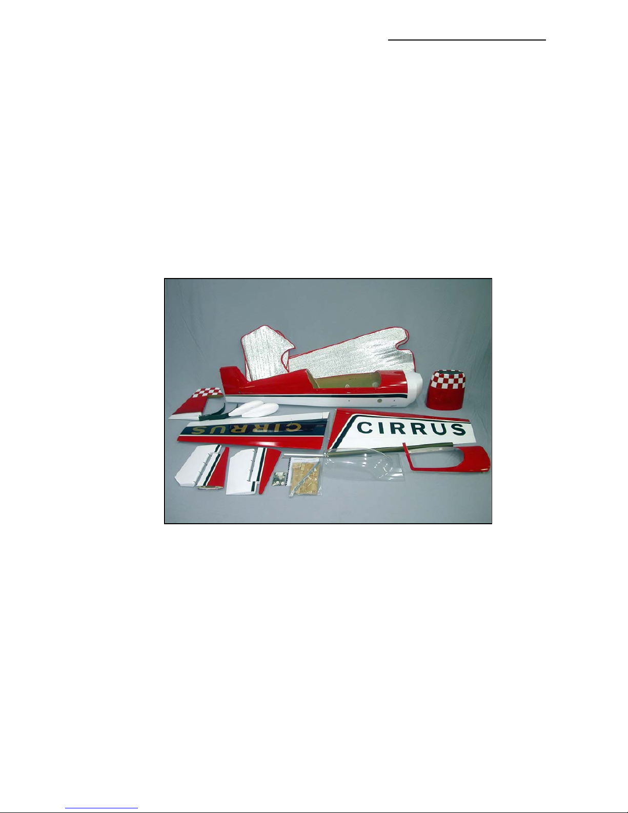
Available Accessories:
Tail gear setup with 50mm Ø wheel, size ’L’. (product #801000)
Spinner, Ø 120mm, alu. backplate & carbon spinner (product #810100 - 810103)
Desert Aircraft DA-100 motor (product #950000)
Canister set for DA-100 (product # 910100)
PowerBox 40/24, dual NiCad crossover unit. (product #960200)
PowerSwitch, pair, 20A, for dual NiCads (product #960300)
* Please check our website : www.composite-arf.com, for current availability of options and accessories.
Composite-ARF Extra 300SX (2.6m span)
39
(above) Contents of the complete kit
Page 40
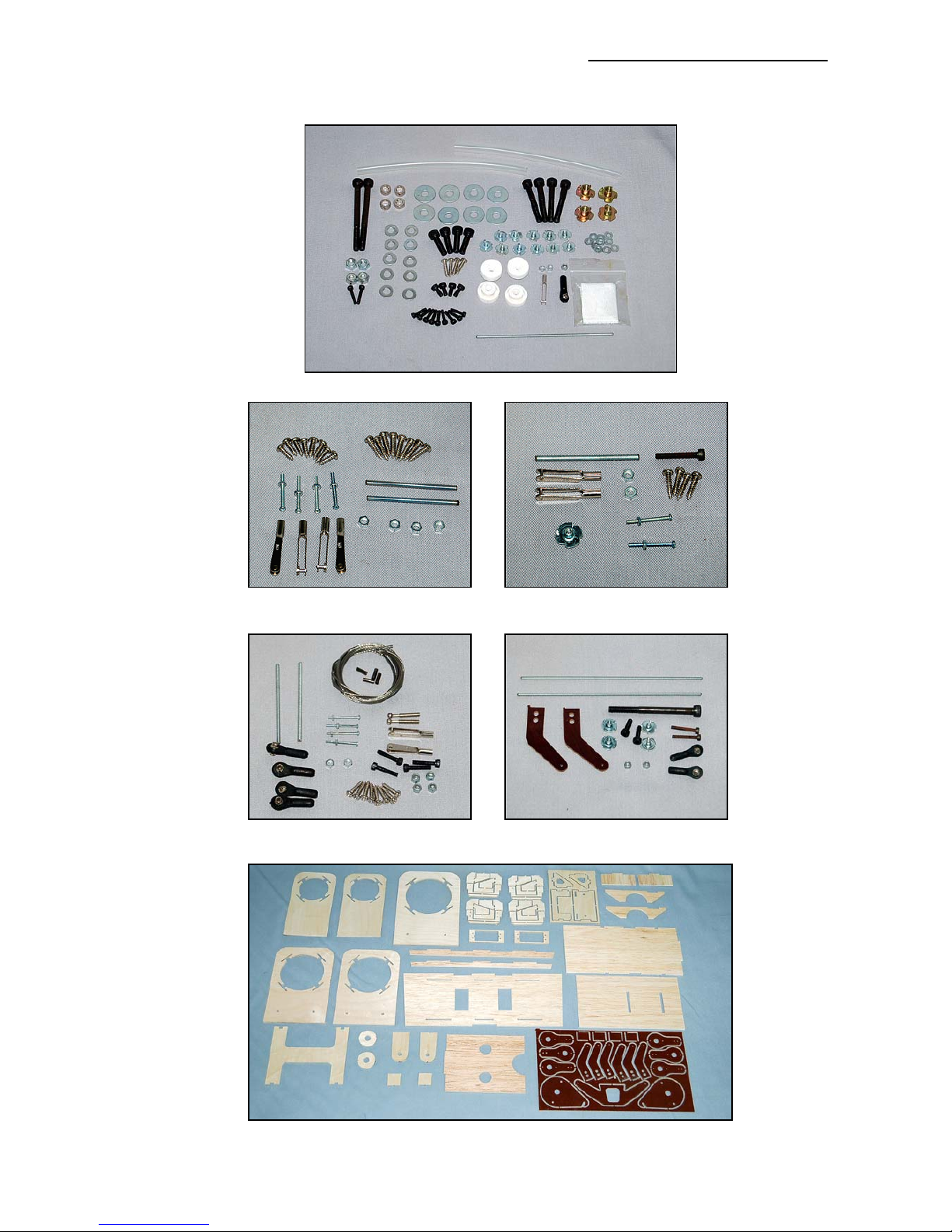
Composite-ARF Extra 300SX (2.6m span)
40
Contents of Wing Hardware
pack (2 sets)
Contents of Stab Hardware
pack (2 sets)
(above) Contents of Rudder
Hardware pack
(above) Contents of Spare
Hardware pack
(above) Contents of Milled wood and Phenolic pack
(above) Contents of Fuselage hardware pack
Page 41
Composite-ARF Extra 300SX (2.6m span)
41
308 mm
Full-sized Baffle template for Extra 300SX, 2.6m span.
Adjust back edge of baffle
so that it is 6mm (1/4”) from
cooling fins and crankcase
of your motor. (This line
suits 3W 80cc Xi motor)
Page 42
 Loading...