

Page 1

COMPOSE
AGFA
PCI Interface Card
Installation Manual
for
Harlequin Level 2 Intel Windows NT RIP
v1.01 1Jul96
Compose System Limited
1705 Westlands Center,
20 Westlands Road,
Quarry Bay, Hong Kong
Tel: (852) 2811-4228
Fax: (852) 2811-2263
E-mail: [email protected]
Web: http://www.compose-sys.com
Page 2

INSTALLATION INSTRUCTIONS COMPOSE AGFA PCI I/F CARD
Table of contents
1. Features 1
2. Installation Procedures 1
3. Agfa PCI Card Configuration 10
1. Agfa PCI Card Versions 12
2. Agfa Imagesetter Information 13
3. Agfa Driver Configuration File 14
4. EDGE TO EDGE FEATURE (ETOE) 15
5. Agfa Driver Files 15
Appendix
Page 3

• The Compose Agfa PCI Interface Card is designed for Harlequin level 2 RIPs running
on the PC platform.This card allows a PC-PCI system to output data to all Agfa imagesetters. (There are 3 different versions of Agfa Interface Card. The AccuSet/ProSet
card can output to all Agfa imagesetters except the SelectSet and Avantra. The SelectSet
card can output to all Agfa imagesetters except the Avantra. The Avantra card can output to all Agfa imagesetters.)
• Interface cards can be daisy-chained via the optional Slave Buffer Boards to connect
multiple RIPs to an imagesetter.
• For PCI PCs whose BIOS does not allow the user to specify which PCI slot uses which
interrupt level, an ISA paddle-card and cable is provided to allow the PCI card to
access interrupts using the ISA bus.
Warning:- Please READ ALL of this Manual before proceeding with the following.
1. Install the Express Windows NT (Intel) RIP according to the RIP installation manual.
2. Before installing an interface card, check your machine’s warranty and follow any
instructions it contains to ensure that you do not invalidate it.
2. INSTALLATION PROCEDURES
1. FEATURES
Page 1
INSTALLATION INSTRUCTIONS COMPOSE AGFA PCI I/F CARD
Page 4
Page 2
INSTALLATION INSTRUCTIONS COMPOSE AGFA PCI I/F CARD
3. Installation of the Agfa Driver
i. Insert the Driver Installation Disk into Drive A:.
ii. Choose RUN in the File menu in the Windows NT Program Manager.
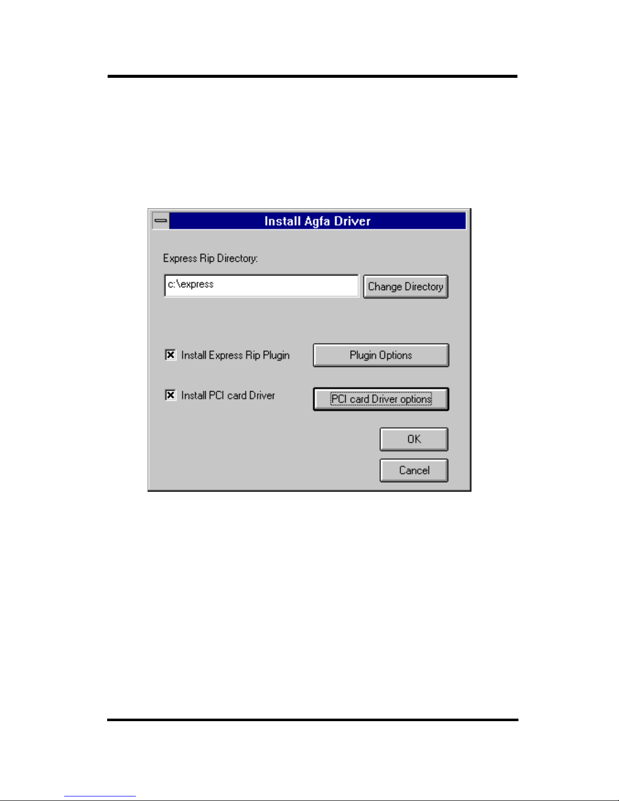
iii. Type ‘A:\INSTALL’ and hit ‘enter’ to continue. You will see the Install Agfa
Driver Window:
iv. In the
Express RIP Directory field, choose the directory where you installed the
Express RIP. Click on Change Directory to select another directory. For example, for
the Compose Express RIP which be default is installed in the EXPRESS directory,
you should type in C:\EXPRESS or select the directory by clicking the Change
Directory button.
Page 5
Page 3
INSTALLATION INSTRUCTIONS COMPOSE AGFA PCI I/F CARD
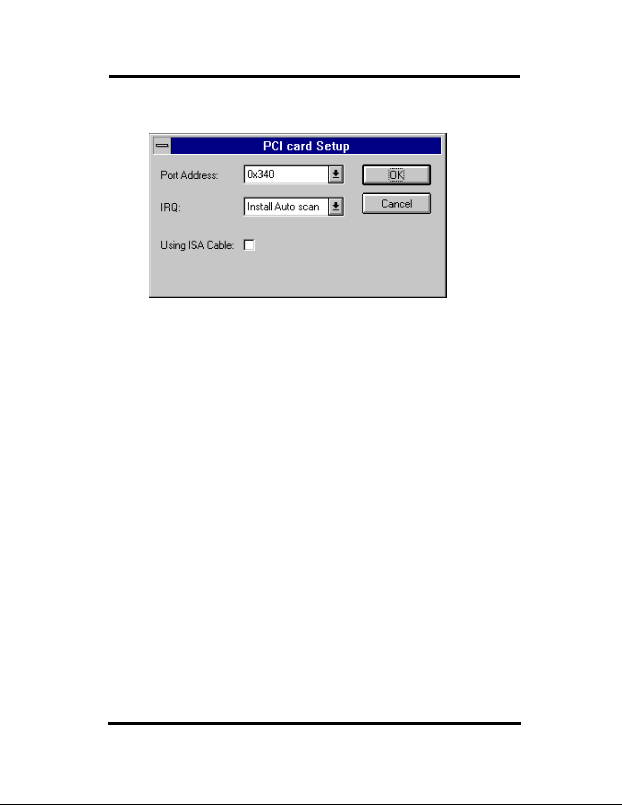
v. If you want to configure the driver to set the PCI card setting, click the PCI Card
Driver Option button in the Install Agfa Driver menu.
vi. Port Address
Set the correct Port Address. Make sure the Port Address is not conflicting with
other devices. All addresses from 0x200 to 0x 3F0 are validPort Aaddresses.
vii. IRQ (Interrupt Request)
Using the Install Auto scan option will enable the installation software to find the
right Interrupt setting for the PCI Card. If auto scan is not successful, please read
item xvii- PCI Configuration for your PC, of this manual for details on how to set
the Interrupt manually.
If you have installed the PCI card on the PC before and you know that a particular IRQ setting will definitely work, then instead of doing an Auto Scan, you can
select that IRQ in the IRQ field directly.
If Auto Scan fails, you should try to use the ISA Paddle Card supplied with the
PCI Card to access Interrupts via the ISA Bus. If you are using the ISA Paddle
Card, make sure you check the Using ISA Cable option.
Valid Interrupts are 3, 5, 7, 9, 10, 11, 12, 15.
ix. Click on OK to return to the Install Agfa Driver menu. You should now configure
the Agfa Output Options.
Page 6
Page 4
INSTALLATION INSTRUCTIONS COMPOSE AGFA PCI I/F CARD
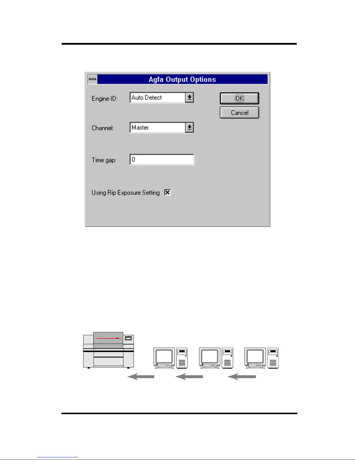
x. Click on the Plugin Options button to configure the Express RIP Plugin.
xi. Engine ID
The Agfa Card can detect which Agfa imagesetters you are driving. Choose the
appropriate engine type if you don’t want to use the Auto Detect option.
xii. Channel
The Channel field is for setting the Channel ID. You should always use the Master
channel if you have only one RIP connected to the Agfa engine. If you have more
than one RIP, the RIP that connects directly to the imagesetter will use the Master
Channel. Other RIPs that are daisy-chained to the Master Channel RIP will use the
Slave Channels 1 to 4.
PCI Board
OUT
PCI Board
OUT
Slave Buffer
Board IN
Slave Buffer
Board IN
PCI Board
OUT
Imagesetter
IN
Slave RIPSlave RIPMaster RIP
Channel ID=Slave 2Channel ID=Slave 1Channel ID=Master
imagesetter
Page 7
Page 5
INSTALLATION INSTRUCTIONS COMPOSE AGFA PCI I/F CARD
In a multiple-RIP configuration you can connect one master RIP and up to four
slave RIPs to the imagesetter. The master RIP is the only RIP directly connected to
the imagesetter. The slave RIPs are daisy-chained to the master RIP using an ISA
Slave Buffer Board. This configuration requires both the PCI Board and a Slave
Buffer Board in all the RIPs, except the Slave RIP at the end of the chain which
requires only a PCI board.
In Multiple RIP configuration an ID mark will be exposed on all output to let the
user know which RIP output the film. If you see one dot at the bottom of the film,
it is output by the Master RIP. Two dots mean it is output by Slave RIP 1. Three
dots mean it is output be Slave RIP 2.
xiii. Time Gap
The TimeGap field is for specifying the time delay between jobs. It should only be
used in multiple-RIP configurations.
A TimeGap of 0 will provide no time delay and the RIP which is currently outputting will occupy the output channel and continue to output until all the jobs in
its active queue has been done. A TimeGap of anything but 0 will introduce a time
delay between jobs so that the other RIP will have a chance of grabbing the output
channel during that time delay. Increasing TimeGap will increase the possibility of
other RIPs taking control of the output channel.
Time Gap should be set to 0 for single RIP installations.
xiv. Using RIP Exposure Setting
If you want the RIP to control the exposure setting, check the Using Rip Exposure
Setting option. When RIP Exposure Control is disabled, the setting on the imagesetter is used.
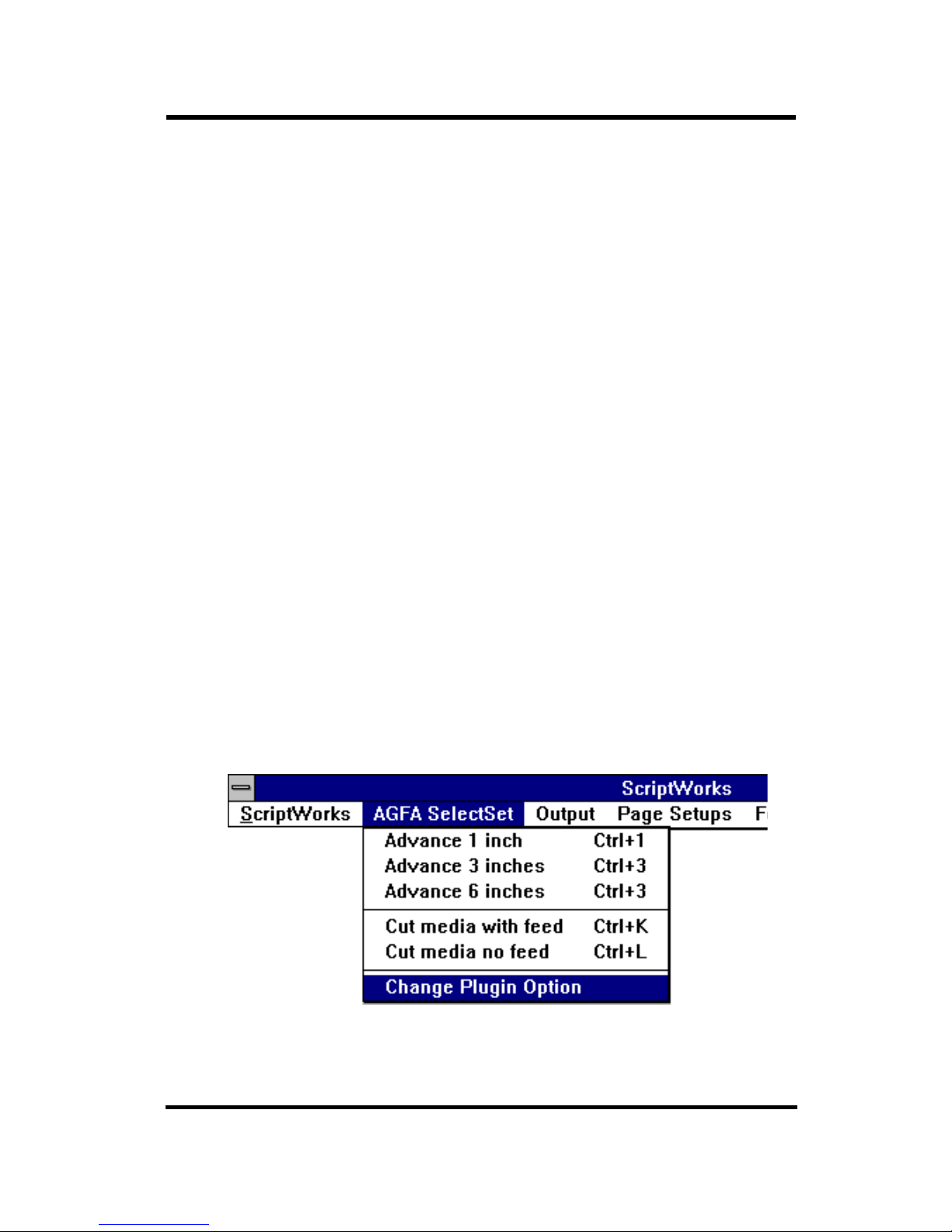
xv. Click on OK after you have finished configuring the Plugin. You can change the
settings in the Agfa Output Options menu by selecting the Change Plugin Option
item in the Output Device menu in the RIP.
Page 8

Page 6
INSTALLATION INSTRUCTIONS COMPOSE AGFA PCI I/F CARD
xvi. After configuring both the PCI Card Driver Options and the Plugin Options, you should
click on the OK button in the Install Agfa Driver menu to install the driver. You will then
see the following messages indicating that the drivers have been copied to the hard drive.
• If the Agfa card is inserted and configured properly. You will see the message:
The interrupt type is ISA if the ISA paddle card is used. If the ISA paddle card is not used,
the interrupt type will be PCI (Level trigger).
• If the Agfa card is not configured properly and the install program cannot find a suitable
Interrupt to assign to the Agfa Card, the installation program will indicate that the
Interrupt routed to is not found.
Please read the next section for a guideline on PCI Configuration for your PC.
• If the card is not inserted properly, you will see the following message cannot scan Agfa
PCI Card..
scan pci card and set interrupt.
cannot scan Agfa PCI card!
scan pci card and set interrupt.
Video card....................found.
CGEN/APIS-PCI ver 1.2.
Serial number.................96120002.
PCI cfg space control.........Plug and Play feature enabled.
PCI cfg int setting...........INTA, IRQ 14.
Interrupt routed to...........not found.
scan pci card and set interrupt.
Video card....................found.
CGEN/APIS-PCI ver 1.2.
Serial number.................96120002.
PCI cfg space control.........Plug and Play feature enabled.
PCI cfg int setting...........INTA, IRQ 14.
Interrupt routed to...........IRQ 10.
Interrupt type................ISA type (edge trigger).
Copy A:\AGFA\agfapci.I32
to c:\express\SW\DEVICES\agfapci.I32.
Copy A:\AGFA\CSLAGFA.SYS
to C:\WINNT35\System32\drivers\CSLAGFA.SYS.
Page 9

Page 7
INSTALLATION INSTRUCTIONS COMPOSE AGFA PCI I/F CARD
xvii. PCI Configuration for your PC
The Compose Agfa PCI interface card is a fully Plug and Play compatible PCI
card. The availability of numerous PCs with numerous versions of BIOS, each with
their own implementation of the PCI Plug and Play standard, has made PCI configuration not as ‘Plug-and-Play’ as it should be. To add to the confusion, most PCI
PCs have ISA , VESA or EISA bus and the PCI controller has no idea what
resources are occupied by the non-PCI cards.
The Agfa PCI interface card is a PCI IDE device. Some PCs does not allow the existence of more than one PCI IDE device in the same PC. Installation of the
Compose card on those PCs using IDE hard disk will not be possible because the
Compose card can not share resources with the PCI IDE hard disk controller. On
those PCs, you must use SCSI hard disk.
On older PCs, the BIOS may not be fully Plug and Play compatible and it might
not be able to assign correct PCI resources to the Compose card. On those PCs, you
can use the supplied ISA paddle card to let the Compose card access ISA
resources.
Since there are many different brands of PCs with many different kinds of BIOS, it
is impossible to write a general guide on PCI configuration that will work with all
PCs. The following is a list of things you should observe while you are doing the
PCI configuration for your PC.
• Make sure the Agfa PCI Card is set to use INTA. If you can assign a PCI Interrupt
Level (A, B, C, or D) to a particular PCI slot in the BIOS, make sure the PCI Slot
the Agfa card is in is set to use PCI INTA.
• If the BIOS doesn’t work with Auto Configuration and you cannot assign PCI
Interrupt Level to ISA Interrupts, then you can try using the ISA paddle card to
access Interrupts using the ISA bus.
• If you are using the ISA paddle card, make sure that the ISA Interrupt you want to
use is not available to or in used by other PCI cards. Some BIOS will let you assign
which interrupts are available to ISA cards and which interrupts are available to
PCI cards. If you are using the ISA paddle card, the Interrupt used by the ISA paddle card must be set to be used by ISA card in the BIOS.
• the Interrupt Requests used by the PCI cards in your PC are not used by ISA,
VESA, or EISA cards,
• the Interrupt Request used by a PCI card is not used by another PCI card in your
PC,
• the memory address needed by some ISA cards are not reserved by the PCI controller. Some BIOS will also let the user reserve a range of memory address to be
Page 10

Page 8
INSTALLATION INSTRUCTIONS COMPOSE AGFA PCI I/F CARD
used by an ISA card. If you have an ISA card (e.g. the SMC Elite16Ultra ethernet
card) that uses memory address, you must reserve the location it uses or else your
ISA card will not be able to access that memory location.
Page 11
Page 9
INSTALLATION INSTRUCTIONS COMPOSE AGFA PCI I/F CARD
4. Switch OFF the machines and connect the RIP to the imagesetter. The cable required is
supplied and is the same for all models of Agfa imagesetters. Ensure that the screwlocks
are fully tightened at the Agfa. Always connect or remove the cable when the
machines are switched off
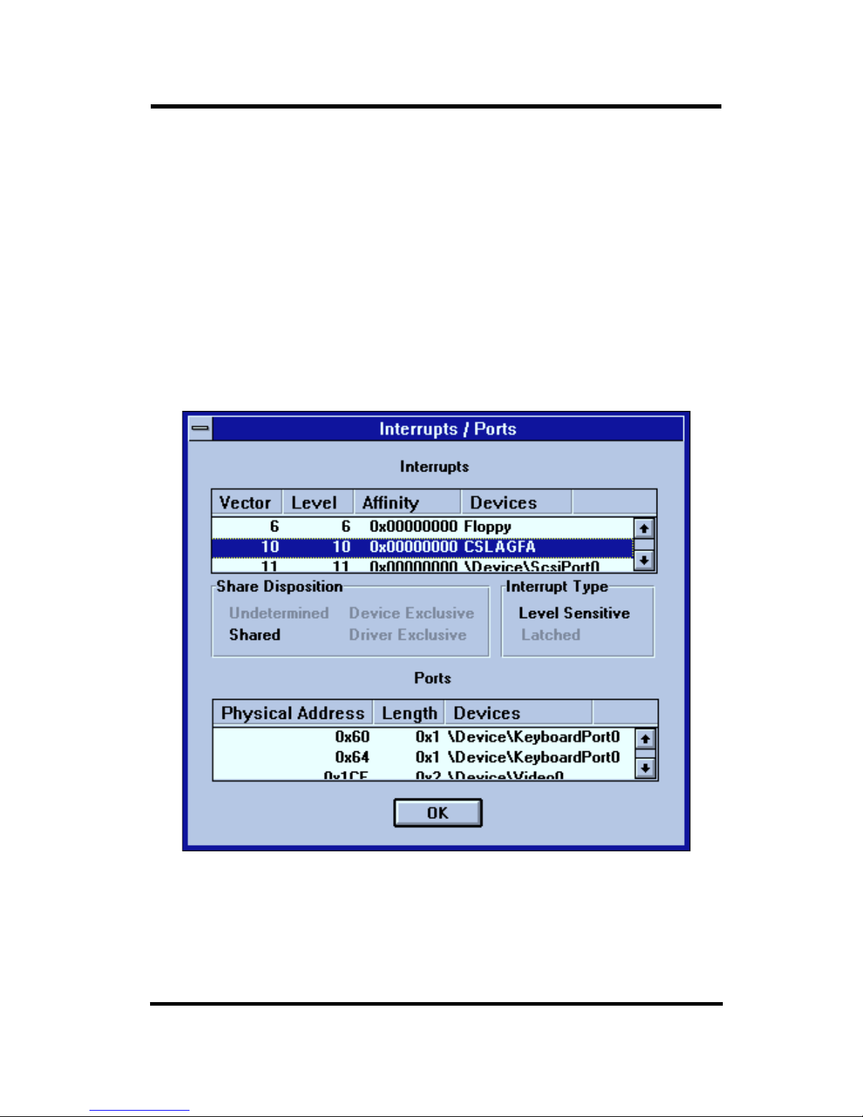
5. You can use the WINDOWS NT DIAGNOSTICS application to check whether the interface card is able to access the IRQ you have selected. This application can be found in
the Group ADMINISTRATIVE TOOLS. Alternatively, you can choose RUN in the FILE
manual in the Program Manager and type in WINMSD. When you are in the DIAGNOSTICS application, click on the INTERRUPTS/PORTS button and you will be able to
check the interrupts used by all installed devices.
For example, if you are using IRQ 10 for the Agfa interface Card:
• use the scroll button on the top text box to scroll to the appropriate IRQ Vector. Check
that the Device name in the Devices field is CSLAGFA, as shown below.
Page 12
Page 10
INSTALLATION INSTRUCTIONS COMPOSE AGFA PCI I/F CARD
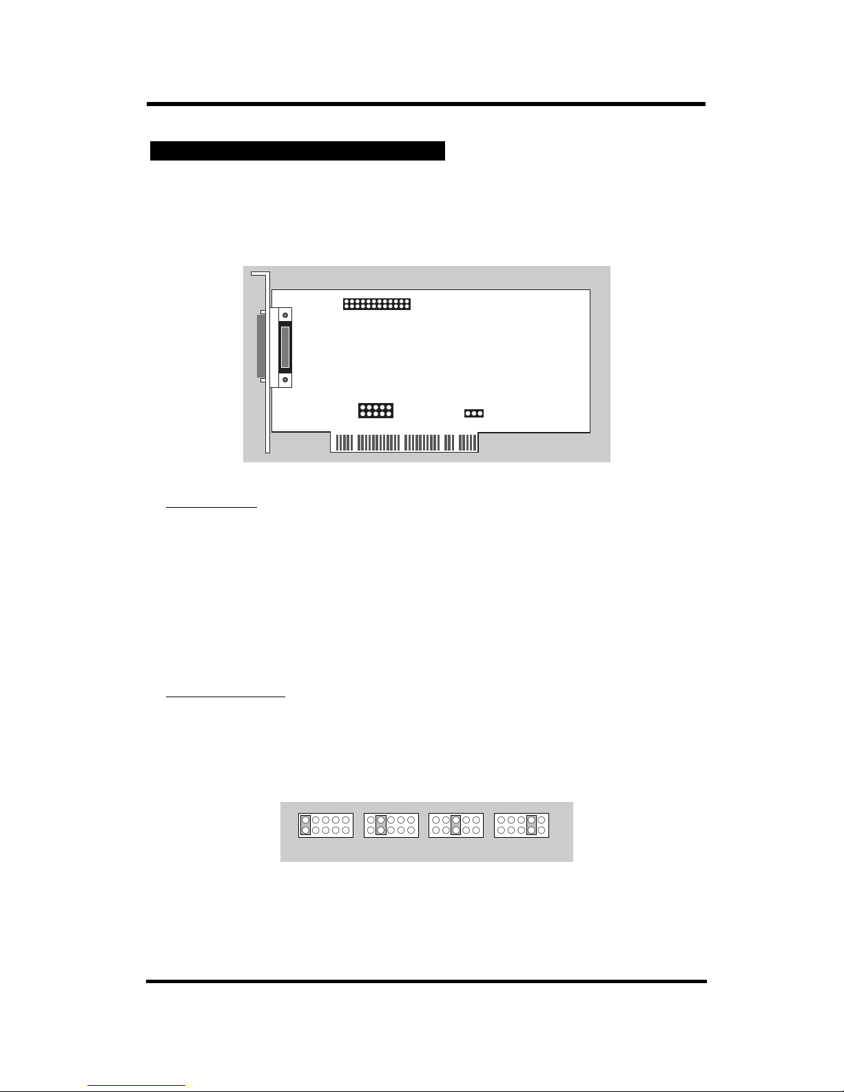
The Agfa card has two jumper blocks for User configuration. The jumper block JP3 is
used for setting the PCI interrupt level or for connection to the ISA paddle-card. The
jumper block JP2 is for setting the PCI configuration mode.
Auxiliary Port
(for Multiple-RIP)
The Auxillary Port allows you to connect the Agfa PCI Card to an ISA Slave Buffer Card
in a multiple-RIP configuration. In a multiple-RIP configuration you can connect one
master RIP and up to three slave RIPs to the imagesetter. The master RIP is the only RIP
directly connected to the imagesetter. The slave RIPs are daisy-chained to the master
RIP using the ISA Slave Buffer Board. This configuration requires both the PCI Board
and a Slave Buffer Board in all the RIPs, except the Slave RIP at the end of the chain
which requires only a PCI board.
PCI Interr
upt Level
Jumper JP3 is for setting the PCI Interrupt Level You can set the PCI Interrupt Level
manually when you are not using the Auto-Configuration mode. If you are using the
Auto-Configuration mode, make sure that JP3 is set to use INTA.
After changing the Interrupt Level on the card, you have to set the correct value in the
Configuration file for the driver as mentioned in the previous section.If the ISA Paddle
Card is needed, you should use JP3 to connect the PCI card to the ISA Paddle Card.
INTA INTB INTC INTD
JP3 Settings
JP1
A B C D
Set PCI Interrupt Level
JP2
1 2 3
PCI Auto-Configuration
2
1
26
25
JP3
Connector for
Auxillary Port
Compose Agfa PCI Interface card
3. AGFA PCI CARD CONFIGURATION
Page 13
Page 11
INSTALLATION INSTRUCTIONS
COMPOSE Agfa PCI I/F CARD
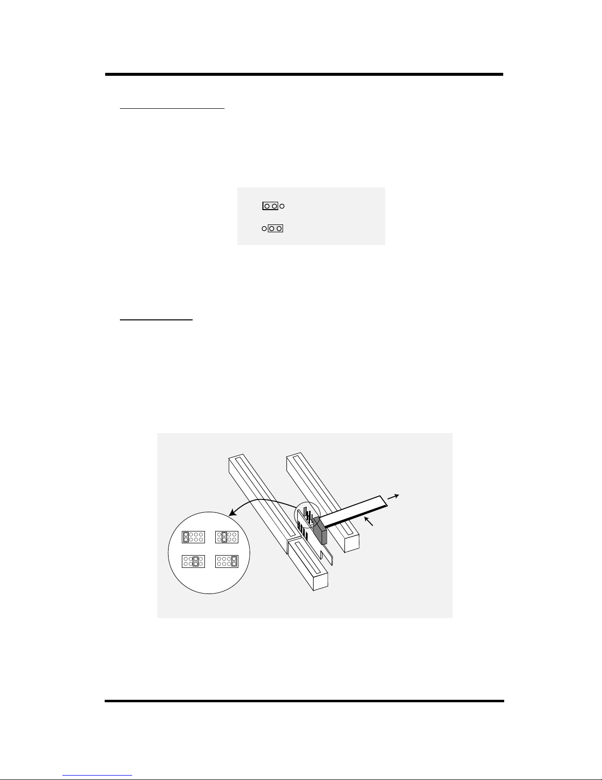
PCI Auto Configuration
Jumper JP2 is for setting the Auto-Configuration mode of the card. The Compose
Exxtra-Ultre PCI Interface card is a fully Plug and Play compatible card. To accommodate older PCI controller on some PCs, the jumper JP2 on the card can be set to let the
user configure the PCI setting of the card.
Set the jumper to position 1-2 if you want the PCI controller to configure the card.
Set the jumper to position 2-3 if you want to configure the card manually.
ISA Paddle Car
d
If the ISA Paddle Card is needed, you should remove the jumper from JP3, connect JP3
to the ISA Paddle Card using the flat cable supplied. Make sure that the Red line on the
flat cable is aligned to Pin 1 and 2 on the ISA Paddle Card. The Red line should align
with the INTA pins on JP3.
Insert the jumper removed from JP3 onto the ISA Paddle Card to select an appropriate
Interrupt Request. The jumper block allows you to set the PCI card to use IRQ 10, 11, 12
or 15.
16-bit ISA slot PCI slot
ISA Paddle
Card
Flat cable
red line on
pin 1&2
IRQ10 IRQ11
IRQ12 IRQ15
To JP3 on
PCI card
JP2
JP2
Auto-Configuration
BIOS & Driver Control
1 2 3
1 2 3
JP2 configuration
Page 14

Page 12
INSTALLATION INSTRUCTIONS COMPOSE AGFA PCI I/F CARD
1. AGFA PCI CARD VERSIONS
Please note that there are 3 different versions of Agfa Interface Card. You cannot use
the SelectSet card to drive the Avantra. You cannot use the AccuSet card to drive the
SelectSet. If you are using the SelectSet card but the RIP is connected to an Avantra, you
won’t be able to access the device in the Page Setup menu and a message in the System
Monitor will tell you that you are using the wrong card.
APPENDIX
Page 15

Page 13
INSTALLATION INSTRUCTIONS COMPOSE AGFA PCI I/F CARD
Agfa Imagesetter Information
• Please set the Cassette width in the Cassette Manager according to the Supply Cassette Width settings.
• The Exposure setting is for adjusting the laser intensity of the imagesetter. To make the image darker, you should increase the
Exposure setting.
• For drum models (SelectSet or Avantra), the image height must be 0.3" less than the paper width.
For example, the maximum imaging are of SelectSet 5000 is
22" (Width) x 15.7" (Height).
2. AGFA IMAGESETTER INFORMATION
Supply Cassette Max. Image Resolution Media Type Exposure Default
Width (inch) W x H (inch) (dpi) Exposure
ProSet 9400 13.6 13.6 x 99.0 1200, 2400 Film, Paper 0 - 255 180
ProSet 9600 13.6 13.6 x 99.0 1200, 2400 Film, Paper 0 - 255 180
ProSet 9700 27.3 27.3 x 99.0 1200, 2400 Film, Paper 0 - 255 180
ProSet 9800 13.6 13.6 x 99.0 1200, 2400 Film, Paper 0 - 255 180
ProSet 9550 13.6 13.6 x 99.0 1200, 2400 Film, Paper, Plate 0 - 255 180
ProSet 9836 13.6 13.6 x 99.0 1200, 2400, 3600 Film, Paper, Plate 0 - 255 180
AccuSet 800 14 14 x 99.0 600, 1200, 1800, 2400 Film, Paper, Plate 0 - 255 180
AccuSet 1000 14 14 x 99.0 600, 1200, 1800, 2400, 3000 Film, Paper 0 - 255 180
AccuSet 1400 14 14 x 99.0 600, 1200, 1800, 2400, 3000 Film, Paper 0 - 255 180
AccuSet 1500 14 14 x 99.0 1200, 1800, 2400, 3000 Film, Paper 0 - 255 180
SelectSet 5000 10, 13, 16 22.0 x 16.0 1200, 2400, 3600 Film, Paper, 0 - 999 600
SelectSet 7000 13, 16, 26 22.0 x 26.0 1200, 2400, 3600 Film, Paper, Plate 0 - 999 600
Avantra 20 10,12,13.3,14 20.0 x 13.7 1200, 1800, 2400, 3600 Film, Paper 0 - 1430 600
Avantra 25/25S 10,12,13.3,14,18 25.0 x 17.7 1200, 1800, 2400, 3600 Film, Paper 0 - 1430 600
Avantra 30 14,16,18,20,24,26,28,30 30.0 x 24.7 1200, 1800, 2400, 3600 Film, Paper, Plate 0 - 1430 600
Avantra 36/36S 16,18,20,24,28.5,30,32,36 28.5 x 35.7 1200, 1800, 2400, 3600 Film, Paper, Plate 0 - 1430 600
Avantra 44/44S 16,18,20,24,28.5,30,32,36 44.5 x 35.7 1200, 1800, 2400, 3600 Film, Paper, Plate 0 - 1430 600
Page 16

Page 14
INSTALLATION INSTRUCTIONS COMPOSE AGFA PCI I/F CARD
3. AGFA DRIVER CONFIGURATION FILE
After installation, a Driver Init file AGFAPCI.INI is created in the
C:\EXPRESS\SW\DEVICES\CONFIG
directory where EXPRESS is the directory you installed the Harlequin RIP. All settings
in this Init file can be modified in the Change Plugin Option in the RIP.
AGFA PCI Driver Init File (AGFAPCI.INI)
[AGFAPCI]
EngineID=0
CHANNEL=0
TIMEGAP=0
EXPOSURE=1
SERIALNUM=0
CASS=0
EngineID 0 Auto detect during startup
1000/1500 AccuSet 1000/1500
9400/9550/9600/9700 ProSet 9400/9550/9600/9700/
9800/9836 ProSet 9800/9836
2400/5000/7000 SelectSet 2400/5000/7000
20/25/36/44 Avantra 20/25/36/44
This field corresponds to Plugin Option [Engine ID].
CHANNEL 0 Single RIP or Master RIP
1/2/3/4/5/6/7 Slave 1/2/3/4/5/6/7
This field corresponds to Plugin Option [Channel].
TIMEGAP 0 Time gap between pages
This field corresponds to Plugin Option [Time Gap].
EXPOSURE 1 Using RIP exposure setting
0 Do not use RIP exposure setting
This field corresponds to Plugin Option [Using RIP Exposure Setting].
SERIALNUM 0 Not used in this version
CASS 0 Not used in this version
Page 17

Page 15
INSTALLATION INSTRUCTIONS COMPOSE AGFA PCI I/F CARD
4. EDGE TO EDGE (ETOE) FEATURE
Compose Agfa Interface Card of version 1.3 onwards will now support the Edge to
Edge feature. By the new card, full width will be supported.
5. AGFA DRIVER FILES
After installation, three files will be copied onto your hard drive.
AGFAPCI.I32 RIP output plugin driver.
Installed in C:\EXPRESS\DEVICES
AGFAPCI.INI A configuration file used by the plugin driver.
Installed in C:\EXPRESS\DEVICES\CONFIG
CSLAGFA.SYS NT kernel mode hardware driver for PCI card.
Installed in C:\WINNT35\System32\drivers\CSLAGFA.SYS.
 Loading...