

Page 1
Compool
Lx220 SOLAR CONTROL SYSTEM
Installation & Operating Instructions
03/22/00
941-0809
Page 2

Page 3

Compool Lx220
Table of Contents
Table of Contents . . . . . . . . . . . . . . . . . . . . . . . . . . . . . . . . . . . . . . . . . . . . . . . . . . . . . . . . 1
Safety Notice. . . . . . . . . . . . . . . . . . . . . . . . . . . . . . . . . . . . . . . . . . . . . . . . . . . . . . . . . . . . 2
Important Safety Instructions . . . . . . . . . . . . . . . . . . . . . . . . . . . . . . . . . . . . . . 2
Introduction. . . . . . . . . . . . . . . . . . . . . . . . . . . . . . . . . . . . . . . . . . . . . . . . . . . . . . . . . . . . . 3
Package Contents . . . . . . . . . . . . . . . . . . . . . . . . . . . . . . . . . . . . . . . . . . . . . . . 3
Plumbing Requirements . . . . . . . . . . . . . . . . . . . . . . . . . . . . . . . . . . . . . . . . . . 4
Installation Instructions. . . . . . . . . . . . . . . . . . . . . . . . . . . . . . . . . . . . . . . . . . . . . . . . . . . . 5
Solar Control. . . . . . . . . . . . . . . . . . . . . . . . . . . . . . . . . . . . . . . . . . . . . . . . . . . 5
Valve Actuator . . . . . . . . . . . . . . . . . . . . . . . . . . . . . . . . . . . . . . . . . . . . . . . . . 5
Water Sensor. . . . . . . . . . . . . . . . . . . . . . . . . . . . . . . . . . . . . . . . . . . . . . . . . . . 6
Solar Sensor . . . . . . . . . . . . . . . . . . . . . . . . . . . . . . . . . . . . . . . . . . . . . . . . . . . 6
High Voltage Wiring . . . . . . . . . . . . . . . . . . . . . . . . . . . . . . . . . . . . . . . . . . . . 6
Pool Cleaner Protection . . . . . . . . . . . . . . . . . . . . . . . . . . . . . . . . . . . . . . . . . . 7
Solar Booster Pump Control. . . . . . . . . . . . . . . . . . . . . . . . . . . . . . . . . . . . . . . 7
Second Valve Actuator. . . . . . . . . . . . . . . . . . . . . . . . . . . . . . . . . . . . . . . . . . . 8
System Start-up. . . . . . . . . . . . . . . . . . . . . . . . . . . . . . . . . . . . . . . . . . . . . . . . . 8
1
Operating Instructions. . . . . . . . . . . . . . . . . . . . . . . . . . . . . . . . . . . . . . . . . . . . . . . . . . . . . 9
Water Flow To Panels Switch . . . . . . . . . . . . . . . . . . . . . . . . . . . . . . . . . . . . . 9
Water Temperature Dial . . . . . . . . . . . . . . . . . . . . . . . . . . . . . . . . . . . . . . . . . . 9
Power On Light. . . . . . . . . . . . . . . . . . . . . . . . . . . . . . . . . . . . . . . . . . . . . . . . . 9
Solar On Light . . . . . . . . . . . . . . . . . . . . . . . . . . . . . . . . . . . . . . . . . . . . . . . . . 9
Pool Cleaner Delay Expired Light . . . . . . . . . . . . . . . . . . . . . . . . . . . . . . . . . . 9
Water/Solar Sensor Service Required Lights . . . . . . . . . . . . . . . . . . . . . . . . . 10
Push To Reset Power Button . . . . . . . . . . . . . . . . . . . . . . . . . . . . . . . . . . . . . 10
Winterizing Instructions . . . . . . . . . . . . . . . . . . . . . . . . . . . . . . . . . . . . . . . . . 10
Problem Solving . . . . . . . . . . . . . . . . . . . . . . . . . . . . . . . . . . . . . . . . . . . . . . . . . . . . . . . . 11
Power On Light Does Not Illuminate. . . . . . . . . . . . . . . . . . . . . . . . . . . . . . . 11
Solar On Light Does Not Illuminate. . . . . . . . . . . . . . . . . . . . . . . . . . . . . . . . 11
Solar On Light Is Always Illuminated . . . . . . . . . . . . . . . . . . . . . . . . . . . . . . 11
Water Flow To Panels Switch Does Not Operate The Valve Actuator . . . . . 11
Checking The Temperature Sensors. . . . . . . . . . . . . . . . . . . . . . . . . . . . . . . . 11
Warranty . . . . . . . . . . . . . . . . . . . . . . . . . . . . . . . . . . . . . . . . . . . . . . . . . . . . . . . . . . . . . . 13
Index . . . . . . . . . . . . . . . . . . . . . . . . . . . . . . . . . . . . . . . . . . . . . . . . . . . . . . . . . . . . . . . . . 14
Page 4

2
Safety Not i c e
Important Safety Instructions
When installing and using this electrical equipment, basic safety precautions should always be
followed, including the following:
READ AND FOLLOW ALL INSTRUCTIONS.
WARNING
they are closely supervised at all times.
Compool Lx220
- To reduce the risk of injury, do not permit children to use this product unless
WARNING
A green colored terminal (marked “G”) is located inside the high voltage compartment of
the LX-220 Solar Control. To reduce the risk of electric shock, this terminal must be
connected to the grounding means provided in the electrical supply service panel with a
continuous copper wire equivalent in size to the circuit conductors supplying this
equipment.
SAVE THESE INSTRUCTIONS.
- Water in excess of 100 degrees Fa hren heit may be hazardous to your health.
Page 5
Compool Lx220
Introduction
Package Contents
3
The LX220 Control System is a basic differential temperature control designed especially for
solar-heated Swimming Pool applications. Whenever solar energy is available, the Control will
automatically activate a motorized three-port Solar Valve and/or a Solar Booster Pump.
Remember to set the filter pump timer so that the filter pump is operating during that time of the
day when solar energy is available.
If the Swimming Po ol u t ilizes a pool cleaner booster pump, the Control wi l l op tio nal ly di sab l e
the pump for a period of 4 minutes whenever the solar syst em turns on. This protects the pump
from possible damage caused by residual air within the solar panels.
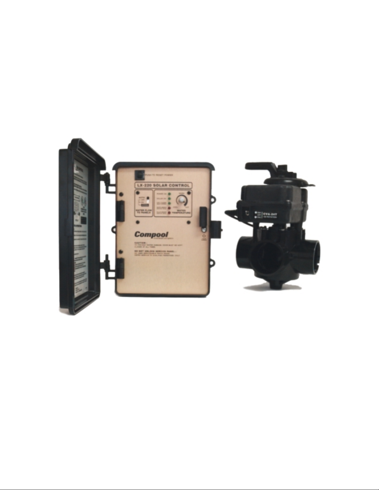
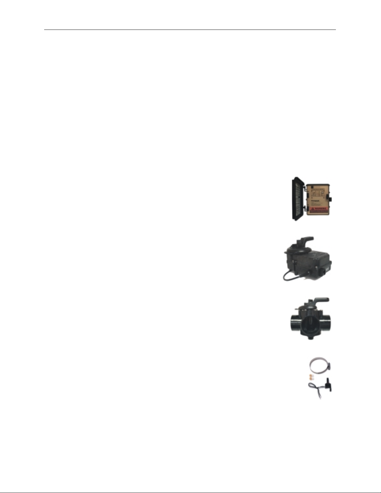
The LX220/2TX Solar Valve Control System includes the following components:
LX-220 Solar Control
CVA-24T Valve Actuator
PTV-2TS 3-Port Valve
TS-5T Temperature Sensor (2 qty.)
Note: The System is also available without Valve and Valve Actuator. Order LX220/B Solar
Booster Pump System.
Tools Required: 5/16” Drill for Water Sensor. Cable for Solar Sensor.
Page 6

4
Plumbing Requirements
Compool Lx220
Plumb system in accordance with recommended hydraulic schematic.
2” dia. plumbing i s ad vised t o ens ure max imum flow of wa ter th rough the solar panel s. A s olar
booster pump should be added if panels are installed at a very high elevation.
It is recommended that the solar panels are mounted in a way that gravity will allow draining
whenever the filter pump is not on.
For systems with glazed panels, damage can occur from overheating if the filter pump is still
running after the solar has turned off. To enable gla zed panels to au tomatically drain wh enever
the solar turns off (even if the filter pump is still running), a 1/2” motorized Solar Drain Valve
(model HW-5B) should be plumbed from the solar feed line, through a check valve, to a zero
psi point (such as pool fill line or jet air intake).
Page 7

Compool Lx220
Installation Instructions
Solar Control
Select a convenient location to mount the Control, making sure that the location is greater than
5 feet from the Pool or Spa and no further than 15 feet from the Solar Valve. Wall-mount the
Control, using appropriate screws through the three exter nal mounting points located on the side
of the enclosure.
5
Valve Actuator
Mount Valve Actuator to solar valve using the 4 mounting screws provided. Run cable to solar
control. Loosen LOCK SCREW on service panel of Solar Co ntrol, and swing open to expose
the high voltage and low voltage compartments. Insert Valve Actuator cable through hole on
bottom left si de of Solar Control , and plug into circuit board at VLV1 so cket.
Page 8

6
Water Sensor
Solar Sensor
Compool Lx220
Select a convenient location to mount the Water Sensor in the plumbing system between the
filter pump and filter. Drill a 5/16” dia. hole in one side of pipe, and install one of the
Temperature Sensors (included) in accordance with instructions provided. Run 22 gauge 2conductor cable (included) between the Sensor and low voltage compartment of the Solar
Control. Use waterpr oof connectors ( provided) to connect Sensor to cable. A t the Solar Cont rol,
strip insulation 1/4” and connect to the circuit board at WATER SENSOR screw terminals.
Install the other Temperature Sensor at the solar panel array, or any sunny location.
WARNING: DO NOT DRILL HOLE AND CLAMP SENSOR INTO SOLAR PIPE
glazed panels, install Sensor between collector and glazing. Run 2-conducto r cable between the
Sensor and the Solar Control. Use waterproof connectors (provided) to connect Sensor to cable.
At the Solar Control, strip insulation 1/4” and connect cable to the circuit board at SOLAR
SENSOR screw terminals.
. For
High Voltage Wiring
The high voltage wiring section is located behind the service panel in the lower right side
compartment of the Solar Control. Holes are provided on bottom of enclosure for conduit
mounting. The Solar Control can be connected either to 115VAC or 230VAC. The Solar
Control should be wired so that it gets contin uou s po wer (connect to Line-Side of Time Clock
or directly to sub-panel).
Page 9

Compool Lx220
Pool Cleaner Protection
Recommended for use in pool systems which utilize a “booster pump” pool cleaner. This feature
automatically turns off the pool cleaner pump for a few minutes whenever solar is initiated. This
will protect the pump from damage caused by air in the solar panels at system start-up.
7
Install Relay Kit (model RLY-SC) at the Solar Control in accordance with instructions
provided, and plug low-voltage connector onto circuit board at SWP Socket. Using wire nuts,
connect Black wires to Load connections of P ool Cleaner Time Clock, and connect Red wires
to the Pool Cleaner Pump.
Solar Booster Pump Control
If a solar booster pump is being used, install a Relay kit (model RLY-SC) at the Solar Control
in accordance with instructions provided.
Plug low-voltage connector onto circuit board at PMP Socket. Using wire nuts, connect Black
wires to 115VAC or 230VAC Line V oltage, an d connect Red wires to t he Solar Booster Pum p.
Page 10

8
Second Valve Actuator
It is possible to control a maximum of two Valve Actuators. Plug the second Valve Actuator
into VLV2 socket.
Compool Lx220
System Start-up
Apply power to the system.
Place the WATER FLOW TO PANELS Switch in the “OFF” position. The POWER ON and
POOL CLEANER DELAY EXPIRED Lights should come on.
If pool cleaner protection has been ad ded to the system, th e pool cleaner pum p motor should be
activated whenever the pool cleaner timer is on . Momentarily turn poo l cleaner timer on and off
to check that the motor is operating correctly.
Check that Solar Valve is in “solar bypass” position, diverting water away from solar panels. If
Solar Valve is staged incorrectly (ie: diverting water to the solar panels), reverse switch on back
of Valve Actuator (change from ON1 to ON2, or vice-versa). The Valve Actuator will
automatically rotate to the correct position.
Place the WATER FLOW TO PANELS Switch in the “ON” position. The POOL CLEANER
DELAY EXPIRED Light will turn off, and the SOLAR ON Light will come on. Check that
Solar Valve has rotated from the “solar bypass” position to the “solar” position, diverting water
through the solar panels.
Place the WATER FLOW TO PANELS Switch in the “AUTO” position.
The system is now ready to be operated as desired.
Page 11

Compool Lx220
Operating Instructions
Water Flow To Panels Switch
AUTO:
left in this position during normal use.
Automatically turns system on whenever solar energy is available. Switch should be
9
OFF:
Manually turns solar system off.
ON:
Manually turns solar system on, regardless of solar availability. This position should be
used only to t est system opera tion.
Water Temperature Dial
Allows solar system to heat the water up to set temperature. After that temperature is reached,
the solar system is automatically turned off. The Dial ranges from approximately 74 - 110
degrees Fahrenheit
To determine your optimum temperature setting, set Dial to the “HOT” position and observe the
water temperature over a period of a few day s. When the m aximum des i red temp eratur e of the
pool is reached, rotate the Dial counterclockwise until the SOLAR ON Light just goes out. Once
this setting is identified, it will not be necessary to change the Dial.
Po wer On Light
When Lit, indicates that electrical power is applied to the Control.
Solar On Light
When lit, indicates that solar system is on.
filter pump operates during that time of the day when solar energy is available.
Pool Cleaner Delay Expired Light
Whenever the solar system is turned on, an electronic delay automatically turns off the pool
cleaner for a few minutes. This protects the pu mp from damage caused b y air in the solar panels
at system start-up.
added to the Control. This light indicates that the delay has expired.
Note:
the filter pump timer must be set so that the
Note:
to enable this feature, an optional Relay Kit (model RLY-SC) must be
Page 12

10
Water/Solar Sensor Service Required Lights
The Control incorporates electronic Sensors to monitor t he water and solar temperatures. If a
Sensor should malfunction or the cable to the Sensor become damaged, the appropriate
SENSOR SERVICE REQUIRED Light will come on. This indicates that the Sensor and its
wiring connections should be inspected by your Pool Serviceperson.
Replace defective Sensor with 10K Thermistor Sensor (Compool model TS-5T).
Push To Reset Power Button
An internal circuit breaker protects the Solar Valve and control circuitry from electrical
overload situations. A tripped breaker is indicated by a white tab. Check for short circuit
conditions before resetting. Push to reset.
Compool Lx220
Caution:
Winterizing Instructions
Each year, at the onset of winter, it is advisable to remove all water from the solar system, and
prevent any new water from entering the solar panels during the wi nter months.
To disable the Solar Control during the winter months, place the WATER FLOW TO PANELS
Switch in the OFF position.
Note:
Do not attempt to pry out tab.
Freeze damage is not covered under System Warranty.
Page 13

Compool Lx220
Problem Solving
Power On Light Does Not Illuminate
Verify the circuit breaker at sub-panel is not tripped. If the 3-amp Circuit Breaker on the LX220 is tripped, it is most often due to a defective Circuit Board or Valve Actuator. Try
disconnecting each one separately to determine which one is at fault.
Solar On Light Does Not Illuminate
The SOLAR ON light will only illuminate when the solar temperature is 5 degrees warmer than
the water temperature.
Check the SENSOR SERVICE REQUIRED Lights on the LX-220 Solar Control. If either Light
is illuminated, inspect the appropriate cable and wire connections and replace the appropriate
Temperature Sensor if necessary . An ohm meter can be used to take a reading of the Sensors.
See Table 1.
If the Temperature Sensors are not at fault, replace the Circuit Board.
Solar On Light Is Always Illuminated
Check the SENSOR SERVICE REQUIRED Lights on the LX-220 Solar Control. If either Light
is illuminated, inspect the appropriate cable and wire connections and replace the appropriate
Temperature Sensor if necessary. An ohm meter can be used to take a reading of the
Temperature Sensors. See Table 1.
11
If the Temperature Sensors are not at fault, replace the Circuit Board.
Water Flow To Panels Switch Does Not Operate The Valve Actuator
If the Valve Actuator does not operate when using the WATER FLOW TO PANELS Switch
(sliding switch between ON and OFF), either the Valve Actuator or the Circuit Board is at fault.
First verify that the toggle switch located on the Valve Actuator is either in t he ON1 or ON2
position.
With a voltmeter, check the output voltage of the VLV1 so cket located on the LX-220 Circuit
Board. When the WATER FLOW TO PANELS Switch is in the OFF position, the top and
middle pins should read 24 VAC. When the WATER FLOW TO PANELS switch is in the ON
position, the top and bottom pins should read 24 VAC.
If voltage readings are correct, replace the Valve Actuator. If voltage readings are incorrect,
replace the Circuit Board.
Checking The Temperature Sensors
Disconnect Temperature Sensor wires from the circuit board, and test sensor using an ohm
meter. See Table 1.
Page 14

12
Compool Lx220
Table 1:
DEG. F OHMS
30 34574
35 30008
40 26109
45 22771
50 19906
55 17440
60 15314
65 13477
70 11884
75 10502
80 9299
85 8250
90 7333
95 6531
100 5827
105 5208
110 4663
115 4183
120 3758
125 3382
130 3048
135 2752
Page 15

Compool Lx220
Warranty
13
Compool, Inc. warrants to the purchaser of this electronic con trol system, for the period of one
year from the date of original purchase for use, that any defective product proved to be caused
by faulty workmanship or fa ulty material, will be repaired or replaced at Compool’s option at
no charge, providing the product is returned to Compool with all transportation charges prepaid.
This warranty covers the Solar Control and Valve Actuator. It extends to the first retail
purchaser and any subsequent owners of the system.
This limited warranty applies only to controls which have been installed and maintained in strict
accordance with installation and operating instructions provided by Compool, Inc., using
installation hardware supplied and/or recommended in writing by Compool, and to controls
which have been connected to the correct supply voltage.
This limited warranty does not apply to any controls which have been repaired or altered by
anyone other than Compool or a person authorized by it; or which have been subject to mi suse,
neglect or accident; or which have been damaged by wind, rain, lightning, freezing or other
cause, thing, person, or act of God; or which have been subject to damage in transit, during
installation, or by someone o ther than Compool, Inc.; or which have been damaged because of
a defect in a component or part which is not p art of the Compool Control System; or upon which
the serial number or manufacture date has been altered, effaced or removed.
This warranty gives you specific legal rights and you may also have other rights which vary
from State to State. Compool, Inc. does not authorize any person to create any other obligation
or liability in connection with Compool controls.
Compool, Inc. makes no warranty of merchantability or fitness for any use. Any implied
warranty applicable to Compool controls is limited in duration to the duration of this written
warranty. Unless state law provides otherwise, Compool, Inc. shall not be liable for
consequential or incidental damages resulting from breach of this written warranty or any
implied warranty, or any inconvenience, loss of time, or incidental expenses such as telephone
calls.
Compool, Inc. shall not be liable for any labor charges associated with the removal or
reinstallation of any so-claimed defective products.
To exercise this warranty, send defective parts, with copy of dated receipt and a brief description
of the problems encountered, postage prepai d, to:
Compool, Inc.
599 Fairchild Drive
Mountain View, California 94043
For questions, repairs, replacement parts, or information on possible Authorized Service
Centers within your vicinity call:
Compool, 800-458-2201 or 650-964-2201, Monday - Friday, 8:00 - 5:00 Pacific Time.
Or visit us on the internet at compool.com
Page 16

14
Index
Checking The Temperature Sensors 11
High Voltage Wiring 6
Important Safety Instructions 2
Index 14
Installation Instructions 5
Introduction 3
Operating Instructions 9
Package Contents 3
Plumbing Requirements 4
Pool Cleaner Delay Expired Light 9
Pool Cleaner Protection 7
Power On Light 9
Power On Light Does Not Illuminate 11
Problem Solving 11
Push To Reset Power Button 10
Safety Notice 2
Second Valve Actuator 8
Solar Booster Pump Control 7
Solar Control 5
Solar On Light 9
Solar On Light Does Not Illuminate 11
Solar On Light Is Always Illuminated 11
Solar Sensor 6
System Start-up 8
Table of Contents 1
Valve Actuator 5
Warranty 13
Water Flow To Panels Switch 9
Water Flow To Panels Switch Does Not Operate The Valve Actuator 11
Water Sensor 6
Water Temperature Dial 9
Water/Solar Sensor Service Required Lights 10
Winterizing Instructions 10
Compool Lx220
 Loading...