

Page 1

- 0 -
Page 2
- 1 -
Part: # REC02F
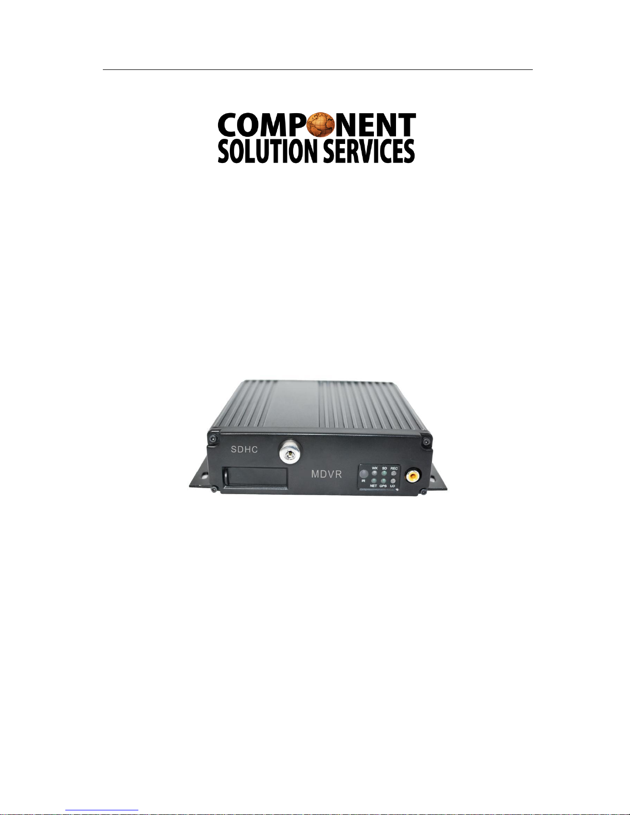
MDVR GUIDE
Mobile Digital Video Recorder
Corporate Office
P.O. Box 245 Spring Lake, MI 49456
616.414.0505
fax: 866.496.6155
Elkhart Office/ Technical Support
574.584.3770
Page 3

- 2 -
Contents
Introduction ...............................................................................................................................4
Features….................................................................................................................... ......4
Camera Placement….............................................................................................................5
In-vehicle Cameras …........................................................................................................5
Recording & Playback …........................................................................................................6
System Start-Up ..............................................................................................................6
System Shut-Down ..........................................................................................................6
Playback Options ................................................................................................................6
TV Video Output (Front and Back) ....................................................................................6
Removable Hard Drive USB Connection ...........................................................................6
Front Panel USB Connection ............................................................................................6
MDVR Layout …........................................................... ............................................................7
Front Panel ….…................................... .. .. ..............................................................7
Back Panel …...... ... ...................... ..... ... ...............................................................8
Installation …..............................................................................................................................9
Proper Mounting Location….......................................................................................................9
Installation Instructions…......................................................................................................10
System Power Wiring…...........................................................................................................11
IR Remote Instructions….........................................................................................................12
Menu Configuration…...............................................................................................................14
Login Page…........................................................................................................................14
Main Menu Page….................................................................................................................15
Date and Time…............................................................................................................... 16
Record …...........................................................................................................................17
General Options….......................................................................................................17
Camera Setup…...........................................................................................................19
Record Schedule….......................................................................................................20
HDD Management…...........................................................................................................21
Disk Format…...................................................................... .........................................22
Network….............................................................................................................................23
DVR IP Options…..........................................................................................................23
WIFI…............................................................................................................................24
3G….............................................................................................................................25
Server….........................................................................................................................26
General…............................................................................................................................27
Vehicle Startup and Shutdown…...................................................................................27
Driver & Company Info….............................................................................................28
Insert Info ….............................................................................................................. 29
Buzzer Setup…............................................................................................................20
Security…..............................................................................................................................31
Page 4

- 3 -
System Level..................................................... ............. ...................................................32
Firmware Upgrade….....................................................................................................33
Reset Default….............................................................................................................35
Alarm…................................................................................................................................37
I/O Input…....................................... ..............................................................................37
G-sensor…..................................................................................................................38
Speed Limit…....................................................................................................................39
Search…............................................................................................................................40
Log …...............................................................................................................................42
System Info ….....................................................................................................................44
Modules…................................................................................................................ 44
History…............................................................... ....................................................... 45
Pan/Tilt/Zoom ...........................................................................................................46
Global Positioning System.......................................................................................47
Page 5

- 4 -
Introduction
This manual is intended to provide the user with the information required for proper installation,
initial setup and explanation of the individual programming options. For additional support, please
contact us or your local distributor.
Except excellent anti-vibration solution and 64G SDHC card at most, the MDVR’s compact size
& 8-48V DC input provide full possibility in various type of moving vehicles. All of our MDVR are
equipped with Rich I/Os. High definition D1 resolution can offer the clear image for travel movie or
surveillance videos. RS232/RS485 is provided for External devices. Optional GPS (Global Position
System) allows keeping track of your vehicles in Google Map. 3-axis G-sensor helps record any
traffic accident/quick start/quick stop timely. The MDVR’s also supports RFID equipment for transit
bus, commuter bus, and school bus.
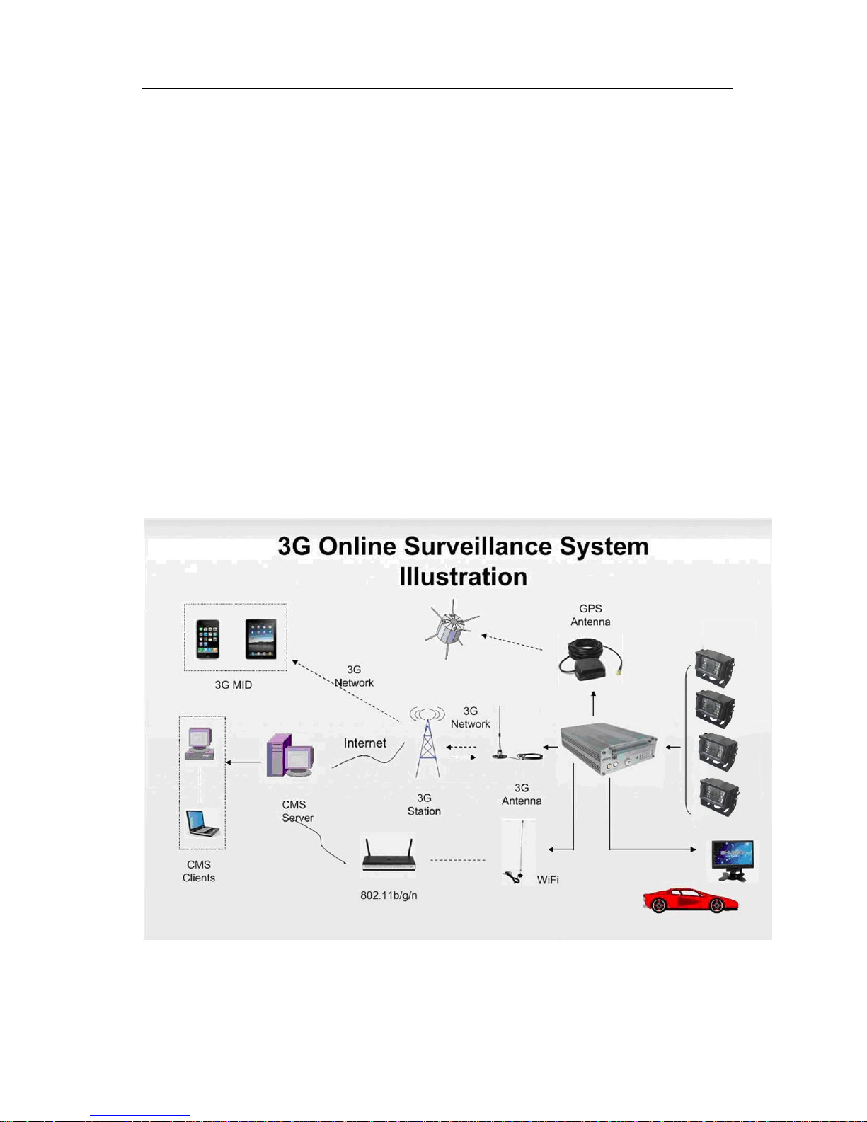
With the help of our CMS, this powerful MDVR can offer wireless live surveillance, Google map
online tracking, remote alarm, two-way voice communication and intelligence fleet management,
resume upload /download, video management, etc.
Features
H.264 video compression for high quality low storage needs and longer recording
D1 definition (720×576, NTSC, 704×576, PAL), QCIF/CIF/HD1 selectable.
4CH video and 4CH audio input, 1 video / audio output
Ultra compact extruded aluminum housing, light and vibration resistant
Embedded Linux operating system & On Screen Display menu
64G SDHC card at most( Class 4/ 6)
PC-based FAT 32 file system
Frame Rate per channel: (PAL) 1-25fps ; (NTSC) 1-30FPS
Live video & audio surveillance and tracking in Google Map
Support for 3G, GPRS & Wi-Fi for wireless transmission(optional)
4 alarm inputs with selectable pre-alarm and post-alarm recording
Interior, 3-axis, inertia trigger of video-matched motion events (for accidents)
Support for RFID, Police Detection Radar, Pan Tilt Zoom (PTZ), etc.
CMS support for video management, live tracking, large fleet management, etc.
Easy to use PC-based MDVR Player for playback and AVI output conversion
Video event search software allows intelligent searching of video based on event
8-48V DC input adaptive, 12 DC output for cameras
Broad temperature operating range: -40℃—60℃( optional heater)
Recommended Applications:
Public Transportation, School Buses, Bank Vehicles, Police Vehicles, Military Patrol Vehicles,
Coaches, Commercial Tankers, Freight, Logistics Vehicles, etc.
Page 6
- 5 -
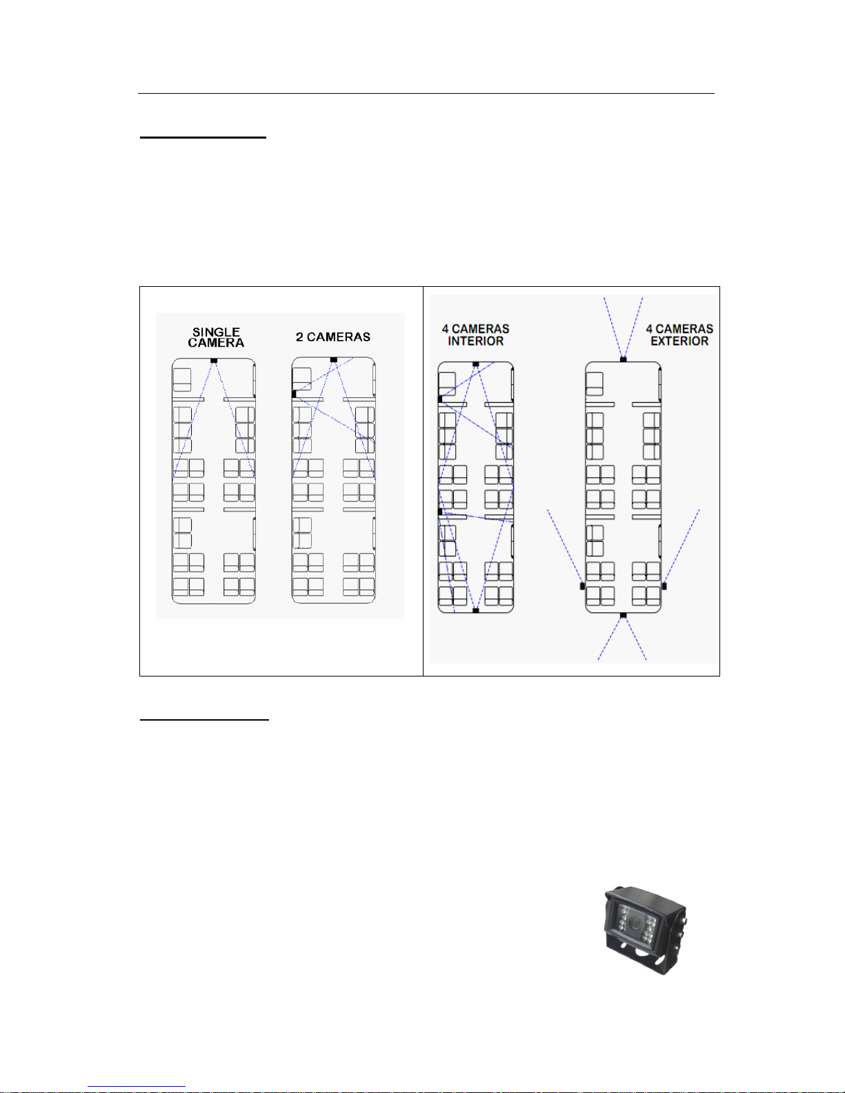
Camera Placement
Cameras can be mounted anywhere inside of the vehicle where a stable mounting platform is
available. Any selected location should be as vibration constrained as possible. For outdoor
applications, use outdoor cameras and observe the same low vibration recommendation.
Recommend placement illustrations of in vehicle cameras.
In-vehicle Cameras
Cameras for use in a vehicle are different from CCTV cameras. Below are some
recommendations:
A. For small vehicles, cars, taxis, trucks, or an SUV use a camera with 420TVL specifications.
For a bus, use 480TVL. For HD quality use 480TVL/540TVL to match with D1 resolution.
B. Mini metal (Aluminum) housings are recommended.
C. Outside of vehicle cameras need to have waterproof technology.
D. Illumination lamps should be available for night time applications.
E. Wide angel lens cameras are helpful in forward viewing situations.
Page 7

- 6 -
F. Vandal proof cameras should be used in criminal or rough environment applications.
Recording & Playback
System Start-Up
To start the recording process, place the system switch in the ON position (this will be
done automatically if the system switch is connected to the ignition switch and the ignition
switch is in the ON position). Upon turning the system switch ON, MDVR will commence
recording.
System Shut-Down
To stop the recording process, place the system switch in the OFF position. If the
Shutdown Delay option is enabled, the MDVR will continue to record for the prescribed
number of minutes. When the off-delay expires, the camera and MDVR will shut off.
Playback Options
1. TV Video Outputs (Front and Back)
Using a TV Monitor and the MDVR Remote Control, user can access recorded video files
by Date and Time or by Event. After selecting the appropriate file, the user can review the
video using Play, Stop, Pause, Fast Forward, Fast Rewind, Slow Forward, Slow Rewind,
Frame Forward, and Frame Reverse. The user can select individual video channels to be
displayed full screen by pressing the numeric button on the remote corresponding to that
channel, or view all channels at the same time.
2. Removable Hard Drive USB Connection
Using MDVR Player, user can access the files by connecting the computer to the
Removable Hard Drive Module Back Panel USB port.
3. Front Panel USB Connection
Using PC based MDVR Player, the user can copy videos to the USB flash disk or USB
DVD±RW equipments to access the files by connecting the computer to the DVR Front Panel
USB port.
4. PC Network Connection
It usually connects with 3G router to get a wireless communication, then user can
access the files through CMS (Central Management Software)
Page 8
- 7 -
MDVR Layout
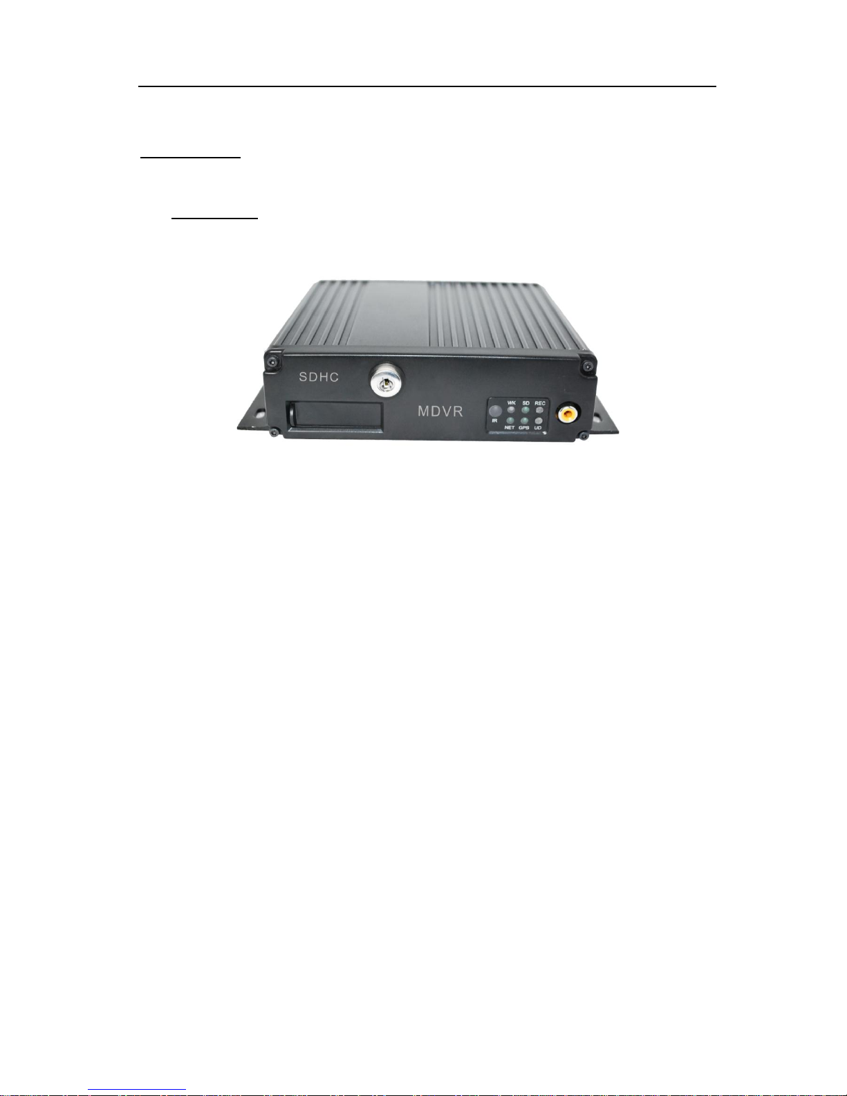
Front Panel
HDD Slot: the removable Hard Disk Drive occupies this slot in the MDVR. It is used to record
video images,
USB: For firmware update or backup with USB DVD±RW or USB Flash Disk
IR Indicator: Infrared receiver lens for use with the MDVR Remote Control unit. NOTE: Please
ensure that the MDVR is installed where the handheld IR controller can be pointed directly at
the IR receiver lens. Point your handheld controller at the spot on the recording module allowing
the unit to respond to commands from the controller.
LOCK: When you turn the key to the vertical lock position, the MDVR can start recording.
When you turn the key toward the horizontal unlock position, the MDVR will stop recording and
the HDD, with housing, can be removed from the MDVR.
Video: Video is standard RCA output
Audio: Audio is standard RCA output.
LED Indicator and Status Display:
[ WK ] Video recording and working status: LED ON indicates recording is on for at least one
channel.
[ HD ] LED ON indicates system is reading/writing to hard disk. OFF means no recording is
taking place or being written to storage media (HDD/SSD).
[ HT ] LED ON indicates the heater is working.
[ NW] LED ON indicates that 3G or Wi-Fi has connected successfully. OFF means no 3G/Wi-Fi
Page 9
- 8 -
signals are being received or launched, CMS can’t monitor the MDVR in this case.
[ CH1] ~ [ CH4 ] Video inputs : LED on indicates the camera is correctly connected.
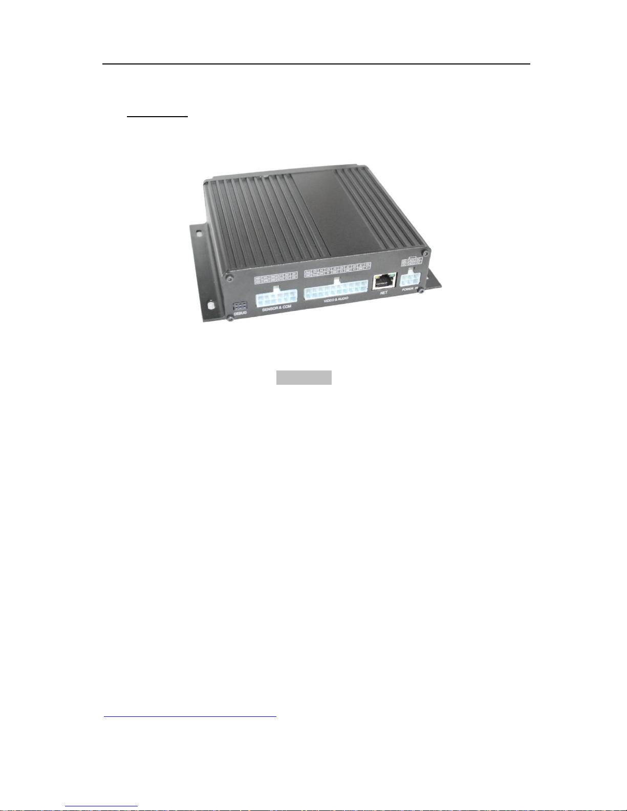
Back Panel
All connections to the MDVR are attached to the rear of the MDVR using pre-assembled cable
bundles specifically labeled for each purpose, It includes the following 6 parts:
GPS: Connects to the GPS antenna - if you order the MDVR with GPS.
WIFI/3G: Connects 3G/Wi-Fi antennas to facilitate a good signal.
AV: audio and video input interface with power output for cameras
I/O: Sensors and RS232/485 communication connection (RFID, sensors, etc.)
NET: Network Connection port (RJ-45)
POWER IN: Power Connections
DEBUG: Use by manufacturing to check for any problems before delivery
Disconnecting a cable bridal does not affect the operation of remaining MDVR functions
Note: The 3G slot is in the bottom of MDVR.
Back Panel
Page 10
- 9 -
Installation
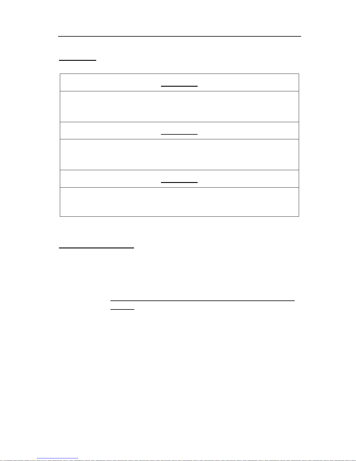
WARNING
DISCONNECT VEHICLE BATTERY VOLTAGE BEFORE INSTALLING
SYSTEM WIRING
WARNING
DISCONNECT POWER TO MDVR BEFORE JUMP
STARTING VEHICLE
WARNING
INSTALL DVR HORIZONTALL Y. USE EXTERNAL SHOCK ANDVIBRATION
DAMPENING IF NEEDED
Proper Mounting Location
For proper installation of the MDVR, choose a location in the vehicle that meets the following:
Power:
It is recommended that the MDVR be connected to the vehicle ignition.
Battery power is used only when the vehicle is running.
NOTE: The MDVR could drain any vehicle battery over time if the ignition is not
turned off.
Connection:
Connect only to appropriate power supply and ensure proper grounding of
the circuit. Use crimp-on connections where possible.
Moisture:
Protect unit and connections from environmental sources of moisture and
liquid spills.
Temp:
Do not install where unit temperature will exceed F140°F (60°C) or fall below
-20°F (-28°C) or store the unit where temperatures rise above 175°F (80°C).
Avoid direct exposure to sunlight.
Ventilation
Provide sufficient ventilation with a minimum of 6 inches cooling clearance to
ensure proper operating temperature for the unit.
Page 11

- 10 -
Vibration:
If necessary, provide additional shock mounting to prevent damage and wear
by excessive vibration.
Clearance:
Front clearance of 8 inch is required to slide the recording module from the
mounting assembly.
Wiring:
Install where mounting assembly wires have sufficient clearance and will not
be crimped or subject to wire insulation damages due to vibration.
Access:
Secure the MDVR so that passengers or drivers cannot tamper or damage
the unit, cameras, wires or other accessories. Do not mount where access to
any other vehicle component will be restricted.
Injury:
Install the unit, cameras, accessories and wires so that no injuries can be
caused through impact with equipment during vehicle operation. Ensure that
all transportation regulations are followed to avoid passenger injury should
they come in contact with the installed
Installation Instructions
Follow these guidelines when installing the MDVR:
Remove all components provided in the package.
Disconnect any power supply or device.
Locate a proper spot to install the mounting assembly and provide any additional shock
absorption if necessary. Locate a reliable electrical ground point in the vehicle.
Make all connections to the rear of the mounting assembly.
Connect power source and turn the vehicle ignition (make sure this connects with ―Signal‖)
to test the unit.
Observe completion of the unit power-up procedures as described in section labeled
―System Startup and Shutdown‖.
Maintain any labeling information required by local or state statutes for video surveillance.
Page 12
- 11 -
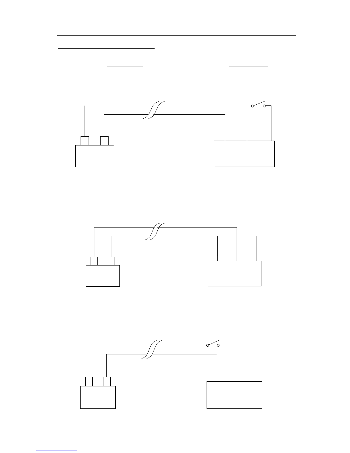
MDVR System Power Connection
Ignition Mode: Recommend! Ignition mode allows MDVR to be Power On or Off as long as
you ignite or shutdown vehicle. You also need setup startup recording mode in
Record >>Genera as show in Page 21, then decide when the MDVR start recording.
Timer Mode: Timer Mode allow MDVR be Power On or Off following the starting time and
shutdown time you set in MDVR startup mode in Genera>>Vehicle as show in Page 31.
Then select the startup recording mode in Record>>General as shown in Page 21.
Standby Mode: This mode allows MDVR keep Power On all the time only if vehicle battery
can off enough power. Then select the startup recording mode in Record>>General as
shown in Page 21.
Battery
+
-
DC-
Black Cable
DC+
Red Cable
MDVR
Battery
+
-
MDVR
Ignition
.
ACC
Yellow Cable
DC+
Red Cable
DC-
Black Cable
Battery
+
-
MDVR
Ignition
DC-
Black Cable
DC+
Red Cable
ACC
Yellow Cable
ACC
Yellow Cable
Page 13
- 12 -
IR Remote Instructions
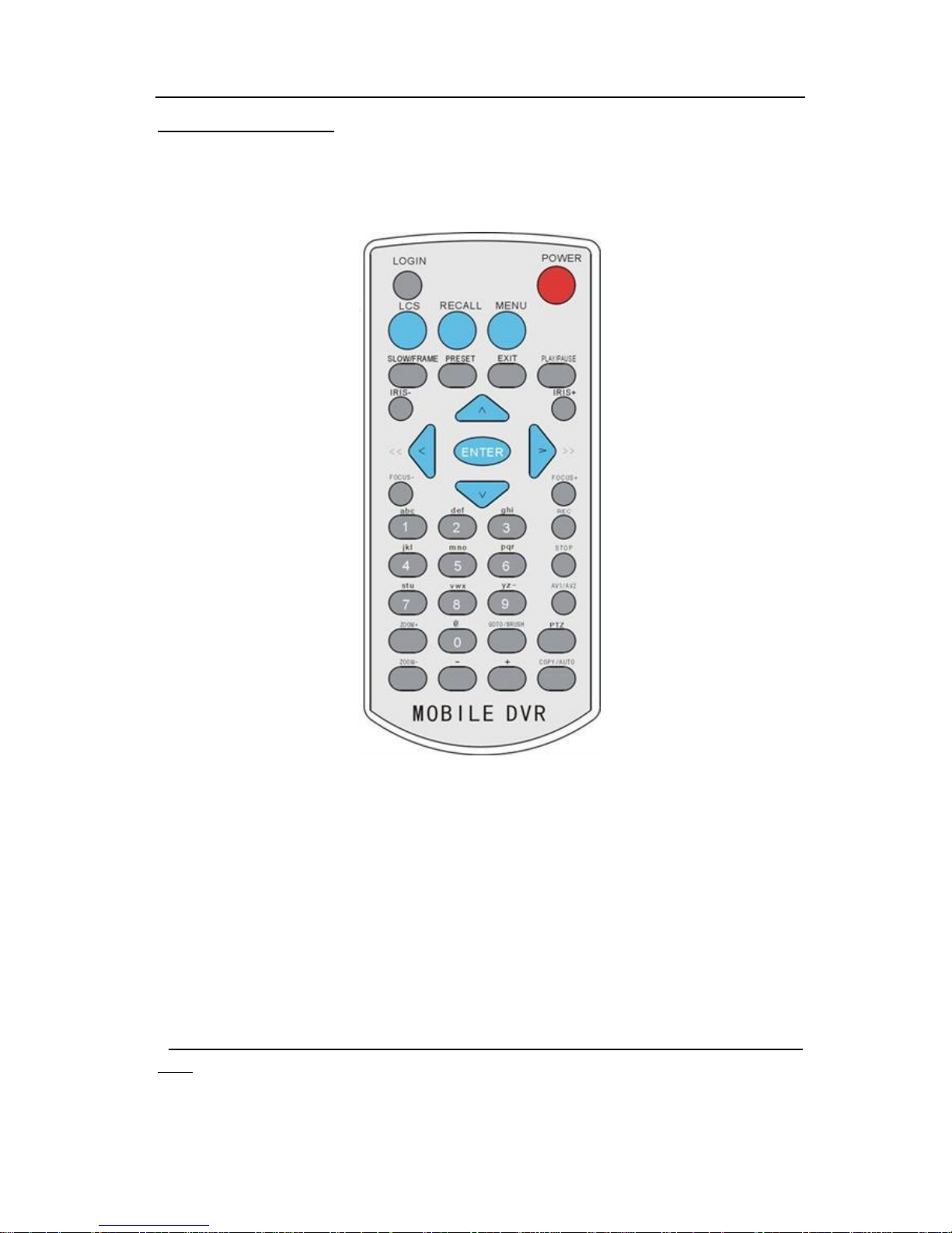
Each MDVR includes a handheld Infra-Red (IR) controller that allows the user to transmit commands
to the recording module and display on a screen control menu on a composite monitor (V1 output).
Numeric Input Keys
Use the numbers to input values in the system setup screen or switch through the channels in live
and playback. Plus and Minus is used to increase setup values one by one.
Navigation Cursors
Use the CURSOR keys to move between selections, input fields and icons. Press ENTER to select
and EXIT to cancel and return main menu. Next and previous is also used to increase or decrease
volumes when viewing live or search screens.
* Note: The Up key can delete the input character or number in case of driver information and security
setup.
Page 14

- 13 -
Other Important Keys:
Regular Keys
LOGIN
Press Login key to enter the main menu, enter user ID and password to
start setup
Enter
Select, Enter, Confirm
Shift ABC/abc /123 input
EXIT
Cancel and exit
POWER
The Power button can reset the DVR into sleep mode (unit will stop
recording while in the sleep mode)
PRESET
Preset
PLAY/PAUSE
Starts/Resumes playback from any other mode (FF, RR, Frame by
Frame etc)
-
Audio volume down
+
Audio volume up
Below are keys used only for Pan Tilt Zoom camera functions
PTZ
Start to active the PTZ function
RECALL
PTZ Mode
IRIS-
Decrease Iris
IRIS+
Increase Iris
FOCUS-
Focus in
FOCUS+
Focus out
Zoom-
Zoom out(only PTZ)
Zoom+
Zoom in (only PTZ)
Page 15
- 14 -
Menu Configuration
Login Page
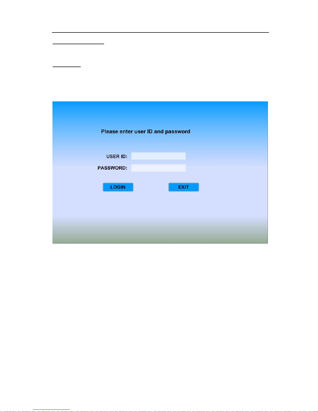
Press LOGIN on IR Remote to enter "LOGIN" interface. Enter your registered ID and password,
then Select 【LOG IN】to enter main menu.
Note: In order to protect privacy, users should always have a user ID and password. The default
MDVR setting is no User ID and password.
FOR SECURITY REASONS, please setup a User ID and Password for every MDVR as soon as
possible (installation time is best).
NOTE: Administrators and Clients have login rights, but Administrators can create and delete client
ID’s.
Page 16
- 15 -
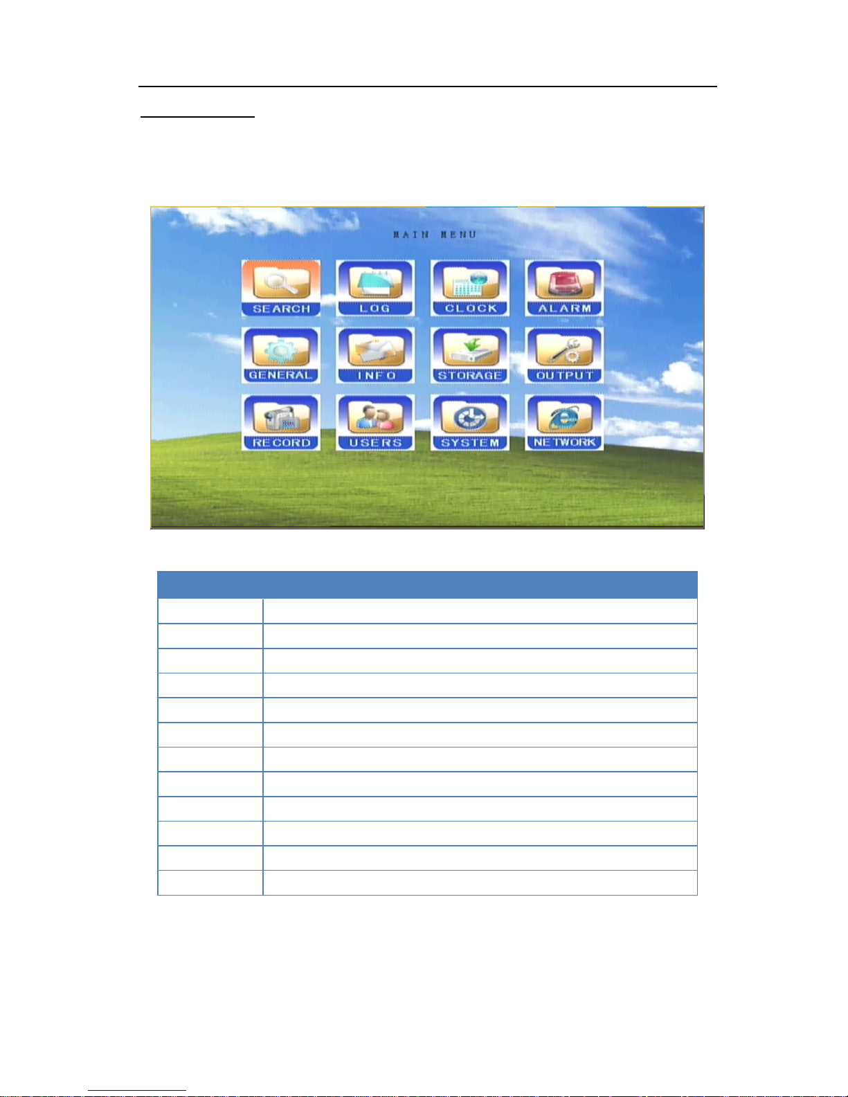
Main Menu Page
Select any sub-menu you want by position the Cursor over the sub-menu item and press【ENTER】
on remote controller to start the setup process.
Menu Guide
SEARCH
Search Recordings
LOG
Event Logs
CLOCK
Adjust date and time
ALARM
I/O Sensors / G-sensor/ Speed alarm input and output
GENERAL
Vehicle /Driver /Inserted Info
INFO
Modules/ History information
STORAGE
SD/HDD space status/Format
OUTPUT
PTZ Protocols
RECORD
General options/Setup/Schedule
USERS
ID and Password Management
SYSTEM
Update/ Restore system
NETWORK
Network Protocols Properties
Page 17
- 16 -
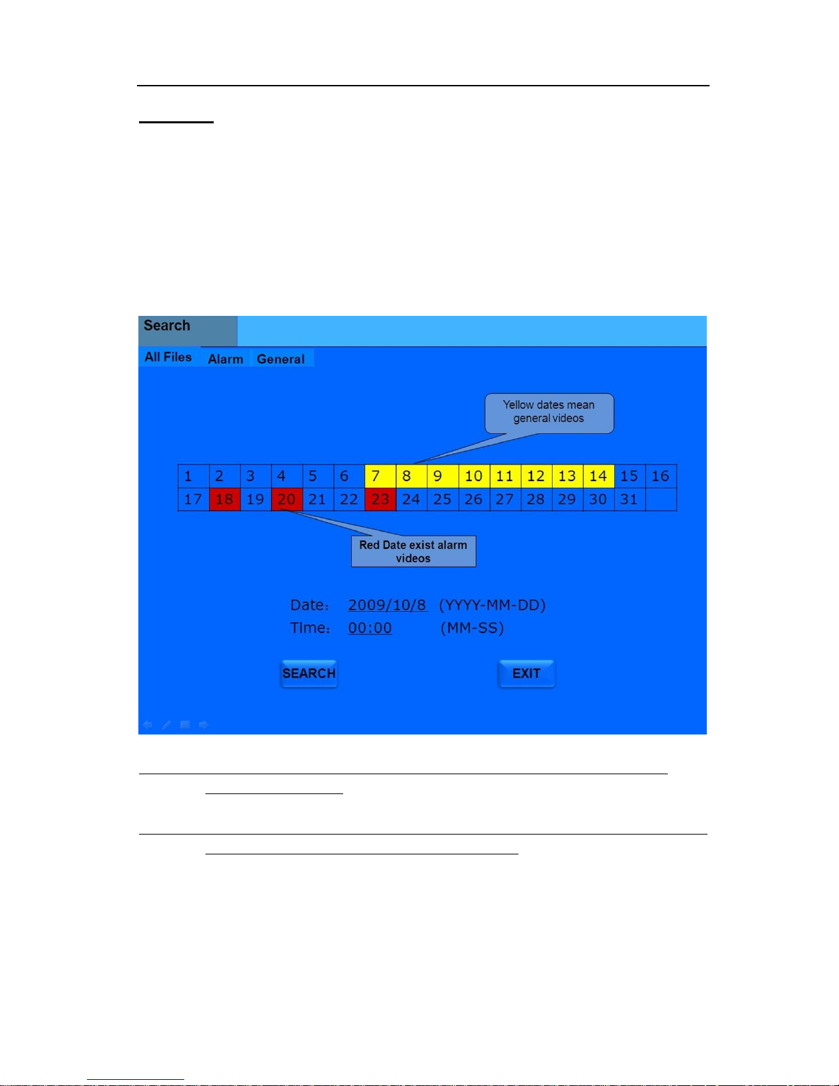
SEARCH
To search for and playback any video currently on MDVR. The files are selectable (using the
arrow buttons, the numeric buttons, and the 【ENTER】 on the remote control) by entering in a date
(and optionally a time) of the recorded files.
Option:
Select "SEARCH" icon with remote controller and press【ENTER】. GUI appear like below:
NOTE 1: The MDVR always records based upon the RECORD MODE settings, even when
playing back video files.
NOTE 2: Please notice the color of the date. Both yellow and red mean that a recording exists. A
blank date means that no recording exists for that date.
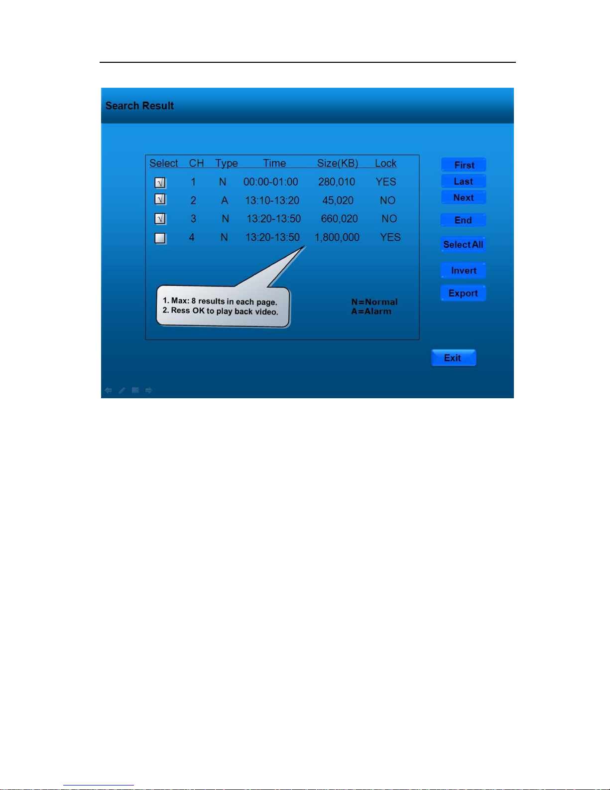
Search Result
In the search result list, the information about a recording, including Camera, type, time, and size are
shown:
Page 18
- 17 -
P.18
After the correct date has been chosen, a list of files appears for video file selection. The size
of the video file is determined by the RECORD FILE SIZE, as shown in P.18
Use the arrow buttons and the 【ENTER】 key on the remote control to select and activate a
video file to playback. The MDR always records based upon the Startup Mode settings, even when
playback video files.
Page 19
- 18 -
LOG
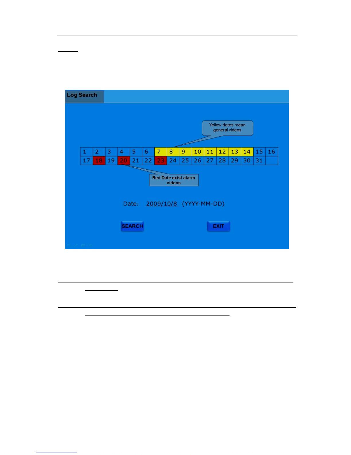
The MDVR maintains a log file of activities and events.
Select "LOG" icon with remote controller and press【ENTER】. GUI appear like below:
NOTE 1: The MDVR always records based upon the Startup Mode settings, even when playing
back log files.
NOTE 2: Please notice the color of the date. Both yellow and red mean that a log file exists. A
blank date means that no log file is available for that date.
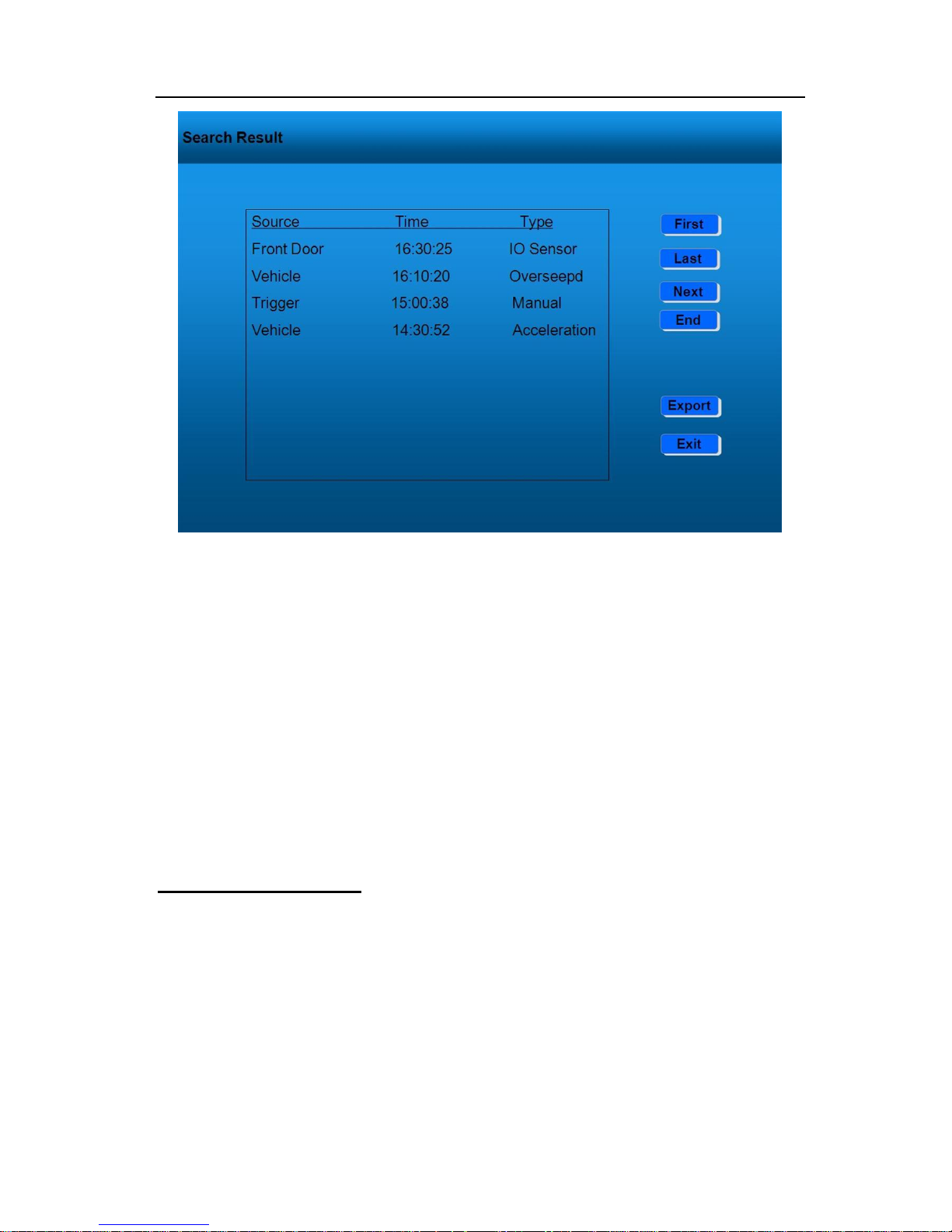
Search Result
In the search result list, you can see information about a log file, including Source, Time, and Type
of entry.
Page 20
- 19 -
Source: press【ENTER】 key on remote controller to select the type of Event;
Time: To check the time of the video files, use the number keys to input;
Type: You can see the information type.
PAGE UP /PAGE DOWN: If results are more than one pages.
Press【EXIT】 icon on GUI to return to previous menu.
CLOCK (Date&Time):
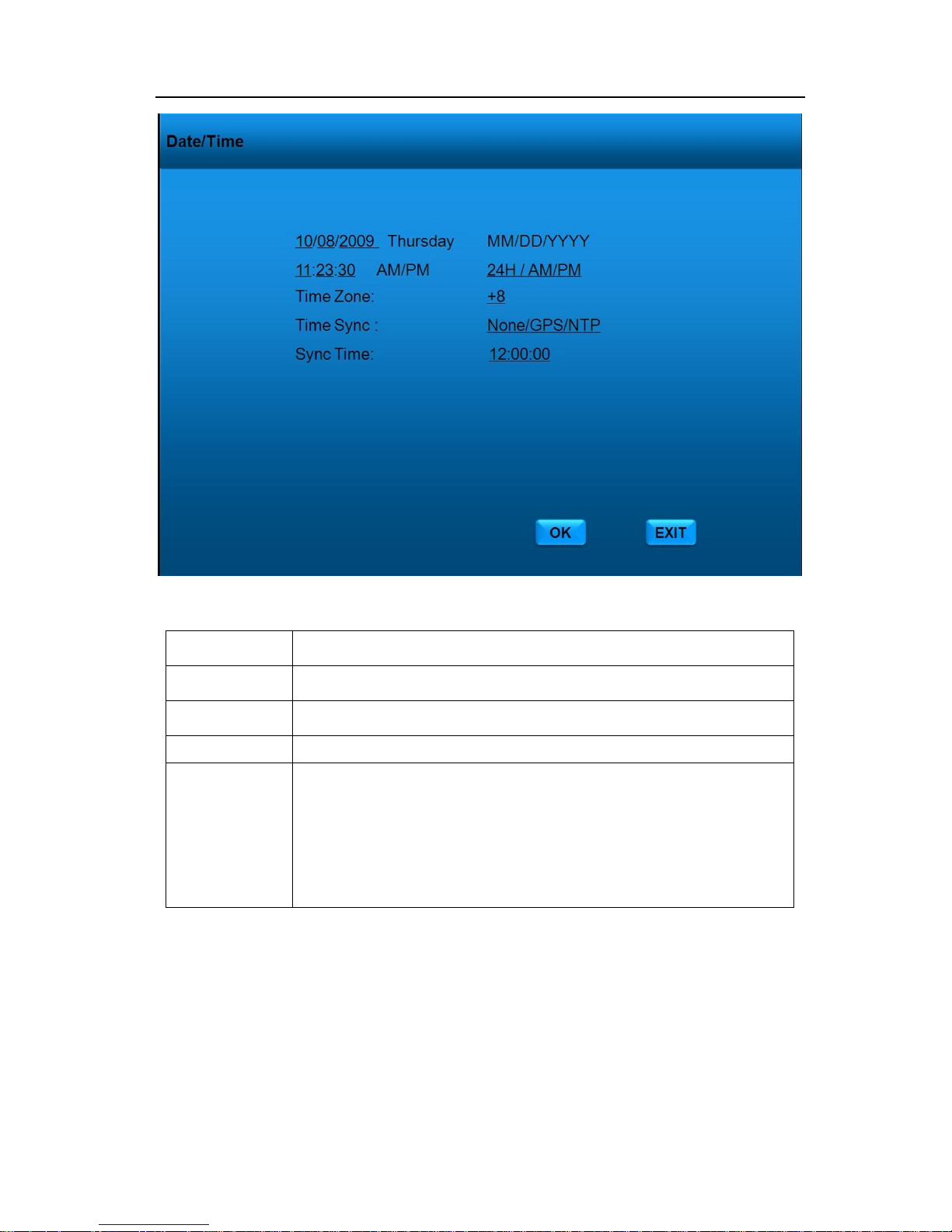
Select "CLOCK" icon with remote controller and press【ENTER】. GUI appear like below:
Page 21
- 20 -
Date:
MM/DD/YYYY Enter with number keys
Time:
HH/MM/SS Enter with number keys
Time Zone
Select your local time zone (GMT+/-12)
Sync Time:
This is the time when the unit will sync the system time every day.
Time Sync :
i. When selecting the “GPS” option, the device must have a GPS
connection and the GPS signal must be strong.
ii. When selecting the “NTP‖ (Network Time Protocol) option, the device
must have a network access connection and the NTP IP location must
be a valid assignment.
Iii. NONE (Default)
Select【OK】on the GUI and press 【ENTER】on remote controlller to save changes. Press 【EXIT】
on the GUI or remote controller to return Main Menu without any change.
Page 22
- 21 -
ALARM
Select "ALARM" icon with remote controller and press【ENTER】to show alarm setup GUI.
There are 3 type of sensors: I/O, G-sensor and Speed.
I/O
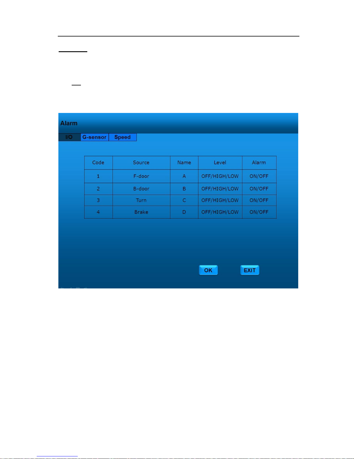
The MDVR supports 4 separate sensors input for normal alarm signal receiving.
Select I/O page, and press 【ENTER】button on remote controller and show GUI like below:
Source: The name of the signal connected to the MDVR. The names of the signals should
be filled by remote controller and are limited to 8 characters.
Name: The characters that are displayed on the Installers Mode Page. The displayed
characters of the signals should be filled by remote controller, and are limited to 2
characters.
Level: To indicate if active at HIGH voltage, LOW voltage, or OFF. The sensors’ voltage is
higher than 8V means HIGH,lower than 5V means LOW, 0V means OFF. Please
don’t put the input voltage between 5V and 8V, that makes MDVR confusing.
Alarm: To indicate if the sensor is turn ON or OFF
Select 【OK】on the GUI and press 【ENTER】on remote controller to save alarm information. Press
【EXIT】on the GUI or remote controller to return Main Menu without any change.
Page 23
- 22 -
G-Sensor
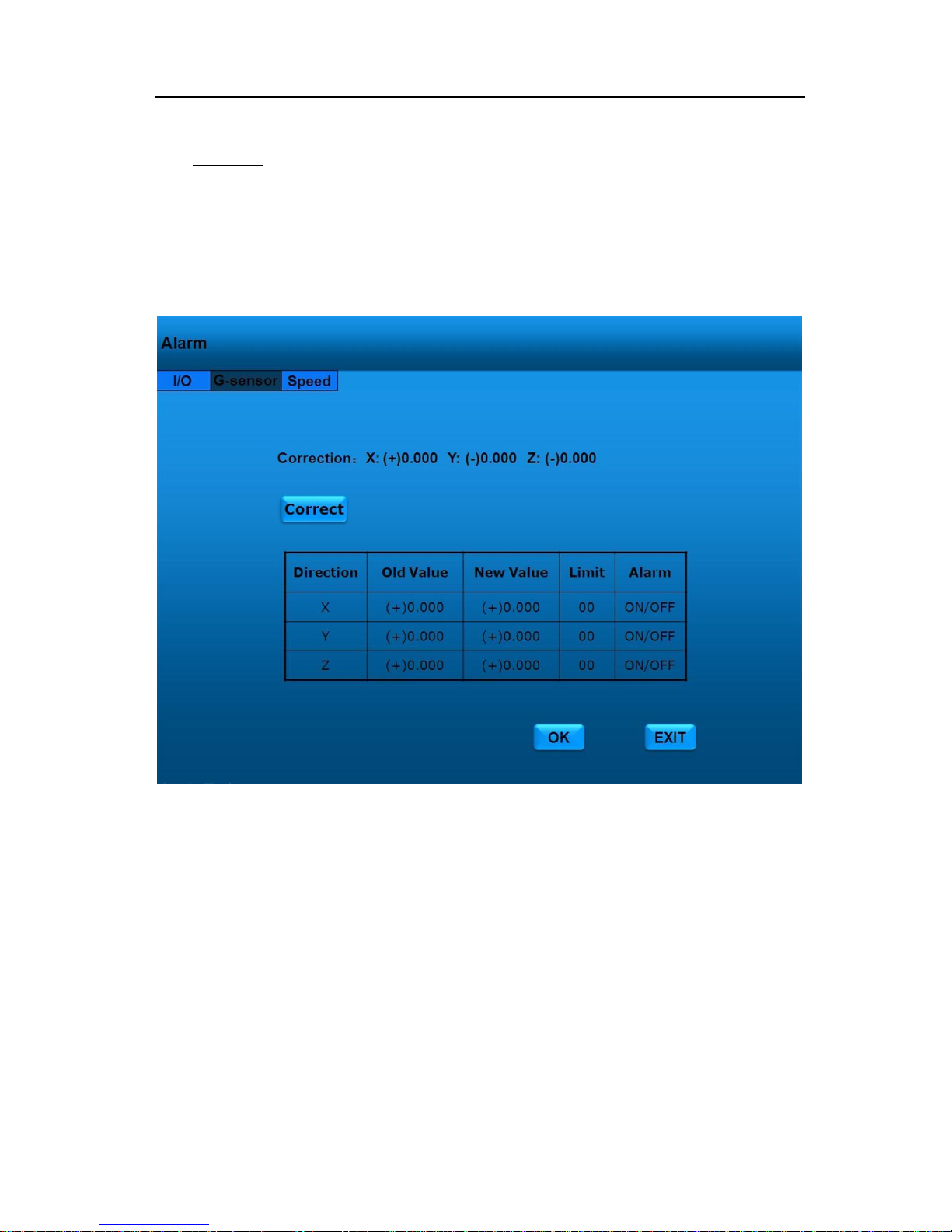
The G-sensor subsection of the SENSOR section, also called accelerometer, is used to
calibrate the accelerometer readings coming out of the accelerometer/ inertia sensor harness.
Select G-Sensor page, and press 【ENTER】button on remote controller and show GUI like
below:
Because of the varying nature of the installation options, users should go to this page and select
【Correct】 first, to zero out the readings on the display. This should be done when the vehicle is
stop and engine is not running. If properly installed, the accelerometer should read about 8 G at
most in the Z axis before calibration.
Select 【OK】on the GUI and press 【ENTER】on remote controller to save alarm information. Press
【EXIT】on the GUI or remote controller to return Main Menu without any change.
Page 24
- 23 -
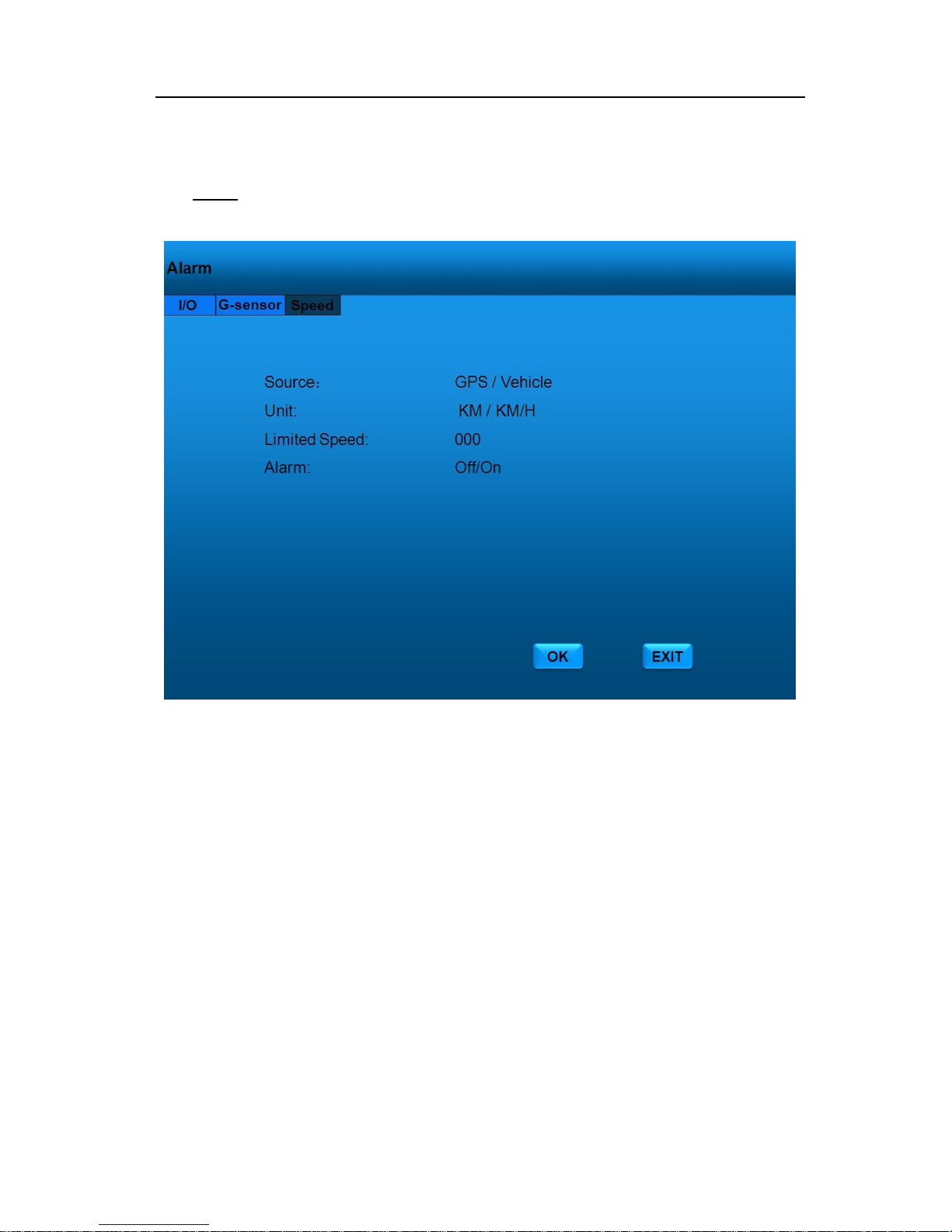
Speed
Select Speed page, and press 【ENTER】button on remote controller and show GUI like below:
Source: MDR is capable of capturing vehicle speed via GPS antenna or
Vehicle--speedometer. Browse between the settings of GPS or speedometer from the list.
Please note that the GPS antenna should be connected to MDR to receive satellite signals
for speed.
Unit: Kilometer per Hour or Mile per Hour
Limited Speed: If the vehicle exceeds the high speed limit, MDR will trigger the alarm
signal (when the following option ALARM set as YES) until the Admin password is entered
to acknowledge the alarm.;
Alarm: Press【ENTER】to select ON/OFF, yes means when some directory’ s sample value
over it’s limited, alarm LED will flashing, until re-login the system with account ,the flashing
will disappear, also, if the security set as no, I.E no need enter password to re-login, just
pressing 【ENTER】 can disappear the flashing
Select 【OK】on the GUI and press 【ENTER】on remote controller to save alarm information. Press
【EXIT】on the GUI or remote controller to return Main Menu without any change.
Page 25
- 24 -
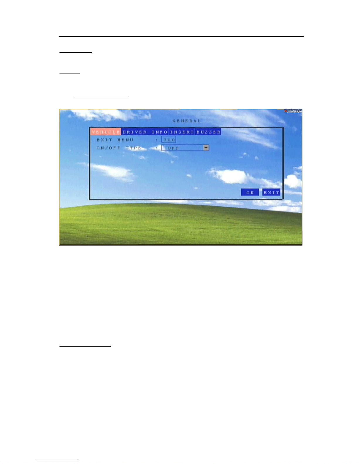
GENRAL
Vehicle
Select Vehicle from the General Menu and press【ENTER】 at the highlighted line.
Normal Startup Mode
Indications.
Exit Menu :
Menu will exit automatically after gaven seconds without any selection
ON/OFF TYPE:
OFF means no effect.
Select 【OK】on the GUI and press 【ENTER】on remote controller to save alarm information. Press
【EXIT】on the GUI or remote controller to return Main Menu without any change.
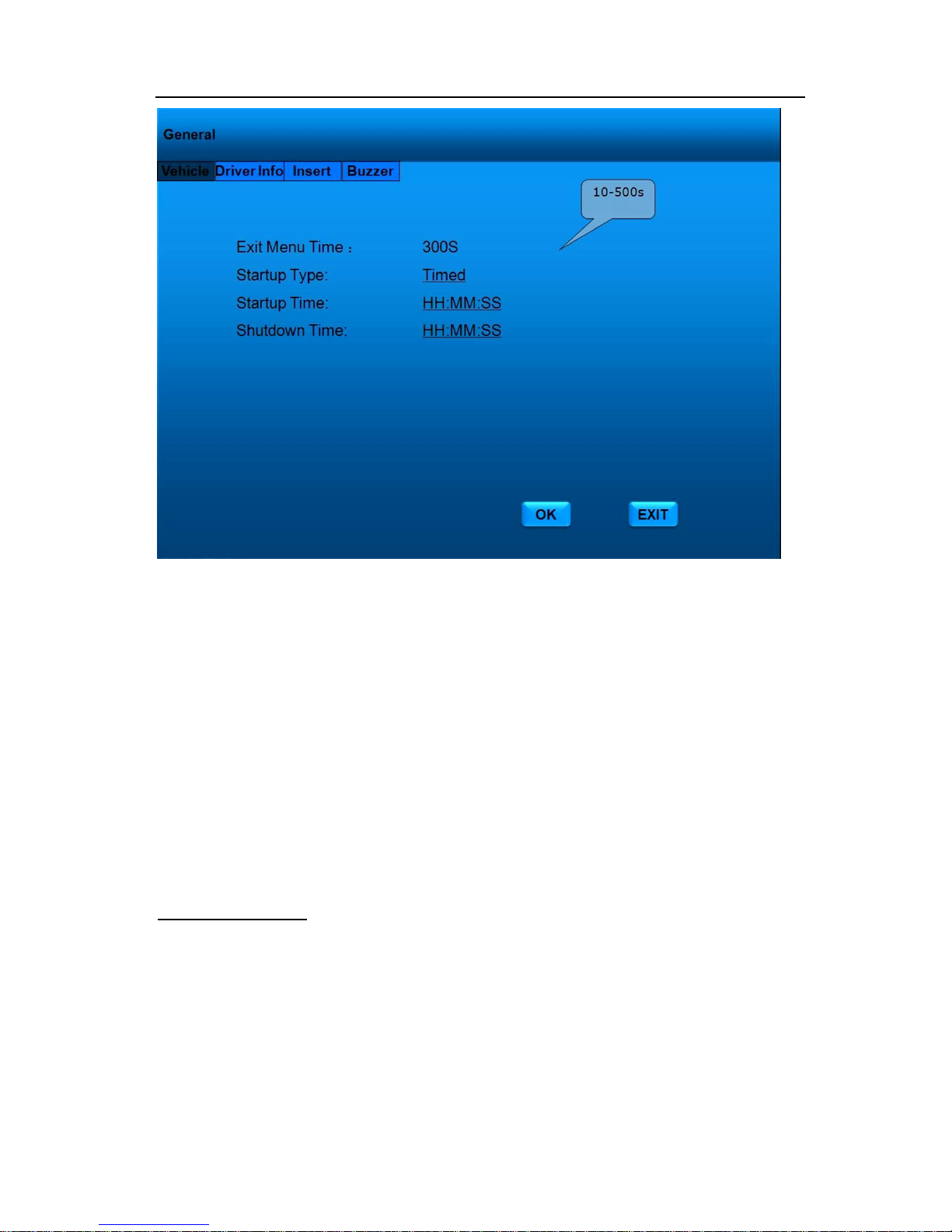
Timer Startup Mode
Page 26
- 25 -
Indications.
Exit Menu Time:
Menu will exit automatically after 300 seconds without any selection
Startup Type:
Select Timed
Startup Time
Set time when the MDVR start to work.
Shutdown Time:
Set when the MDVR shut down.
Select 【OK】on the GUI and press 【ENTER】on remote controller to save alarm information. Press
【EXIT】on the GUI or remote controller to return Main Menu without any change.
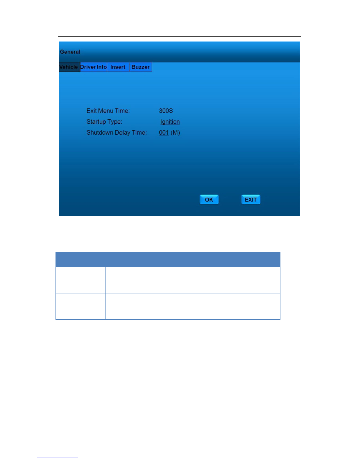
Ignition Startup Mode
Page 27
- 26 -
Indications
Exit Menu Time:
Menu will exit automatically after 300 seconds without any selection
Startup Type:
Select Ignition
Shutdown Delay
Time
Set the MDVR shutdown delay time from 0 to 300 minutes.
Select 【OK】on the GUI and press 【ENTER】on remote controller to save alarm information. Press
【EXIT】on the GUI or remote controller to return Main Menu without any change.
DriverInfo
Page 28
- 27 -
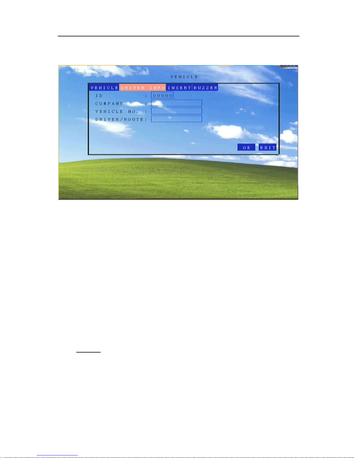
Vehicle is used to store the following text information into the unit: Company Name, Vehicle No.
and Driver /Route Name. Select DRIVER INFO page.
Select 【OK】on the GUI and press 【ENTER】on remote controller to save alarm information. Press
【EXIT】on the GUI or remote controller to return Main Menu without any change.
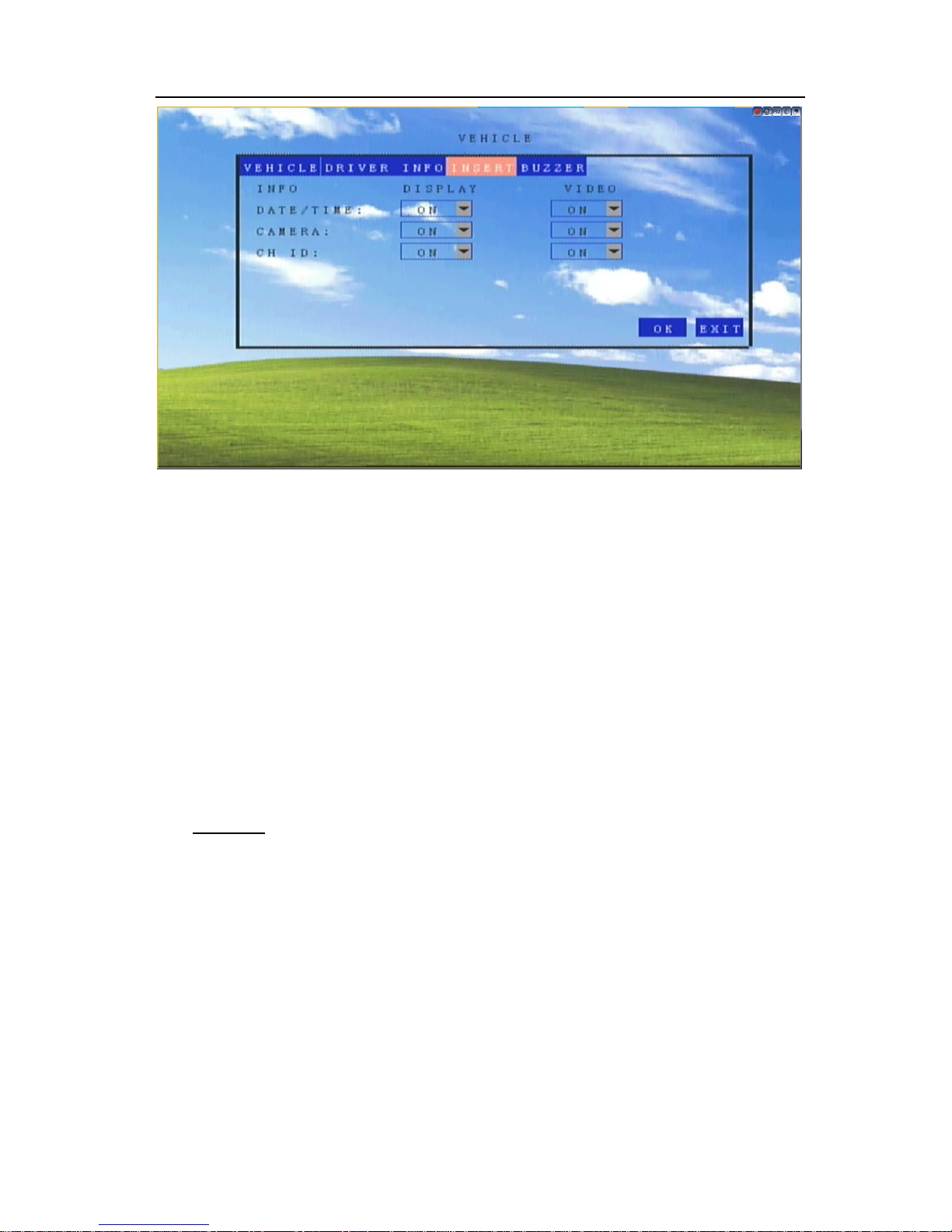
INSERT
This feature allows you to display the Date/Time on a monitor attached to the MDVR and/or
on the recorded video. In like manner, you can do the same with Camera information.
Use CURSOR keys to select Insert menu to decide whether display Date/Time and Cameras
Name will appear on the monitor and in recorded videos. Press 【ENTER】 at the highlighted line.
Page 29
- 28 -
Select 【OK】on the GUI and press 【ENTER】on remote controller to save alarm information. Press
【EXIT】on the GUI or remote controller to return Main Menu without any change.
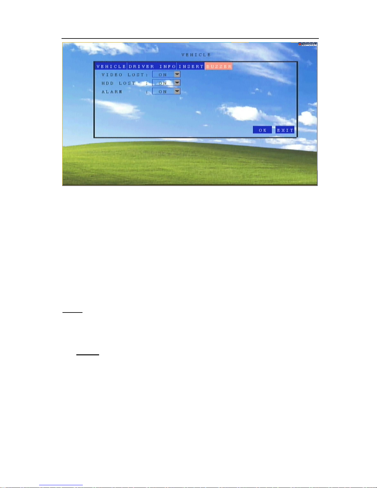
BUZZER
The MDVR can alert when due to video recording errors, recording media problems and sensor
alarms.
Select BUZZER page for modification. Press 【ENTER】on remote controller the highlighted
line.
Page 30
- 29 -
Video Lost: ―On‖ will trigger the buzzer alarm when videos are lost.
HDD Lost: ―On‖ will trigger the buzzer alarm when HDD read or write errors occur
Alarm: ―On‖ will trigger the buzzer when attached sensors are tripped
Select 【OK】on the GUI and press 【ENTER】on remote controller to save alarm information. Press
【EXIT】on the GUI or remote controller to return Main Menu without any change.
INFO
Your MDVR will provide a status of its communications module(s) – working or not working.
Module
Press 【ENTER】 Key Select INFO>> Modules section with remote controller. Here you can
check what the modules working status.
Page 31
- 30 -
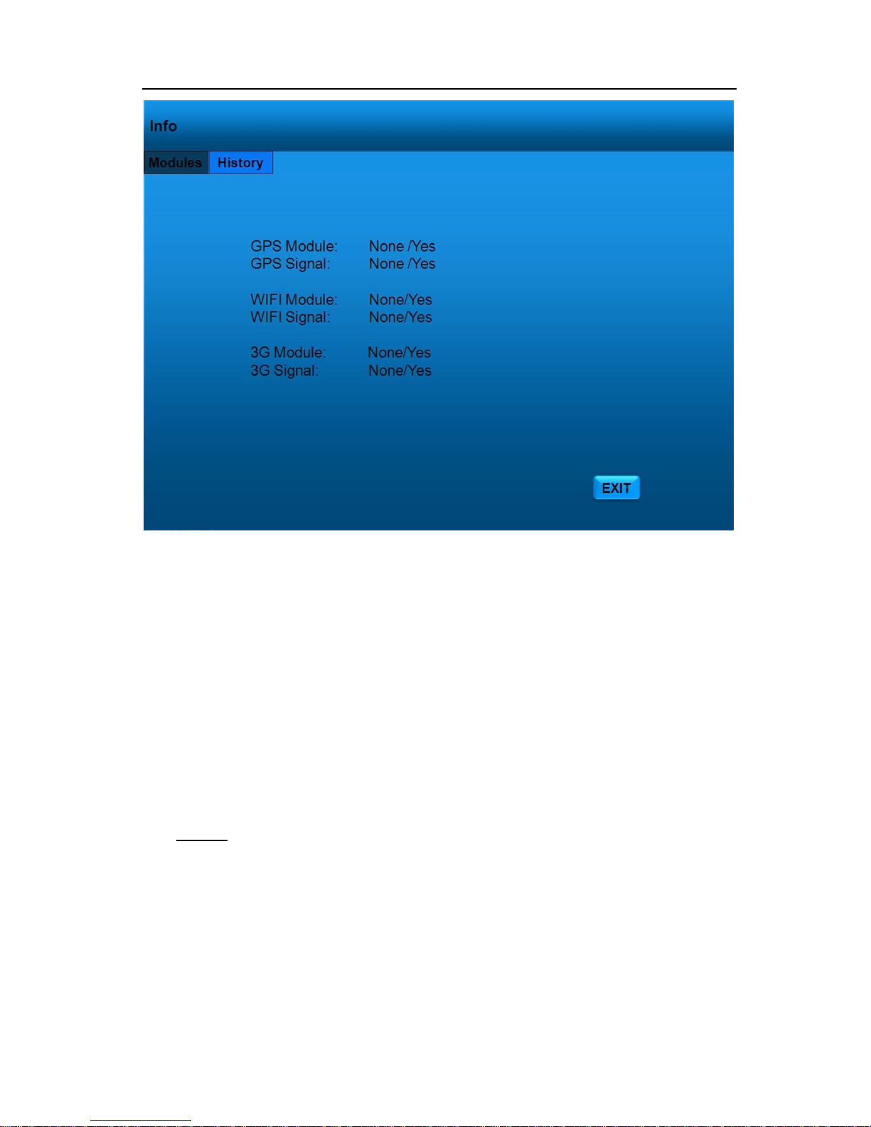
This section show you whether modules is working well.
GPS Module
MDVR should be associated with GPS module and antenna
GPS Signal
GPS signal is good, you will see Yes.
WIFI Module
MDVR should be associated with WIFI module and antenna
WIFI signal
WIFI signal is good you can see Yes.
3G Module
MDVR should be associated with 3G module and antenna
3G Signal
3G signal is good, you can see Yes.
Press【EXIT】 key to return to previous menu.
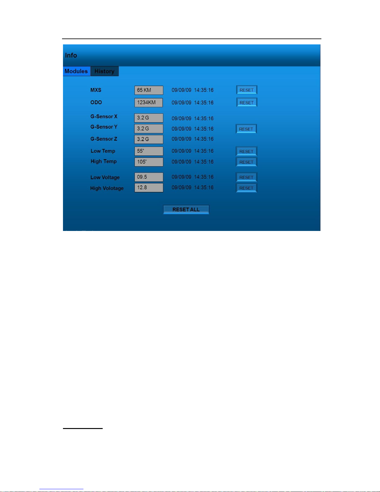
History
Select Info>>History, you can read the top important information of MDVR.
Page 32
- 31 -
MXS: The max vehicle speed record in the past.
ODO: The total ODO
G-Sensor: X/Y/Z record.
High Temp : The highest voltage of MDVR
Low Temp: The lowest voltage of MDVR
Low Voltage: The lowest voltage of MDVR
High Voltage: The highest voltage of MDVR
High speed (km/h): The maximum speed of vehicles;
Press 【RESET ALL】: Clear all system Log. Press【EXIT】 key to return to previous menu.
STORAGE
Page 33
- 32 -
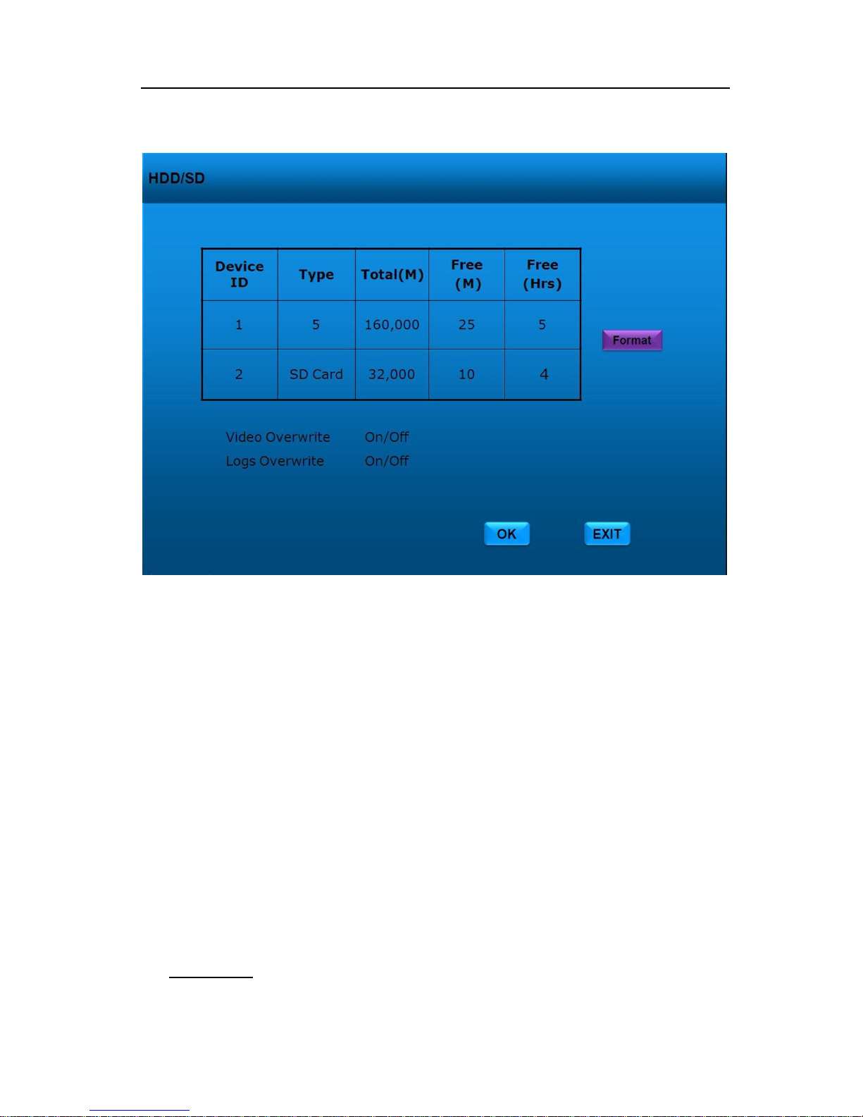
Use CURSOR keys to select HDD menu. Press【ENTER】to access input settings.
User can understand the HDD status at any time in this section.
HDD Overwrite
On: Will program the MDVR to automatically overwrite videos on the disk when it is full.
Off: Will program the MDVR to automatically stop recording and show a "Disk is Full" status.
Logs Overwrite
On: Will program the MDVR to automatically overwrite the disk log files when the disk is full.
Off: Will program the MDVR to automatically stop log file recording and show a "Disk is Full"
status.
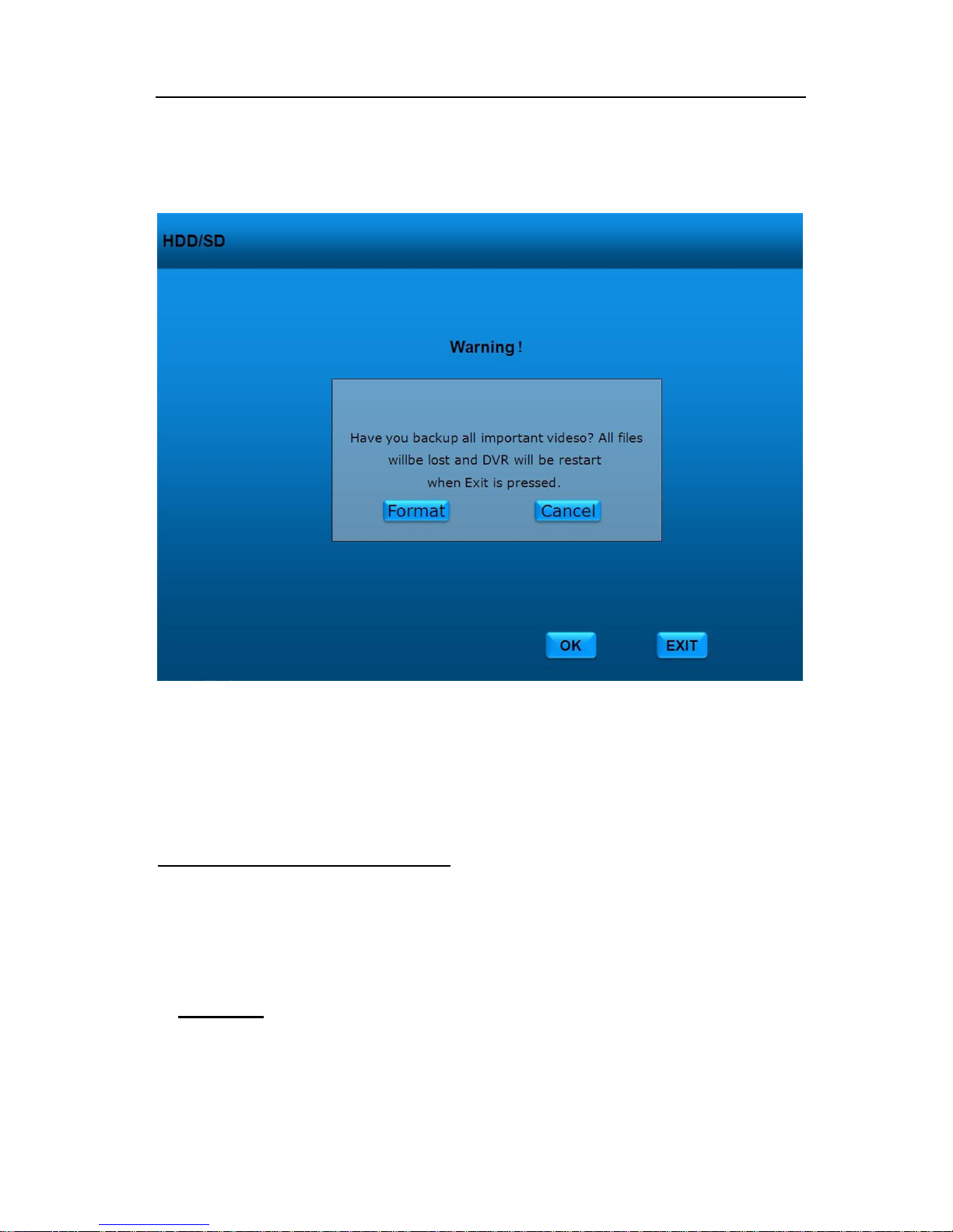
Disk Format
The user can completely erase the video and audio files off of the DVR. The HDD FORMAT
Page 34
- 33 -
function will rebuild the basic directory structure of the drive to allow for continued and immediate
recording of audio and video. All data will also be erased from the drive if this is executed.
When Format has been pressed, there is a confirmation required from the operator: Select
【Format】and press【ENTER】 to proceed with the hard disk formatting. 【EXIT】to cancel the
format operation.
Note: The MDVR will restart later after format.
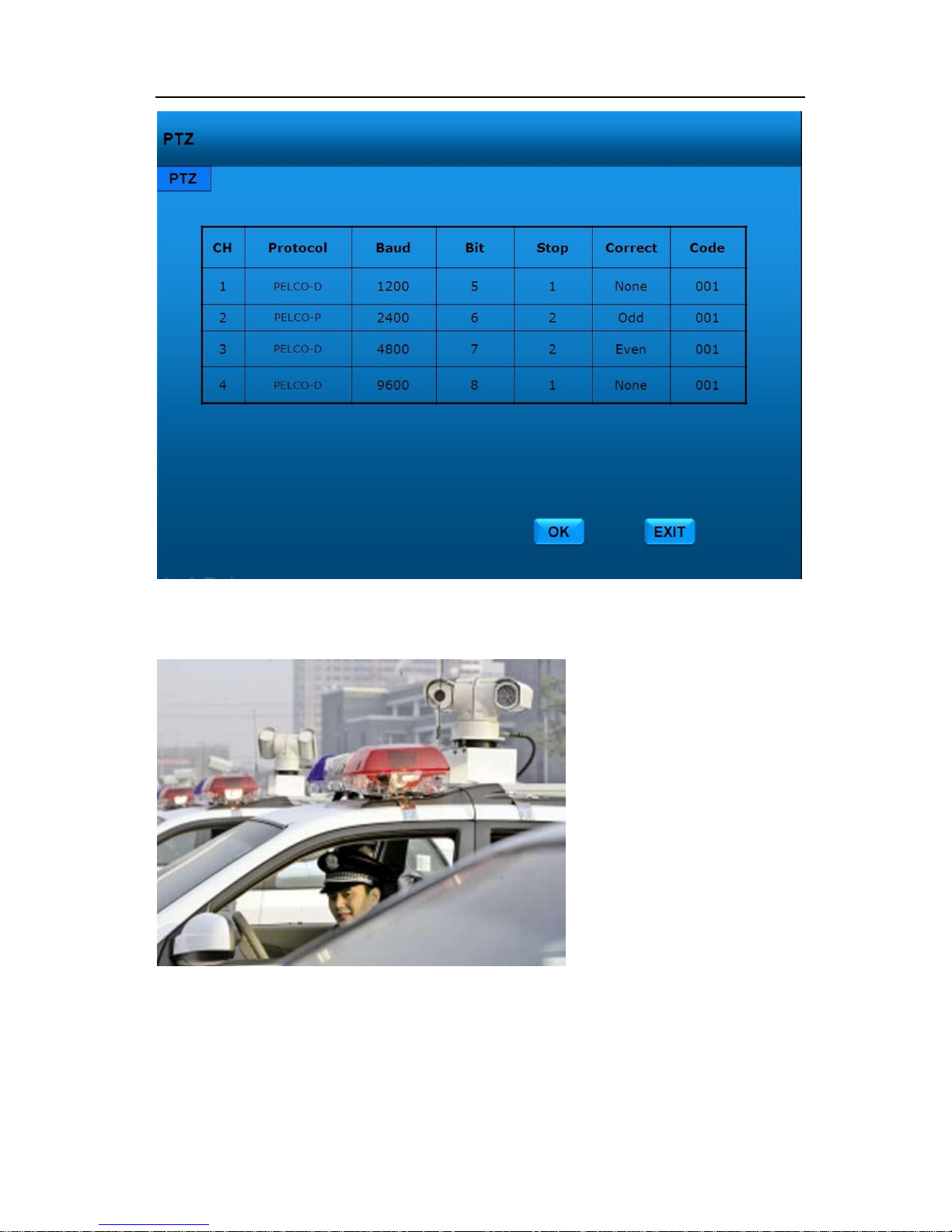
OUTPUT
If the MDVR will connect with PTZ or Speed Dome in some special vehicles, like police /military
patrol vehicles, you can set the PTZ protocols so that you can control the PTZ normally.
Page 35
- 34 -
Pan Tilt Zoom cameras are good
at 360 degree surveillance. With
the powerful optical zoom
camera, you can monitor miles
far away, even in the night.
Caution:
PTZ or Speed Dome is limited to
install in most countries. Installer
and users must promise your
camera never collect other’s
privacy.
Page 36
- 35 -
RECORD
General Options
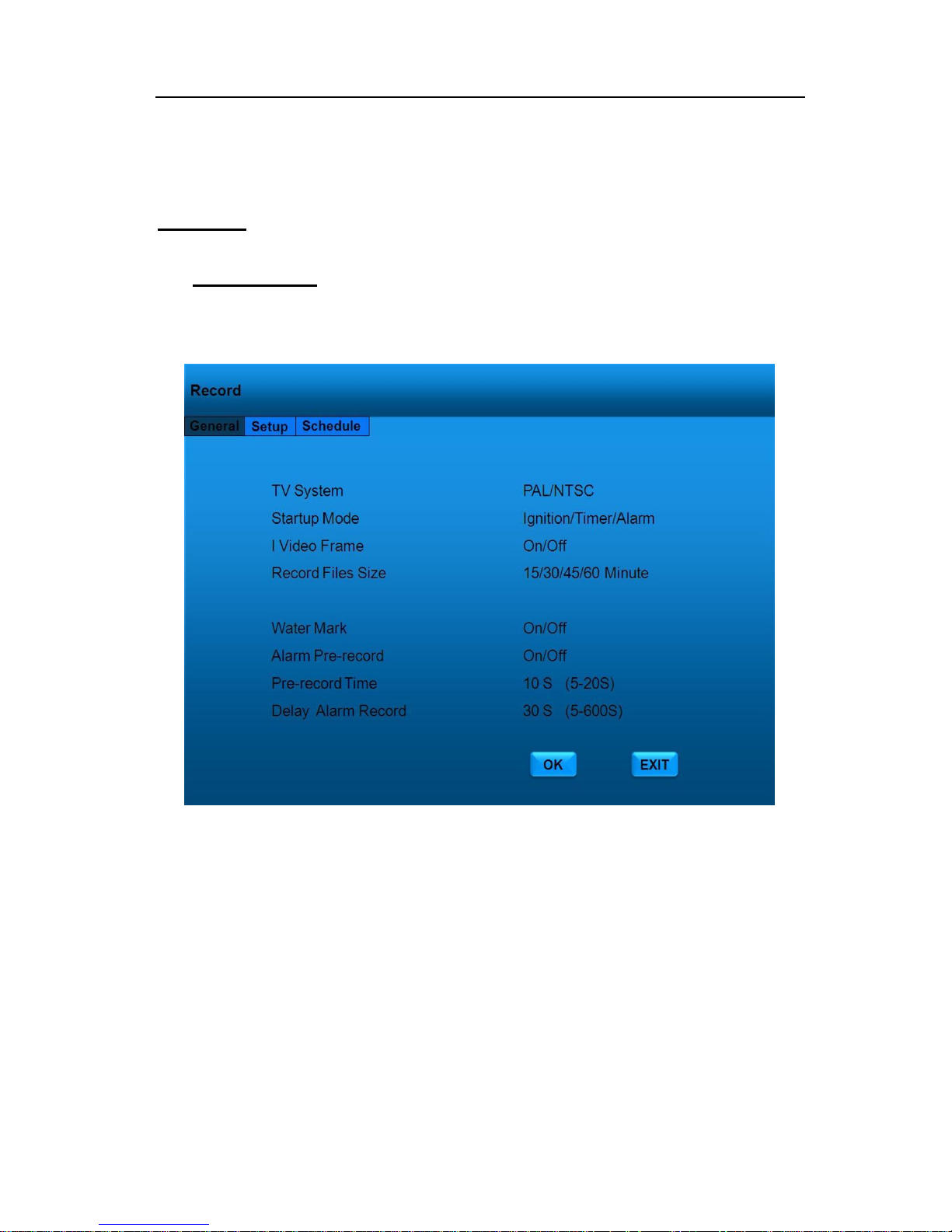
Use CURSOR to select RECORD and press【ENTER】to access the General section.
TV System: Select PAL or NTSC.
Startup Mode: Select the MDVR start recording mode.
I Video Frame: Default is Off (H.264 compression). If you select On, the compression
will change to M-JPEG mode, very clear but little compression.
Record Files Size: The record file size is used to break down the recording clips into
smaller time segments. The available selections are 15 /30/45/60 minutes.
Water Mark: Insert Date/Time information into videos.
Alarm Pre-record: Start to record before alarm/sensor is triggered.
Pre-record Time: The time (5-20S) to pre-record before alarm/sensor is triggered.
Delay Alarm Record: The time to record after alarm/sensor is triggered.
Select 【OK】 and press【ENTER】to save changes. Press【EXIT】to return Main Menu without
Page 37

- 36 -
any change.
Note: No wonder what MDVR Power Connection you select, Recording must be after Power On.
Record Mode Reference List
Power
Connection
Record
Mode
Start Record
End Record
Ignition
Ignition
When Ignition Switch towards
ACC, MDVR will start record at
once
When Ignition Switch towards
LOCK, MDVR will end record at
once
Timer
MDVR will start recording as
the definite time in P.24.
(The start time in schedule
must be later than ignition
time.)
MDVR will end recording as
the definite time in P.24
(The end time in schedule must
be later than time.)
Alarm
When Ignition Switch towards
ACC, MDVR will not record until
sensor/alarm is triggered in
P.41-P43.
If alarm Pre-record is ON in
P.21, you can get 5-25 seconds
record before alarm is triggered
each time.
MDVR will stop record after
5-600 Seconds of Delay Record
each time in P. 21.
When Ignition Switch towards
LOCK, MDVR will end record at
once
Timer
Ignition
MDVR will start recording as
the definite time in P.24
MDVR will end recording as
the definite time in P.24
Timer
If you need MDVR start
recording later than POWER
ON, you need setup a later
time in Record Schedule as
P.24
If you need MDVR end
recording earlier than POWER
OFF, you need setup a earlier
time in Record Schedule as
P.24
Alarm
MDVR will not record until
sensor/alarm is triggered in
P.41-P43. If alarm Pre-record is
ON in P21, you can get 5-25
seconds record before alarm is
triggered each time.
MDVR will stop record after
5-600 Seconds of Delay Record
each time in P. 21.
Turn you Ignition Switch towards
LOCK, MDVR will end record at
once
Standby
Timer
MDVR will start recording as
the definite time in P.24
MDVR will end recording as
the definite time in P.24
Alarm
MDVR will not record until
sensor/alarm is triggered in
P.41-P43. If alarm Pre-record is
MDVR will stop record after
5-600 Seconds of Delay Record
each time in P. 21. Turn you
Page 38
- 37 -
ON in P21, you can get 5-25
seconds record before alarm is
triggered each time.
Ignition Switch towards LOCK,
MDVR will end record at once
Camera Setup
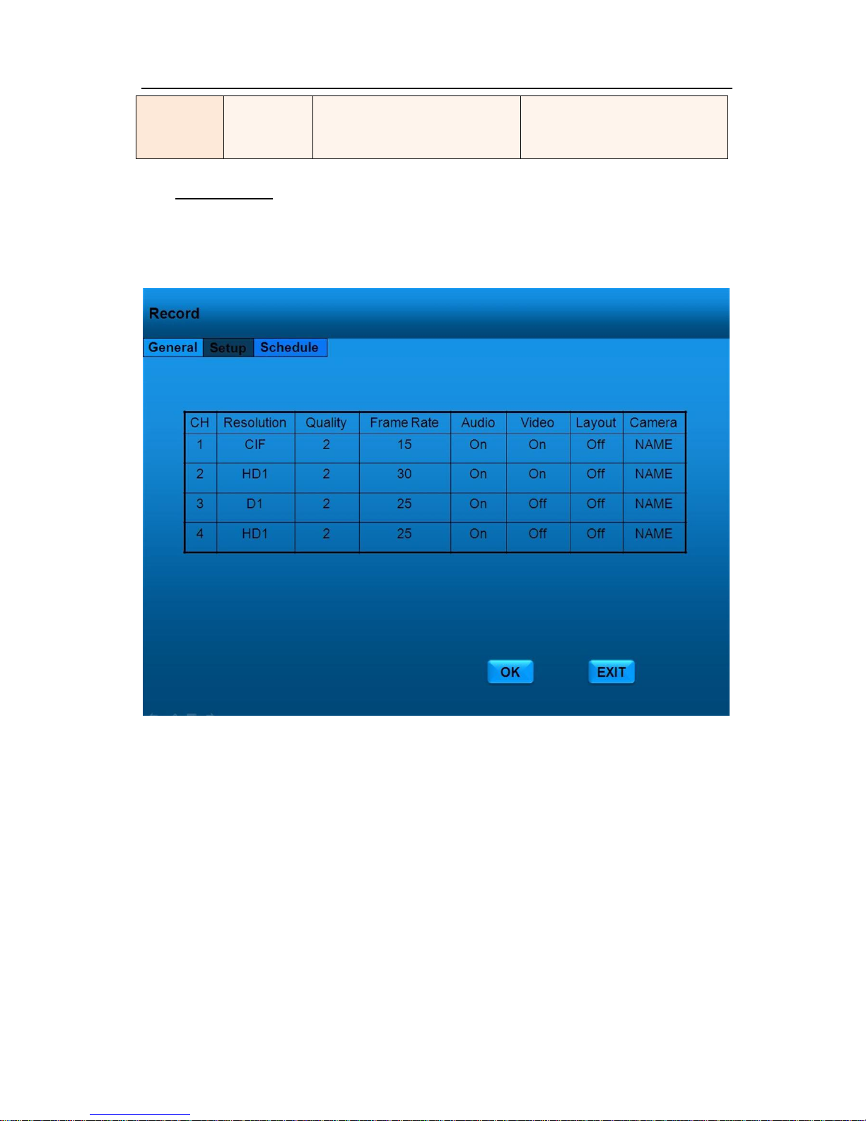
Move the cursor from General to Setup. Here you can set the recording quality, frame rate
and audio record and you can name the cameras.
CH: a check represents that this channel will be recorded*
Resolution: Select among CIF, HD1 and D1:
CIF: Resolution at 360x240 (NTSC), 352x288 (PAL)
HD1: Resolution at 720x240 (NTSC), 704x288 (PAL)
D1: Resolution at 720x480 (NTSC), 704x576 (PAL)
Quality: 1-5, with 1 being the highest video quality and 5 being the lowest
Frame Rate: 1, 2, 4, 8, 15, or 30 frames per second
Audio: ON or OFF for audio recording for each channel***
Layout: a check indicates that this channel will be previewed on the video monitor output
feeds through the front and back video ports of the DVR.
Camera: Input the name you want to display in videos & monitor
Page 39
- 38 -
Select 【OK】on the GUI and press 【ENTER】on remote controller to save alarm information. Press
【EXIT】on the GUI or remote controller to return Main Menu without any change.
Record Schedule
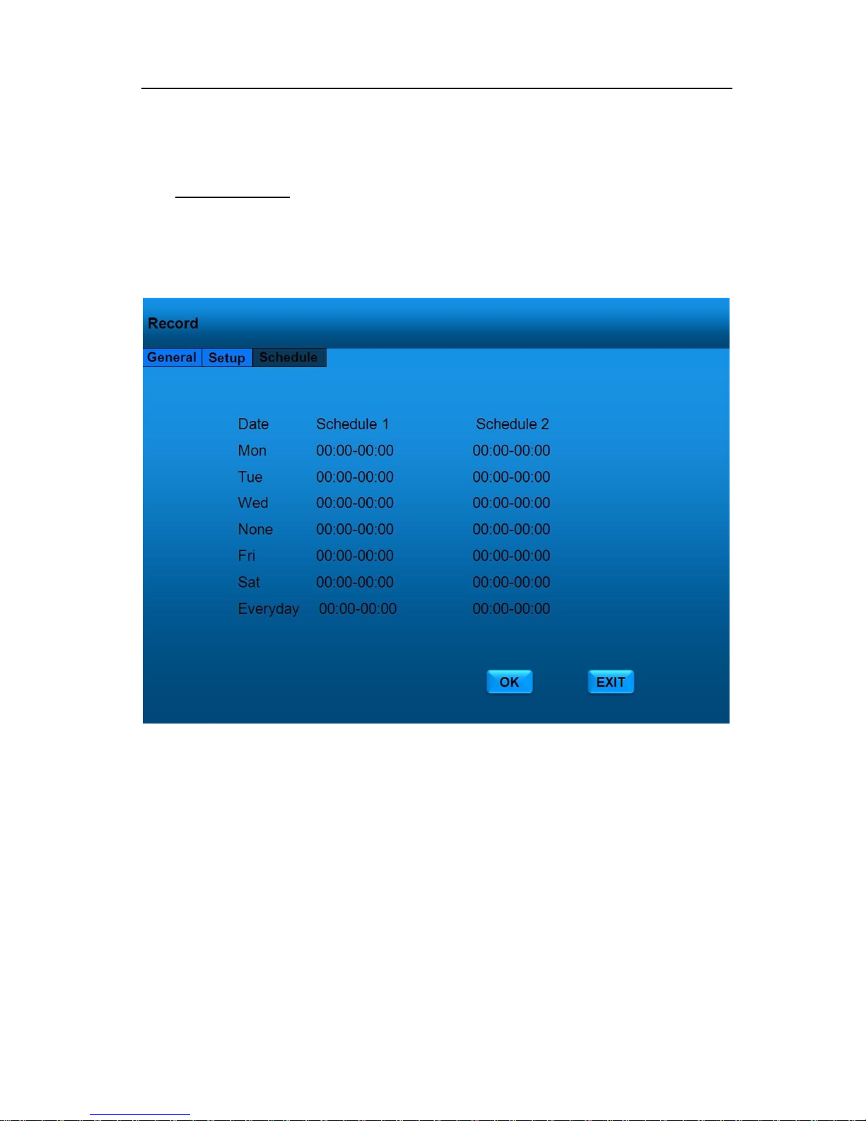
Move the cursor to Schedule. Here you can setup the recording time segment. Please confirm
the System Wiring – Power mode as shown in P.18.
The Schedule section of the menu is where the user can set the times that the DVR will
automatically turn on and shut off. There are 3 subsections of this section: DATE, SCHEDULE 1,
and SCHEDULE 2. The DVR start up mode is configured Timer Mode.(in the Record >>General in
P.18 section)
Date: Mon, Tue, Wed, Thurs, Fri, Sat, Sun, Everyday..
Schedule1: Start Time – Stop Time (00:00-24:00)
Schedule 2: Start Time – Stop Time (00:00-24:00)
Select 【OK】on the GUI and press 【ENTER】on remote controller to save alarm information. Press
Page 40
- 39 -
【EXIT】on the GUI or remote controller to return Main Menu without any change.
any change.
USERS
Your MDVR has multiple layers of security to protect against intrusion. Users have limited access
to setup features while the Administrator has full access to all configuration options. CAUTION: DO
NOT LOSE THE ADMINISTRATOR PASSWORD.
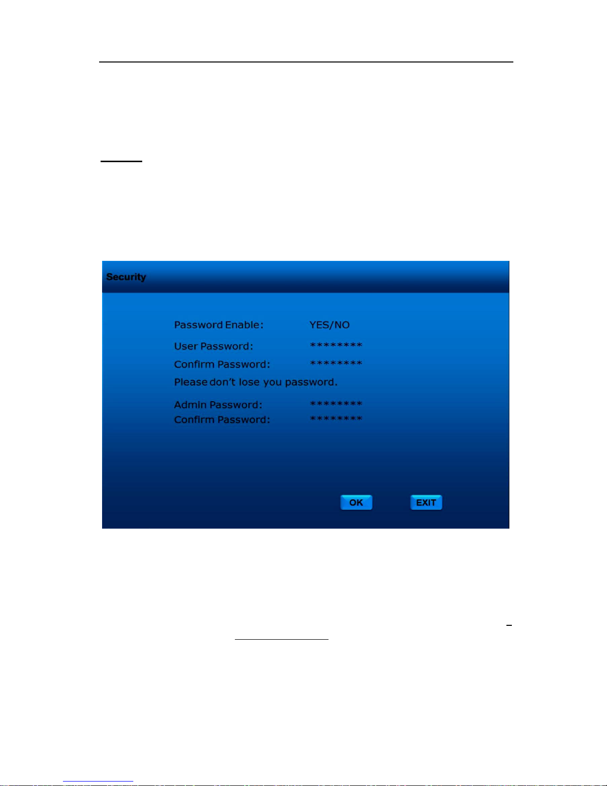
Select SECURITY. Press【ENTER】key to setup USER password.
PASSWORD ENABLE: Selecting “ENABLE” will require a password in order to access the
setup menu. Selecting “DISABLE” will not require a password. Administrator has full rights and a
User has limited rights to view.
Password Enable: Press 【ENTER】 to switch between "YES” and “NO” .
User Password: Enter the desired password and confirm. The password must be 6
numerical characters in length. Use the NUMERIC keypad on the
handheld to input the values.
Confirm Password: Re-enter: must be same input as User password, otherwise the
system would not accept the password setting when password
does not match between first lines and re-entered line.
Page 41
- 40 -
Press the down CURSOR to highlight the administrator password entry line.
Admin Password: Enter the desired password and confirm. The password must be 6
numerical characters in length. Use the NUMERIC keypad on the
handheld to input the values.
Confirm Password: must be same input as Admin password, otherwise the system
would not accept the password setting when password does not
match between first lines and re-entered line..
Select 【OK】on the GUI and press 【ENTER】on remote controller to save alarm information. Press
【EXIT】on the GUI or remote controller to return Main Menu without any change.
SYSTEM
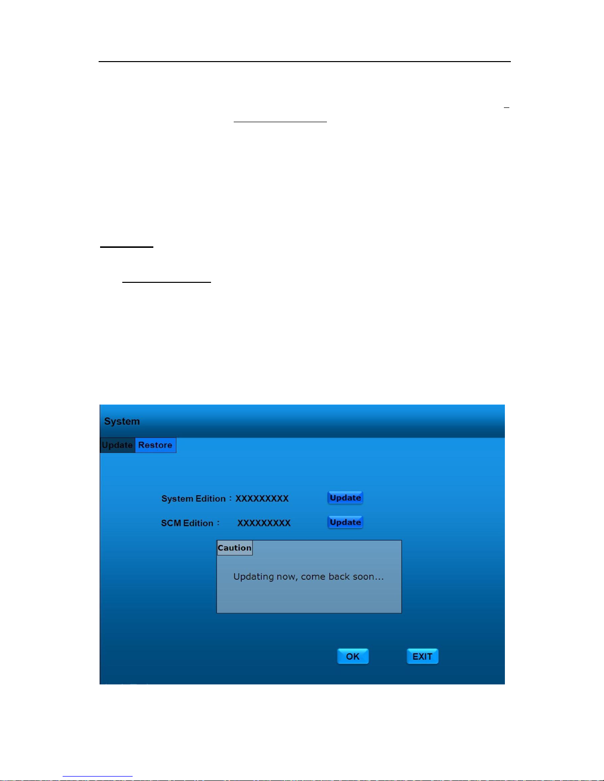
Firmware Upgrate
When improvements, bug fixes or new feature become available for your MDVR the firmware
(DVR operating system) can be easily upgraded in the field. There are several ways this can be
done: through the front panel USB connection, or through the removable hard drive module.
We will provide the firmware upgrade. Correspondingly, the CMS server software components
will upgrade automatically when connected to the Internet.
Page 42
- 41 -
Due to improvements in technology and the availability of new features, our MDVRs comes with
the ability to have the firmware (DVR operating system) be easily upgraded in the field. There are
several ways this can be done: through the front panel USB connection, or through the removable
hard drive module.
We will timely upgrade the firmware once we find the software defect or important bugs. The
CMS will upgrade automatically when connect with Internet.
Select 【OK】on the GUI and press 【ENTER】on remote controller to save alarm information. Press
【EXIT】on the GUI or remote controller to return Main Menu without any change.
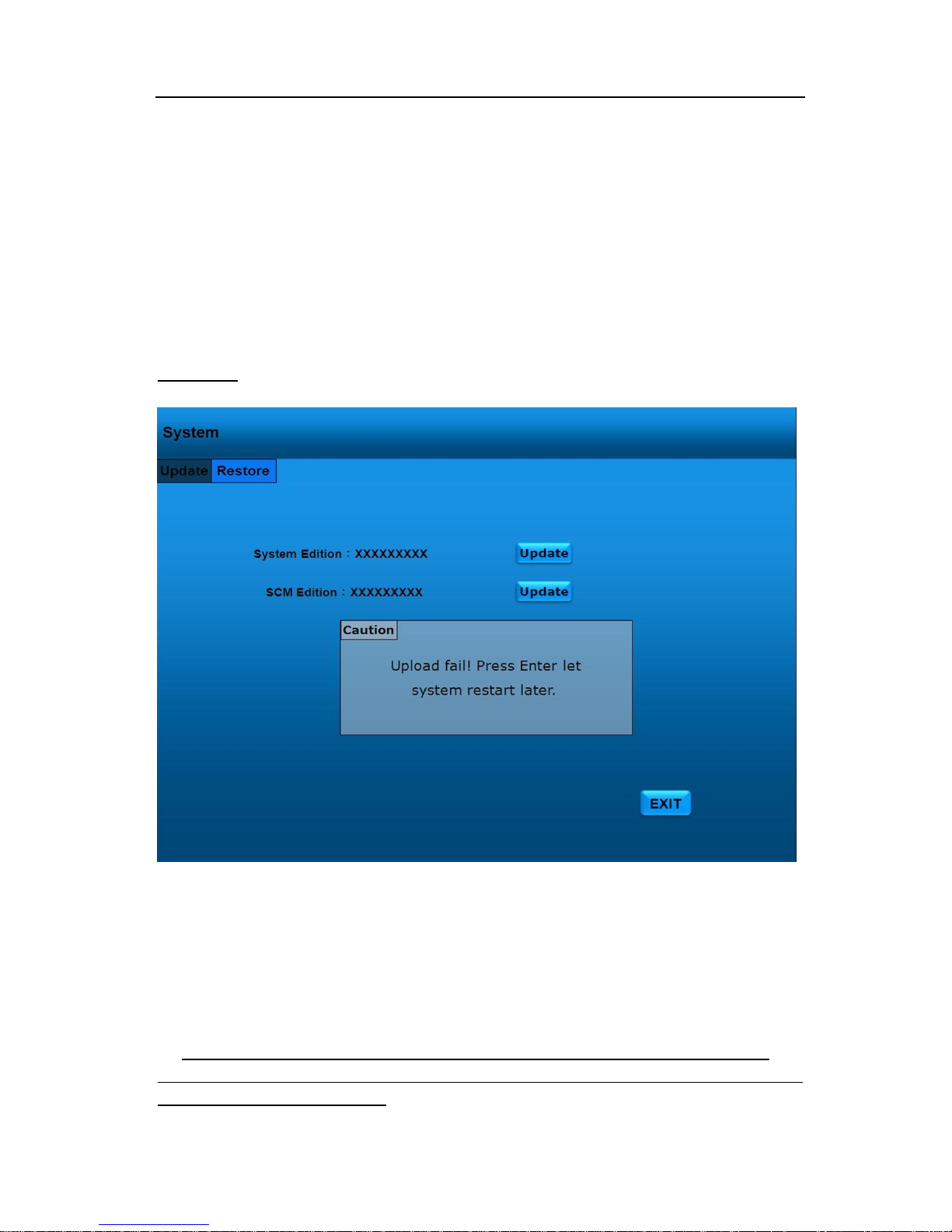
Update Fail
To upgrade the firmware on the DVR, you must put the upgrade file in the ads directory on the
hard drive. The DVR will recognize this file and automatically perform the upgrade. Once the DVR
has finished upgrading itself, a message will appear indicating a successful update has taken place
and a bootstrap algorithm will restart the DVR.
NOTE: Please firmly connect the USB flash memory disk and the hard drive or SD card
containing the latest edition of firmware. Updates are available on our website or you can contact
your local distributor in your area.
Page 43

- 42 -
Press【EXIT】to return Main Menu without any change.
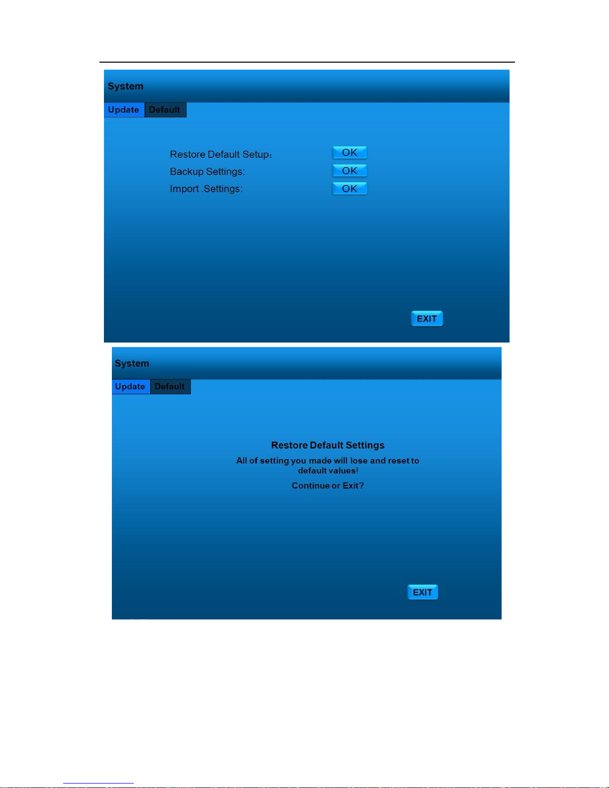
Reset Default
Your MDVR has the option to have all of the configuration settings reset to the factory defaults.
Executing this function is irreversible and once the settings have been changed,
the user must either manually change the settings using the USB flash drive to
upload the new configuration file, placing the configuration file on the hard drive with
Windows Explorer, or using the PC remote management software to change the
configuration.
!! Warning !!: Once the default setup has been loaded, all user settings will be lost.
Page 44
- 43 -
To select 【ENTER】to clear all personal setup and return default setup and 【EXIT】 to discard all
changes and keep the current setup.
Page 45
- 44 -
NETWORK
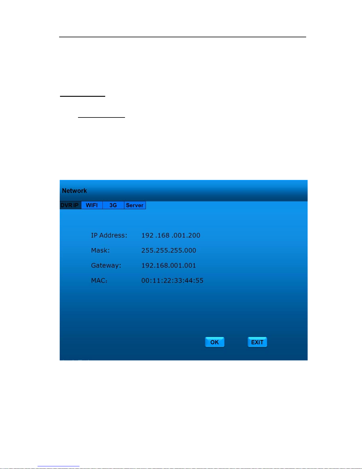
DVR IP Options
You must enter a static IP address to use the Network capabilities. Please consult with local
Internet Service Provider or your Information Technology group for the correct IP address. Use
Number keypad to enter the TCP/IP address information:
Select Network >> DVR IP
“IP Address”: Enter the static IP address
“MARSK”: Enter the subnet mask
“GATEWAY”: Enter the gateway
"MAC" The unique code in each machine. - IT CANNOT BE CHANGED.!!
Page 46
- 45 -
Select 【OK】on the GUI and press 【ENTER】on remote controller to save alarm information. Press
【EXIT】on the GUI or remote controller to return Main Menu without any change.
Wi-Fi Options
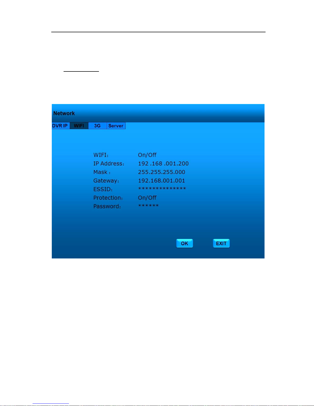
Use CURSOR to select WIFI section. Press 【ENTER】 to access input settings. WIFI module
will offer partially live surveillance if your route has enough WLAN resources.
“WIFI”: Select ―ON‖ if you want to use wireless communication
“IP Address”: Enter the static IP address of the Wi-Fi transceiver
“MARSK”: Enter the subnet mask
“GATEWAY”: Enter the gateway
"ESSID": The Extended Service Set ID ( ESSID) is the identifying name of a
wireless access point. It allows one wireless network (access point)
to be clearly distinguishable from another.
“Protection”: When ―ON‖, a password to authenticate will be required
“Password”: Enter your password
Page 47
- 46 -
Select 【OK】on the GUI and press 【ENTER】on remote controller to save alarm information. Press
【EXIT】on the GUI or remote controller to return Main Menu without any change.
3G Options
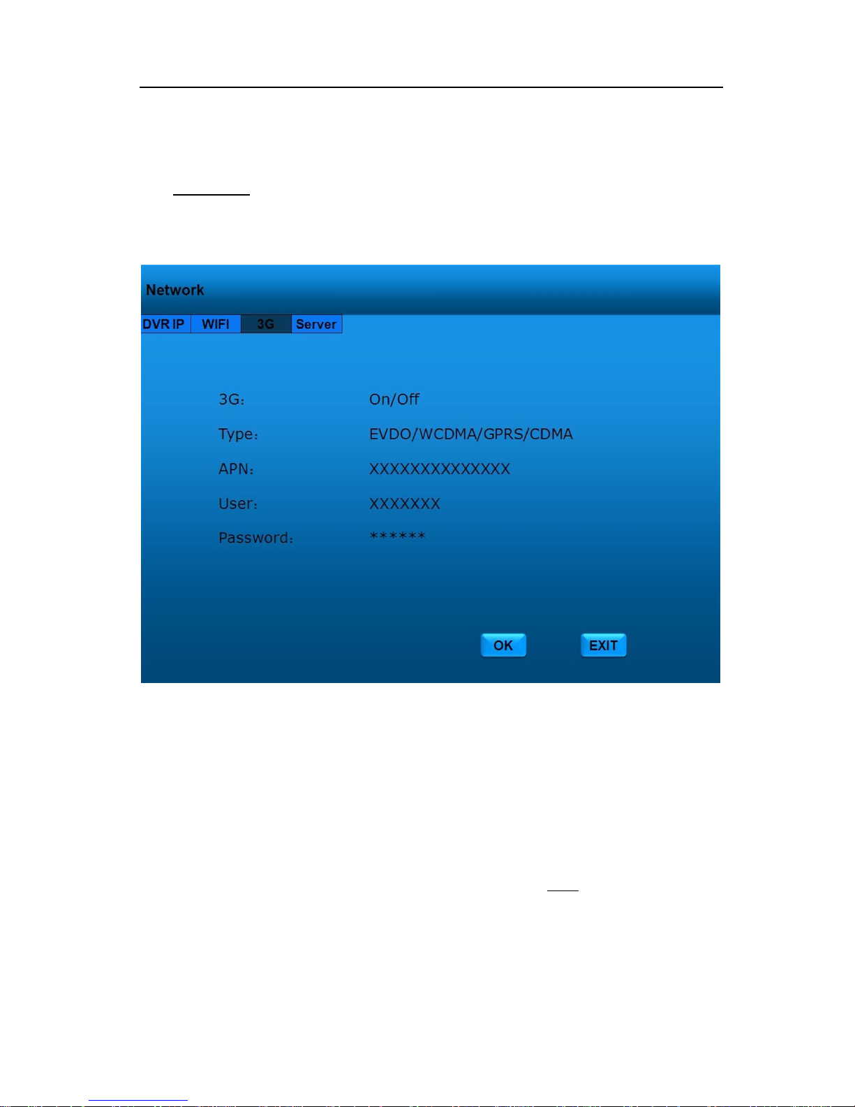
Use CURSOR keys to select 3G menu. Press 【ENTER】 to access input settings.
.
“3G”: Select ―ON‖ if you want to use cellular wireless communication (the
MDVR must have this option at time of purchase)
“TYPE”: MDVR can recognize the 3G module type
“MARSK”: Enter the subnet mask
“APN" Access Point Name (APN) is a configurable network identifier used by
a mobile device when connecting to a GSM carrier. The carrier will
then examine this identifier to determine what type of network
connection should be created.
“User”: Enter you user name
“Password”: Enter your password
Page 48
- 47 -
Select 【OK】on the GUI and press 【ENTER】on remote controller to save alarm information. Press
【EXIT】on the GUI or remote controller to return Main Menu without any change.
Server Setup
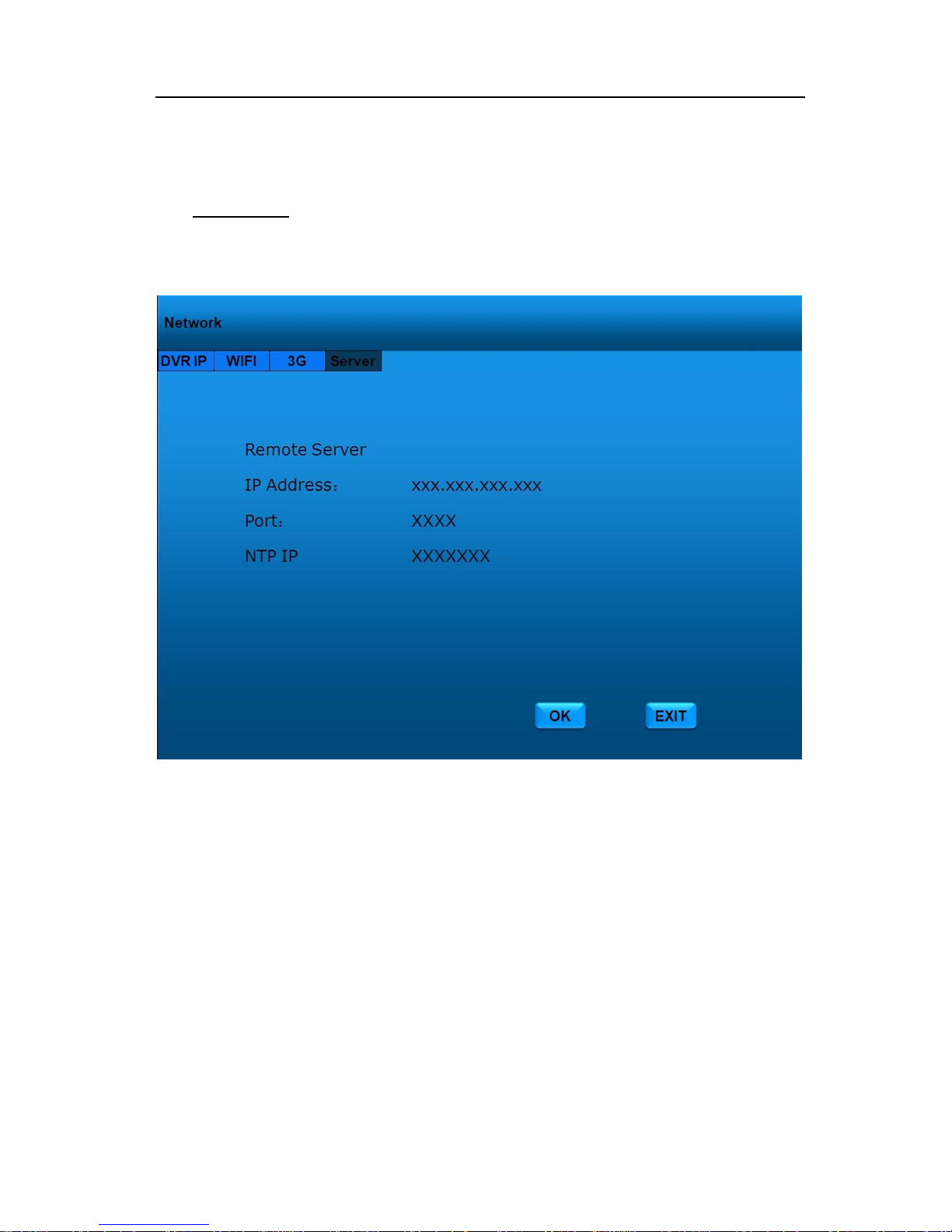
Use CURSOR keys to select Server section. Press 【ENTER】 to access input settings
In the Server section of the Network section, the user can establish the network address
settings for the CMS Network Server. Work with your System Administrator or IT Department for a
suitable network addressing scheme.
IP: the IP address of the Media Server
Port: the control port of the Media Server
NTP IP: the IP address of the Network Time Synchronization Server
Select 【OK】on the GUI and press 【ENTER】on remote controller to save alarm information. Press
【EXIT】on the GUI or remote controller to return Main Menu without any change.
Page 49
- 48 -
Note: See CMS User’s Manual for details and capabilities of the CMS Server and CMS Client.
GPS (Optional)
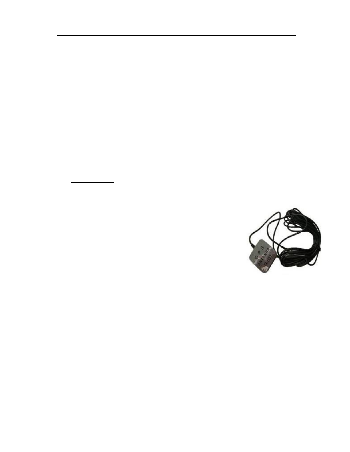
This feature is only available with the system connected with GPS
antenna.
1. To enable the feature make sure to connect the GPS antenna to the GPS
connection port located at the back of docking station.
2. Once connected properly and placed outside the vehicle facing towards
the sky, you will find the GPS icon display on the surveillance screen as
shown:
3. The GPS data will appear on the screen as:
• N/S for longitude
• W/E for latitude
• Vehicle Speed
4. The values of GPS are embedded on the video and could be retrieved by using the video
playback function.
Page 50
- 49 -
3G Online Surveillance System
 Loading...