

Page 1

Dear Customer:
Thank you for purchasing your equipment from Component Playgrounds!!! We are proud of
our commercial grade products made for kids of all ages & sizes, and we are confident that you
will enjoy your equipment for many years.
Because you have purchased a top of the line commercial grade product, you will need to
be aware of some specific shipping requirements that may be different from shipments you
have received in the past through other delivery companies (such as UPS), and you should
follow the guidelines below carefully.
1. In most cases your product will arrive via common carrier truck line directly to your
home with curbside delivery only. This means the driver will facilitate the offloading of the
shipment at the curb, or most reasonable place near the curb and your house. You are then
responsible to have someone physically capable to help unload the product upon delivery
and note the condition of the product as per below instructions.
2. Your product may arrive on a pallet and upon delivery—locate the packing list (usually
attached to the hardware box & orange & black in color) and verify that each piece listed is with
the shipment. *** Please disregard any delivery driver stated “time crunches” or “needs to
leave quickly” and in-speck the product to your satisfaction = this is your product so
make sure it is all there in good condition or noted properly before the driver leaves.***
3. If there are any parts/pieces missing, note this directly on the delivery receipt BEFORE
you sign and receive your copy of the receipt, with wording such as “missing xyz part” etc.
Note: some shipments will have more than one pallet so check both before noting missing.
4. Similar to #3 above, also note the condition of the pieces and if any parts have been
damaged in shipping note this directly on the delivery receipt BEFORE you sign and get your
copy from the driver (in particular inspect slides for damage).
5. If your shipment appears to have damage and /or missing pieces, a freight claim must
be fi led with the freight company w/in two business days. Component Playgrounds will assist
you with this process if it is necessary. Contact the shipping manager toll free @ 877-530-0222
for claims assistance.
6. Ask your driver to sign or initial the freight slip acknowledging any damage or
discrepancies.
7. Get a copy of the signed delivery receipt from your delivery driver BEFORE he leaves.
8. If you are concerned or don’t know what you should do with a certain situation
regarding the shipment, please call the shipping manager toll free @ 877-530-0222 before the
driver leaves.
All shortages and damaged items are the sole responsibility of the carrier. You are
responsible to notify Component Playgrounds of any shortages or damage relating to your
shipment w/in 2 business days of receipt of your equipment. After this time, any claim for
shortage or loss cannot be honored.
Component Playgrounds cannot be responsible for replacement of any parts,
missing or damaged, that have not been properly noted on the delivery receipt.
Component Playgrounds cannot be responsible for damaged or missing pieces due to
the fault of, or loss by the freight company.
Thanks again & remember to tell your friends about your product from Component Playgrounds!
Page 2
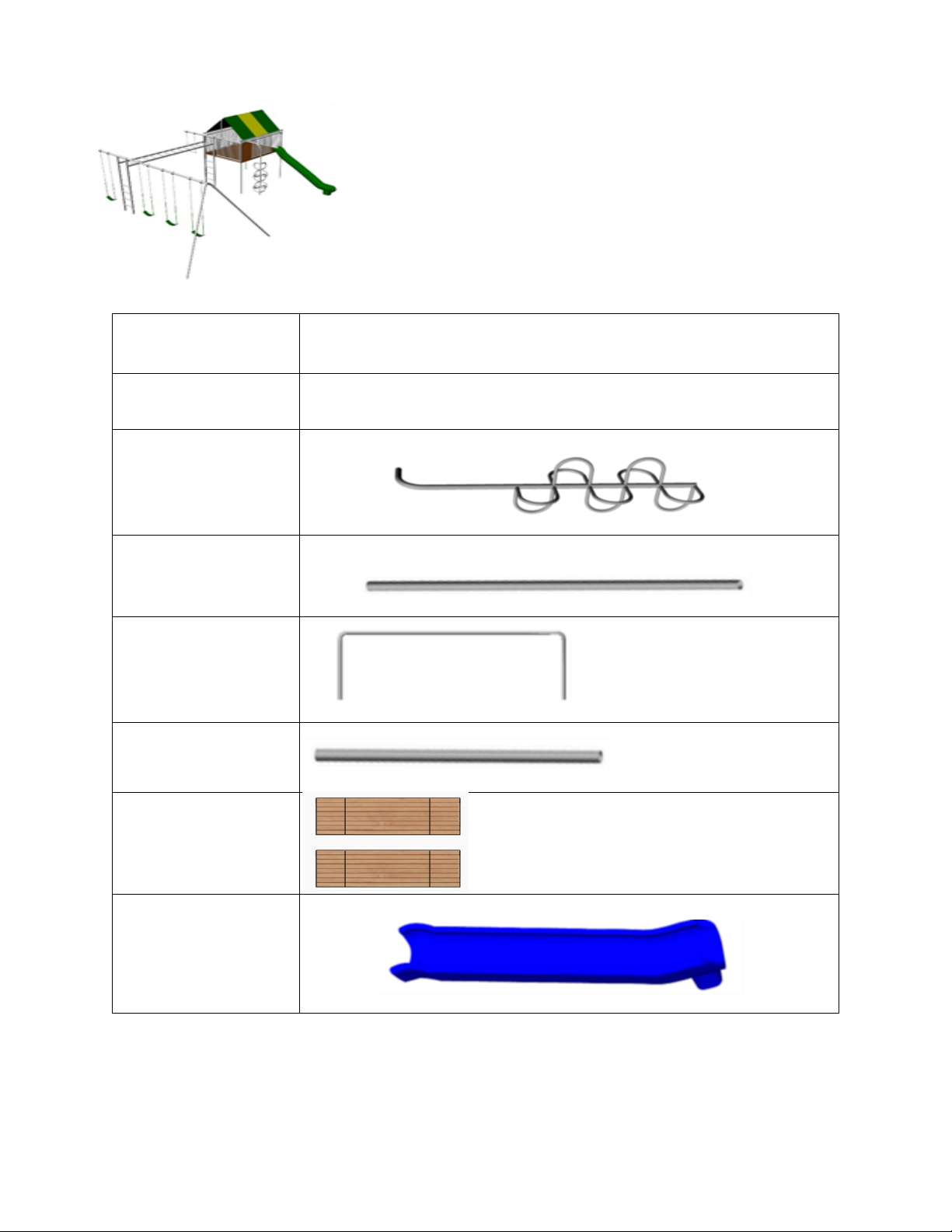
Quantity
Description
2
Box Containing Swing Set Parts
1
Wild Climber
2
Side Canopy Support
1
Center Canopy Support
4
2 3/8” x 6’
Clubhouse Legs
2
CH Plastic Deck Package (3
Bundles Total of 16 Boards)
1
Slide
Parts Identification
CH45 Swing Set
(Page 1 of 3)
Page 3

Parts Identification
Quantity
Description
1
6’ CH Center Opening Barrier
1
6’ CH One Opening Barrier
1
8’ CH Full Barrier
1
8’ CH Two Opening Barrier
1
12’6” Horizontal Ladder
2
8’ Upright Ladder with Sleeves (Actual length 10’)
CH45 Swing Set
(Page 2 of 3)
Page 4
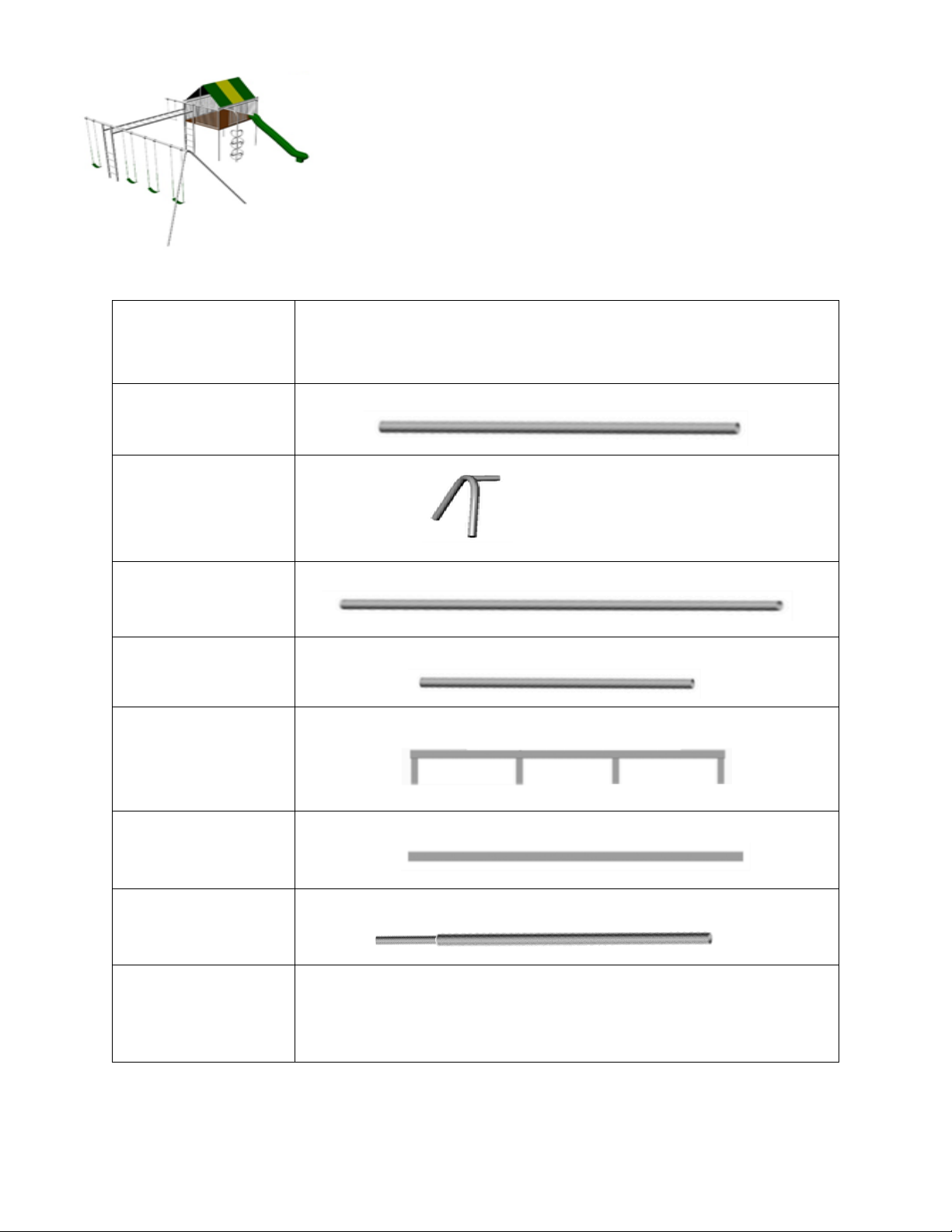
Parts Identification
Quantity
Description
2
1 7/8” x 9’ Leg
1
Triple End
1
2 3/8” X 11’7” Top rail
1
2 3/8” X 5’6” Top rail
2
6’ Long square tubing floor joists with stubs
4
7’8” Square Tubing Floor Joists
1
2 3/8” X 5’6” Top rail with insert
32
Total Pieces
CH45 Swing Set
(Page 3 of 3)
Page 5
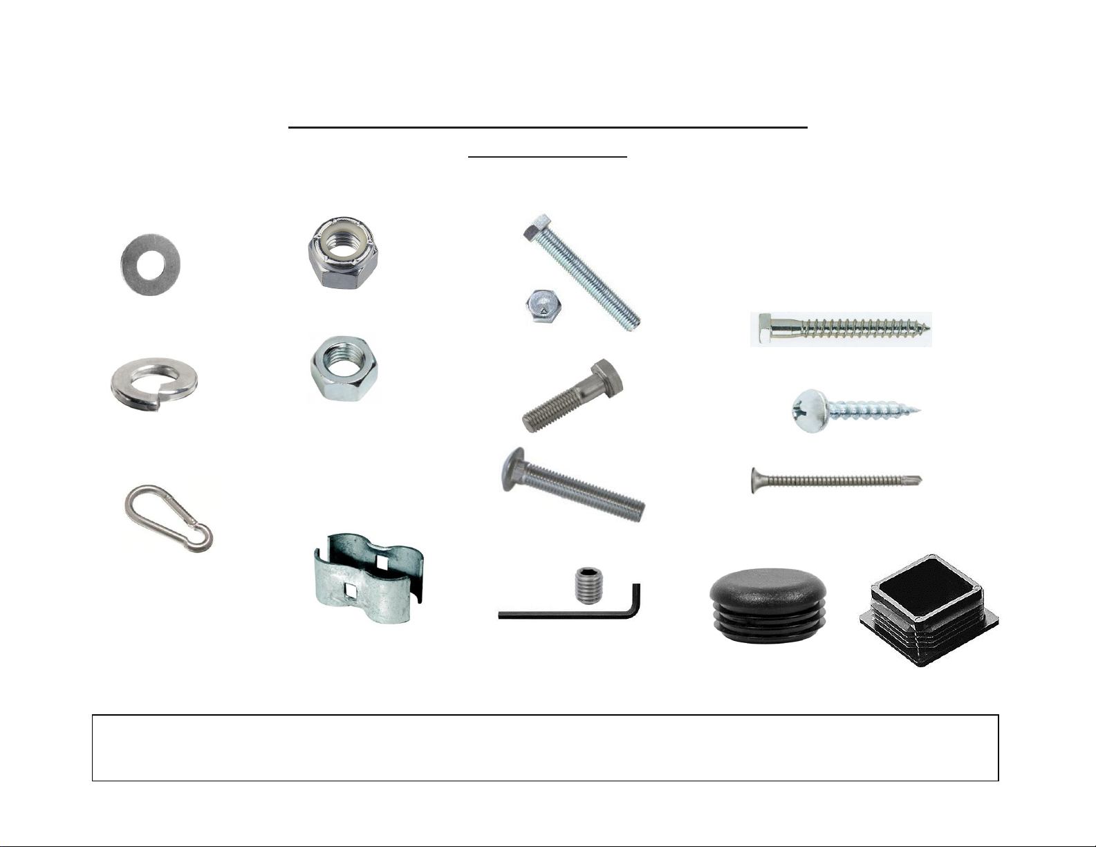
CH45 Swing Set Parts Identification Page
Flat Washer
Loc Washer
Nyloc Nut
Hex Nut
Tap Bolt
Carriage Bolt
Set Screw with Allen Wrench
Lag Screw
#14 Truss Screw
2 ½” Self Tapping Screw
Carabineer/Spring
Clip
Panel Clamp
Plastic Plug
CH Deck Plug
Pictures are not to scale. The purpose of this sheet is to give you a general idea of the shape and names of the
parts of your swing set.
The Small Parts
Page 6

Installation Instructions
CH45
Required Crew: 2-4
Required Concrete: 20-25, 80 lb bags
Required Tools:
Wheelbarrow Shovel
Level Open end or Box Wrench’s: 5/8”, 9/16”, ¾”
Digging Bar or Pick Ratchet Handle & Sockets: 5/8”, 9/16”, ¾”,
17mm, 7/16”, 11/16”, ¼” deep socket
Allen Wrench (provided) Drill: Cordless or electric, or impact driver
Hammer or Mallet 13/64” and ¼” drill bit, Philips driver bit
Marker Pen Step Ladder (6’or taller)
Tape Measure Small Philips screw driver
Component Playgrounds is concerned about the safety of your vision. It is important that you
choose to protect your vision by wearing proper safety glasses during each and every phase of
this construction process.
PLEASE READ AND UNDERSTAND ALL INSTRUCTIONS BEFORE BEGINNING
The CH45 can be installed as a one day project. The normal time required to install the CH45 is
about 6 – 7 hours for a two to four man crew. This time requirement will vary dependent upon the
composition of the soil and the speed of the installers.
As we have talked to past customers who have installed this product, we have found that most people
prefer to break up the installation project into a two or three day process. As a result of these
conversations, these instructions have been rewritten into a format that we hope will be more helpful
to the casual installer. If you plan to install this playground in one day, disregard the phases and
completely assemble the CH45. Mix and pour the concrete as the last step.
The benefit to installing and setting this product in phases is: The first phase will provide rigid
support for attaching the Platform, Climbers, and Slides of this Playground Structure. Having the
floor joists and ladder pre-set will stabilize the system and make it easier to be working up on the
joists to attach the lumber, barriers etc. without risk of knocking the platform out of level or sinking
the Clubhouse Legs into soft soil as a result of body weight and movement.
*Before digging, please obey local laws by notifying your local underground utilities marking
organization*
Page 7
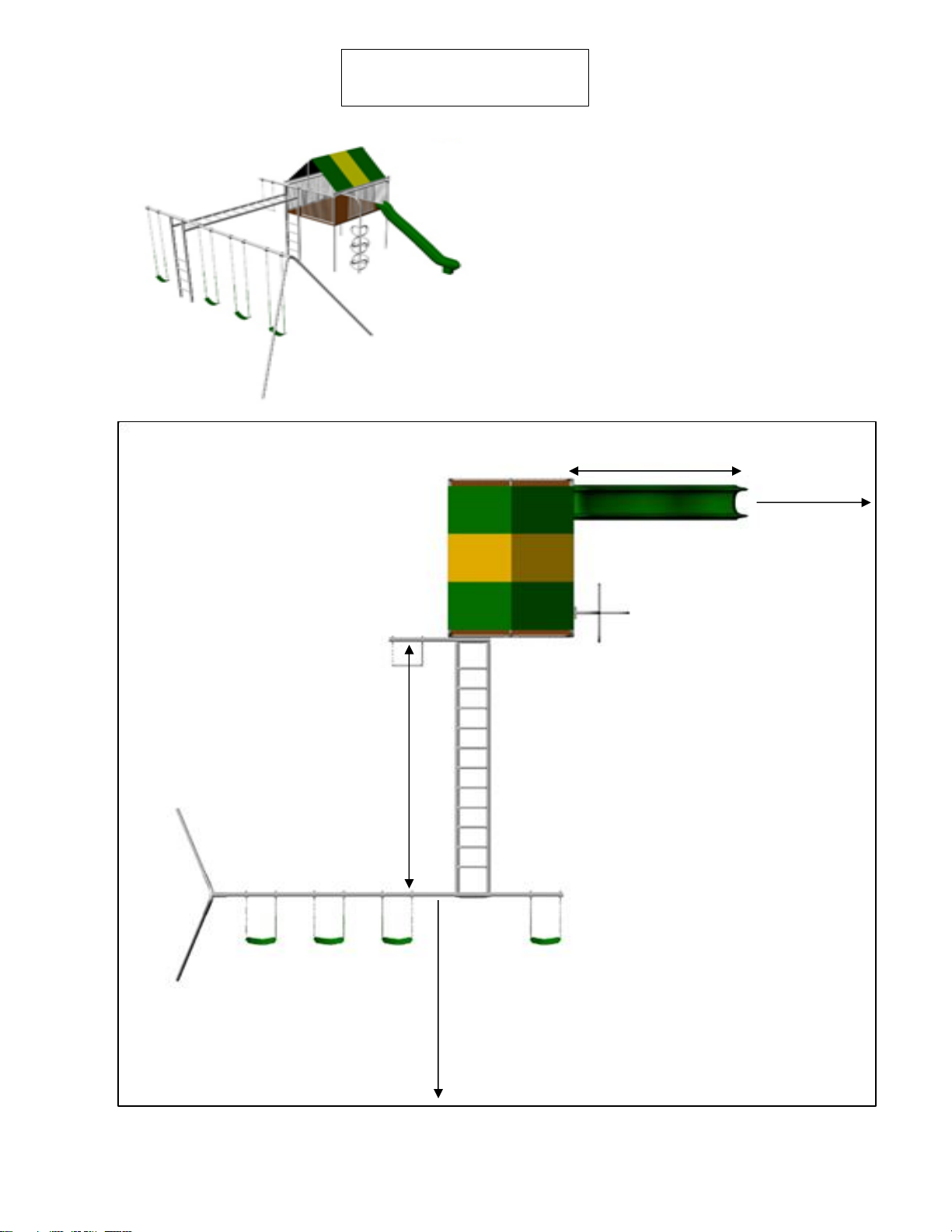
Model CH45
GROUND SPACE 27’ X 27’
MINIMUM RESIDENTIAL PLAY
SPACE 25’ x33’
10’ Swinging Clearance
25’
33’
5’
9’
12’9”
Page 8
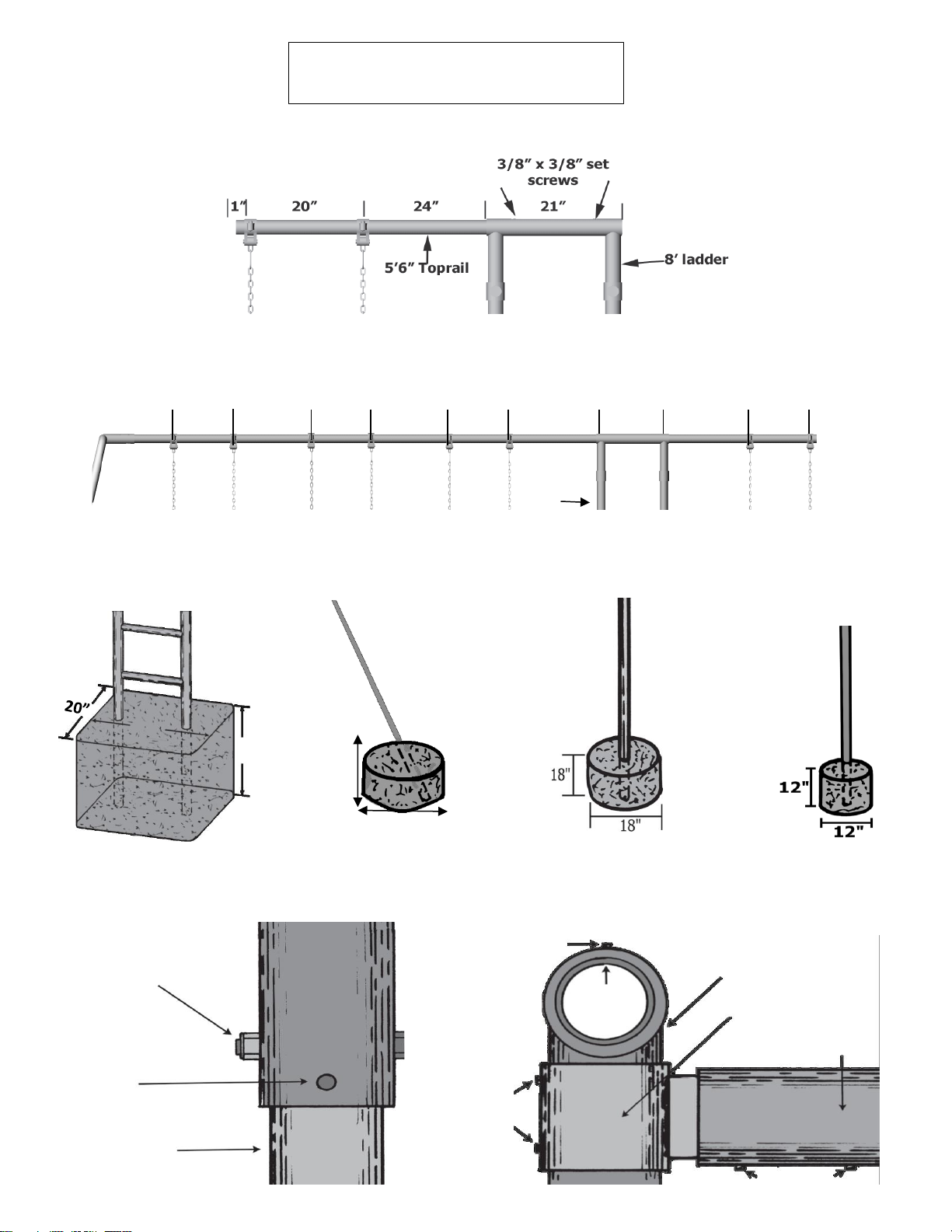
Model CH45 Continued
#1 Top rail Assembly (Clubhouse End)
#2 Top rail Assembly (Swing End)
15”
20”
20”
20”
20”
20”
24”
21”
24”
20”
Ladder
Hole 28”x20”x24” (approx.
6-7 80 lb. bags of concrete
mix per hole.)
Holes 18” x 12” (approx.
1 ½ 80 lb. bags of
concrete mix per hole.)
Holes 18” x 18” (approx.
2 80 lb. bags of concrete
mix per hole.)
Hole 12” x 12” (approx.
1 80 lb. bag of concrete
mix per hole.)
#3 Hole Sizes for cementing in the Set
(a) Upright
Ladder
(b) A-Frame
Legs
(c) Clubhouse
Leg
(d) Wild
Climber
24”
28”
18”
12”
#4 A-Frame Assembly
#5 Horizontal Ladder to Upright Ladder Assembly
3/8” x 2 ¾” Hex Bolt
with 3/8” Nyloc Nut (1
each per leg)
3/8” x 3/8”
Set Screw
(1 each per leg)
Slide in Leg, bolt in
place and secure with
set screw
Triple
End
A-Frame
Leg
Top Rail
Set Screw
Upright Ladder
Adjustable Sleeve
Horizontal Ladder
Set Screws
Set Screws
Page 9
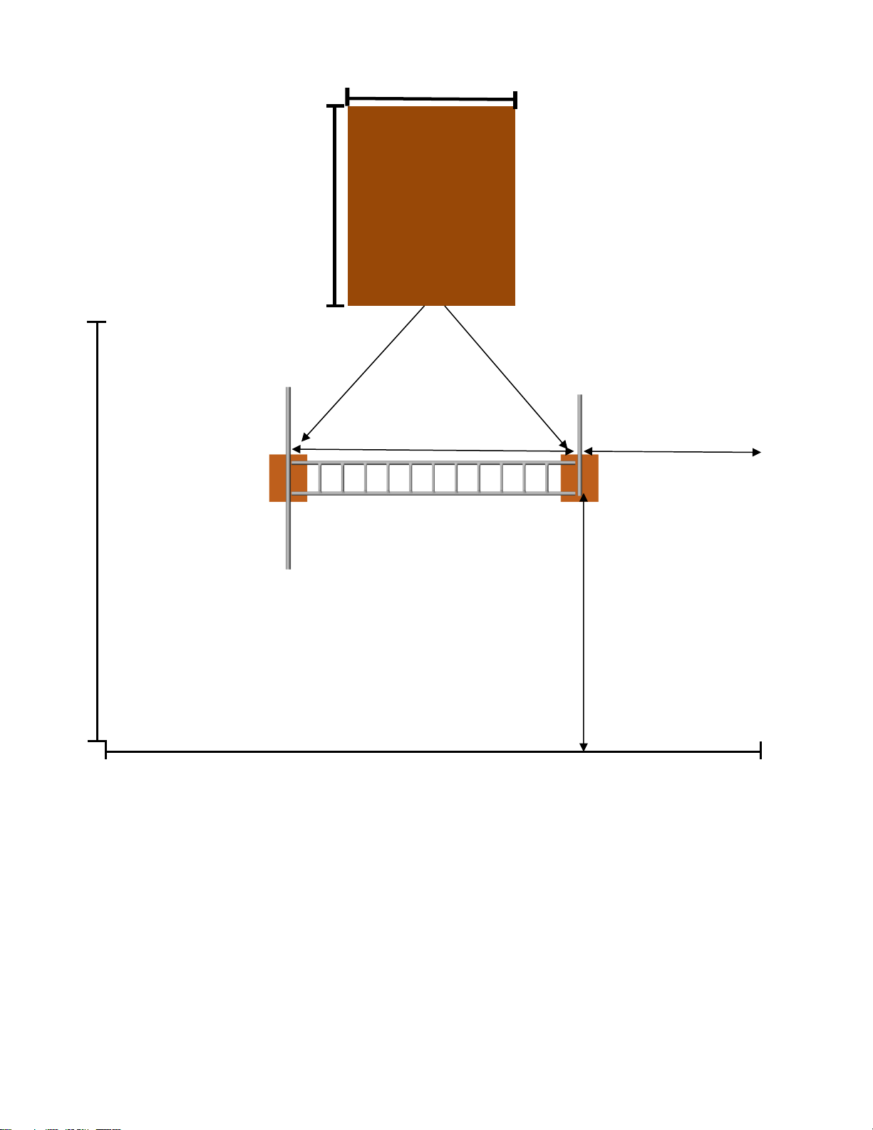
Hole size is 28” wide
by 20” long by 24”
deep.
26’
33’
1.c. Place the 5’ 6” top rail, 12’ 6” horizontal ladder, and 9’ top rail in the play space as shown below. Mark
where the ladder holes will need to be dug. Remove the top rails and horizontal ladder and dig the ladder hole
to the measurements specified below.
17’1” Top
Rail
5’6” Top
Rail
12’6”
10’
18’
To the end
of the top
rail
20”
Page 10
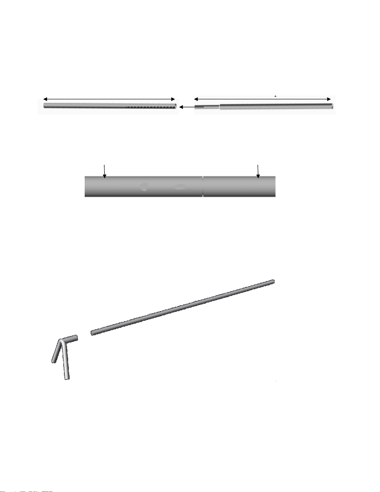
2.a. To assemble 17’1” top rail take the 11’7” top rail and the 5’6” top rail with welded 1 7/8” pipe. Sleeve
the 24” of 1 7/8” into the 11’7” top rail. Now that you have it sleeved all the way in, secure it by using 23/8” set screws and securing them tight (with allen wrench provided) in the 2 holes drilled and tapped at
the top of the 11’7” top rail.
11’7” Top rail
5’6” Top rail
Sleeve 18” x 1 7/8” pipe into 11’7” Top rail.
Holes for set screws
drilled and tapped
11’7” Top rail
Insert 3/8” set screws
and secure them tight.
5’6” Top rail
Assembling and standing the Swing Structure
3.a. Assemble the triple end to the top rail as shown below.
1. Slide the end of the top rail into the triple end.
2. Insert and tighten set screws into triple end socket with allen
wrench provided.
Page 11
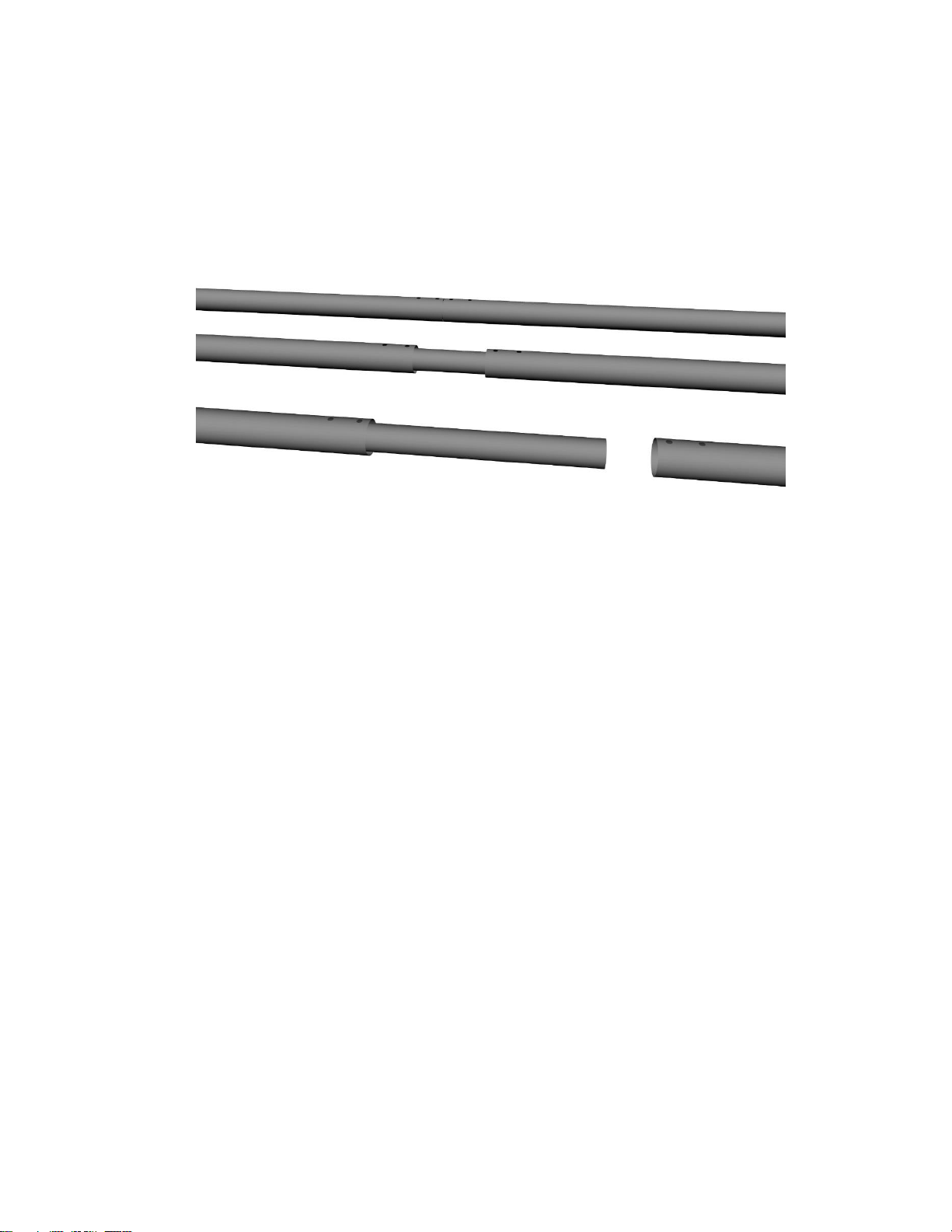
Two piece Top Rail
Assembly
*Make sure to line up the set screws so they make a straight line
as show in the graphic above.
Step 1:
Step 2:
Step 3:
Page 12
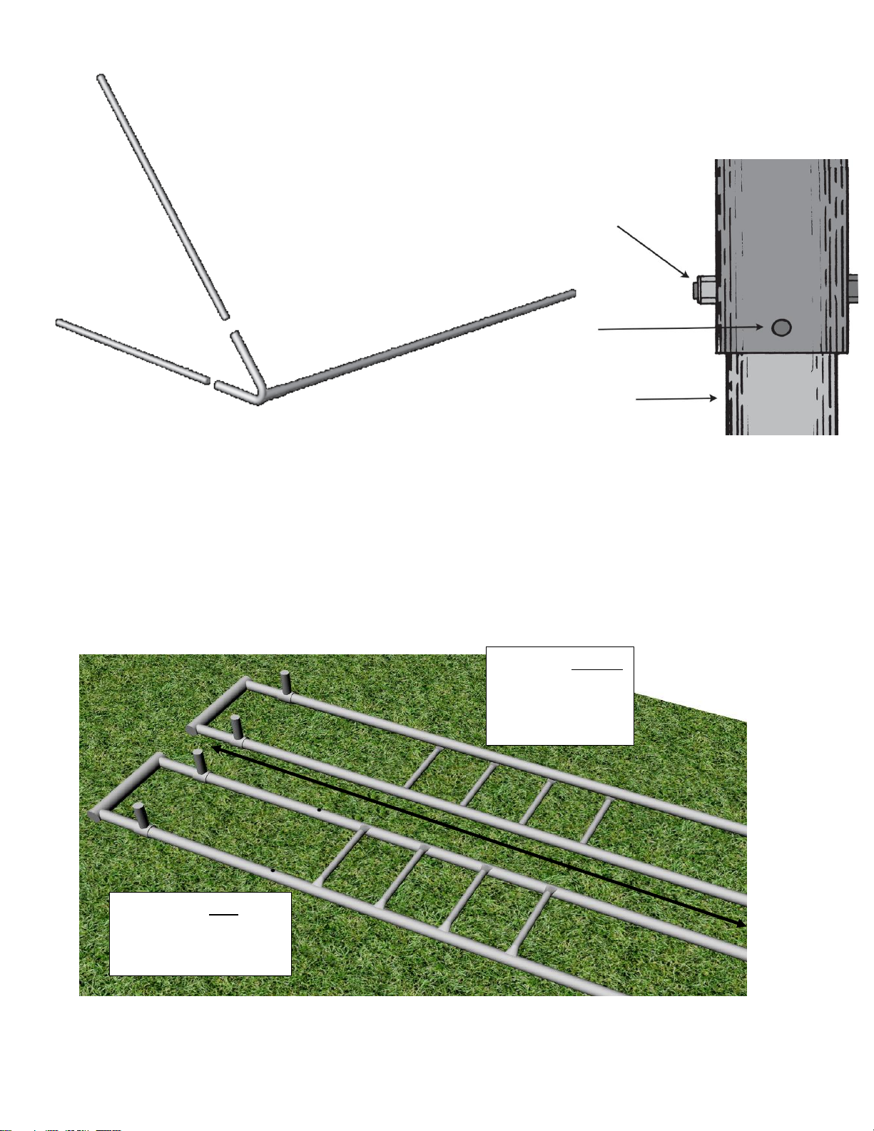
Assembling Ladders and Attaching to deck support structure
4.a. Make a mark 108” up from the bottom of the ladder onto each ladder rail. Move the adjustable sleeves to
these marks and position them to receive the horizontal ladder by turning them to point at a 90 degree angle
(towards what will become the inside of the Horizontal ladder section of the structure.) Secure the set screws.
Notice Direction of the rungs on the ladders:
The Ladder without
the holes drilled
has the rungs
facing down.
The ladder with the
holes drilled has the
rungs facing up.
108”
3.b. Assemble the legs into the triple end and top rail as shown below.
1. Slide the end of the drilled legs into the triple
end.
2. Align the holes in the legs with the holes in the
triple end and join together using 3/8” x 2 ¾”
hex bolts and 3/8” nyloc nuts.
3. Insert and tighten set screws into triple end
with allen wrench provided.
Triple
End
A-Frame
Leg
Page 13
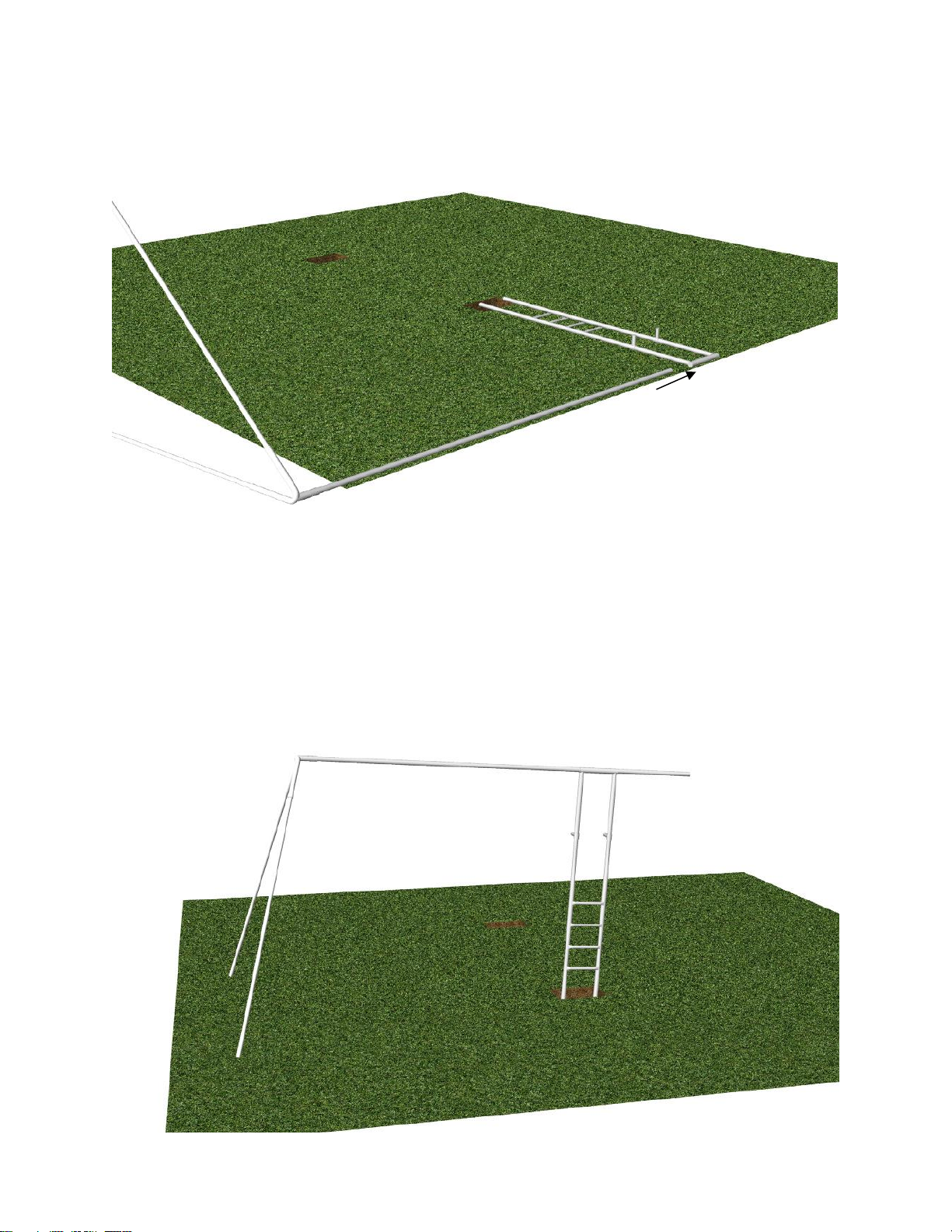
5.a. Position parts as shown below and insert assembly into ladder. Use the mark previously made on the
top rail to show you how far the assembly needs to be inserted. Insert set screws into the ladder top sleeve
and tighten until barely snug. Do not secure them at this point.
Notice Ladder rungs are
facing down.
Slide through top sleeve
5.b. Using two strong adults lift the ladder and the A Frame end and allow the ladder to fall into its hole. You
can allow the structure to stand but it will not be level at this time.
Situate the ladder and “A” frame legs as desired in the space. Be certain that the top rail has not slid away
from its correct position. If it has moved, hold onto the ladder and adjust its position on the top rail by pulling
or pushing as necessary. When you are content with the position of the top rail within the top sleeve, secure
the set screws in the top sleeve.
Page 14
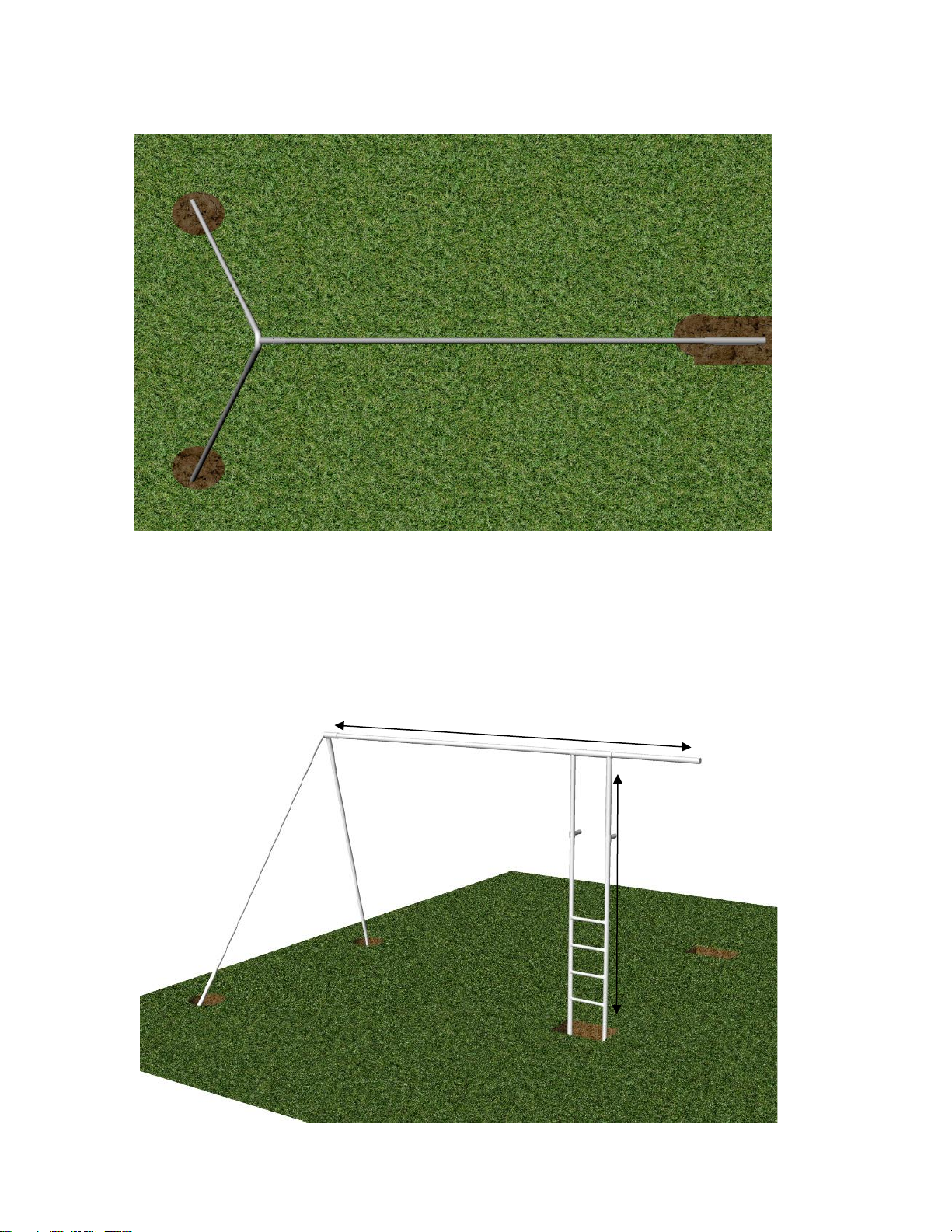
5.c. Make a mark in the soil for the A-Frame leg holes. Move the legs out of the way and dig the holes.
“A” Frame leg
holes are to be
dug at 18” in
diameter by
12” deep.
**Notice
Most of the A-Frame leg hole needs to be dug
towards the inside of the A-Frame leg.
LEVEL
LEVEL
Level Top rail and
upright ladder.
Page 15
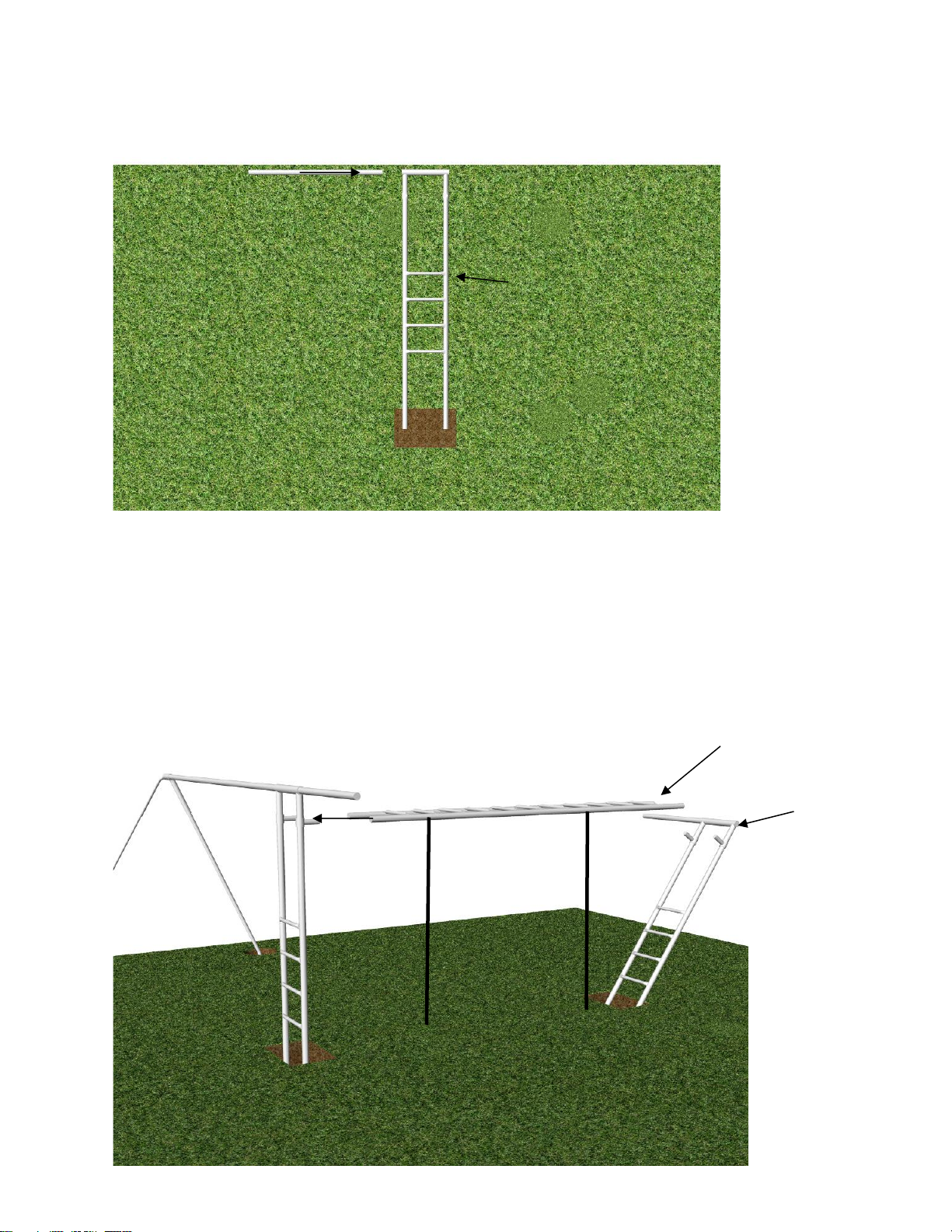
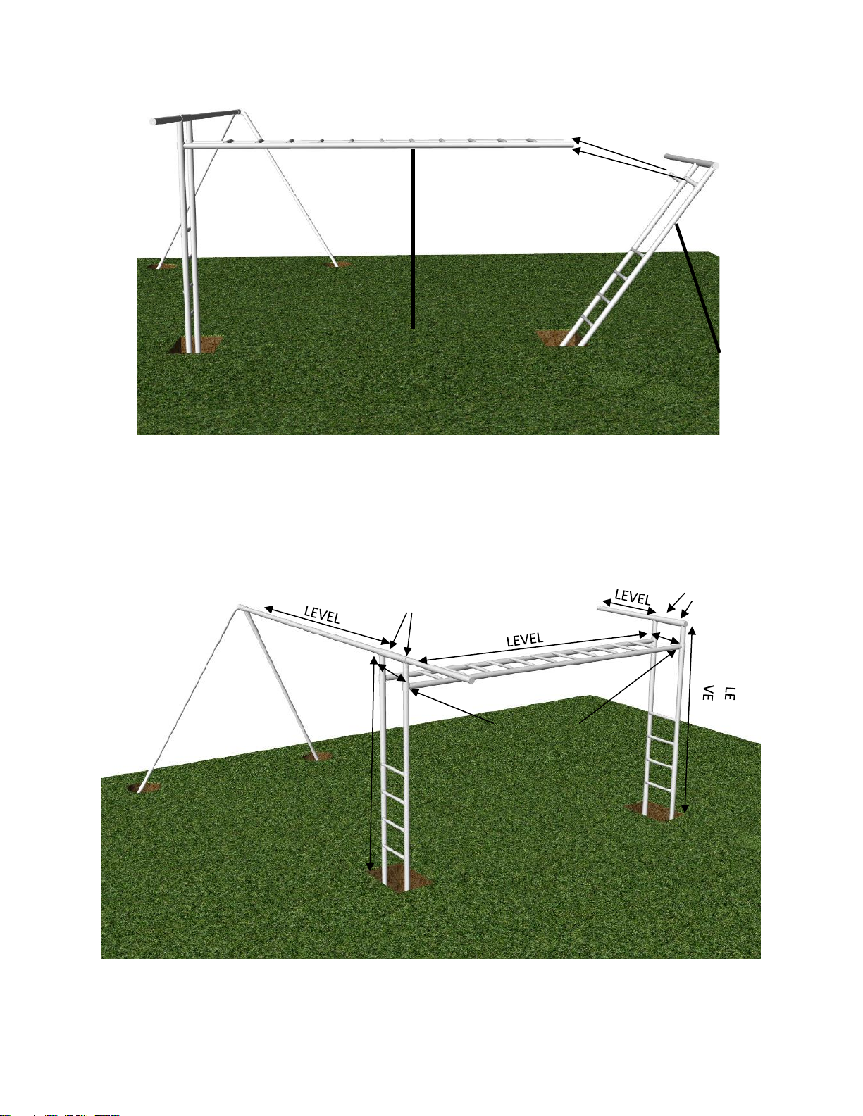
6.a. Set 8’ ladder over the hole, with the rungs facing up. Slide 5’6” top rail into top sleeve. Stand the
ladder in the hole and let it lean back. While you attach the horizontal ladder to the other side.
Slide 5’6” top rail through top sleeve on 8’ ladder
Notice the rungs
are facing up
6.b Before starting this step be sure that the adjustable sleeves are in the correct position. Take the
horizontal ladder and sleeve it onto the adjustable sleeves of the 8’ or 10’ ladder standing. Once
sleeved onto ladder, have person in place #1 take the other ladder that is leaning in the hole and
bring it forward to sleeve it into horizontal ladder. While the person in place #2 stabilizes the
horizontal ladder. Have a hammer handy in case the adjustable sleeves need to be tapped into
Have 2 people stand and support ladder in
places marked below. Sleeve horizontal
ladder onto adjustable sleeves on 10’ ladder.
#1
#2
Notice rungs are
facing up.
8’ Ladder
Page 16
#2
#1
The person in place #1 push the ladder
up and sleeve the adjustable sleeves
into the horizontal ladder.
6.c. Next level out and make any necessary adjustments to level out the play structure. Secure all set screws
(on top of upright ladders, & bottom of the horizontal ladder.
LE
L
Secure set
screws
Secure Set
Screws
Secure Set
Screws
VE
Page 17
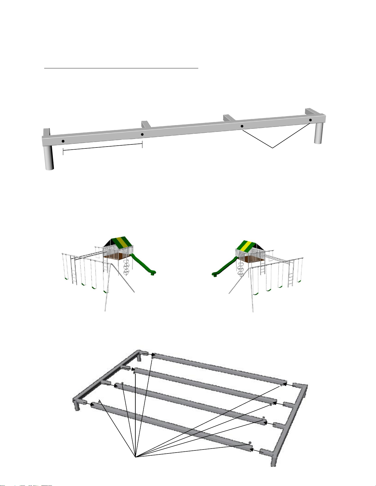
**Important Notice! Please read and understand prior to proceeding**
After configuring your swing
set, plug unused holes with
½” plugs provided.
18”
OR
Assemble and fasten with set screws
facing the inside as shown.
Pre-Assembly: Assembling the Club House Floor Joists
2.a. Locate the Floor Joist End with the four holes in it as shown below and determine which holes
you will be using for your particular swing set configuration. This is the end that will bolt to the
vertical ladder.
Determine which holes you will be using by identifying the configuration below that most closely
resembles the configuration you wish to achieve.
2.b. Assemble the Deck Floor Joist structure as shown below using (8) set screws. Make sure that
the set screw holes are facing inward as shown.
Page 18
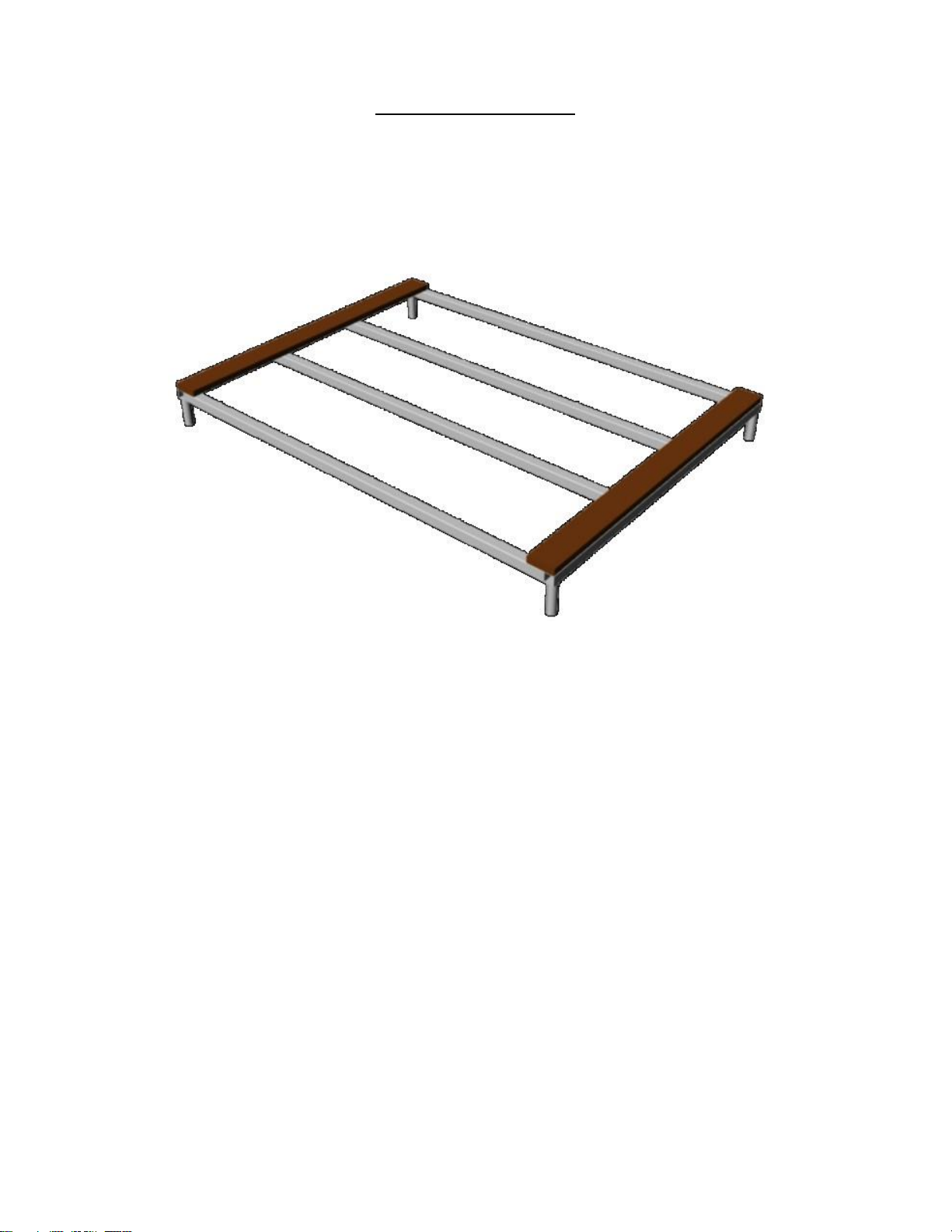
A- Secure the first two boards into place at each end of the platform structure using the 13/64” drill bit to pre
drill the holes through the plastic and into the floor joist. Secure the boards into position using the #14 x 2 ½
pan Phillips SMS. The leading edge of the board should be flush with the edge of the square tubing. Now that
these two boards are secure lay each of the remaining boards up and onto the floor structure and space them
out evenly and to your satisfaction. They will be approximately ½” apart from each other, as shown in the
diagram below.
Installing the plastic Lumber
Tools needed:
Electric drill, 13/64” drill bit, 18 or 20 volt impact driver (preferred tool) or a cordless or electric
drill can be used to drive the screws.
Page 19
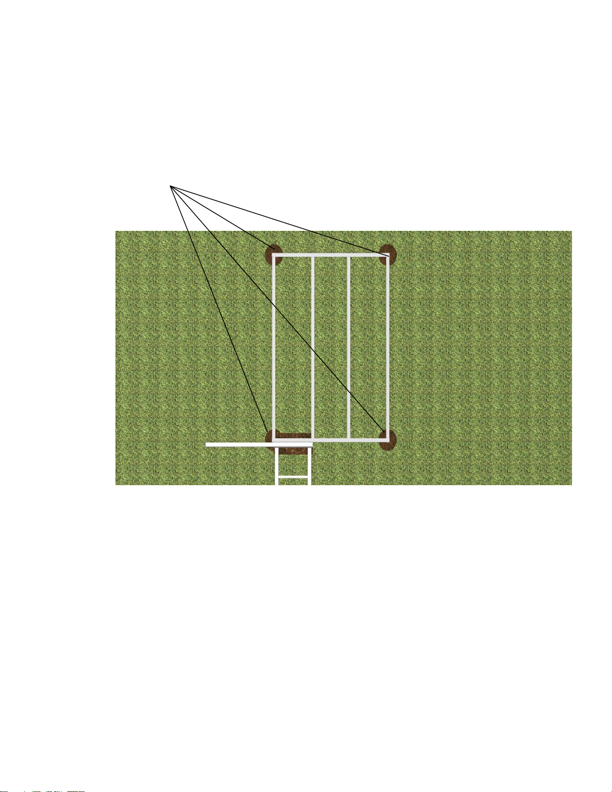
2.c. Position assembled deck frame on the ground as shown below. Mark the holes for the Club
Hole size for Club House Legs is 18”
wide by 16” deep.
House Legs. Dig the holes to the specifications below.
Page 20
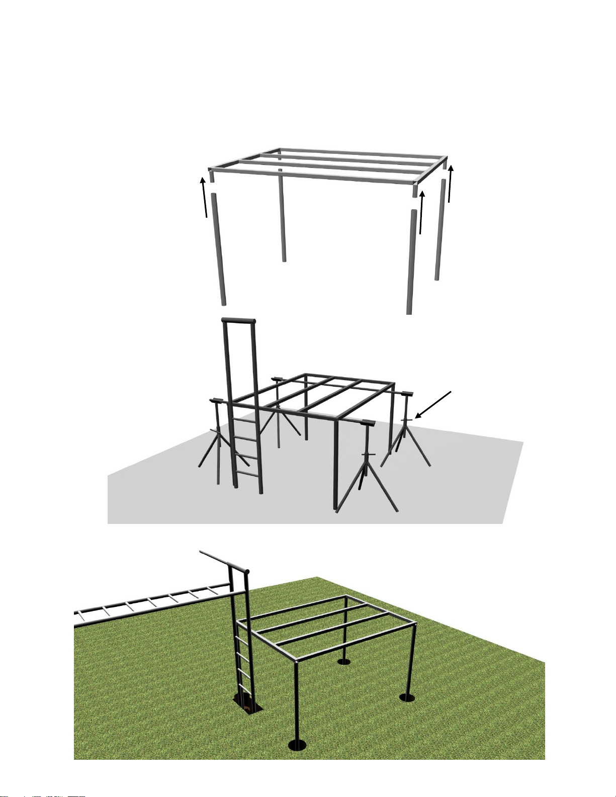
4.b. Having pre-assembled the floor joist system, it is now best to have at least three people to
4.c. Place the assembled structure into the holes previously dug.
Jack stands or
structure to
support platform
assemble the Club House Legs to the floor Joists. Insert all four legs. Then insert and secure one set
screw into each leg to hold them in place. *Note: We suggest you use a structure of some kind to
support the platform as you place the assembled deck structure in the previously dug holes as
shown. (See suggestion below.)
Page 21
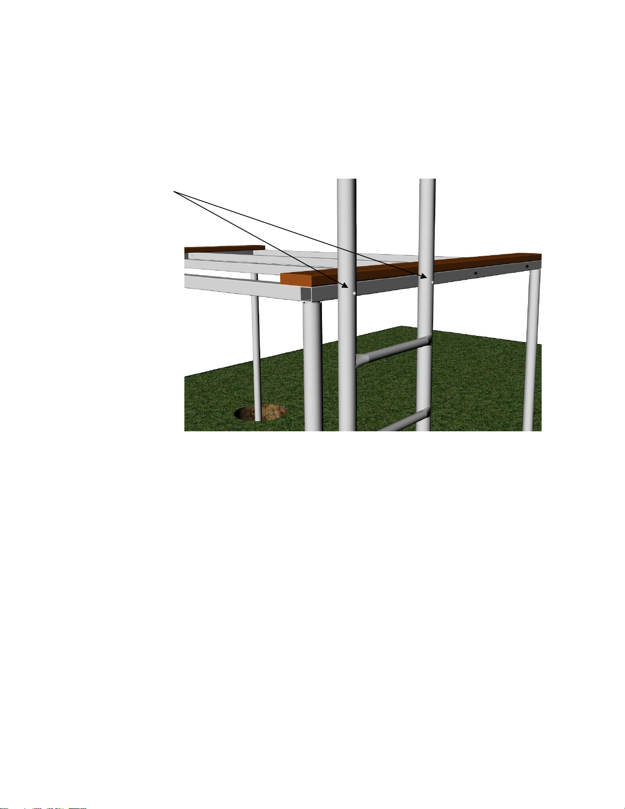
4.d. Attach the Platform Support Structure to the vertical ladder using the 5” carriage bolts
pushed through the ladder and through the support structure as shown, attaching platform to 8’
vertical ladder. You may need to adjust the depth of the individual holes to make the platform
structure and the ladder level up to each other and to make the holes line up.
1. Insert 5” carriage bolts
2. On the back side, place a
3/8” flat washer, followed
by a 3/8” lock washer,
followed by a 3/8” hex nut.
3. Tighten
Page 22
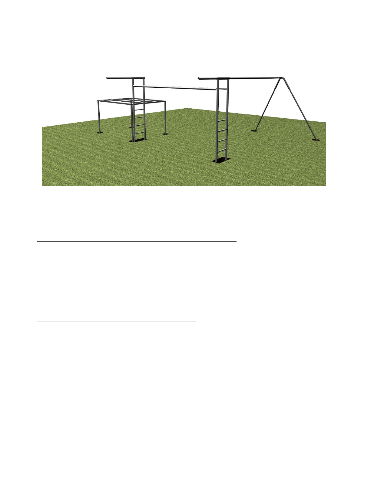
4.g. Level the Club House platform and the swing structure.
If you are assembling this structure in one day, disregard this step. When you are satisfied that the
structure is level, mix and pour the concrete according to the package directions. You will use
approximately five to seven 80# bags in the ladder hole, one to one and a half bags in each Club House
leg hole.
It is best to allow the concrete to cure at least overnight before proceeding with the installation. The next
phase will require placing heavy parts, body weight and movement onto the Club House platform. It is
important that you look at the new concrete and make your best determination as to whether or not it is
safe to continue with the next phase. Concrete will cure faster in warm conditions and slower in cold
conditions. The package directions on the concrete you buy will indicate approximate curing times. If
you are in doubt, it is better to wait longer allowing the concrete more time to cure.
The amount of concrete to be used in each hole may vary. For example: If you are installing your play
structure into a grassy area, you may want to leave the concrete about three to four inches low in the hole.
This will allow you to replace the sod and have enough depth of soil that the grass will grow the same as
before the playground was installed. As a result of this, you will use a lesser amount of concrete than
someone who chooses to fill the concrete to the top of the hole. The concrete should only be filled to the
top of the hole if you are planning to install 6 – 12 inches of soft fall ground cover. The concrete footings
should never be exposed as this presents a potential risk of injury to those who use this play equipment.
Page 23
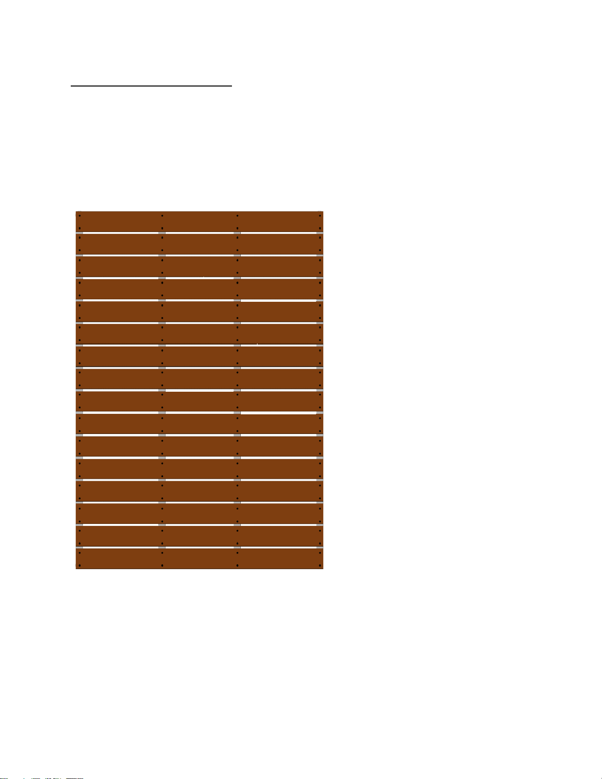
Installing the Plastic Lumber
Boards are approximately ½”
apart from each other.
5.a. With the first two boards secured into place, lay out the remaining boards onto the support
structure. Evenly space the boards as shown in the diagram shown below. Beginning at one end, it
works best to secure each board in turn using one screw at each end of the board to secure it to the
support structure, repeating this process until all of the boards are attached to the support
structure.
Page 24
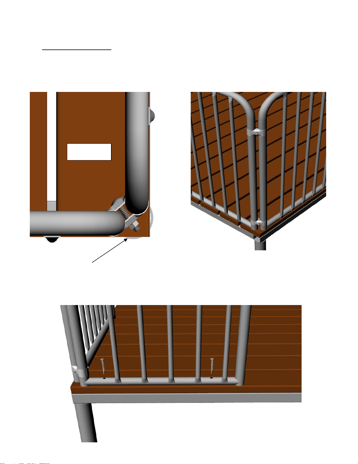
Assembling the Barriers
45 Degree angle
Top View
6.b. Secure the barriers to the platform by driving the ¼” x 2 ¾” lag screw through the predrilled holes in the bottom rail of each barrier as shown below.
6.a. Position the Barriers onto the platform and connect the corners together at 45 degree angles as
shown below. Use two of the eight sets of panel clamps with the 3/8” x 2” carriage bolt and 3/8”
hex nut that are provided at each corner.
Page 25
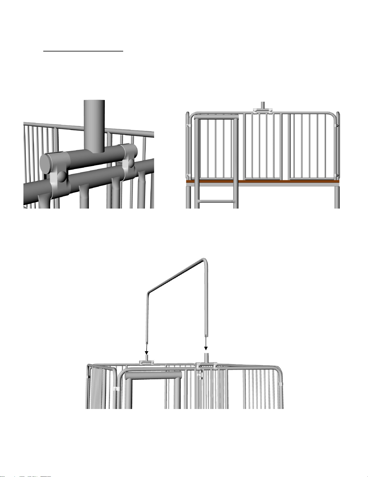
Assembling the Canopy Kit
7.b. Insert the canopy ridge pole into the brackets previously attached to the
barriers.
Note: Barrier configuration shown here is generic and does not necessarily
represent the barriers or configuration you may have purchased.
7.a. Attach the canopy ridge pole brackets to the center of both of the six foot barriers with panel
clamps as shown below.
Page 26
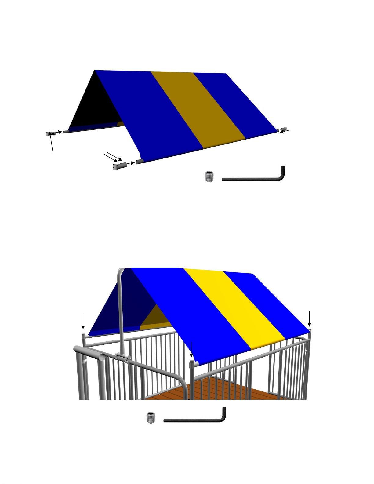
Insert the canopy side rails through the sleeves of the canopy fabric and loosely attach the barrier
Connect the barrier
attachment sockets by sliding
them onto the side rail and
loosely tightening the set
screws with the allen wrench
attachment sockets with set screws and an allen wrench
Attach the canopy side rails to the barriers and tighten them in place so that the canopy is stretched
over the canopy ridgepole tightly. (tighten all set screws firmly in place)
Page 27
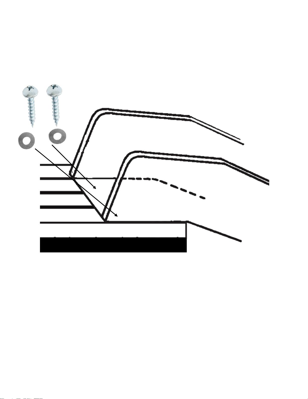
Slide Installation Instructions
Deck Mount
#14 x 1 ½””
Truss Screws
Flat Washers
Step 1: Position slide on deck in desired location
Step 2: Attach slide to deck with two #14 x 1 ½”” Truss Screws
Page 28
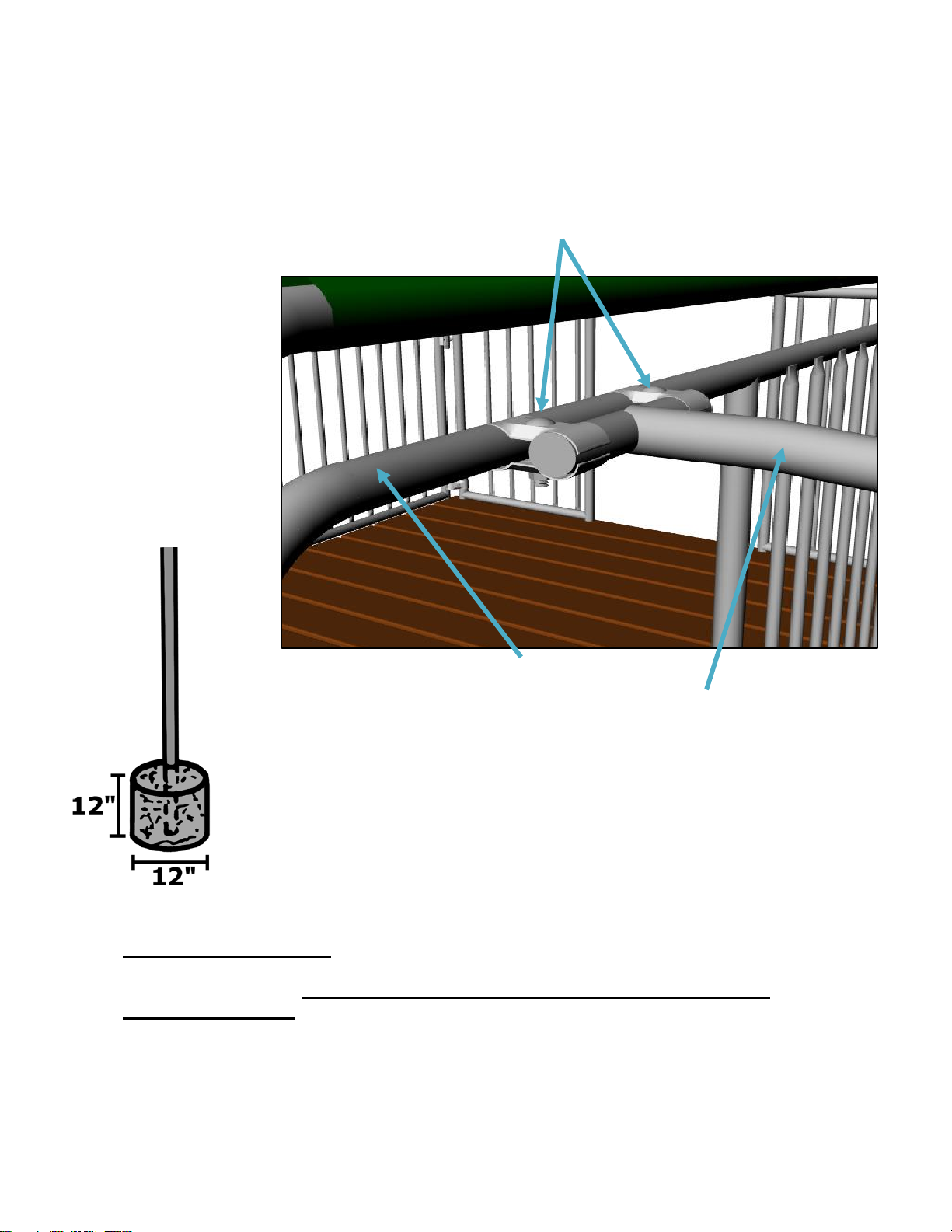
Two sets of panel clamps
with 2” x 3/8” carriage bolts
and 3/8” nuts
Dig hole 12” x 12”
and add
approximately one
80 lb. bag of
concrete mix
Fire Pole
Barrier
Double Check and Secure: Make sure to plug the open ends of the floor joist and the top rail with
the plugs provided. Double check and secure any loose set screws or nuts and bolts and enjoy your
Component Playground. Allow all of the concrete to cure completely before using your
playground. (3-5 days).
After concrete has cured, assemble and attach accessories as described below.
8.c. Fire Pole. Dig the hole for the footing about 15” away from the Clubhouse Platform and center the hole
with the desired opening in the barrier. Attach the Fire Pole to the Barrier using two sets of Panel Clamps, two
3/8” x 2” carriage bolts and two 3/8” hex nuts. Make sure the pole is level. Mix and pour concrete and allow it
to set.
Page 29
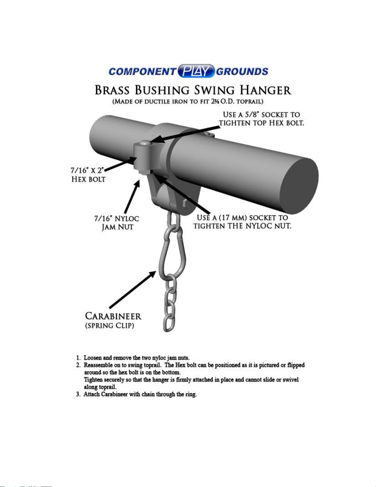
Page 30
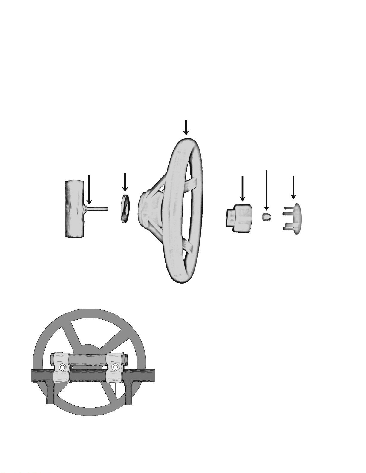
Installation Instructions
Steering Wheel
7/16”
Washer
Bracket with welded
bolt. Push two 1-3/8”
Plugs in the ends
Plastic
Pivot
3/8”
Nyloc
Nut
Pivot
Plug
Assemble Steering Wheel as
shown above. Then attach Bracket
to the Barrier with panel clamps
and 3/8” x 2” Carriage Bolts and
Hex Nuts.
©2003 Swings & Things Inc.
Steering Wheel
Page 31
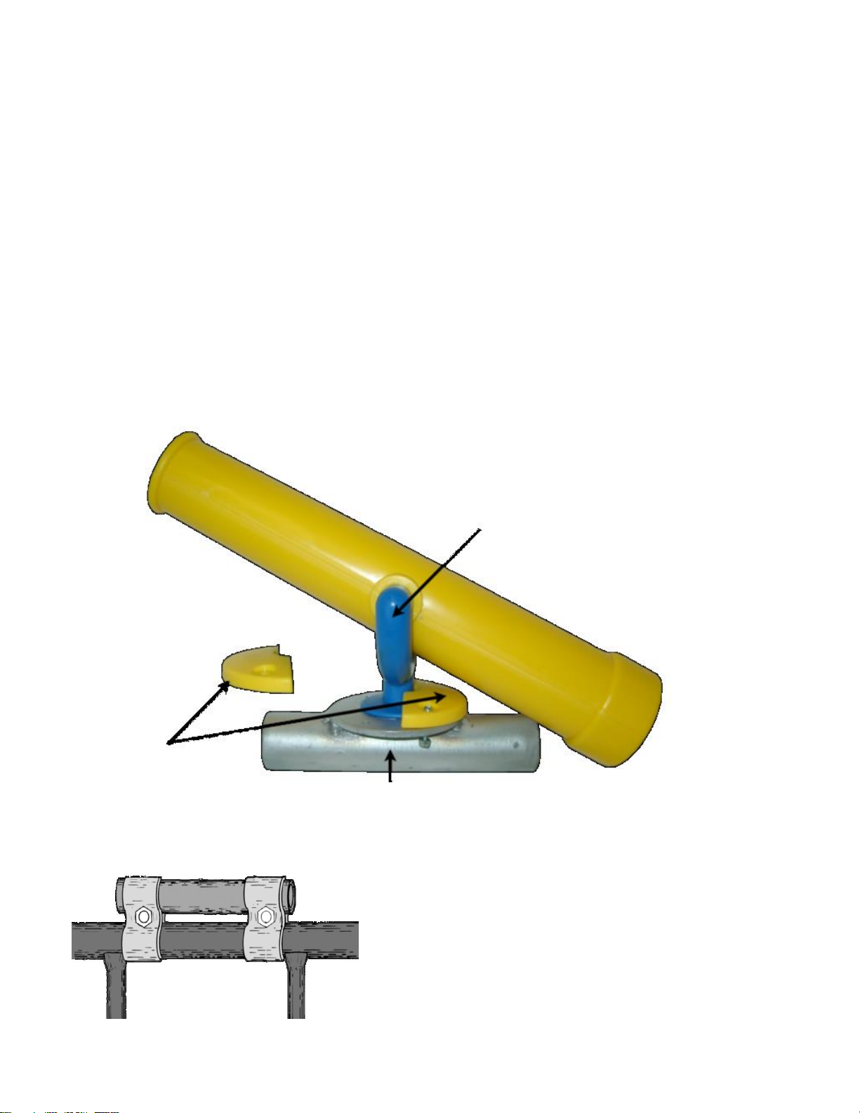
Installation Instructions
Using a small Phillips head screw driver and
a 1/4” socket.
Use 4-40 x 3/4” Machine Screws and 4-40
Nyloc Nuts to attach one side of the plastic
ring to the Bracket with welded washer.
Place the Base of the Telescope under the
lip of the plastic ring and attach the other
half of the plastic ring.
Telescope Base
Plastic Ring Halves
Bracket with welded washer
(Push 1-3/8” Plugs into both ends)
Assemble Telescope as shown above. Then
attach the Bracket to the Barrier with
Panel Clamps, 3/8” x 2” Carriage Bolts and
Hex Nuts.
Telescope
Page 32

Read Before Use
While every attempt is made by Component Playgrounds to ensure the highest degree of
safety in all of our equipment, we cannot guarantee freedom from injury. The user
assumes all risk of injury due to use. All merchandise is sold on this condition, which no
representative of the company can waive or change.
Congratulations! You have just purchased one of the finest pieces of playground equipment available.
Your family will enjoy many hours of fun with this fine equipment. Playground equipment can be most
enjoyable, but there are some dangers if not used properly. You should be aware of the following:
Equipment should be installed in a level area, free from obstructions, with enough space to allow for
adequate clearance in all directions when equipment is in maximum use.
Keep objects away from equipment that could interfere with persons using it or that could be hazardous.
Misuse or abuse of this playground equipment is dangerous and can cause serious injury.
This equipment should be inspected before each use and any worn, defective or missing parts should be
replaced.
Children should play on equipment only with adult supervision and should be duly warned of the
potential hazards in this type of equipment when used improperly. Children should be instructed as to
proper caution to take in its use.
Equipment should NOT be used when it is wet or icy.
Equipment should only be used in a well-lighted area.
Do NOT use equipment when tired, under stress or emotionally upset.
Do NOT overcrowd.
Do NOT use equipment when under the influence of alcohol or drugs.
Do NOT attempt somersaults or gymnastic stunts on or using this equipment.
Know your own limitations and exercise caution at all times.
Do not jump off of equipment when dismounting. It is a dangerous practice to jump on or off equipment.
Do not attempt to use equipment for something other than the use for which it was designed and intended,
or in a manner other than that for which it was designed and intended.
Page 33
Maintenance of your playground
We hope that you and your family will enjoy many of hours of great family fun while using your
Component Playgrounds Products. We appreciate your business. Our goal is to provide safe,
durable and fun products using the best materials available. Your product should be mostly
maintenance free. However, you should consider the following suggestions with regard to the up
keep of your new swing set.
1. Chains and Connectors: The chains are coated with the highest quality bright zinc
coating and the highest quality polymer coatings available. However, over time the zinc
coating may become discolored or eventually have surface rust appear. The polymer
coating may also become discolored with time and may eventually crack. This depends
mostly upon environmental conditions and normally will not affect the durability and
safety of the product. However, these items should be inspected regularly for excessive
wear and should be replaced as necessary.
2. Swing Hangers: These items are coated with a high quality galvanizing. However,
swing hangers may become discolored or may eventually rust. Should this happen, a
touch up using a cold galvanizing compound followed by a coat of silver aluminum spray
paint will make them look new again. These items can be purchased in aerosol cans
(“spray paint”) at most hardware stores and at Component Playgrounds. The brass
bushings inside of the swing hanger are impregnated with lubricant and will not generally
require any further lubrication. However, these should be periodically inspected for wear
and replaced as necessary. Note: Twisting the chains while swinging will put extra wear
on the swing hanger parts. If your children enjoy this practice, please inspect the swing
hangers more frequently.
3. Tire Swing Knuckles (for sets with a tire swing): The tire swing knuckle arrives at
Component Playgrounds pre-lubricated from the manufacturer. However, it is good
practice to inspect the knuckle and be sure that there is adequate lubrication before it is
used the first time. After that, the tire knuckles should be lubricated at least twice
annually to prevent excessive wear and the eventual failure of the tire swing knuckle.
4. Welds: The heat from the welding process will damage the galvanizing that is on the
pipe when it arrives to us from the manufacturer. This damage to the galvanizing is
restricted to the actual weld. When your equipment is built, Component Playgrounds will
repair this damage using a cold galvanizing compound spray along with a top coat of
silver aluminum. This is a time tested and durable process. However, when you are
inspecting your playground equipment, if you notice that some surface rust has
appeared on the welds, simply apply a fresh coat of the cold galvanizing compound and
the silver aluminum top coat to keep your structure looking new. (These spray products
Page 34

can be purchased in aerosol cans (“spray paint”) at most hardware stores and at
Component Playgrounds.)
5. Plastic Lumber Platforms: If you have purchased a structure which includes a
platform, the plastic lumber does not need to be finished or stained. It is 100%
maintenance free. However, you may need to occasionally hose it down to remove dirt
and other debris that may collect after many hours of use by happy children.
6. Vinyl Canopies: If you have purchased a structure which includes a vinyl canopy, this
product should be inspected occasionally for wear and will need to be replaced as
necessary. Depending upon your environmental conditions, the normal life expectancy
of the vinyl canopy is 3 – 5 years.
7. Swing Seats: These should be inspected at least twice annually and should be replaced
as necessary.
8. Slides: Slides should never be lifted at the bottom. Lifting the slide at the bottom will
almost always cause the slide to crack at the top where it has been attached to the
platform or bracket. Cracks and wear such as is caused by this practice are easily
identifiable and will not be covered under the product warranty.
Slides should be inspected at least annually to ensure that the sliding surface is in good
condition. Also inspect the side rails to be sure that the plastic has not been cut or
gouged in any manner which would present the risk of injury while sliding.
9. Fasteners: All fasteners should be periodically inspected to make certain that they are
tight and secure. Re-secure as necessary.
Page 35
To Help Prevent Injuries from Falls & Other Hazards
1. Never attach, or allow children to attach the following items to your swing set: Ropes, jump
ropes, clotheslines, pet leashes or any similar type of item to your swing set. Any item such as
these may present a strangulation hazard.
2. Periodically inspect all nuts, bolts, set screws, clevis, and carabineer or “S” hooks. Make
certain that these are functionally safe and secure. If you have any doubt as to the safety and
security of any connector or fastener, replace it.
2a. You should periodically check the brass bushings in the swing hangers. Look for
excessive wear in the bushing and replace as necessary.
2b. If your playground has a tire swing: The tire swing knuckle should be lubricated
twice annually to prevent wear.
3. Never allow children to wear bicycle helmets when using playground equipment.
4. Remove drawstrings from hoodie’s and jackets. Remove attached mittens and gloves. These
can become entangled with the equipment and present the risk of strangulation or other
hazards.
5. Playground surfaces can become hot in the sun. Children should be required to wear shoes
and socks when using this or any playground equipment.
6. Check for and remove sharp points or edges in the playground equipment.
7. Remove tripping hazards from the playground area. Items such as exposed concrete
footings, tree stumps, rocks or any item that may be present in your space that a child could trip
over while playing should be removed.
8. Regularly check the play equipment and the surfacing surrounding it to be certain that both
are in good condition.
9. Parental Supervision is recommended. The best ingredient for a safe playground is good
parental supervision while the kids are using the equipment.
10. Remember to play safely, take turns, share with each other and have fun!
Page 36

Residential Products
Limited Lifetime Warranty
Component Playgrounds works to build heavy duty products that will stand up to the heavy use of active
children. You can trust Component Playgrounds because of the way we design and build our products.
We make products that are simple to own, and easy to maintain. This adds up to the best value on
playground products that you can count on, and that kids will play on time after time.
Component Playgrounds warrants to the original purchaser/property owner that its’ residential grade
products are free from defect in materials and workmanship. This warranty is non-transferrable and will be
honored only after proper registration.
This warranty is not extended to cosmetic items such as scratches, dents, fading, discoloring, paint wear,
rust, weathering, or decorations. The warranty as stated is valid only if equipment is properly installed as
detailed in the installation instructions provided. All parts are subject to normal wear for the purpose of
which they were designed.
When attached to the structure, plastic slides should not be lifted up from the bottom for any reason.
Cracks at the top of the slide that result from lifting the bottom of the slide will not be covered under the
terms of this warranty.
This warranty is void should the equipment be subject to vandalism, misuse, neglect, abuse, improper
installation, tampering, or accident. This equipment is not to be altered, or modified, by anyone other than
Component Playgrounds or its authorized agent. This warranty does not cover damage resulting from
flood, fire, catastrophe or other acts of nature.
To the extent permitted by law, Component Playgrounds shall not be liable for any direct, indirect,
special, incidental, or consequential damages.
Should it be found that your product has parts that are defective within the warranty period, contact
Component Playgrounds for a warranty return authorization number. Unauthorized returns will be refused
and returned to sender. Defective part(s) must be photographed from a minimum of three different angles
that clearly show the problem, and the installation of the defective part by its self and in relation to the rest
of the structure. After obtaining a return authorization number: Return parts, freight prepaid, to the
Component Playgrounds’ plant with proof of purchase for repair or replacement. Component Playgrounds
will evaluate the part(s) and the photographs and decide if the part(s) in question should be repaired or
replaced. This warranty does not cover costs related to removal, transportation and/or labor.
This equipment is rated as commercial grade for residential use and is intended to be used in a private
residential environment. This equipment may not meet all of the safety guidelines as described by the
CPSC as it relates to public use/commercial playground equipment. For more information on public or
commercial playgrounds, please visit www.cpsc.gov.
Component Playgrounds sales representatives or its agents are not authorized to modify or substitute
claims which are not part of this exclusive written warranty. This warranty is void if the product is in any
way modified from its original state, or if it is used for purposes other than the purpose for which it was
intended.
Page 37
WARRANTY REGISTRATION SHEET
Note: To ensure your warranty is activated, complete and
return this form within 10 days of installation.
Return this form via fax to (801)530-0221, via e-mail to
[email protected], or via U.S. mail to:
Component Playgrounds
1630 North Beck Street
Salt Lake City, UT 84116
Today’s Date:_____________________________________
Sales Receipt/Invoice Number:_________________________
Model(s):_____________________________________________
_____________________________________________________
_____________________________________________________
_____________________________________________________
_____________________________________________________
_____________________________________________________
______________________________________
CUSTOMER INFORMATION
Project Name:_______________________________________
Contact Person:_____________________________________
Address:___________________________________________
City: ____________________State:______Zip:_________
Phone: ____________________Fax:___________________
Purchase Date: __________Completion Date: ____________
SALES REPRESENTATIVE/DEALER INFORMATION
(If different from manufacturer)
Organization: _______________________________________
City: _____________________ State: ______ Zip: _________
Sales Rep Name: ____________________________________
Phone: _____________________ Fax: ___________________
INSTALLATION INFORMATION
(If different from customer or sales representative)
Installed By: ________________________________________
Contact Person: _____________________________________
Address:
City: _____________________ State: ______ Zip: _________
Phone: _____________________ Fax: _____________
 Loading...