

Page 1
OPERATOR’S MANUAL
Copyright © Component Engineering, All Rights Reserved
Page 2

Table of Contents
Chapter 1: Introduction 2
Concept 2
Description 2
Chapter 2: Designing a System
What do you want to happen when? 4
Sample Program 4
Chapter 3: Installation
Mounting 6
Power Connections 6
Programmable Output Connections 10
Addendum 12
Chapter 4: Operating Instructions
Cue Application 13
The Intermission Cue 13
Running The Show 14
Maintenance 14
Chapter 5: Interlock
4
6
13
15
Description 15
Installation 15
Interlock Zones 15
Operation 15
Faults 16
External Wiring 16
Chapter 6: Interlock Rules
Chapter 7: Fire Alarm Interfacing
Chapter 8: Remote Box Installation and Operation
17
18
19
Instructions 19
MCU Chip Compatibility 19
Remove Box Jumper 19
TA-10 Selector Switch 19
Things to Know 20
Replacement of Remote Modules 21
Chapter 9: Clock Timer Operation
22
Operation Instructions 22
Chapter 10: The FM-35 Film Monitor System
Chapter 11: Accessories
23
26
Lens Change/ Douser Close Timer - Installation Instructions 26
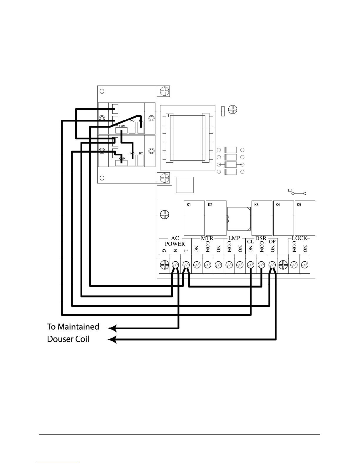
Adaptor Relay Kit for Dousers Requiring Maintained Coil Current 29
Chapter 12: Troubleshooting the TA-10 30
Chapter 13: Troubleshooting the Databus
Appendix A: Cue Assignment Sheet
33
35
Page 3

Chapter 1: Introduction
Concept
Component Engineering's TA-10 Theatre Automation System is a moderately-priced hybrid system
which uses a sequencer to perform those tasks which are the same in all programs, and a simple cue
coding scheme which allows the film itself to carry commands for other functions. There are not
many dedicated functions, but there are a lot of outputs that have not been assigned. The idea, rather,
is that the theatre’s engineer will determine the functions. It is a box full of tools with which each
individual installation can be tailored to its own needs.
Description
There are two parts to this system. One part is the sequencer and its outputs, and the other part is the
cue decoder and its outputs. The sequencer creates outputs at any of five Events, and the decoder
creates outputs from any of seven discrete cues on the film.
We shall describe the “events”, the event outputs, and then do the same for the decoded discrete
outputs.
The 5 "Events" which occur in all programs are:
1. START (when the button is pushed)
2. START plus 7 seconds
3. INTERMISSION CUE
4. End of INTERMISSION SEQUENCE
5. Film RUN-OUT
Each of these Events puts a pulse (all pulses in this system are of about 1/3 second duration) on an
output "line" to which can be connected one or more of the 6 pilot relays provided. This is done by
means of jumpers or diodes on the main circuit board. This matrix is programmed by the installer
according to the design plan for the theatre. These contacts are rated at 300mA.
There are also some fixed outputs controlled by most of these Events. These take the form of large
relays capable of handling directly the elements they are intended to control (i.e., drive motor, douser
coils, etc.). The normal operation of each of these will be described below. Things are different in
the "Interlock" mode, but that will be discussed in the appropriate chapter.
www.componentengineering.com
2
Page 4

MOTOR RELAY (K1)
This relay is energized at Event 1 and stays closed until Run-out. Its contacts are SPDT
Make/Break with all contacts brought to the terminal strip.
LAMP RELAY (K2)
This relay is energized at Event 1 and stays closed until Run-out. The available contacts are
SPST Make.
DOUSER CLOSE RELAY (K3)
This relay is pulsed at Event 1 (just for insurance) and also pulsed at Event 4. The available
contacts are SPST Make and the Common is shared with the Douser Open relay.
DOUSER OPEN (K4)
This relay is pulsed at Event 2. Its contacts are just like the Douser Close with which it shares
its Common.
INTERLOCK RELAY (K5)
This optional relay is intended for switching "Selsyn" motors or other interlock control. All units
have this socket, but the relay is installed only on request.
UTILITY RELAY (K6)
This relay can serve several purposes. It comes connected as a "Show Running" relay. As such,
it is operated at Event 2 and released at Event 4. (In other words, it energizes when the Douser
opens and releases when the Douser closes.) Its contacts are SPDT Make/Break with all elements
available. (Possible uses would be such things as dousers, which require maintained current,
exciter lamp switching, etc.)
By means of a strapping change on the circuit board this relay can be used as a "Show End" or
"Motor Off" relay. In this mode it will pulse at Event 5, and might be used to release the selflatching circuit of a motor contactor. Other configurations will be discussed in the design section.
INTERMISSION SEQUENCE
This is a user determined time interval, which begins with a cue from the film, and ends when the
time interval has elapsed. The interval is set by means of DIP switches on the Micro Controller
Unit (MCU) plug-in assembly. The dip switches are discussed later.
CODED CUES
Up to 7 different discrete cues can be put on the film, each one of which has its own output. The
7 outputs are possible because of the FM-35 Cue Detector which incorporates a sensor capable of
reading 3 different cue patches on the film. The trick is to not think of them as three cues, but to
think of them as the elements of a 3 bit binary code. This means that from combinations of the
three cues on the film, there are 8 possible outputs (or "states"). One of these "states" is 0, which
leaves 7 more for us to use. All of these outputs pulse pilot relays. The contacts are rated at 300
mA.
DATA LINK
Multiple TA-10 systems can be tied together via a standard 2 conductor shielded cable. This
feature allows the connected TA-10s to talk to each other and/or a central control and monitoring
station. Also, this is how 2 or more houses are run interlocked with each other.
These are the tools. The next step is to design your own system.
www.componentengineering.com
3
Page 5

Chapter 2. Designing a System
What do you want to happen when?
Write out the most complicated program you are likely to have to run, but do it in two columns. One
column will show those things which will always happen at the same point in the program, and the
other column will show those things which are governed by the film. Now, while checking the list of
"Events", give each of the "always the same" entries an "E" number.
Next, referring to the sample on the page that follows, you will assign "Q" numbers to the list of cues
that are governed by the film. There are however a few things to consider. It is a good idea to try to
make the most frequently used cues the ones that are easiest to apply. Try to save the edge-only cues
for those functions, which might have to be triggered while the picture is on the screen. Don't get too
fancy. You have only 7 cues and one has to be reserved for "Intermission".
At this point you need to know more about the "Intermission" cue. This cue is used for several
purposes besides beginning the Intermission Sequence. It all depends upon where you are in the
program. After the douser is open and the show is running, triggering "Intermission" will begin the
Intermission Sequence as you would expect. After the douser has closed, but the film has not run out,
another "Intermission" cue will re-start the show by initiating the normal 7 second Start Sequence.
Those who like to put a “Curtain Call” in their program can use this feature. It also can be used when
making a lens change. See "Operating Instructions” for more on this Cue.
After you have made your choices, you can go back to your list and fill in the "Q" numbers. Please
see the next page for a sample list with all the assignments made. Note that the dedicated functions
are not listed.....only the user defined ones.
You can see how it works. The standard parts of the show are controlled by the events, but the midshow changes are controlled by the discrete cues. For this example, it has been decided that the house
standard is to Mute the Non-Sync at show start, so this function is tied to an Event (E1) rather than a
Cue. It is also tied to another Event (E4) at the end of the show.
As most trailers now are in a Stereo format, we save cueing by using E2 to bring in Stereo Sound.
(Mono Sound can be called for by Q2.) If there is a mono trailer or Logo, a Cue will have to be
added.
As both the event relays and the “Q” relays are double pole relays, functions that are always
preformed together can be wired to the separate poles of the same relay. The following example
assumes a dimmer system that allows for half-light, which is triggered by E1. Q3 takes them down
the rest of the way, while Q4 will bring them back to Half during the closing credits.
Note: There are bound to be needs not provided for in this system, and others, which may well be
possible but not outlined in these instructions. If you have questions or are not sure how to attain
your design goals, please call us at (206) 284-9171 and let us try to help.
www.componentengineering.com
4
Page 6

Sample Program
Lights to Half E1
Mute Sound E1
Stereo “A” E2
(Previews now on screen)
*
Lights Down Full Q3
SR/Digital sound Q7
(Feature now on screen)
Light to Half Q4
Intermission Q1
Mute Sound E4
Non-Sync Sound E5
* Should you have a lens changer you might add the following after the previews:
Curtain Call Q1
Lens Change Q6
End Curtain Call Q1
In summary:
The Cue assignments are: The event relays are:
Q1 Intermission Mute Sound
Q2 Mono Stereo “A” Sound
Q3 Lights Down Non-Sync Sound
Q4 Lights to Half Lights to Half
Q5 Stereo “A” Lights Up
Q6 Lens Change
Q7 SR/Digital sound
Q1 was used for "Intermission" because it is probably needed more than any other, is easy to put on,
and is easy to trip manually.
Q2 for Mono is admittedly in the picture area, but sound cues tend to be applied on or near the headend splice where it is likely to be black.
Q3 is another, which is probably going to be placed in the black between the end of a trailer and the
beginning of the feature.
Q4, on the other hand, is most apt to be wanted just before the start of the closing credits where it
might show on the screen.
Q6 is another, which will be used when the screen is dark.
www.componentengineering.com
5
Page 7

Chapter 3: Installation
Mounting
MAIN ASSEMBLY
The main circuit board, its relays, and the control panel, are produced in two different formats. In
addition to the self-contained wall mount unit, there is a mounting package for use in consoles.
FM-35 CUE DETECTOR ASSEMBLY
Please refer to Chapter 10, FM-35 Film Monitoring System.
Power Connections
INPUT POWER
The actual power requirements for this unit's own operation is small. Note that the fuse is 3/16
amp at 110 VAC (1/4 Amp at 110 VAC if you have the “clock” version). Therefore, 18ga. wire
would be sufficient as long as the insulation is adequate. Observe the "HOT" and "NEUTRAL"
terminals, as well as the "GROUND", which is connected to the chassis. A "ring" type of
terminal and a lock washer should be used under this screw.
If not already connected, the wiring to the power switch and fuse are merely plugged into the
mating connector on the circuit board. This connector is polarized and can't be plugged in
incorrectly. The wiring harness for the manual control switches is likewise simply plugged into
the 9-pole receptacle on the relay circuit board. This plug is also polarized.
MOTOR RELAY
Wire the motor hot lead through this relay with the power source to the "COM" terminal and the
motor to the "N.O." terminal. The manual switch on the control panel is wired in parallel with the
relay contacts for emergency operation. In most cases, only the "Make" contacts of this relay will
be needed, but the "Break" contact is also available for those who, for example, like to switch
their "Non-Sync" Off and On this way. Power will be fed out the "N.C." terminal when the relay
and the manual switch are Off. There are simple ways to modify the motor control circuit to
accommodate projector motors that are switched by a contactor requiring only momentary
control. Contact Component Engineering for details.
LAMP RELAY
Wire the remote switching circuit from your lamp to the "COM" and "N.O." terminals.
DOUSER RELAYS
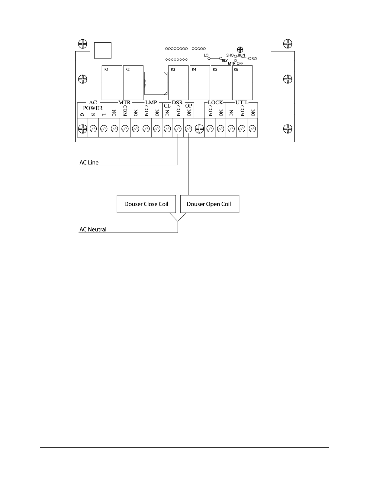
The contacts of the two relays are interconnected such that the input power hot lead should go to
the "COM" terminal and the two douser coils then connected to their respective "OPEN" and
“CLOSE" terminals. Power Neutral goes to the douser coil common. An accessory board is
available for maintained dousers. (See Chapter 11, Accessories.)
www.componentengineering.com
6
Page 8
INTERLOCK RELAY
The primary purpose of this relay is to energize a "Selsyn" when that type of interlock system is
employed. By breaking a circuit board trace, however, it can be strapped for other purposes.
These options are described below. While the socket is in all units, the relay itself is installed
only upon request.
UTILITY RELAY
As originally wired, this relay is a "SHOW RUN" relay. That is, it energizes on Douser Open,
and releases on Douser Close. Possible uses might be for rotary solenoid types of dousers, which
require maintained current, or for installations that like to switch their Exciter Lamp Off and On.
If manual control is desired it must be wired parallel with external wiring as there is no “built in”
provision for manual control of the Utility Relay or outputs.
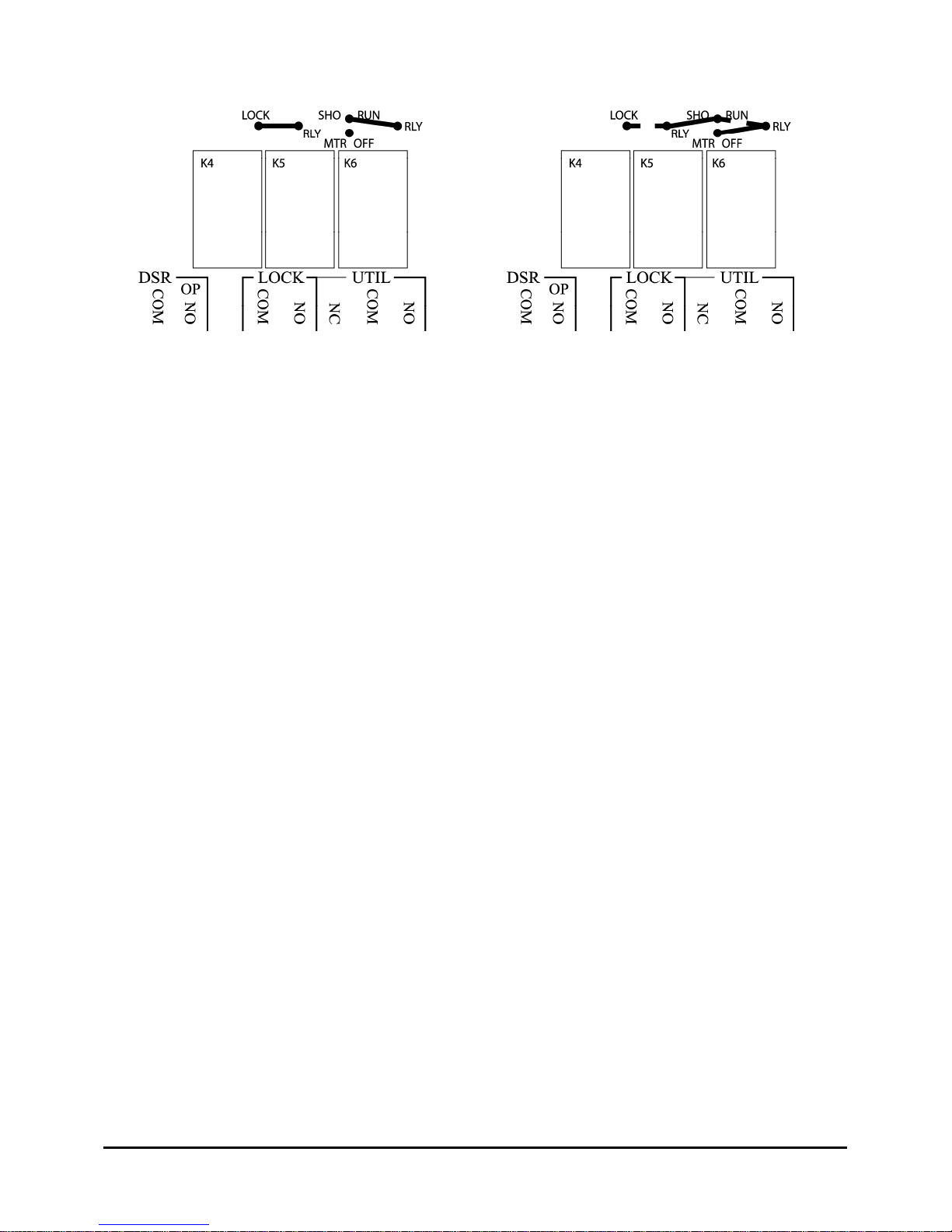
Referring to the following figures, you can see that by cutting a circuit board trace and installing a
jumper wire, this relay can become a "Motor Off" relay. This is intended for those projectors
whose motors are switched by a contactor, which has a self-latching circuit. By using this relay's
"Break" set of contacts, the contactor latching circuit can be interrupted. Note also that the figure
that follows shows how both the "Utility" and the "Interlock" relays can be reassigned.
www.componentengineering.com
7
Page 9
CONTROL CABLES
The cable from the Push Button Control Panel is terminated by two plugs, which go onto headers
at the top of the main circuit board. These headers are just above the plug-in Micro Control Unit
(MCU) subassembly.
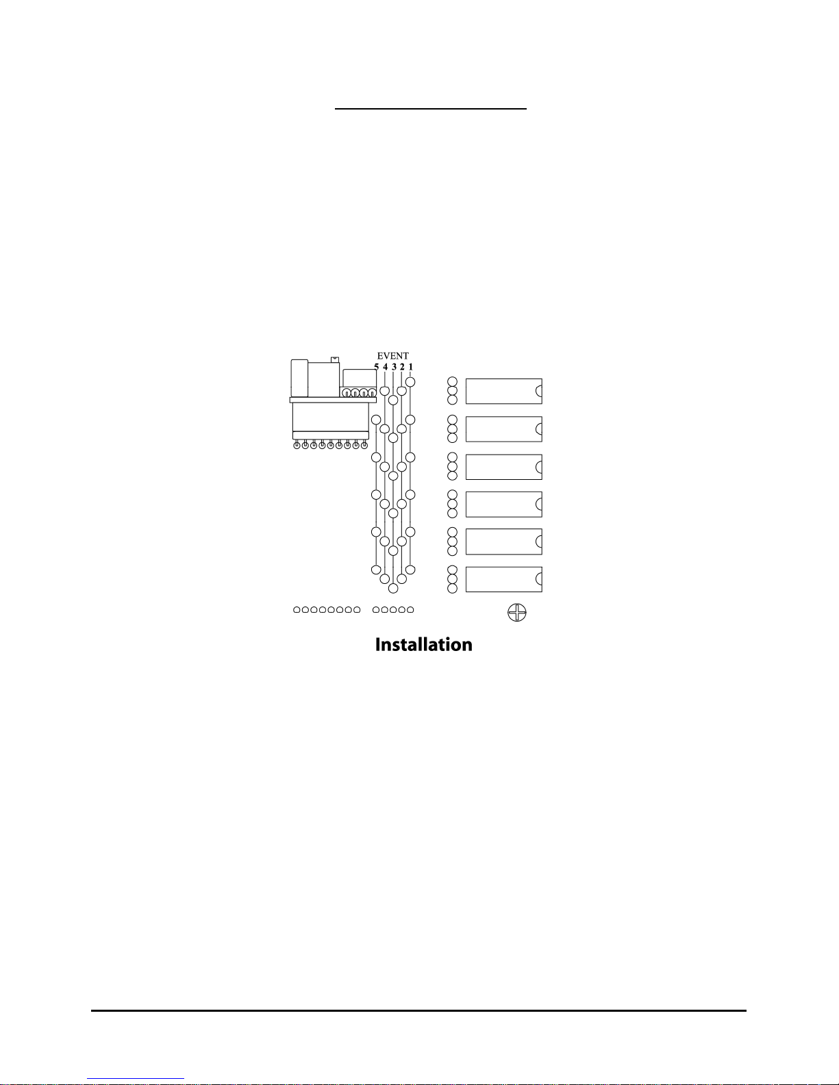
The "Intermission Cue" wires come connected to "Q1", but if your system design calls for a
different Cue, they can be relocated.
The 15-conductor cable from the FM-35 cue detector assembly is terminated in the strip on the
left side of the main board. The terminals are marked with the color code matching the
conductors in the cable.
Note: For ease in installing and/or servicing this unit, Film Presence and Film Motion defeat
switches are provided. These are the small switches immediately to the right of the lower end of
the FM-35 terminal strip.
DATA LINK
Any TA-10 Theatre Automation system can communicate with any other TA-10 and/or a Remote
Control Station, via the "Data +" and "Data -" connections. See the figure that follows. This is an
RS-485 bus, which is capable of operating over fairly long distances, and is quite immune to
noise. This link is particularly useful in that it is the only interconnection required between units
operating in the "Interlock" mode. ("Selsyn" interlock systems obviously have to have their own
5 conductor interconnecting wiring.) Standard 2 conductor shielded wire (such as you would use
for audio wiring) is recommended. Be sure to observe and maintain the polarity. Unlike audio
wiring, both ends of the shields must be terminated to chassis ground.
Depending upon the length of the electrical ground runs and the tightness of wire and conduit
connections, there is the possibility of a voltage difference between the grounds of any two
chassis. Therefore, before actually connecting the second end of a shield to the ground terminal,
it is wise to check for voltage between the unattached shield and the ground terminal.
If there is any voltage indicated, a 47 to 100 ohm resistor should be soldered on the end of the
shield with the other end of the resistor going to the ground screw.
www.componentengineering.com
8
Page 10
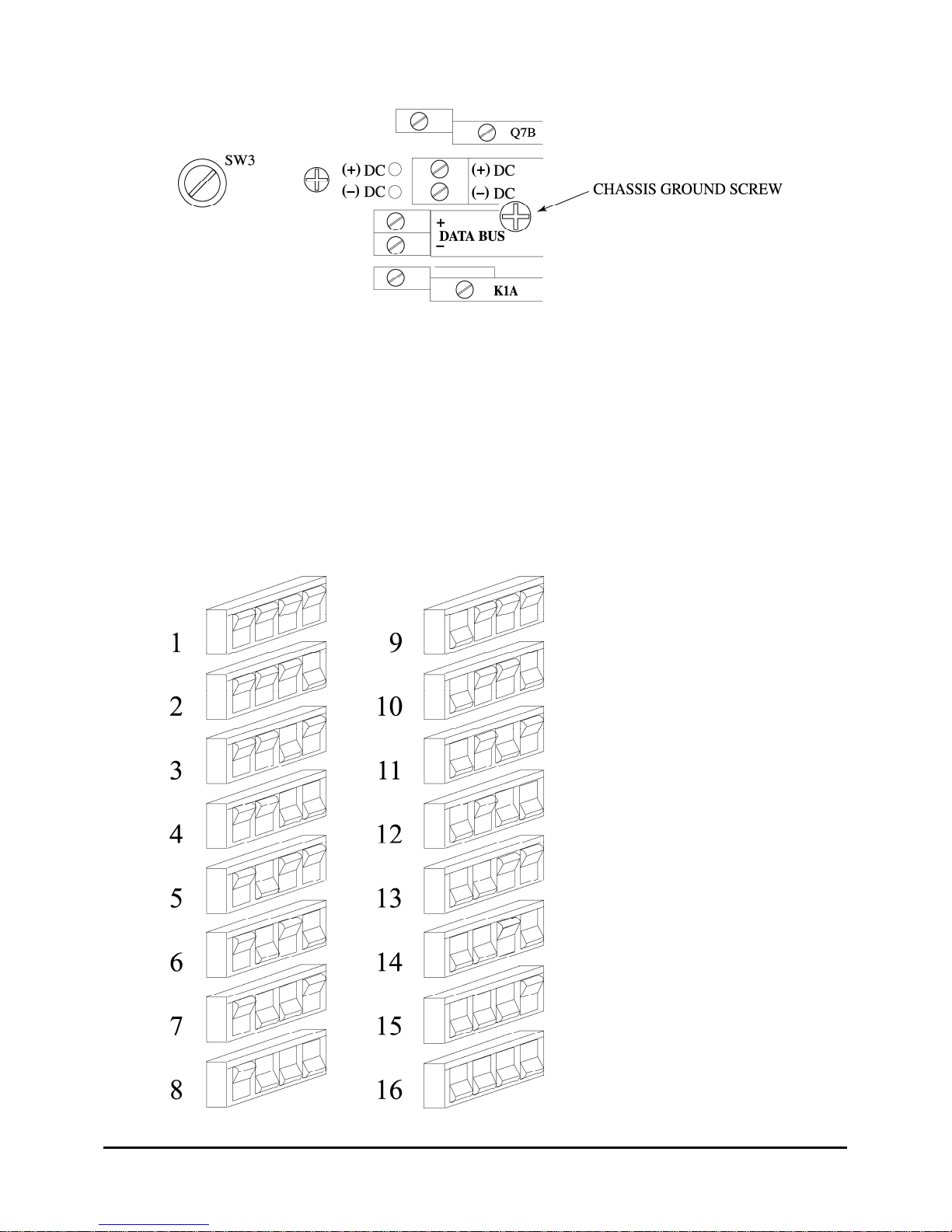
For reliable operation, the RS-485 data bus protocol requires that the bus be properly loaded. The
normal recommendation is that the load be about 75 ohms with half of this load at the extreme
ends of the run. Every TA-10 has a switchable 150-ohm resistor installed so that no external
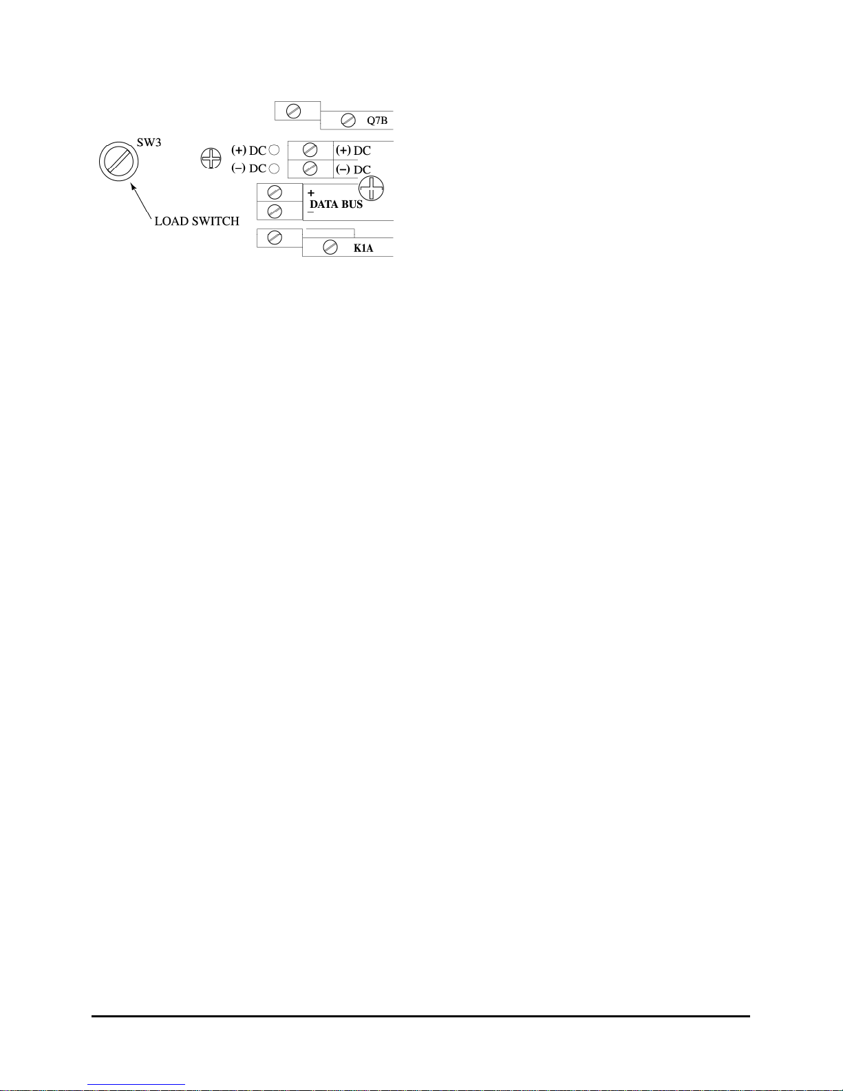
resistors are needed. The switch that does this is SW3 (indicated on the drawing above), which
looks like a screw head on a short black plastic stud. When the screw is down, two leads are tied
together, and when the screw is backed out a half turn or so, the circuit is opened.
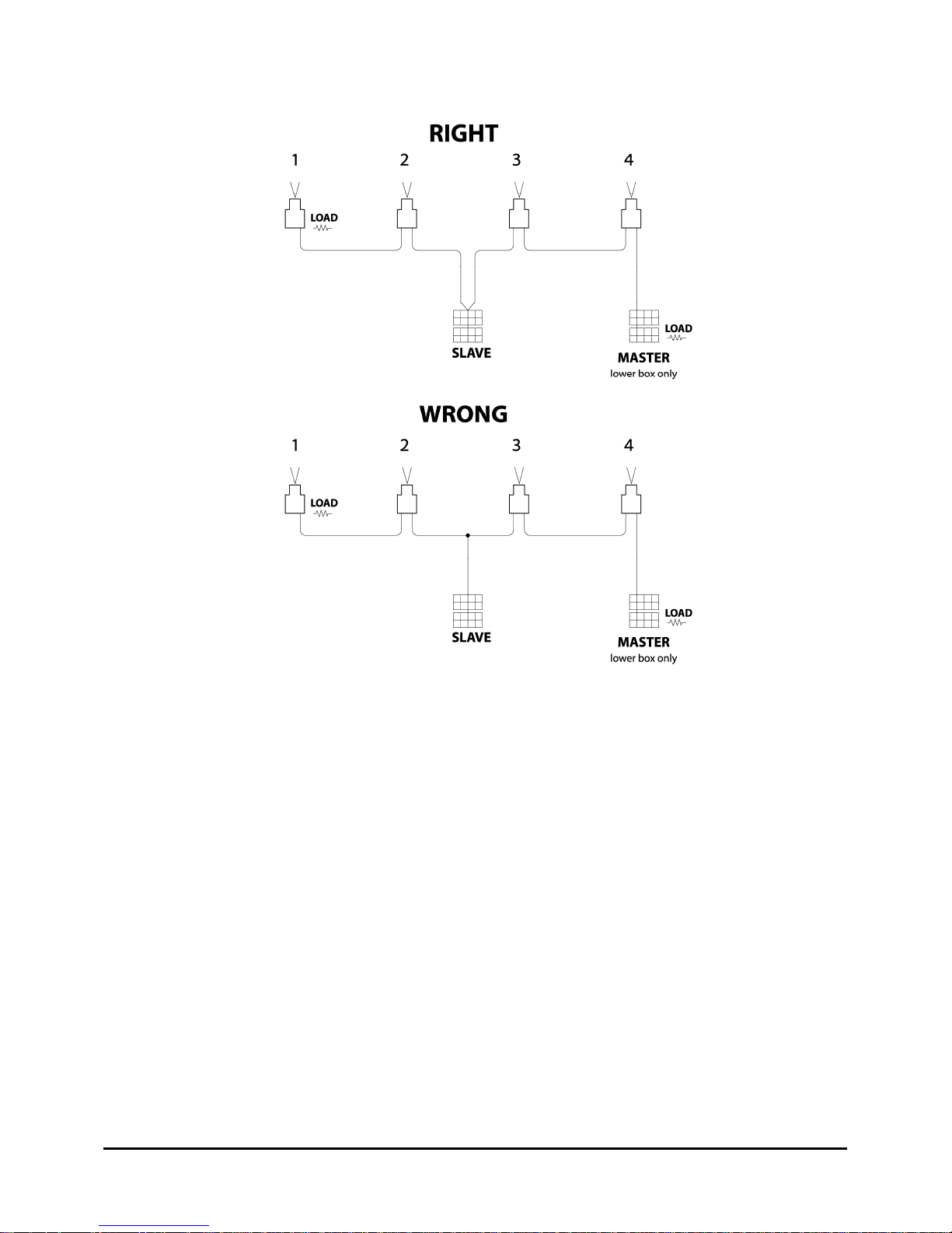
When installing the data bus make sure that all screws are backed out (switch open) except those
at the ends…. be it a TA-10 or a Remote Box. This will leave two 150-ohm resistors across the
data bus for a total parallel load of 75 ohms. It is a good idea to check the bus with an ohmmeter
(with all units powered OFF) to confirm.
When two or more TA-10s are tied
together via the Data Link, it is
essential that each one be assigned its
own discrete address or the various
units will confuse each other.
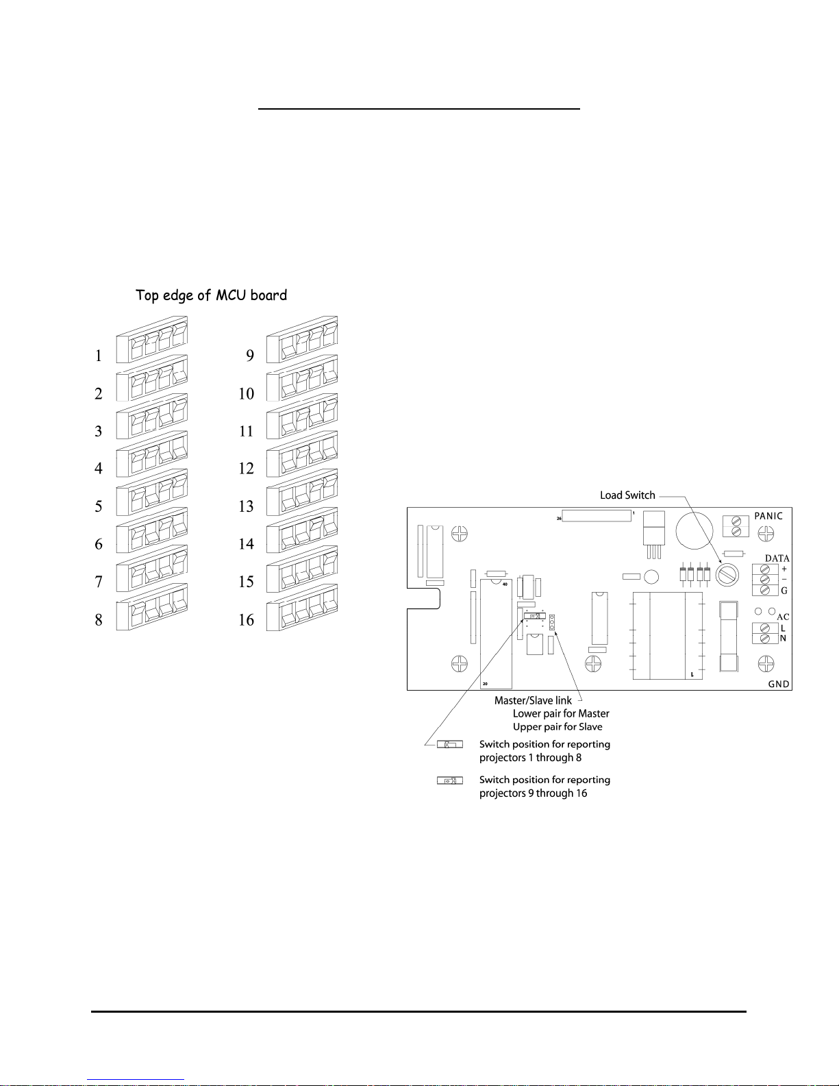
This address is set by means of the 4
pole DIP switch in the upper left corner
of the MCU circuit board. (The MCU
board is the small circuit board, which
plugs into the main circuit board.)
The figure on the left will show you
how to set the switches for each of the
sixteen possible assignments. The
important thing is that no two of them
are alike.
All TA-10s and remote boxes are wired
in series, there can be no tees. You
must have the one remote box that is
enabled as “master” at one end of the
bus.
www.componentengineering.com
9
Page 11
REMOTE CONTROL
The Remote Control system connects to the individual automation through the RS-485 bus.
Using the terminal strip in the upper right corner of the TA-10 board can configure a hard-wired
control of “Start”, “Stop”, and “Interlock”. Connecting the ground terminal and the appropriate
terminal is all that is required. The "Start" function could be connected to a timer and the "Stop"
could be connected to an in-house system for "Panic" shutdown. (It is often connected to a Fire
Alarm system.) A Cue could be used to have the system shut itself down.
Programmable Output Connections
OUTPUT RELAYS
All of the programmable control outputs (either the Cues or the Events) from this automation are
by means of pilot relays. Their contacts are rated a 300 mA. ac, or 1 Amp dc. The relays are
closed for approximately 1/3 second. Circuit voltages of more than 48 are not recommended.
As normally installed, each relay has 2 sets of “Make” contacts brought out to the terminal strips.
If “Break” contacts are needed, one set can be had by unplugging the relay, moving it one position
to the right and reinstalling it. Now, the top pair of contacts will still provide a “Make” set of
contacts, but the lower pair of terminals will provide a “Break” set of contacts. These can be used
independently of each other, or wired to form a single SPDT contact set.
www.componentengineering.com
10
Page 12
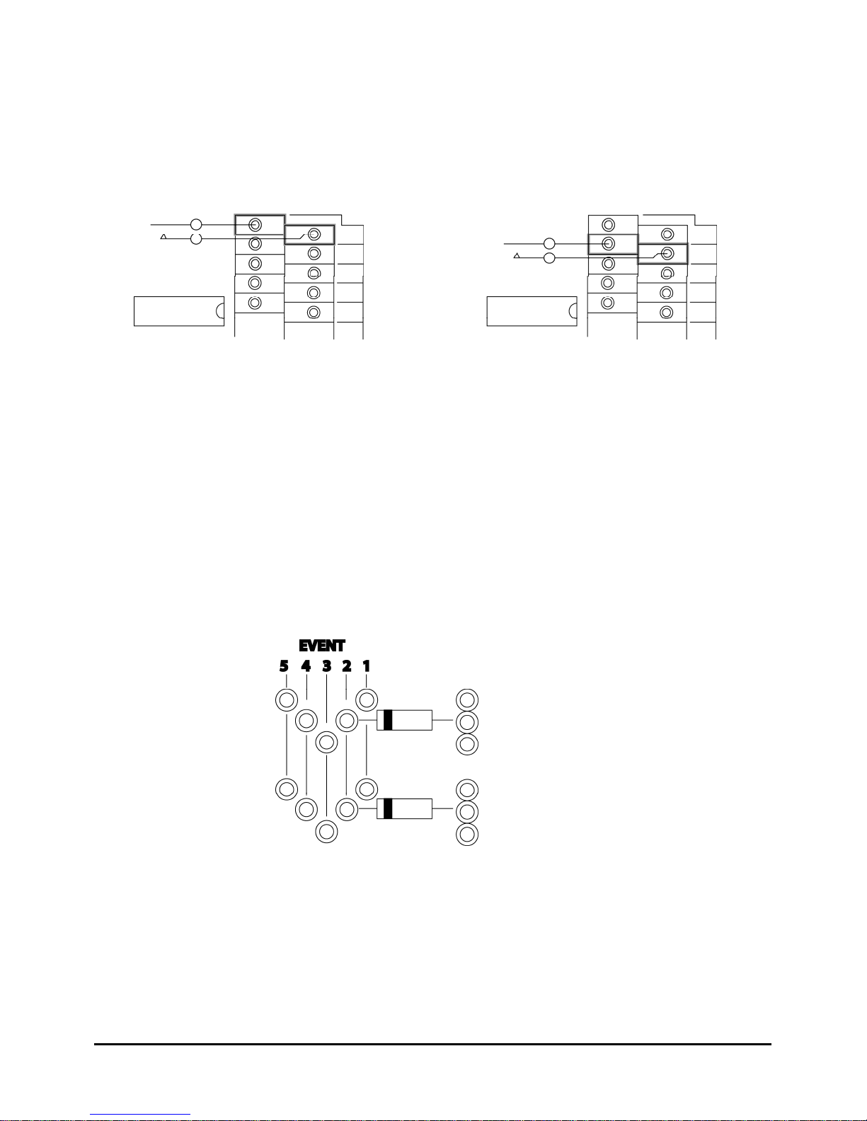
This illustration will show you how to wire to each of the contact sets. The left figure shows the
terminals for one set of contacts. The right figure shows the terminals for the second set. The
pattern just repeats for the rest of the relays, and is the same for either the Cue relays or the Event
relays.
PROGRAMMING THE "EVENT” RELAYS
To have a relay operate from an Event, you put a jumper from the hole associated with that Event
over to one of the three holes provided for each relay.
IMPORTANT: If you want a relay to be operated by more than one Event, you must use
diodes instead of plain jumpers! Use any general-purpose diode you like as long as it is rated at
1 Amp or better. The Cathode end points to the left as indicated by the symbol printed on the
circuit board.
Note: Soldering these jumpers can be done from the top of the circuit board as long as you are
careful to not let the lead ends go down through the holes too far.
www.componentengineering.com
11
Page 13

INTERMISSION SEQUENCE
The time interval between the Intermission Cue and the Douser Close (Events 3 and 4) is
determined by the installer. On the top of the small circuit board, which is plugged into the main
board, there are 2 DIP switches. The six-pole switch is the one we want here. The six individual
switches are arranged in a binary format such that the left switch is 1 second, the next one is 2
seconds, the third is 4 seconds, and so forth until the sixth switch, which is 32 seconds. Just
decide how many seconds you want for your Intermission Sequence and flip switches until they
add up to the number you have chosen. (For example, if it takes your curtain 11 seconds to close,
flip the 4th switch [8 seconds], 2nd switch [2 seconds] and the 1st switch [1 second] for a total of
11 seconds.) If you don't flip any, the system will default to 7 seconds.
Addendum
MANUAL CONTROLS
Manual controls for motor, lamp and douser are provided on the front panel. These switches are
in parallel with the power relays and thus will operate the device in question even when the TA10 is off. These are the only assigned outputs and as this system is designed to give the user
flexibility, it is difficult to provide manual override switches for such things as dimmers, curtains,
masking or the like. The need for such manual switches, however, is real. Therefore, six
unassigned switches have been provided which the installer can assign and wire as desired.
A selection of labels is also provided with which to identify these switches. The panels are
normally loaded with two SPDT maintained contact switches, and four SPDT center off
momentary switches. Other configurations may be had upon request. .187 X .032 push-on
terminals are required for connection to these switches and a supply comes with the unit. When
installing these terminals be sure to put a hand against the outside of the switch as its plastic
retaining springs may not be strong enough to withstand the force necessary to seat the terminal
on the lug. If more terminals are needed, please be sure that they are meant for the .032"
thickness of the male lug. The .187 X .020 terminals have the potential of ruining the switch if
they are forced onto the lugs.
DEFEAT SWITCHES
"Film Presence" and "Film Motion" defeat switches are provided for ease in working on the
system. These are small slide switches located on the main circuit board immediately inside the
lower portion of the terminal strip to which the FM-35 cable is connected. These switches
parallel the relay contacts of the FM-35. The front panel LEDs will come on and serve as a
reminder that the switches have been operated.
www.componentengineering.com
12
Page 14
Chapter 4: Operating Instructions
Cue Application
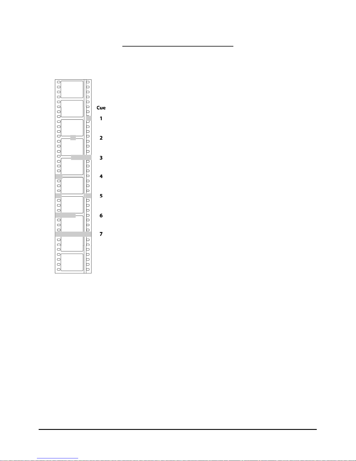
The foil cue patches required for this system are simply little pieces of 3/16"
or 1/4" wide aluminum foil tape. The illustration shows how each of the
individual cues should look. This diagram shows the multiple position cues
as single pieces of cue tape because they are easier to apply, but discrete
patches could be used. Remember that any cue in the center position is in the
center of the film, not the center of the picture area.
You may perforate the cues with your splicer if you like, but it really isn't
necessary. The foil may be put on either the emulsion or the base side of the
film, and you can even seal it in with a piece of splicing tape. In some cases,
a good location is right under the splice between two parts of your program
(such as between the trailers and the feature). This is particularly effective
for sound change cues and helps remind you to remove the cues when you
break down the film.
All of the patches for a given cue should be on the same frame line. The
decoder can tolerate some linear displacement, but if you are off more than
about 1 frame they will not be read correctly.
The decoder can handle only one cue at a time, but successive cues can be
placed as close as 1 foot apart. (Using the same example of the transition
from trailers to feature, you might have a Stereo Sound cue under the splice
and a Lights Down cue 1 foot earlier.) If, continuing with our example, you
also have to add lens and/or masking change cues, consider making up
already cued standard slug leaders that you can cut into your program as
needed.
The Intermission Cue
This is a busy cue. True, its primary purpose is to initiate the Intermission Sequence, but it does other
things as well, depending upon where you are in the program.
Suppose your program calls for a "Curtain Call" (or "Mini Intermission"). As you come to the end of
the trailers, put on a regular Intermission Cue just as you would at the end of the program, but in this
case the film is not going to run out and stop the projector. 7 seconds before you want the next part of
the program to appear on the screen, put another Intermission Cue on the film and it will behave just
like pushing the Start button.
One of the dangers of the above scheme is that after the Intermission Sequence has timed out and the
douser has closed, the system thinks that it is at the end of the show and is looking for Run-Out so
that it can shut down the motor. This means that the alarm is disabled, and so, if you have a film
break during your "Curtain Call", you won't know it.
www.componentengineering.com
13
Page 15

If you don't want to trust to luck, there is an answer, and it is the Intermission Cue again. If you put
on still another Intermission Cue before the douser closes, (1 foot after the first cue is a good place)
the alarm will be reenabled. Once the show has re-started itself, everything will be normal.
This cue is also used to Start the show when you are in Interlock. The "Interlock" section will discuss
this feature in greater detail.
Running The Show
You can pretty well monitor the status of your program by observing the lights in the indicator
column on the control panel. The red light at the top shows that the system is On. When the film is
threaded and ready to run, the Film Presence light will come on. When the Start button is pushed, the
motor and lamp will be turned on, the Motor On and the Lamp On lights on the panel will light up,
the Power On light will start pulsing to show that the program is running, and the normal 7 second
Start Sequence will begin. Shortly thereafter, the Film Motion light should come on, and at the end of
the 7 seconds as the douser opens, the Show Running light will come on.
If you push the Start button when the film is not ready, the alarm will sound for as long as you hold
the button down.
If, during running of the show there is a film break or a loss of film motion, the alarm will sound and
all Intermission functions will be activated. Pushing the stop button will silence the alarm. After you
fix the problem, push the Start button and you will go through a normal 7-second sequence. You will
want to check the status of any program changes that might have been made earlier in a normal show
(such as Sound format, House Lights, etc.) and re-establish them manually.
During the Start Sequence there is a 3 second bobble delay during which the Film Presence detector is
disabled to allow for settling of the film handling machinery.
Film Motion monitoring begins after this same 3 second point.
Maintenance
The only maintenance required is to the mechanical parts of the FM-35 detector assembly. Please
refer to Chapter 10, FM-35 Film Monitoring System.
www.componentengineering.com
14
Page 16
Chapter 5: Interlock
Description
If you have read the prior chapters, you have a pretty good idea of how the TA-10 handles the
interlocking of two or more projectors. This chapter will bring it all together.
Any two or more projectors on the same Data Link can communicate with each other for purposes of
running in unison. The mechanical means by which the projectors synchronize with each other is up
to you, be it synchronous motors, Selsyns, or bicycle chain. If needed there is a relay, which will help
you with the control of your part, but you may have to add some extra circuitry. More about this
later.
Installation
Please review the data bus wiring recommendations in Chapter 3, Installation, pages 9 and 10.
Interlock Zones
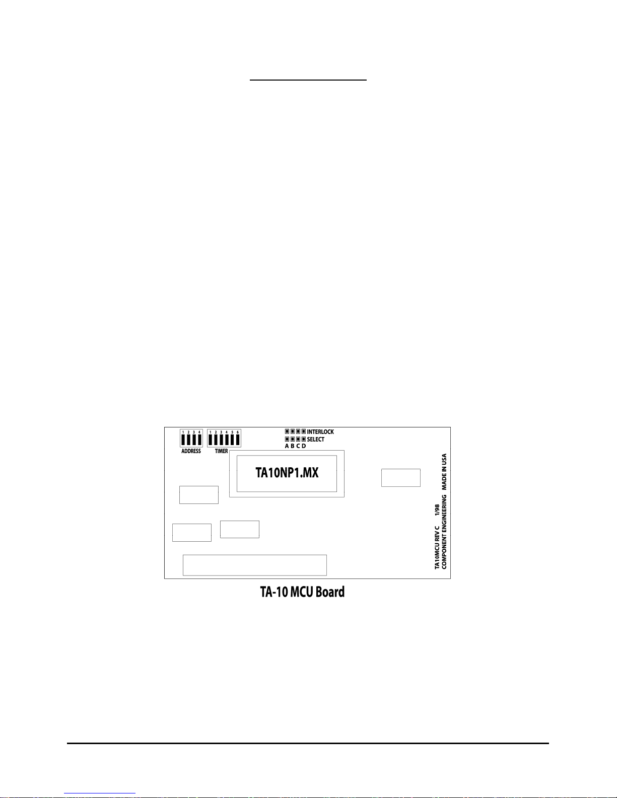
Each TA-10 MCU board can be set for zones A,B,C, or D. If you have permanent interlock groups
you would set the links as necessary. If your groups will change with conditions we recommend that
you install a rotary selector switch on the front panel and wire it to the pins. We will supply the
switch and connector upon request.
Operation
A "run-through" of a typical presentation might be the best description. Thread up each projector as
you would for any Interlock presentation, and when it is ready to go, push the "Interlock" button on
the control panel. The bottom blue lamp on the control panel will light.
www.componentengineering.com
15
Page 17

Then go on to the next projector, thread it, push its "Interlock" button and so on. When all machines
are ready to go, push any "Start" button and all machines will roll together.
Because they are in the Interlock mode, only the motor relays will operate when the "Start" button is
pushed. Each system is waiting for something to tell it when to start the rest of the show, and that
something is the Intermission cue. When the cue arrives at each projector in turn, each will begin its
normal 7-second cycle starting the show.
As the show is running, all Events and Cues will happen normally. At the end of the Intermission
Sequence (Event 4) on a given projector, faults will no longer be transmitted on the Data Link
because that particular system is looking for a Run-Out. When the film does run out, that one
projector will shut down as usual, and drop out of Interlock. Any other machine still on the bus will
continue normally.
Faults
If a projector in the Interlock mode receives a Start command from the Data Link, and is not ready to
go, it will immediately put a Stop command back onto the Data Link and sound its alarm. Likewise,
at any time during the show, a loss of Film Presence or Film Motion will cause a Stop command to be
transmitted to all other projectors in Interlock. Each will shut down and trigger their Intermission
functions, and the alarm on only the initiating projector will sound so that you know where the trouble
lies.
In this case, because you are presumed to be in midshow, and the projectors will remain in the
Interlock mode. This means that when you next push the Start button, each machine will start up and
go immediately into the 7-second start cycle. It won't be looking for a Start Cue. If any of the
systems on-line have been taken out of Interlock and then put back in, they will assume that it is a
new start and will look for a Start Cue.
In this case, it would probably be best to toggle all of the projectors out of Interlock and then back in,
and then go around and manually trigger each of them after restarting. As is the case with any stop
caused by a fault, you will also need to manually reestablish some things such as sound format and
house light level.
External Wiring
If you are using synchronous motors, there is no need for any other wiring. You don’t even need K5,
the Interlock Relay. However, if you are using Selsyn Interlock, the Interlock relay can be used to
energize the individual Selsyns which you will have connected together by the required 5 conductors.
If you are tying together no more than two projectors, the easy way is to wire the 117 V.A.C. to the
Selsyns through both of the Interlock relays in series. If, however, you are putting more machines on
the bus, then you may want to add a three-pole relay for each Selsyn motor. If you switch (via the
interlock relay) only the excitation voltage to the Selsyns, in many cases there will be enough induced
current from the secondaries to cause them to sort of try to follow each other. So, if you install a three
pole relay such that you switch not only one leg of the primary circuit, but two of the secondary legs
as well, each unit will be fully isolated from the others. The Interlock relay would be used to operate
this three pole auxiliary relay.
www.componentengineering.com
16
Page 18

Chapter 6. Interlock Rules
Be sure the Blue Button has been pushed and the "Interlock" light is on for all projectors you want tied
together.
When in "Interlock", pushing the START button will start only the motors. The system will now be
looking for an Intermission Cue, which will initiate the rest of the start sequence.
Once the show is running on all screens, a failure on any one of them (or pushing the STOP button) will
cause all to shut down, but remain in "Interlock".
When starting in this mode, the systems will go right into a full start sequence. Any projectors that have
been taken out of "Interlock" and re-entered, will again be looking for an Intermission Cue.
When the show is running, the Intermission Cue reverts to its original function and will trigger the
intermission sequence.
After the intermission sequence (the show is off the screen), the system will no longer recognize a failure
on that projector, but is looking for run-out at which time the motor will stop and that machine will drop
out of "Interlock".
DO NOT turn off the A.C. power to any TA-10 that is operating in INTERLOCK. A TA-10 that is
not “ON” cannot send fail/stop codes to the remaining TA-10s that are interlocked with it. The other TA10s will not fail/stop in this circumstance until a film break occurs.
www.componentengineering.com
17
Page 19

Chapter 7: Fire Alarm Interfacing
The only real need for connection between the TA-10 and a Fire Alarm System is for an automatic
shutdown triggered by the alarm system. Provision is made on the main circuit board of the TA-10 for
external control of the "Stop" function, and if you are using the Remote Box there is a "Panic" input
available, which will stop all TA-10s on the data link.
In the upper right corner of the TA-10 main circuit board there is a four pole terminal strip. These
terminals parallel the manual push buttons and allow for external control of "Start", "Stop" and
"Interlock". The fourth terminal is "Ground". Connecting "Ground" to any of the others will call that
function. When connecting the "Stop" function to the Fire Alarm system it is best to do so by means of
relays. One tidy way of doing this is to have the alarm system give you a low voltage pulse (or
maintained*), which is connected to the coil of a small relay at each TA-10 location. SPST Normally
Open contacts on the relay are then connected to the "Stop" and "Ground" terminals on the TA-10. The
control line from the alarm system and the TA-10s can then be just one line running from one unit to the
next. Relays would be selected to match the voltage available from the alarm system, and they can be
small as the current required to operate the "Stop" circuit is 25 mA. or less.
A second scheme would be to put multiple contact relays at the alarm system location and then each TA10 would have to have a home run to that location. In such a case, each TA-10 should be connected to its
own set of contacts on the controlling relay(s). The idea is to try to keep the Grounds of the various TA10s separated just to prevent any possible cross-talk or interference problems.
If Remote Boxes are wired into the system, the "Panic" capability can be used. Inside each Remote
Box is a two pole terminal strip labeled "Panic". When these two terminals are connected an immediate
code is put on the data link, which will instantly initiate a "Stop" at each TA-10. Please note that this
method will not work if the Remote Box is not turned on. If this scheme is used it is wise to have the
Remote Box powered from the same (or similar) uninterruptible circuit as the alarm system.
* A maintained "Stop" command will have to be released before the projector can be re-started. The
system will try to start, but will immediately stop again. When the "Stop" command is received by the
TA-10, whether it comes from the data link, an external contact closure or from a finger on the "Stop"
button, several things happen simultaneously. The Motor relay is released, the Lamp relay is released, the
Douser Close relay is pulsed, the Show Run relay is released, and Event lines 3 and 4 are pulsed. This
means that the projector itself is shut down with its lamp off and the douser is closed just to be sure.
Then, all functions tied to all of the normal End-of-Show sequences are triggered. You should have all of
the lights fading up, curtains closing, and sound muted.
www.componentengineering.com
18
Page 20

Chapter 8: Remote Box Installation and Operation
Instructions
IT WON'T WORK if you do not follow the instructions.
9 You must have the right controller chips in both the TA-10 and the Remote Box
9 You must have the wiring exactly right
9 You must have the address switches in the TA-10 set correctly
9 You must have the switch that selects which range of TA-10 addresses to monitor, set
correctly.
9 You must have the master/slave link correct in the Remote Box
9 You must have the load switches set properly
MCU Chip Compatibility
As of this writing we are shipping the “TA10NP-2” in the TA-10, and the “REMNP-2” in the full
function Remote Box. The “REMNP-2A” is in the status only Remote Box. In each case the chip in
question is the large 40-pin integrated circuit. In the TA-10 this chip is on the small plug-in board at
the top of the main circuit board perpendicular to the main board. In the Remote Box it is the largest
chip on the lower board. Other versions of these two programs will not work together.
Remote Box Jumper
Any remote box can be configured to be either a “Master” or a “Slave”. Only one (1) remote box on
any data link can be the master. The advent of the 16 TA-10 bus with 2 gang boxes does NOT
change this rule. Only one individual box can be configured as the Master. All other remote boxes
on any data link must be slaves or chaos will result. Look at the lower circuit board in the Remote
Box, just to the right of the large 40-pin integrated circuit there is a small jumper on two of the pins of
a three-pin header. If the jumper is connecting the lower pair, then it is the Master. If the jumper is
connecting the upper pair, then it is the Slave. (Actually, the jumper is not needed at all for Slaves, it
is merely stored in the upper position.)
Remember, only one Remote Box per data link can be a Master. How do you decide which one is the
master? It has been found that the best choice is the one at the end of the line. In other words, the one
at the end of the longest cable run. Usually this will be the one downstairs in the box office or in the
manager’s office. There will be confusion on the line if the master is in the middle trying to send
information requests out in both directions.
TA-10 Selector Switch
The Switch that selects which TA-10s will be monitored is located above and to the left of the
master/slave link. If the slide is to the left it is 1-8. To the right is 9-16.
www.componentengineering.com
19
Page 21
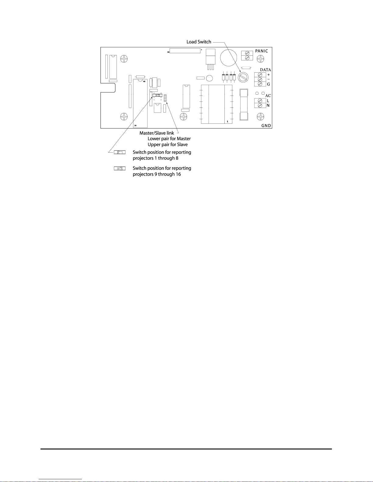
Location of Remote Box selector switches.
Things to Know
The lamp indications at the Remote Box are as follows:
No lights = no film in projector
Red light on steadily = film threaded and ready
Red light flashing = seven second start sequence running
Green light on steadily = show running
Green light flashing = intermission/stop sequence running
Blue light on steadily = projector in Interlock
Red and Green lights flashing = failure
None of the pushbuttons on the Remote Box will do anything unless the "Enable" button is held down
simultaneously. The "Enable" button is the black one in the upper right-hand corner. If there is a
failure at any projector the Red and Green lights for that unit will flash and the alarm will sound. To
silence the alarm push the "Enable" button and the appropriate "Stop" button. The lights will continue
to flash until the alarm at the projector is silenced. Canceling the alarm at the Remote Box does not
cancel the alarm at the projector. If the projector alarm is canceled first, however, the Remote one
will soon stop.
Projectors in Interlock cannot be started from the Remote Box. It is felt that to do so would be a little
too risky. Interlocked units can be stopped remotely.
Because this data link has to handle the traffic from not only the Remote Box, but any projectors in
Interlock as well, a time-sharing arrangement is employed. Failure information is given top priority,
action commands come next (i.e., "Start" or "Stop") and then at approximately two-second intervals,
if nothing else is going on, the Master Remote Box polls each of the projectors for a status report.
This means that in some cases the indications at the Remote Box may lag a little behind what is
actually happening at the projector, but it will catch up within less than two seconds.
www.componentengineering.com
20
Page 22
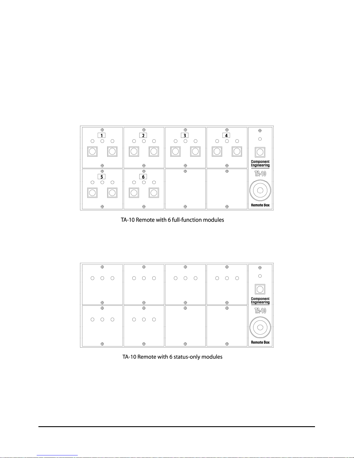
Placement of Remote Modules
The position of the remote module in the Remote Box determines which TA-10 address it will
respond to. In a Remote Box configured for TA-10s 1-8, the top left position is for the TA-10 with
address #1. The bottom right is for address #8.
In a Remote Box configured for TA-10s 9-16 the top left is for TA-10 with address #9 and the bottom
right is for address #16. The numbered stickers can be placed anywhere that you wish.
www.componentengineering.com
21
Page 23
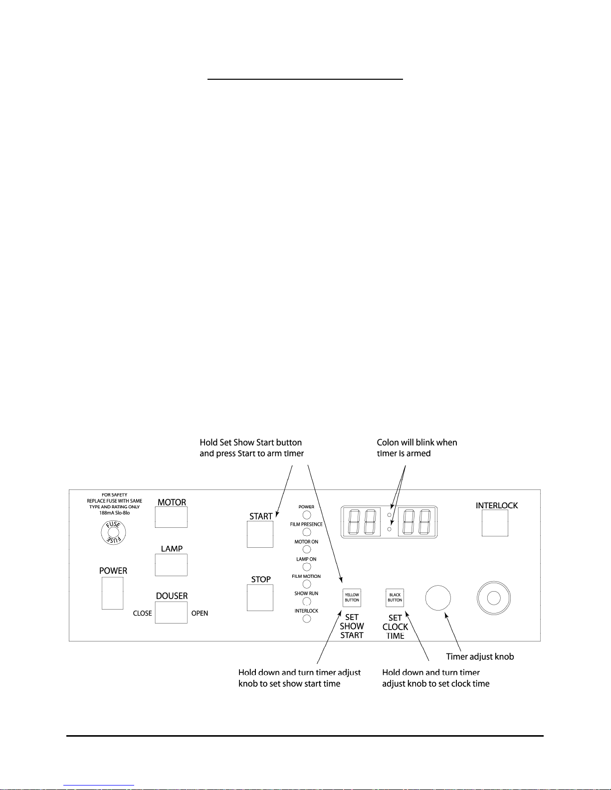
Chapter 9. Clock Timer Operation
Operation Instructions
Using the Auto-Start clock is really very much like an ordinary bedside digital alarm clock. It tells
you what time it is and it lets you select when you want it to wake you up. The Auto-Start timer does
exactly the same thing except that it starts the show instead of waking you up.
When you power up the system for the first time, you will need to set the clock for the time of day.
Press the small black push-button and hold it down while you rotate the knob until you get to the
current time. The knob can be rotated in either direction so that you can either advance or retard the
reading. The clock will now keep time even when the unit is turned off, for as long as several days.
Setting the Auto-Start Time is just as easy. This time you press the yellow button and turn the knob
to the time at which you want the show to start. When you have set the show start time you next must
arm the system. This is done by first pressing the same yellow button and holding it down while you
press the large green start button. When you release both buttons the colon in the clock will be
flashing to indicate that the system has been armed and will start automatically when the appropriate
time is reached.
Should you wish to cancel the automatic start you can do so by first pressing and holding the yellow
button and than pressing the stop button. Upon release the colon will no longer be flashing and the
system will not start automatically.
If you are operating in the Interlock mode, the automatic start is not allowed—the beeper will sound
to warn you that you can’t do that.
www.componentengineering.com
22
Page 24

Chapter 10. The FM-35 Film Monitoring System
The FM-35 is a self-contained unit (except for power supply) which consists of a three-position proximity
sensor type cue detector, film presence (i.e., film break) sensor and a film motion sensor. The unit is
furnished with a multiconductor cable with a connector at the detector assembly end. Also furnished is a
mounting bracket which sandwiches in between the take-up arm and the bottom of the sound head.
(Special mounting arrangements may have to be devised for projectors not made in the U.S.)
The unit requires from 12 to 30 Volts D.C. either from the host automation system or other power supply.
If the host system is A.C. operated it takes only a bridge rectifier and a single filter capacitor to get the
necessary D.C. If the input is 12 Volts, use a 25 Volt capacitor in the range of 470 to 1000 mFd. From a
24 Volt source, use a 50 Volt capacitor in the 33 to 100-mFd range. Maximum momentary current drain
is 400 mA. Ready-made power assemblies are available for some automation systems, and there are walltransformer type power supplies which can do the job.
The cue detectors are for inboard, center, and/or outboard cues. For purposes of standardization and
customer convenience, all units are equipped with all three detectors. These are of the "ECKO" (Eddy
Current Killed Oscillation) proximity type and will respond to small foil cue patches on the film. The
recommended size of the patch is approximately 3/16" to 1/4" square. Please see the attached illustration
for placement. Note that the center cue is placed in the center of the film, not the center of the picture
area. Should you have any trouble with these small cues rubbing off, they may be sealed in by overlaying
them with a piece of clear splicing tape, or in some cases be installed on a splice line under the tape.
The film presence (film break) detector is actually two detectors scanning the two edges of the film. This
is done with infrared light and is therefore not visible to the eye. If there is film properly seated over the
black roller a green LED will light and the relay will close. The film motion detector is similar except
that it is watching the two rows of perforations. When the film gets up to about half normal speed its
motion will be sensed.
All outputs are relay contacts rated at 500 mA. The three cue detector outputs are "Make" (Form "A")
contacts, while the Film Presence and Film Motion detector outputs are "Make/Brake" (Form "C")
contacts. The contact identification on the cable color chart/block diagram sheet shows the unthreaded
condition, i.e., no film in the projector. The cue detector output pulses are stretched to about 1/3 second
(350 to 400 milliseconds). Should a longer pulse be required, successive cues can be placed on the film at
6 frame intervals. Each cue will re-start the 1/3-second interval.
Little or no maintenance is required other than keeping the optical assemblies clean. The Film Presence
and Film Motion detectors operate by shining infrared light onto the film and then detecting the light
when it is reflected back. If the LEDs from which the light comes, or the phototransistors, which receive
it, get too dirty, the detectors cannot work. In a normal cleanly maintained projector it is usually
sufficient to merely wipe the optical area with a clean dry cloth.
If you find an excessive amount of dust, lint, or film wax accumulating, it would be a good idea to check
the alignment of the film path through the unit. If the alignment is not correct the film will scrape on the
roller flanges and create debris, which can be deposited on the optical sensors.
www.componentengineering.com
23
Page 25
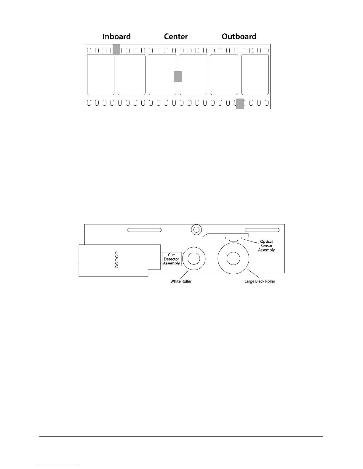
Also, watch for too much oil. If this is combined with the dust problem, a sort of "mud" is produced
which may require stronger cleaning measures. Stay away from the more exotic solvents such as acetone,
MEK, or that thing which have "chloro" or "fluoro" in their names. These (and others) have the potential
of attacking the plastics in the sensor assemblies, which could ruin them and require their replacement.
If it is time for a real bath, remove the large black roller and then remove the two small Phillips head
screws which hold in the optical assembly. With the screws out the whole assembly can be unplugged by
pulling it straight out. Spray the sensor area thoroughly with one of the stronger household cleaners such
as "Formula 409", "Texize" or the like. Allow the detergent to work a minute or two and then scrub it
with a toothbrush. Then rinse it off with a strong stream of hot water. If it does not look clean, do it all
again. Dry it all off and put it back together.
www.componentengineering.com
24
Page 26
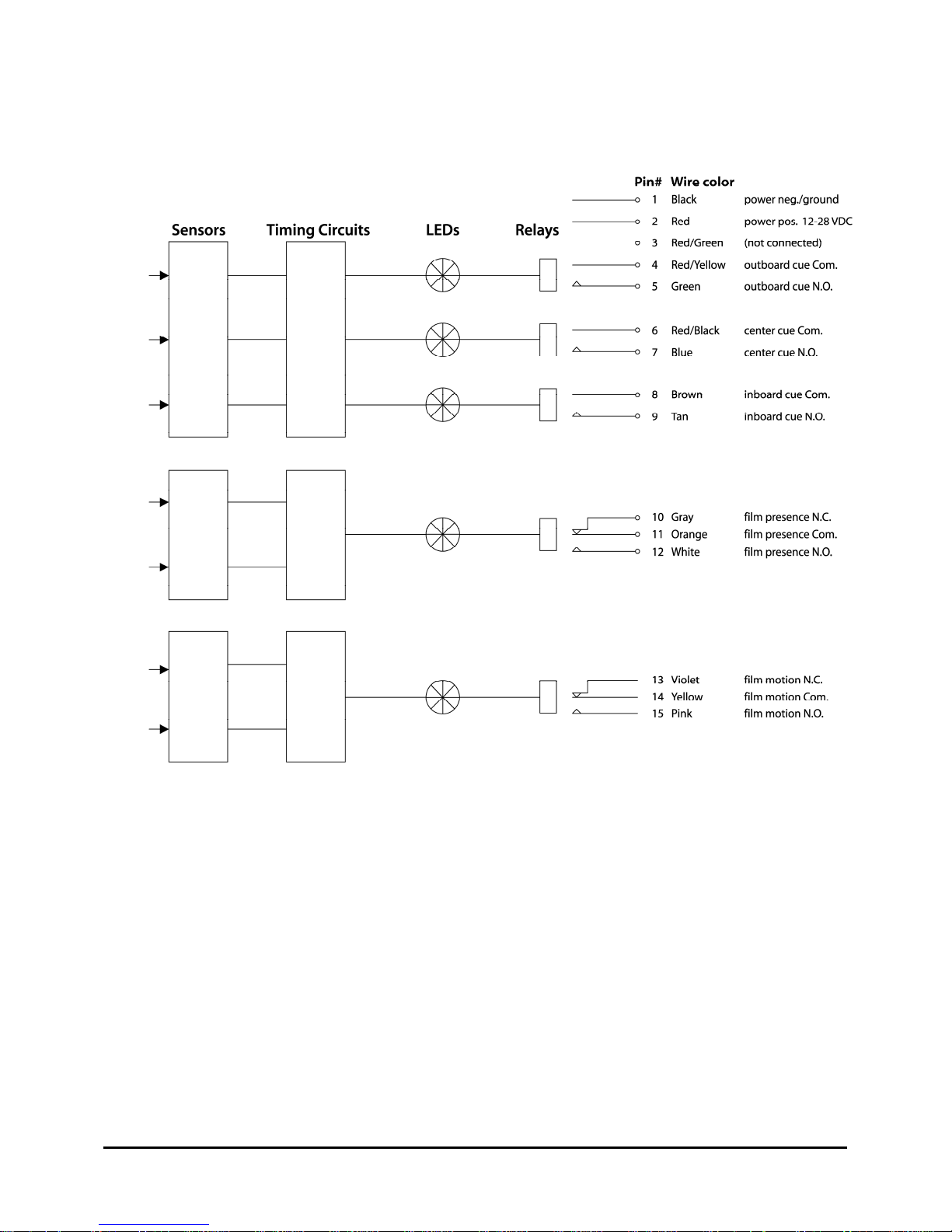
FM-35/37 block diagram with wire colors and pin numbers
www.componentengineering.com
25
Page 27
Chapter 11: Accessories
Lens Change/Douser Close Timer - Installation Instructions
The purpose of this device is to close the douser during the rotation of the lens turret and re-open the
douser after a predetermined time period. The device can be programmed for use with either the
normal dual-coil douser, which is operated by current pulses, or with the maintained type of douser
control. The closing of the douser is initiated by whichever cue commands the lens turret to start. An
adjustable timer is also started which re-opens the douser at the end of its cycle.
The unit mounts by means of a connector, which plugs into a header, which in turn is to be installed
on the main TA-10 circuit board.
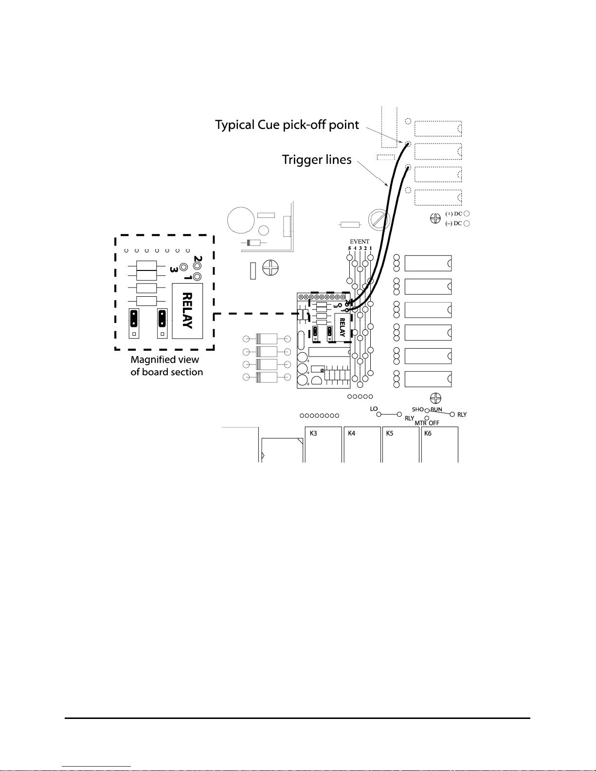
In the upper right corner of the timer board are three pads labeled “1”, “2”, and “3”. Number “3” is
not used for this purpose. Numbers “1” and “2” are the input triggers and they are identical. If you
wish to be able to go both from “Flat” to “‘Scope” and “‘Scope” to “Flat” you will need both inputs.
If, however, you return your turret to “Flat” during the intermission, you will need only one input and
it can be either one.
Connect a short (4” or so) piece of wire to one or both inputs. The other end will go to whichever cue
you have assigned to start the lens turret. Rather than connecting to the cue relay contacts, however,
we will connect to the coil side of the relay thus saving all the contacts for external controls (such as
masking). The drawing shows the location of the cue relay coil connections and it is to one of these
that you need to solder the input wire(s). It is easier to get your soldering iron in there if you unplug
some of the cue relays. This is the only wiring required.
www.componentengineering.com
26
Page 28
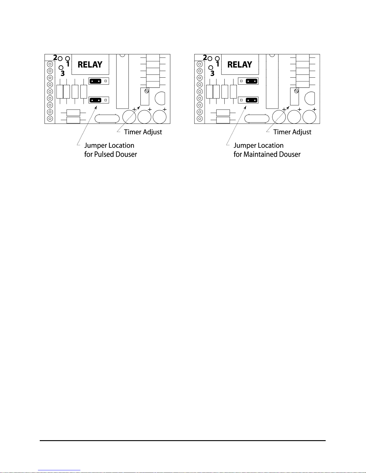
Check the location of the programming links with the illustration. See the notes below if you are
using the maintained style of douser.
The adjustment of the timer is mostly a “set and try it” proposition. With the machinery running,
initiate a lens change which will also close the douser and start the timer. Note when the douser
opens again and adjust the timer to suit. Turning the timer control counter-clockwise will shorten the
time. You are finished!
Notes related to maintained dousers: If your system is using the “Utility” relay for this purpose you
need to move over to the “Douser Open” relay. Use the “DSR COM” and “OP NO” terminals.
Operation will be exactly the same as it is now. If you have a wire connecting from the “Show Run”
solder pads on the board over to one of the small pads above the large relays and already have your
douser connected to the “DSR OP” terminals, you need to remove this wire as it will now be replaced
by the circuitry in the timer board.
www.componentengineering.com
27
Page 29
www.componentengineering.com
28
Page 30
Adaptor Relay Kit for Dousers Requiring Maintained Coil Current
www.componentengineering.com
29
Page 31
Chapter 12: Troubleshooting the TA-10
www.componentengineering.com
30
Page 32
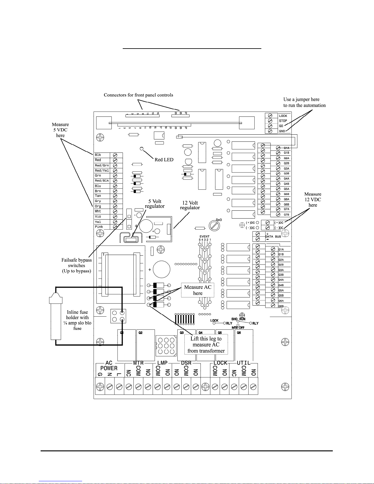
This is how to test a TA-10 main board. These instructions should be done after you have checked all the
connections to the board, the power fuse, and you have swapped MCU boards and FM-35s with another
TA-10.
First, unplug all the cables. Also, remove the douser timer board and anything else that is powered by the
12VDC terminals on the main board. Any fire alarm connection to the STOP and GND terminals in the
upper right hand corner of the main board must be disconnected. Measure the resistance of the primary
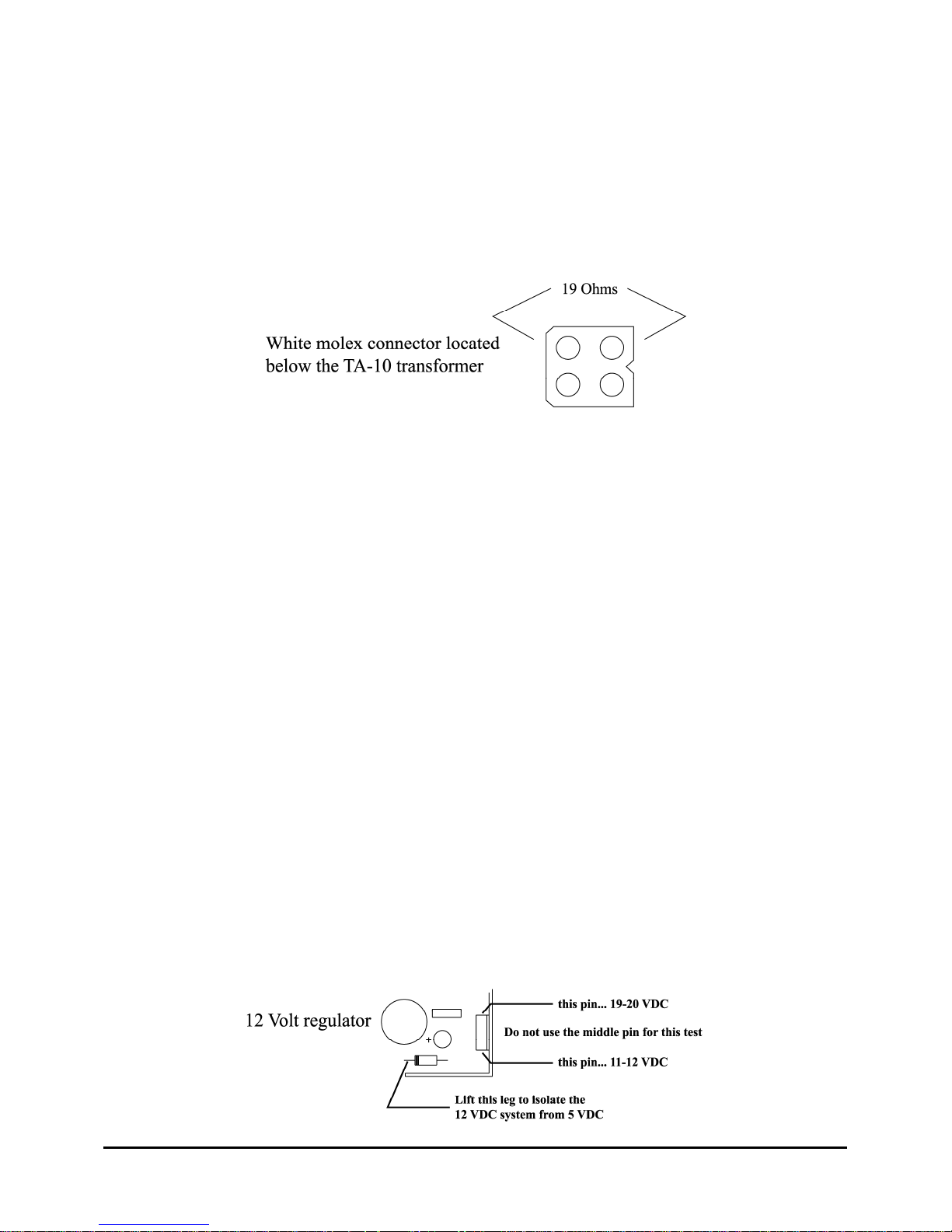
transformer coil as shown here. If the resistance is infinite the transformer is bad. If not, continue.
Next you will need an inline fuse holder with a 1/4 amp slow blow fuse just to be safe. These are
commonly used in car tape decks and can be purchased at any electronics store. Put the leads from the
fuse holder in the white connector as shown on the front page. Turn on the AC to the board.
If the Red LED in the center of the board comes on, the board is probably OK. Use a jumper on the GO
and GND terminals at the top right hand side of the board to operate the automation. Continue.
Plug in the cables one at a time to see which cable causes the shut down.
If the power fuse blows, lift the legs of the diodes as shown in the drawing. Replace the fuse and try
again. If the fuse blows again, the transformer is bad. Replace the transformer.
If the fuse does not blow and the LED does not come on, measure the system voltage on the DC+ and
DC- terminals on the right side of the board as shown on the first page. A healthy board with read 12
VDC. If you read 12 VDC then go to the upper left hand side of the board to the FM-35 terminals.
Measure across the BLK and ORG terminals for 5 VDC.
If you get no voltage at all, lift the diode legs as shown on the first page. Measure as shown for 16 VAC.
If there is not 16 VAC at this point the transformer secondary is defective. Replace the transformer.
If you get a lower voltage and/or a high amount of AC in the DC, one of the power diodes is probably
defective. They must be at least partially removed from the circuit to be tested. Lift one leg of each and
test with the diode check function of a multimeter. Replace as necessary.
If the diodes are fine, check that CAP C2 is mounted properly and not shorted. If C2 is fine, lift the diode
leg as shown below to separate the 12 Volt system from the 5 Volt system. Check the 12 Volt regulator
by reading the pins as compared to the DC- connector on the side of the board.
www.componentengineering.com
31
Page 33

If you have 19 Volts coming in and less than 11 Volts coming out, replace the 12 Volt regulator. If you
have 11-12 Volts coming out, the 12 Volt system is fine.
It is likely that the fault is in the 5 VDC system. Check the diode that you lifted in the last test. Check that
CAP C1 is mounted properly and NOT shorted. If none of these parts are mounted improperly or
defective, replace the 5 Volt regulator.
www.componentengineering.com
32
Page 34
Chapter 13: Troubleshooting the Databus
The first step in trouble shooting a data bus is to check that all the basic wiring has been done correctly.
The next step is to make sure that each device is properly configured for the task it has been assigned.
Take the covers off all of the devices and check that the polarity of the bus wiring is correct throughout
the system. Ensure also that the data bus has not been confused with the DC + and - in the TA-10 or the
AC line and Neutral in the remote boxes.
If you find these errors or hear that these errors were made and
then corrected you will have to replace every 75176 chip in the
system. There is one chip in each device. This is an
inexpensive chip, be sure to replace them all.
While you are at each TA-10 ensure that the address dip
switches are set properly. If two or more switches are set alike
the projectors with the same address will stop at the same time.
While you are at each remote box ensure that
the 1-8 and 9-16 link is set properly to display
the projectors that you have. Further check that
only one individual remote box is designated as
the master. It is best if this remote is at one end
of the Data Bus.
The next step is to determine which two devices are at the ends of the bus. You can tell the ends by the
fact that there is only one pair of wires attached to the device. Once the ends are identified, ensure that the
load screw in each of the end devices is turned full down. No device should have three pairs of wires
attached. If you find this condition or bus wires that are splices together in Tee’s along the way, the bus
will have to be re-wired as a daisy chain with no tees or Ys. Follow the directions in the TA-10 manual
carefully. Electricians have shown little respect for drawings in the past and have strung wire in the
shortest possible path. These wiring mistakes are common and MUST be eliminated.
www.componentengineering.com
33
Page 35
Now turn off all of the devices, TA-10s and Remote
boxes alike. Measure the resistance across the Data +
and -. It should be between 70 and 100 ohms. If the
number is lower than 75 it indicates that some of the
devices in the middle of the bus have their load
screws engaged. You must find these devices and
unscrew the load resistor screw.
If it is higher than normal it indicates that only one-load screws is engaged. If it is very high or infinite
there could be no load screws, a break, or poor connections in the line. Blown 75176 chips can also cause
bad readings.
You must identify the problems and repair them. Once all of these conditions have been met the data bus
is properly setup. If you have done all of these things and are still having problems you need to isolate the
device or wiring that are causing them. Begin at the end of the bus with the master remote on it.
Disconnect the Data + wire and turn on the device. If all is well add another device. What you are trying
to do is create a very small data bus and increase it one device at a time until it fails. Each new device will
have to be loaded as the end device and disconnected from the one in front of it. As they are eliminated as
problems you will need to unload them again before moving on to the next device down the line. When
testing TA-10s without remotes test them by interlocking. It is possible to have 16 TA-10s all running in
interlock at the same time if they are in the same interlock zone.
We have a more advanced troubleshooting tool for problems that are intermittent and occur in a bus that
is properly wired and loaded. This is an RS-232 to RS-485 bus converter and software that enables a PC
running DOS to display the ASCII characters that make up the data on the bus. The adapter plugs into the
75176 socket on any device, TA-10 or remote and into the Com port of your PC. You will be able to see
all of the functions that are displayed on a remote in a graphical display. Below the display is a running
data stream. Unused or distorted characters will be displayed if Zenon strikes are getting in or
undiscovered tees or Ys exist on the data bus. Please call to request these advanced tools and for help
using them.
www.componentengineering.com
34
Page 36
Appendix A: Cue Assignment Sheet
www.componentengineering.com
35
 Loading...