

Page 1
Compology
Tech App & Maintenance
Page 2

The Basics
NOTICE:
This device complies with Part 15 of the FCC Rules and with Industry Canada licence-exempt RSS standard(s).
Operation is subject to the following two conditions:
1. this device may not cause harmful interference, and
2. this device must accept any interference received, including interference that may cause undesired operation.
Le présent appareil est conforme aux CNR d'Industrie Canada applicables aux appareils radio
exempts de licence. L'exploitation est autorisée aux deux conditions suivantes:
(1) l'appareil ne doit pas produire de brouillage, et
(2) l'appareil doit accepter tout brouillage radioélectrique subi, même si le brouillage est susceptible d'en compromettre le
fonctionnement.
NOTICE:
Changes or modifications made to this equipment not expressly approved by Compology may void the FCC authorization to
operate this equipment.
Page 3

Compology Conduct
As a Compology Technician, it is important to be a positive representative of Compology and the companies
we work with. The following are rules you must follow when performing any work on behalf of Compology
Attire, grooming
● Look professional (no torn, stained clothing)
● Wear your Compology logo’d apparel if appropriate
Identification
● Carry personal identification
● Carry Compology identification/Business cards (if provided)
● Wear your Compology high vis vest and hard hat
Behavior
● Do
○ Be polite & friendly
○ Smile!
○ Practice safety!
● Dont
○ Foul language
○ Pressure customer/insist to do install
○ Avoid interaction with customers
○ Use customer facilities
Page 4

On-site Behavior
Customer objections
● Never argue with customers
● If an individual has an objection to your being there or having a camera installed, give them contact
information for the project point of contact and leave the site
○ Maintain a polite & positive attitude
○ Contact Compology and let them know you were unable to complete the install, the circumstances
and whom you dealt with on location
Unable to install & reporting
● Immediately notify Compology & Customer if a business/individual shows objections to having a camera
installed on their container.
Site tidiness and clean up
● Leave No Trace policy: Pick up any debris created during installs (empty boxes, drill bits, etc).
● No loitering on site, leave promptly
Zero tolerance items
● Theft
● Smoking
● Alcohol or drug use
Page 5

On-site Behavior (continued)
Complaints
As a Technician, you will visit businesses and residences to service Compology equipment and there can be
times when you receive a complaints from them
● A complaint is any scenario of the following scenarios:
○ Does not want sensor installed/did not approve installation
○ Was not notified by Hauler
○ Starts asking questions about issues with their service with the Hauler
Responses
● If a complaint is related to sensor installation, offer to come back another time after they have spoken
with the Hauler. Provide letter of authorization and contact information
● If a complaint is related to hauler service, provide contact information for Hauler representative and verify
that they are comfortable with installation.
Reporting
● Report all complaints to the Compology project manager same day.
○ Information needed when giving report:
■ Business/Location Name
■ Address
■ Date & Time
■ Name of individual making complaint
■ Any other useful information
○ Compology main number: 415-848-9169
Page 6

Compensation
Installations
$20 flat rate per install
Maintenance
$40 flat rate per task
$30 flat rate per
attempted task
Page 7
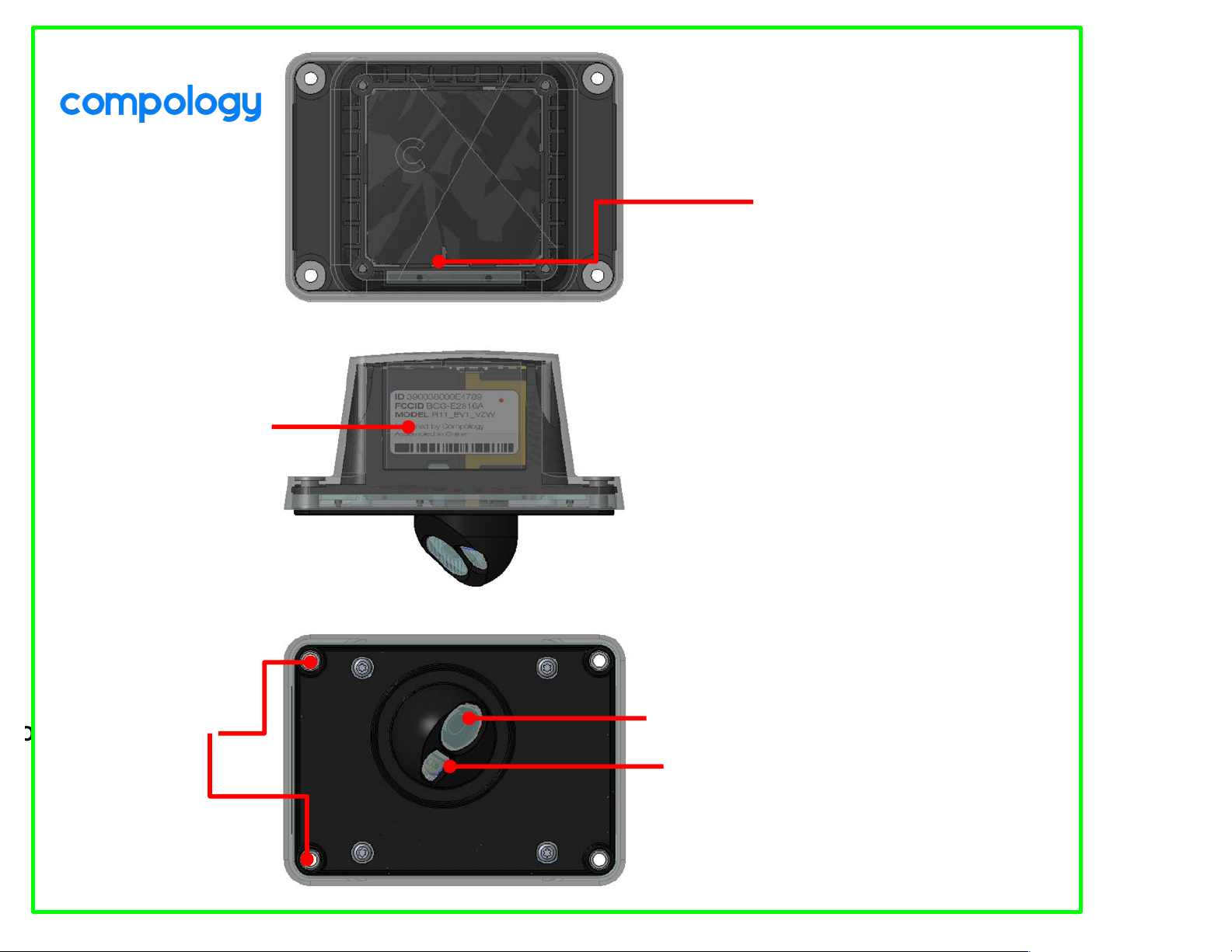
CAMERA
FLASH
STATUS INDICATOR LIGHT
● Turning On
● Turning Off
● Sensor Good
ID LABEL
Page 8
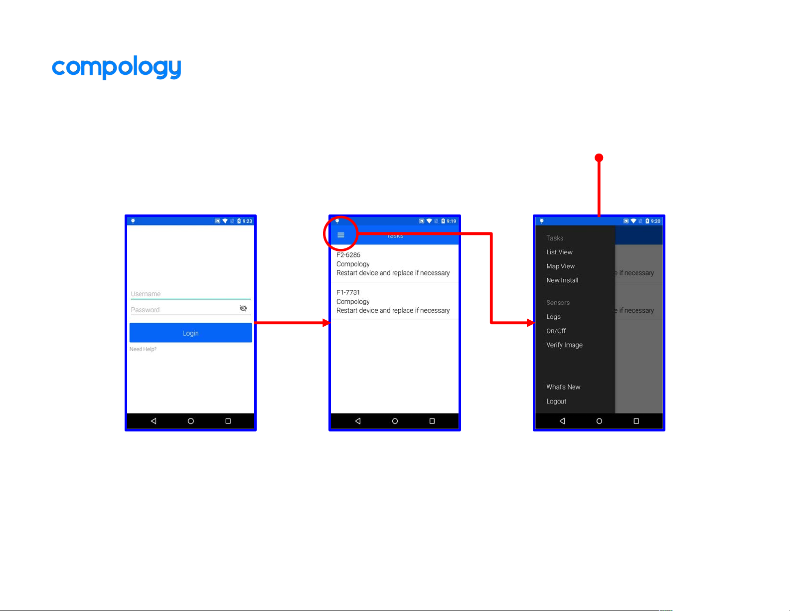
Main Menu
1. Login 2. Click Icon 3. Main Menu
Page 9
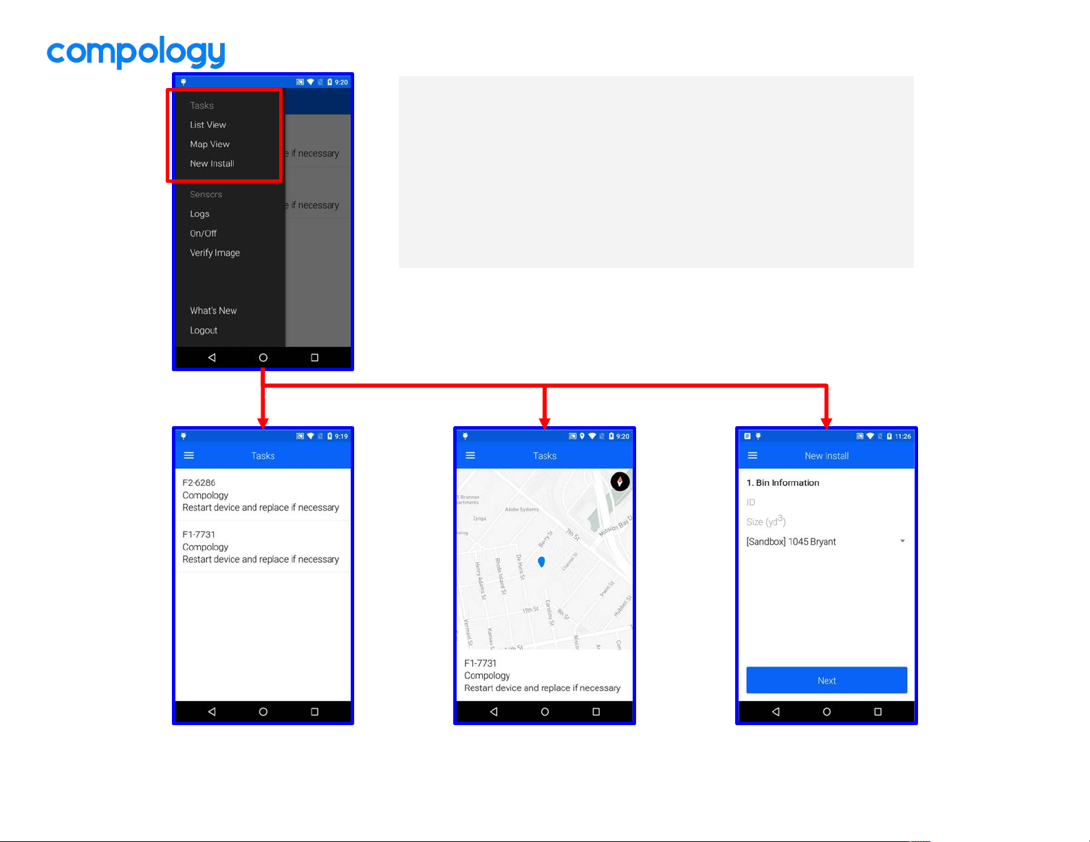
Tasks
Start here to complete maintenance tasks or installs
● List View – View of maintenance tasks in a list
● Map View – View of maintenance tasks on a map
● New Install – Create a new bin and assign a sensor
Map ViewList View New Install
Page 10
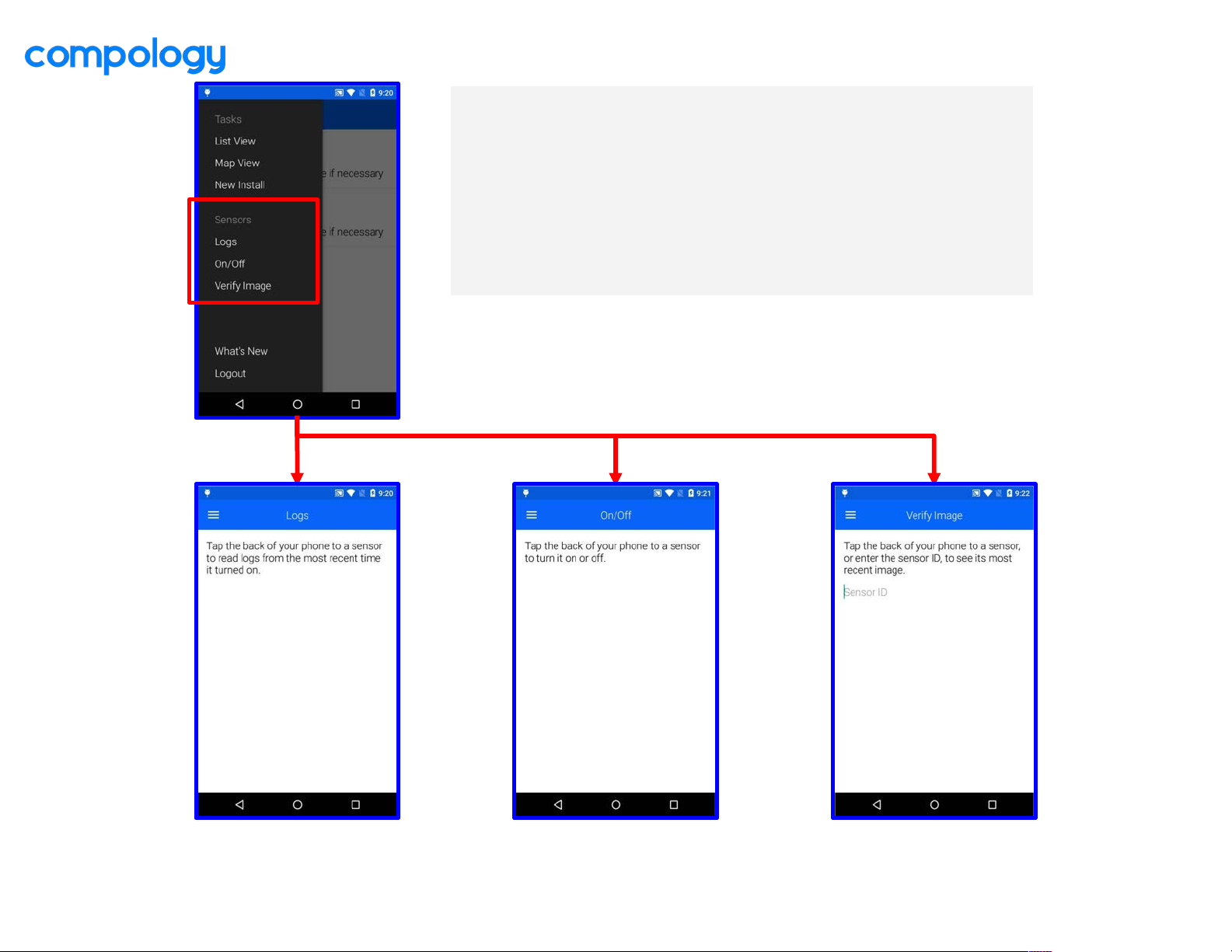
Sensor Tools
Tap phone to sensor to interact and get info
● Logs – View diagnostic info on a sensor
● On/Off – Turn sensor on or off
● Verify Image – See the latest image from a sensor
On/OffLogs Verify Image
Page 11

New Install
Page 12
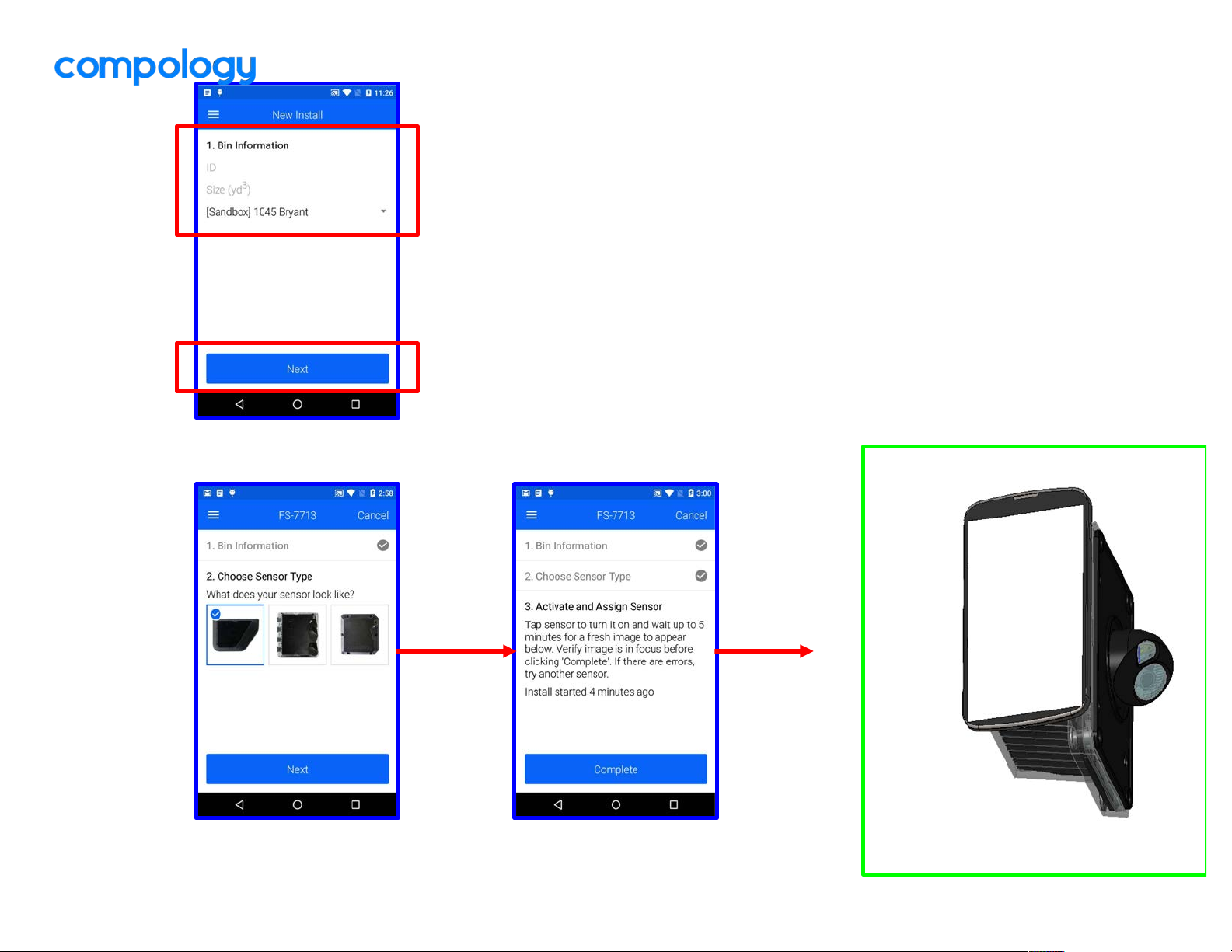
3. TAP PHONE TO
SENSOR TO ACTIVATE
2. CHOOSE SENSOR
TYPE
1. ENTER BIN INFORMATION
● ID – Enter number/name on outside of bin
● Size – Enter the size of bin in cubic yards
● Organization – Select the organization for this bin
● Content – Select the type of material in container
IMPORTANT: You will need to select an
organization if you are assigned to multiple.
Make sure you select the correct one!
CLICK & HOLD
Position flat
over
sensor’s
label
surface as
shown
Page 13
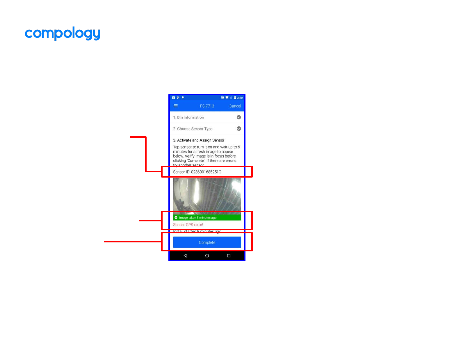
If you see ‘Sensor GPS Error’:
1. Move to a location where you
can see the sky,
2. Restart current sensor and wait
for new image
3. If GPS error remains, try new
sensor
IMPORTANT: Do not install sensor
with GPS error.
If new image does not appear
within 15 minutes:
1. Restart the current sensor by
tapping sensor to turn off and
then on
2. Wait for new image
3. If no new image appears, try
new sensor
IMPORTANT: Do not install sensor if
new image does not appear
ID of the sensor waiting to
be assigned to the bin.
Tapping any sensor will
turn on or off that sensor
and change the ID
4. VERIFY GREEN IMAGE
& NO ERRORS
5. COMPLETE
Page 14

Turning Sensor On/Off
Page 15
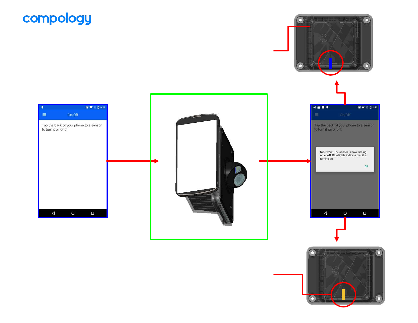
TURNING OFF
Immediately, yellow light will
blink 10X very quickly and
then turn off
TURNING ON
Wait 5-10s, blue light will
blink slowly 5X, and then
flash a blue light every 2s
during startup sequence
IMPORTANT: Make sure any
sensors in your bag or inventory are
OFF and all sensors you are installing
into bins are ON. Pay careful
attention to the indicator lights.
Position flat
over
sensor’s
angled
camera
surface as
shown
“DING!”
On/Off will be used to turn a sensor
on or off when not in a task. You can
use it to restart a sensor you want to
check.
Position flat
over
sensor’s
label
surface as
shown
Page 16

Checking Sensor Logs
Page 17
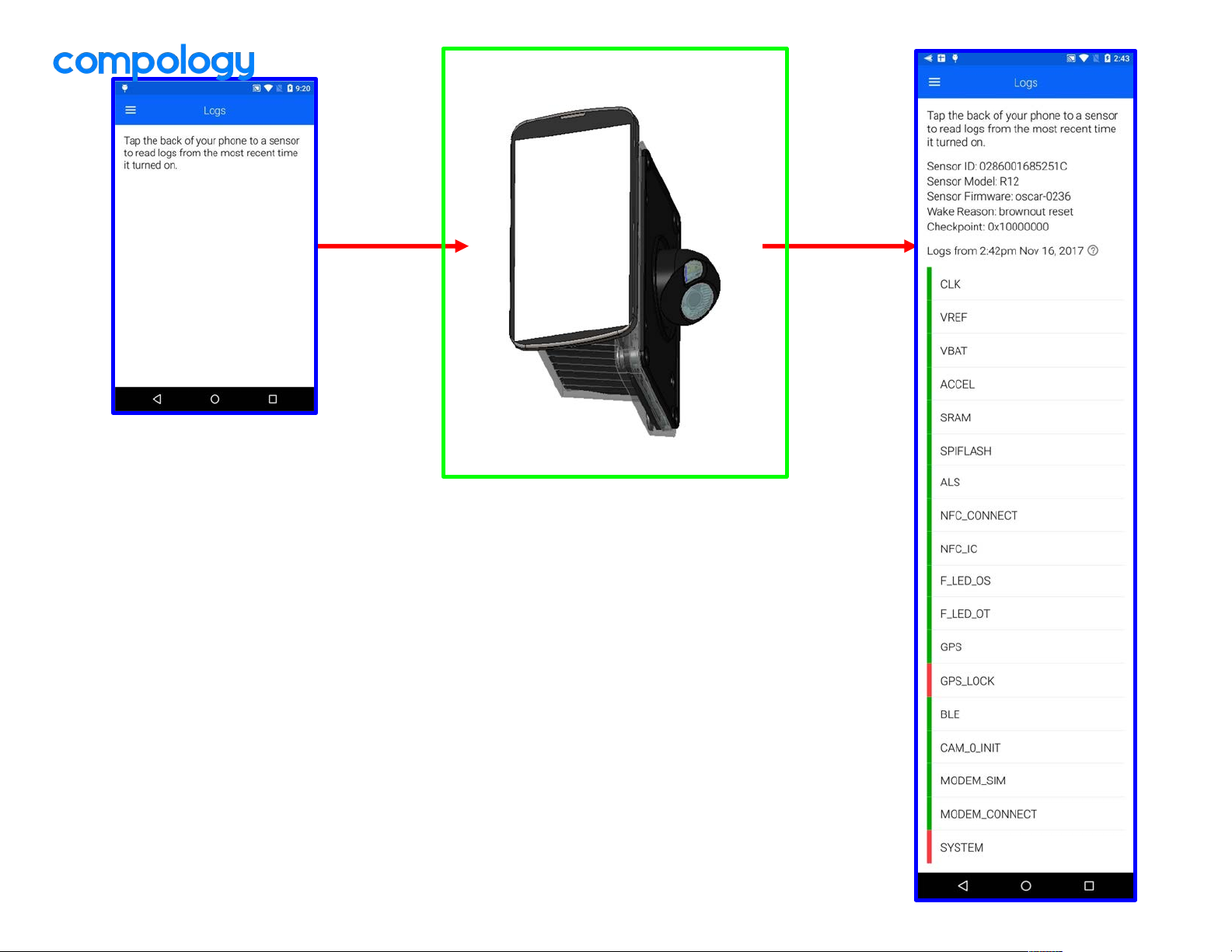
Position flat
over
sensor’s
angled
camera
surface as
shown
“DING!”
Most common errors:
● MODEM_CONNECT (cannot
get cell signal). In this situation,
restart sensor and try again
before replacing
● GPS_LOCK (cannot get GPS
signal). Move to a location
where you can see the sky and
try again before replacing
sensor
● SYSTEM will be an error if
anything has failed
Green = Good
Red = Error
Logs should be used to
identify root issues when a
sensor is not uploading an
image. It can only be taken
after a sensor has gone
through it’s startup sequence
and the indicator light is no
longer flashing.
Position flat
over
sensor’s
label
surface as
shown
Page 18

Verify Image
Page 19
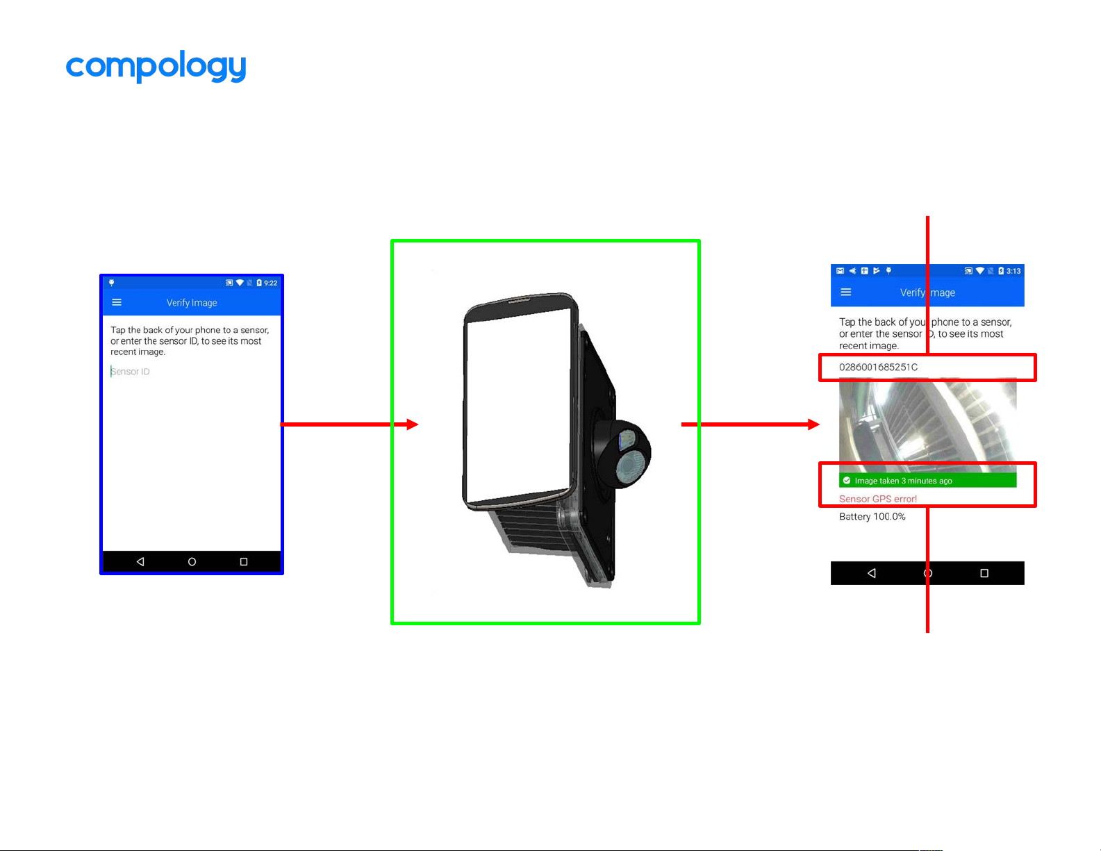
“DING!”
SENSOR ID
VERIFY GREEN IMAGE &
NO ERRORS
Verify Image should be used after a
sensor is restarted to check to see if
an image was uploaded successfully
Position flat
over
sensor’s
label
surface as
shown
Page 20

Maintenance
Page 21
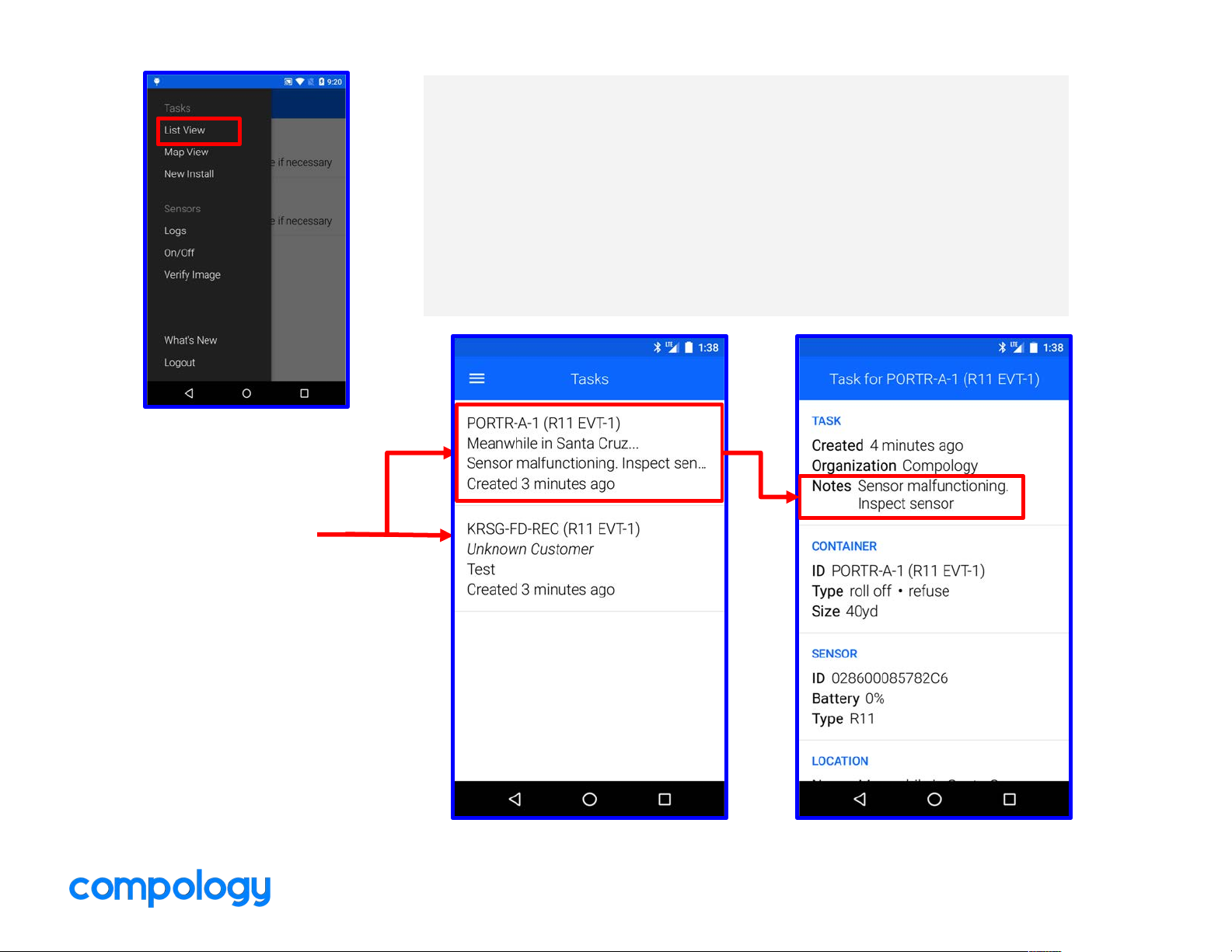
Viewing Tasks
Start here to complete maintenance tasks
● List View – When a task is assigned to you, it will appear on
this list. Tasks will stay here until it is completed, skipped or
removed by a Compology Manager
● Task Notes – Each task will have instructions for you to
follow
Task DetailsList View
Each individual
task to complete
is listed here
Page 22
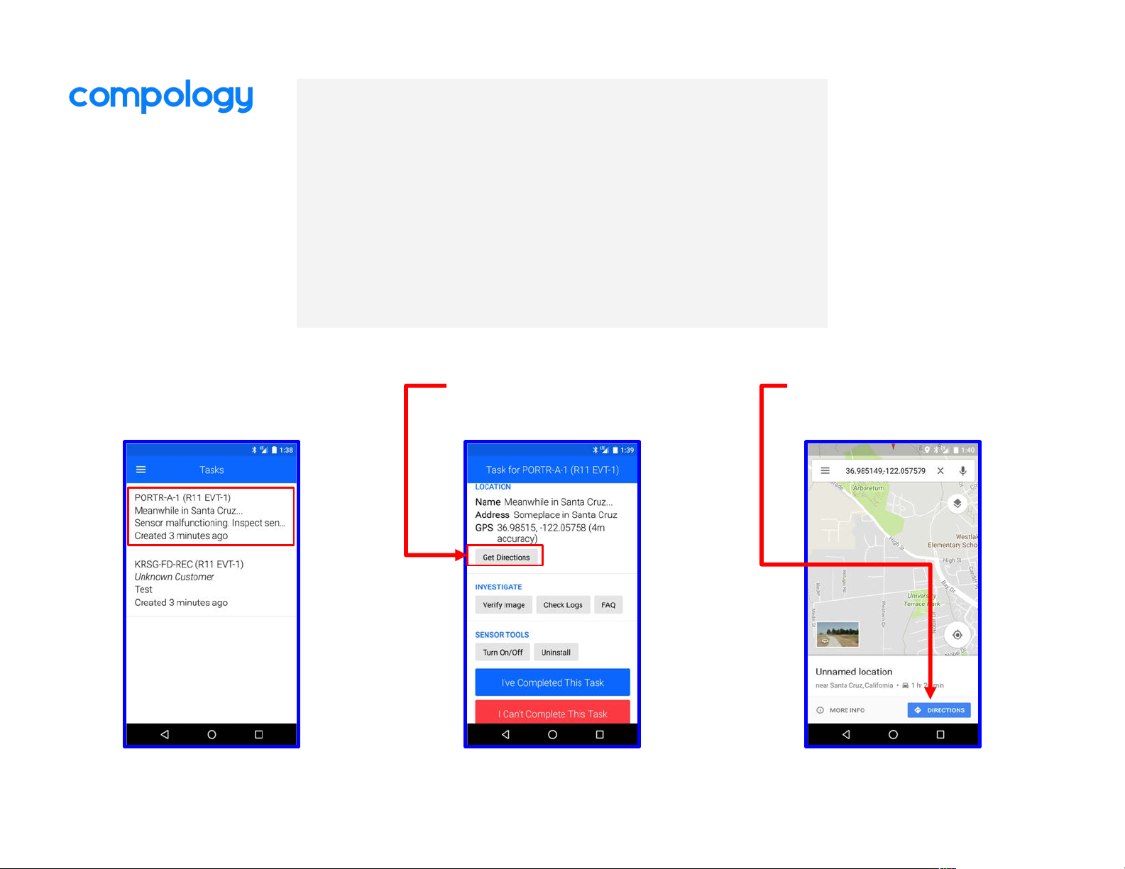
Finding the Sensor
Find the last known location of the sensor
1. Select task you want to complete from the List
View
2. Scroll down and select “Get Directions”. Google
Maps will automatically appear
3. Select “Directions”
3. Google Maps1. Select Task
2. Get Directions
Page 23
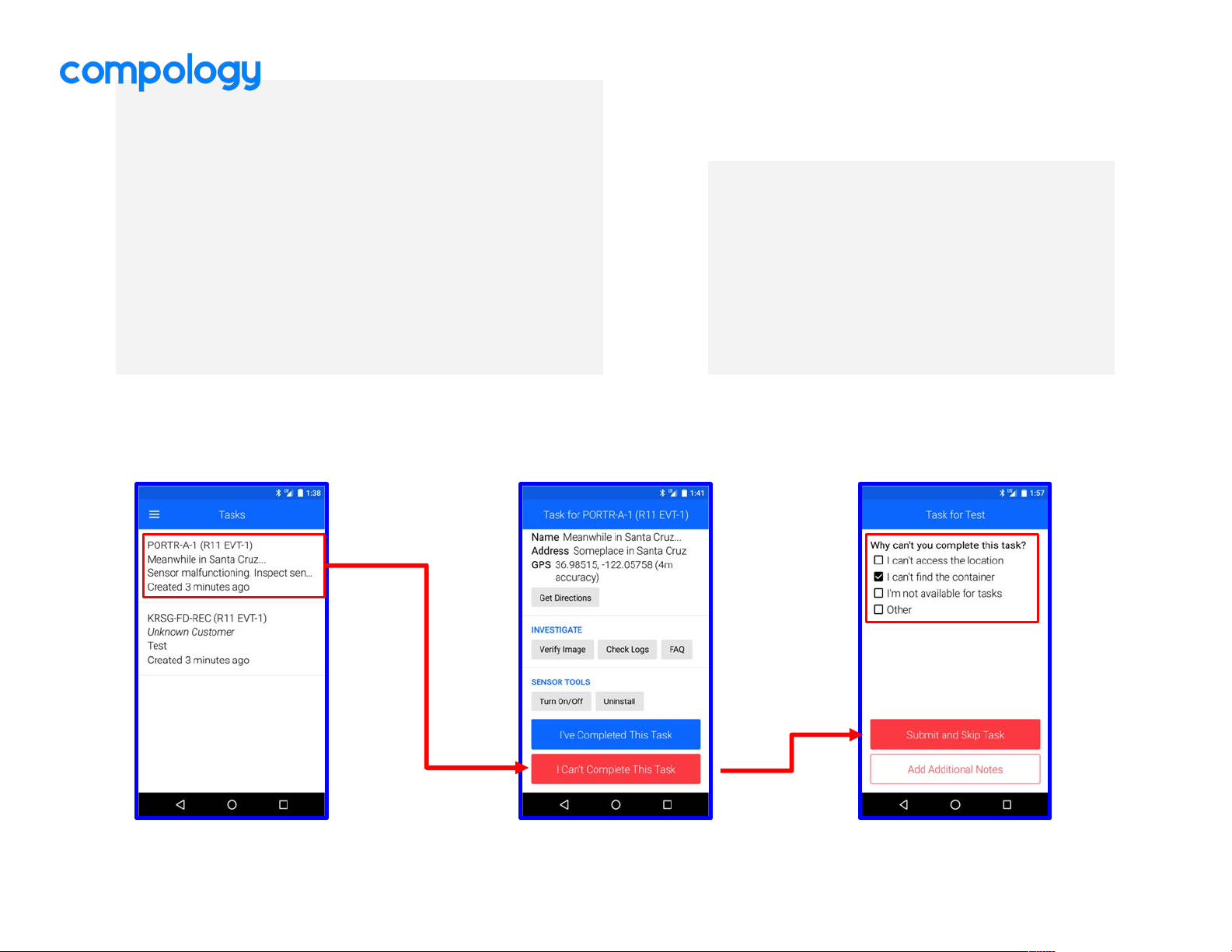
Can’t find the Container
If you arrive to the location provided by Google Maps
and the container is not there, or you cannot access
the location:
1. Select the task for that specific sensor
2. Scroll down to the bottom of the task
3. Select “I Can’t Complete This Task”
4. Mark all boxes that apply
5. Select “Submit and Skip Task”
Select options,
Skip Task
1. Select Task 2. Scroll down
You’ve located the
container?
CONTINUE TO NEXT PAGE
Page 24
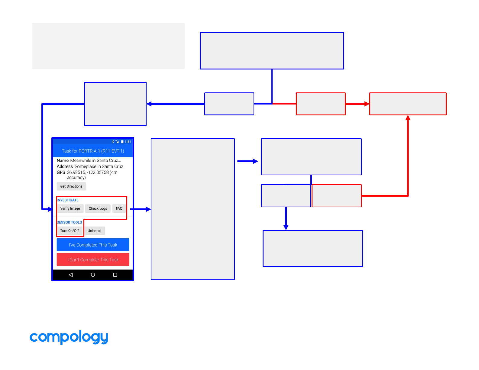
Troubleshooting the
sensor
Is the sensor missing or physically
damaged?
YES
Replace sensor.
Go to next page
NO
Use task
tools to
investigate
issue
To investigate-
1. Turn sensor
off & on again
1. Check for
green logs
1. Check for
new image
Did the sensor post
green and get a new
clear image?
YES NO
Select “I’ve Completed
This Task”
Page 25
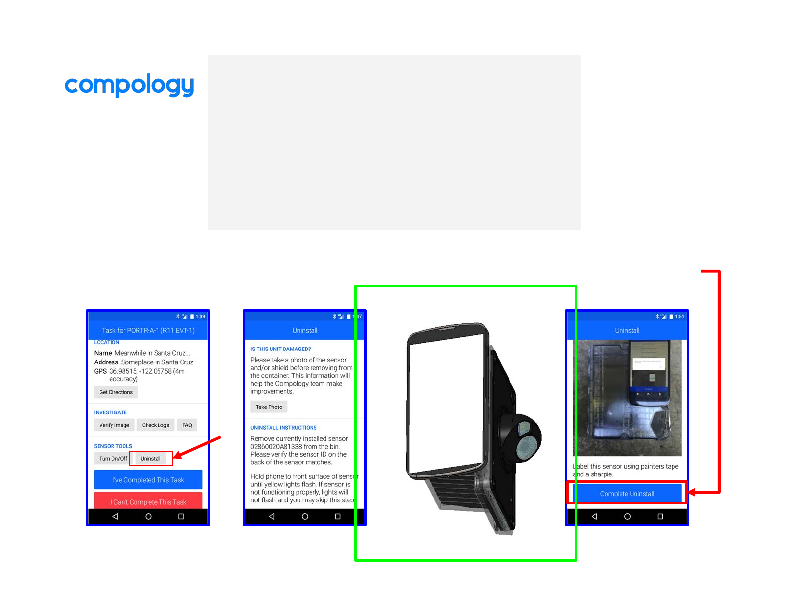
Replacing a sensor
Procedure to replace a sensor
1. In the task, select “uninstall”
2. Turn off sensor
3. Complete Uninstall - Continue to next page
3. Complete
Uninstall
1. Select “Uninstall”
2. Uninstall
instructions
Position flat
over
sensor’s
angled
camera
surface as
shown
Position flat
over
sensor’s
label
surface as
shown
Page 26
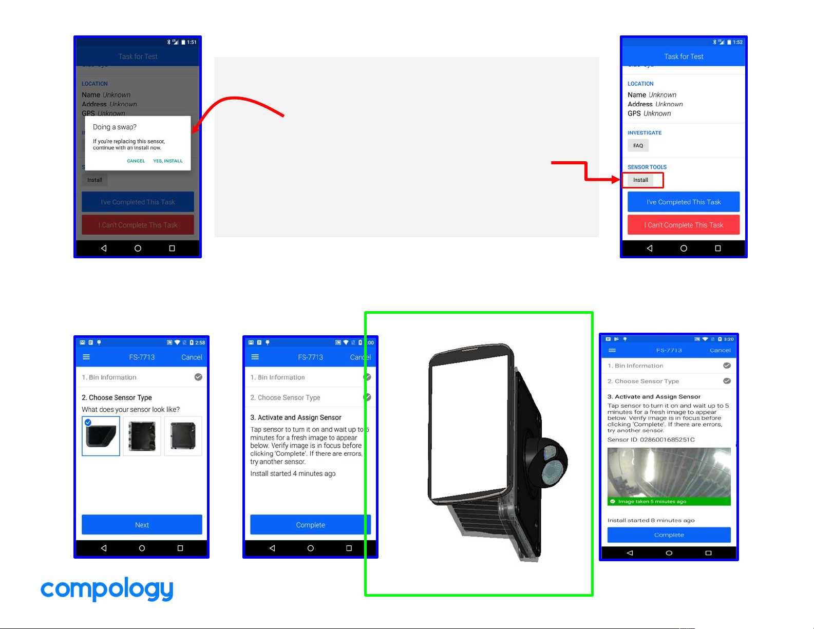
Replacing a Sensor (continued)
Procedure to replace a sensor
Click “Yes, Install” button on swap window
*If window does not appear, click “install” in task*
1. Select new sensor type
2. Turn on new sensor
3. If sensor flashes green light, select “complete”
1. Select Sensor
Type
2. Activate sensor
Position flat
over
sensor’s
angled
camera
surface as
shown
3. After green light,
select “Complete”
Position flat
over
sensor’s
label
surface as
shown
Page 27
After Completing a Task
RETURNING SENSORS
● All damaged or malfunctioning sensors must be marked with tape and shipped back to
Compology HQ
Address:
○ 1045 Bryant Street, Suite 101, San Francisco, CA 94103
○ Fedex Account to charge will be provided by Compology
Page 28
Physical Install
& Uninstall Overview
Page 29

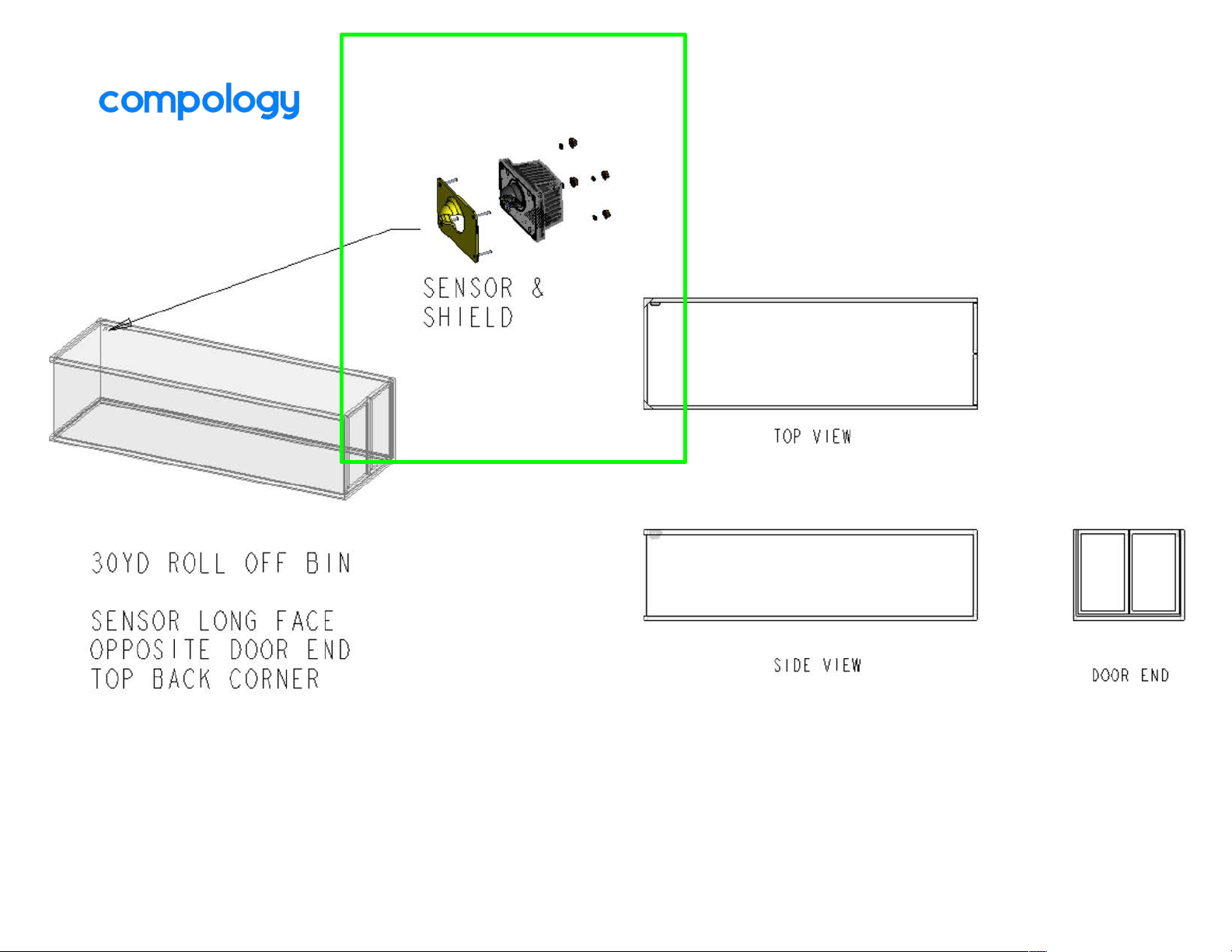
R13 Roll Off
Install Instructions
Page 30
Page 31
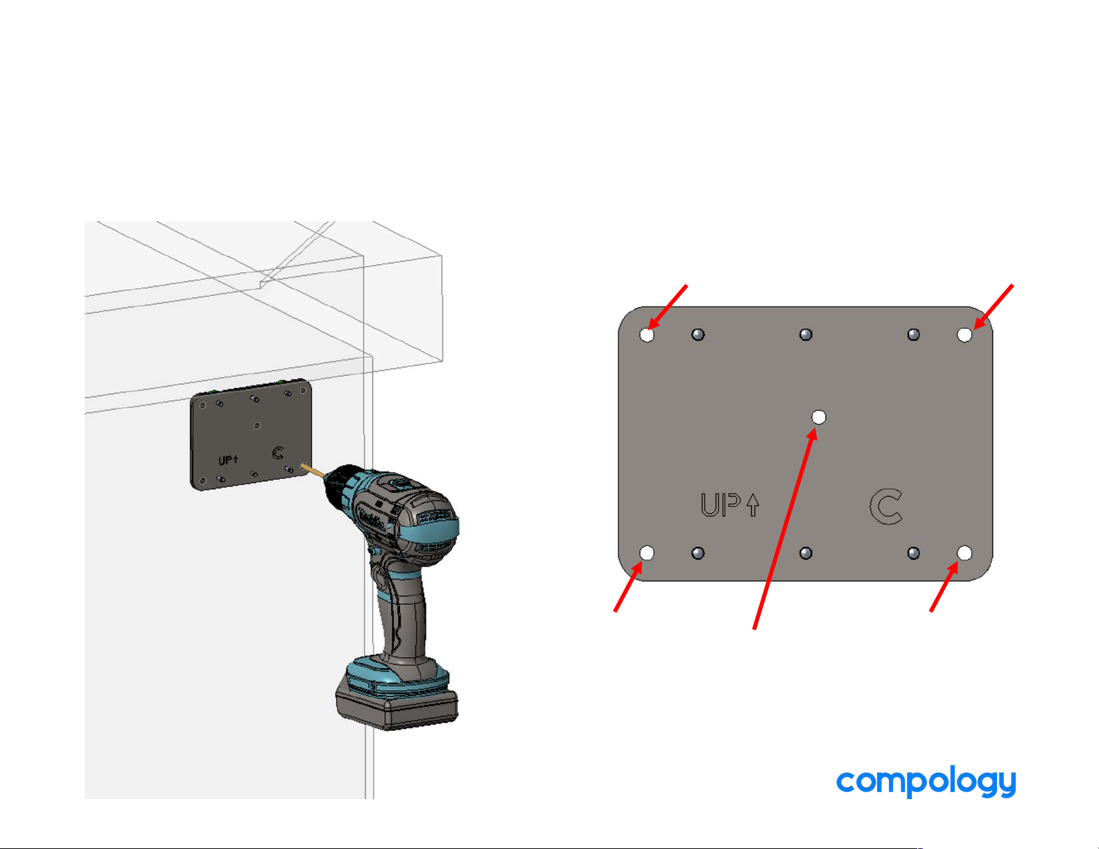
1. COMPLETE ‘NEW INSTALL’ WITH COMPOLOGY TECHNICIAN APP
2. POSITION TEMPLATE BELOW BIN’S TOP BOX BEAM
3. DRILL FIVE 3/16” HOLES (ALL CORNERS PLUS TURRET CENTER)
See ‘Mounting Locations’ document for positioning
1 2
3 4
5
Page 32
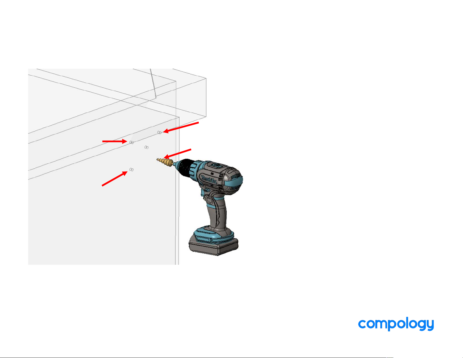
4. OPEN UP CORNER HOLES USING STEP BIT
Page 33
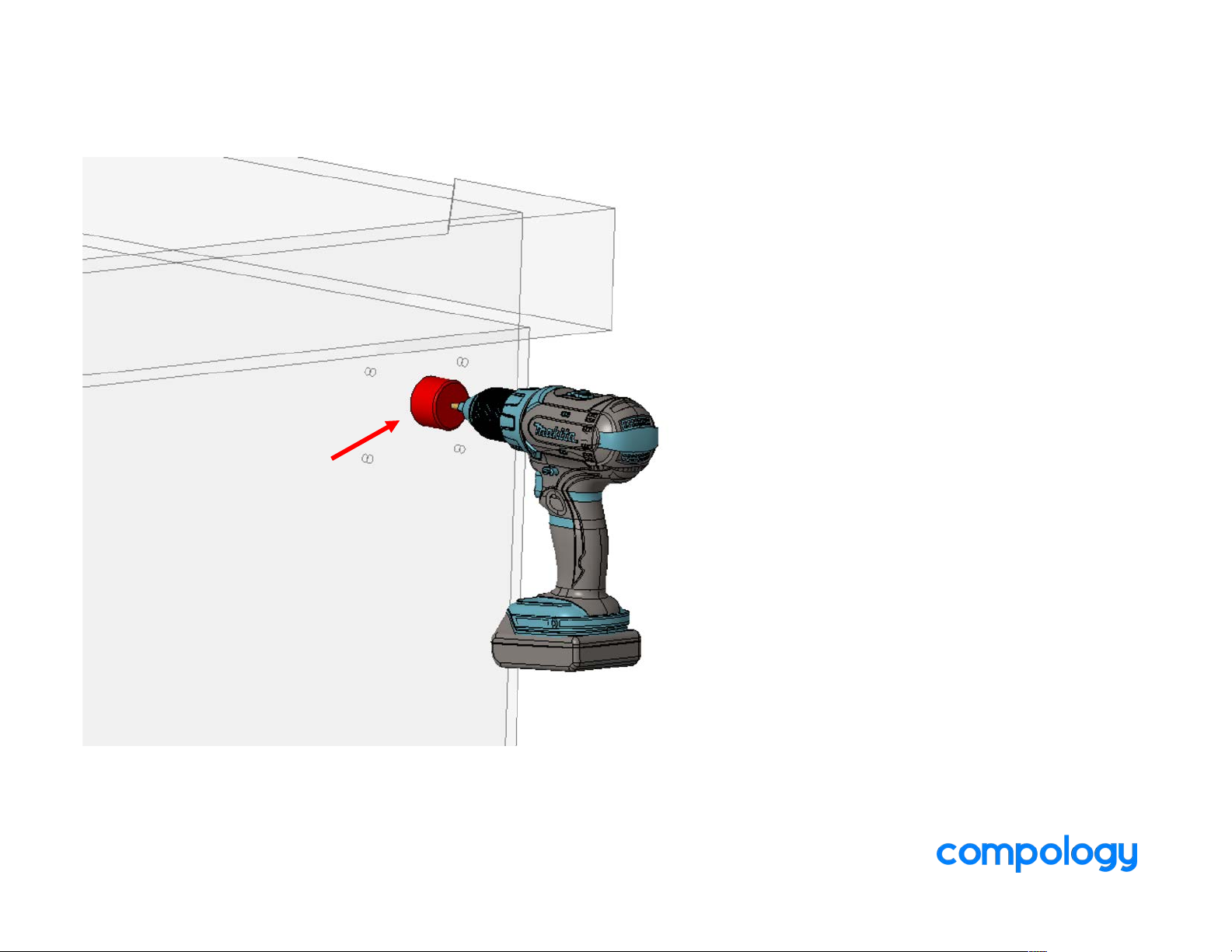
5. DRILL OUT CENTER HOLE WITH HOLE SAW
Page 34
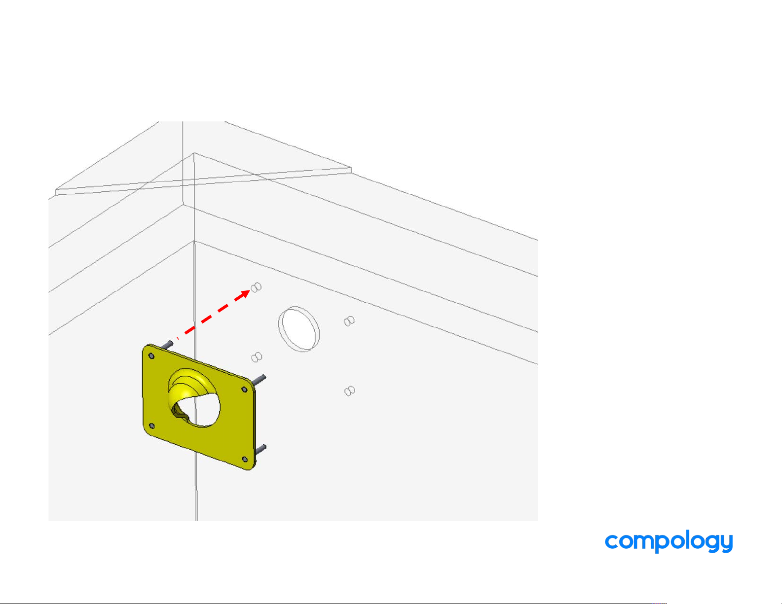
6. REMOVE TAPE LINERS AND PLACE SHIELD ON INSIDE
OF BIN. STUDS SHOULD ALL PENETRATE HOLES
Page 35
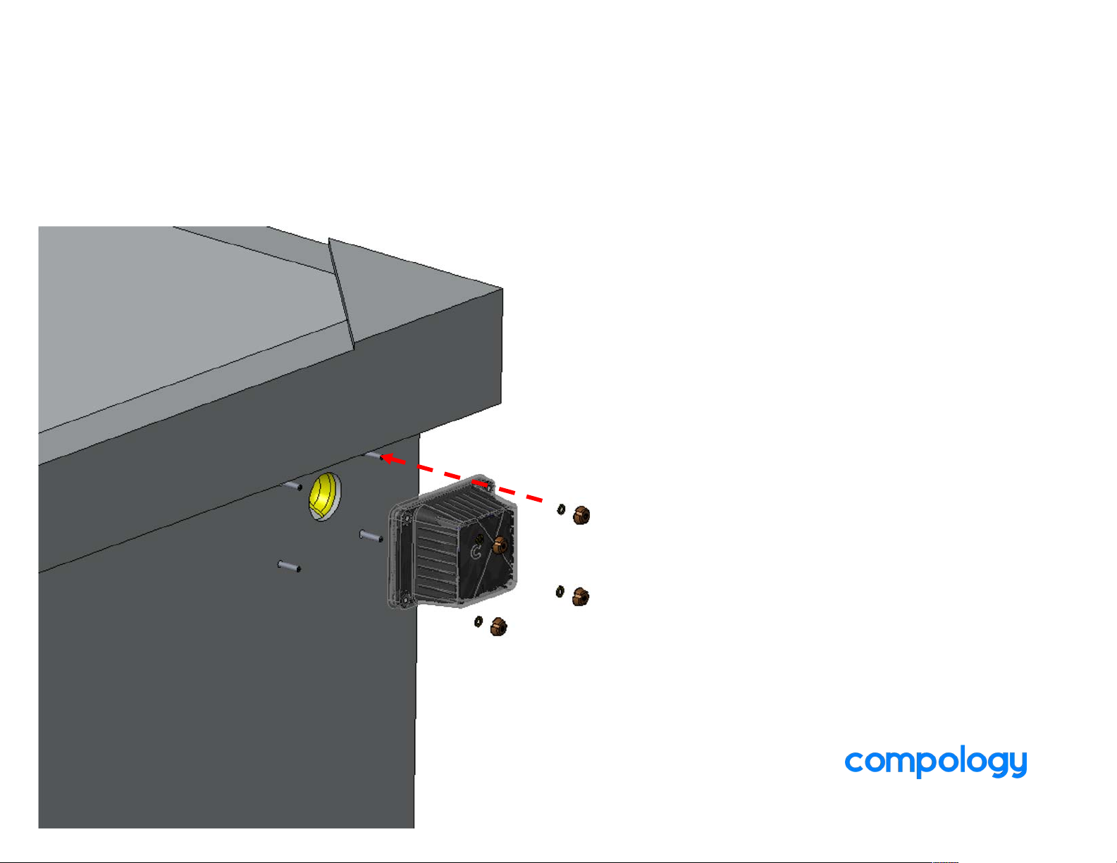
7. PLACE CAMERA ON STUDS (OUTSIDE OF BIN)
8. SECURE USING LOCK WASHERS AND SECURITY NUTS
Page 36
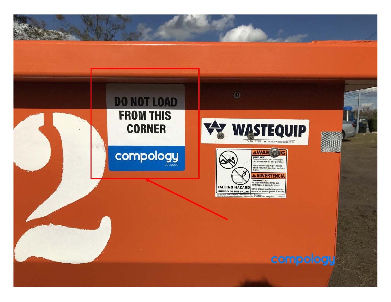
Sticker
Page 37

R13L Trailer
Install Instructions
Page 38
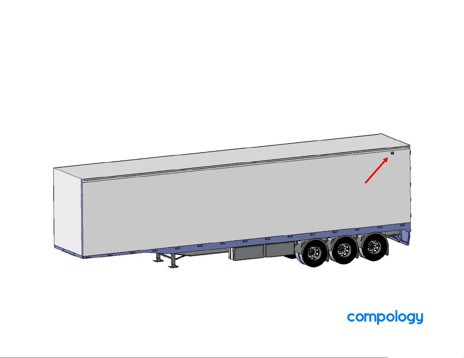
MOUNTING LOCATION:
DOOR END, AS HIGH AS POSSIBLE.
- AVOID DOOR IMPACT
- AVOID STIFFENERS
- BELOW ROLL-UP DOOR TRACK (IF APPLICABLE)
- AVOID RIVETS AND OTHER PROTRUSIONS
Page 39
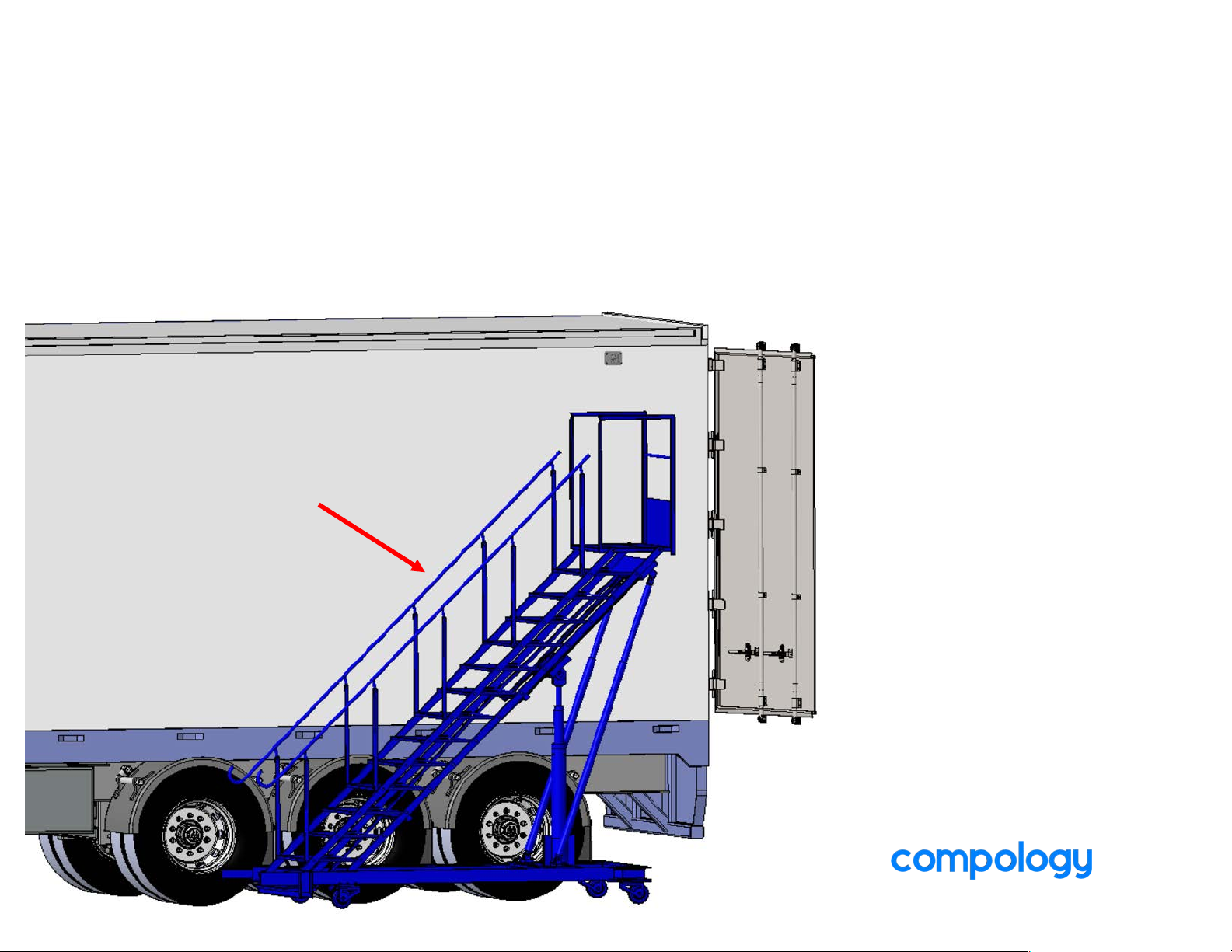
LADDER SAFETY IS VERY IMPORTANT!
- USE A PLATFORM LADDER, IF POSSIBLE
- NEVER USE AN EXTENSION LADDER
PLATFORM
LADDER
Page 40
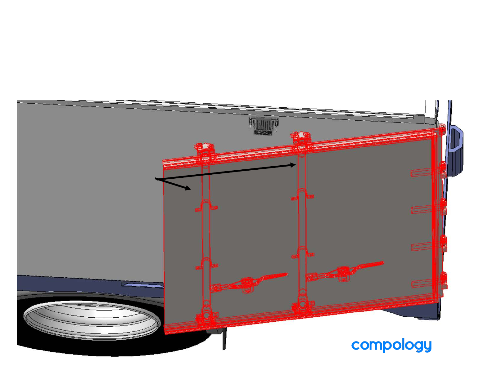
MAKE SURE TO PLACE IT FAR ENOUGH FORWARD TO AVOID
DOOR PINCH.
THIS TYPICALLY MEANS IN FRONT OF THE FIRST LOCKING
BAR.
LOCKING BARS
PINCH AREA
Page 41
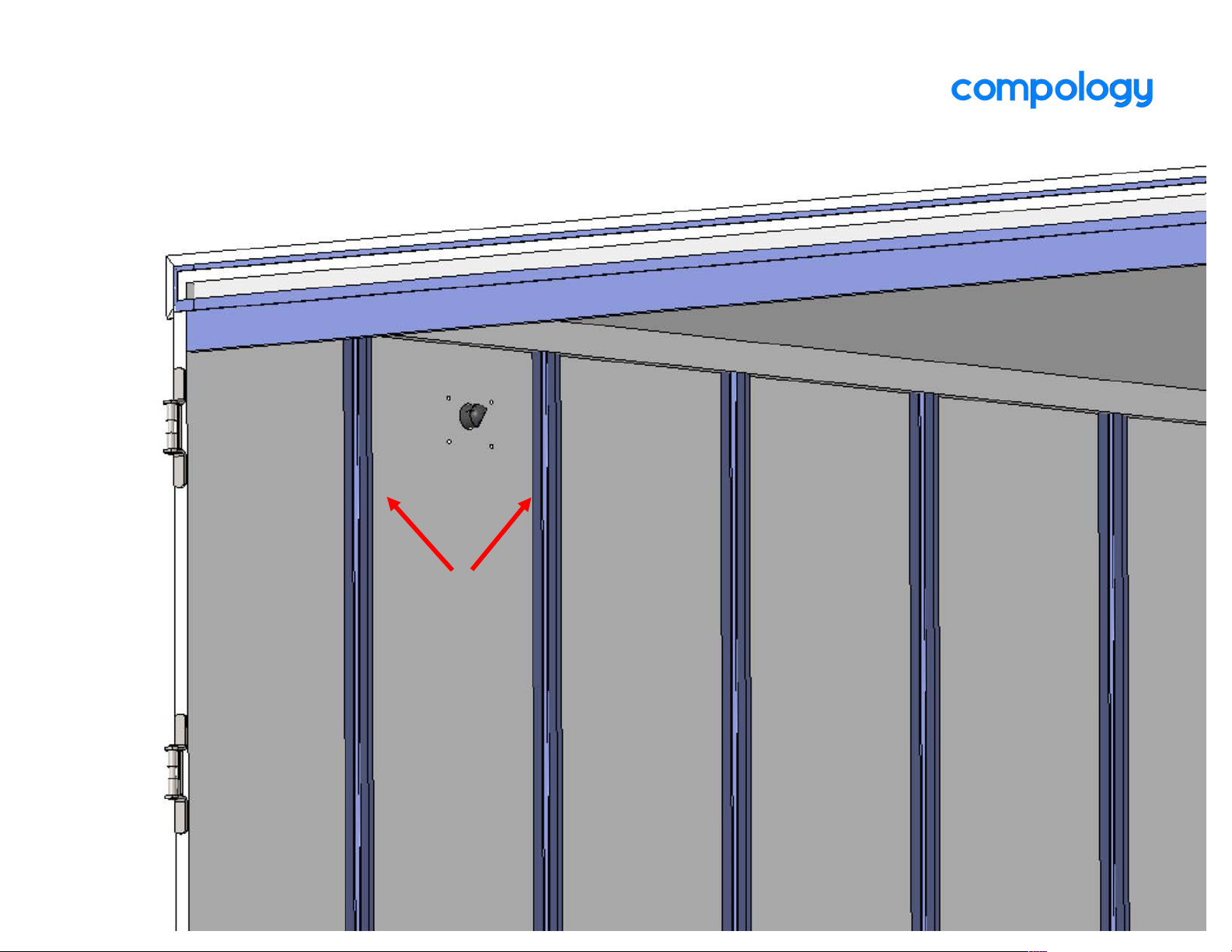
MAKE SURE TO AVOID STUDS / STIFFENERS.
STUDS
Page 42
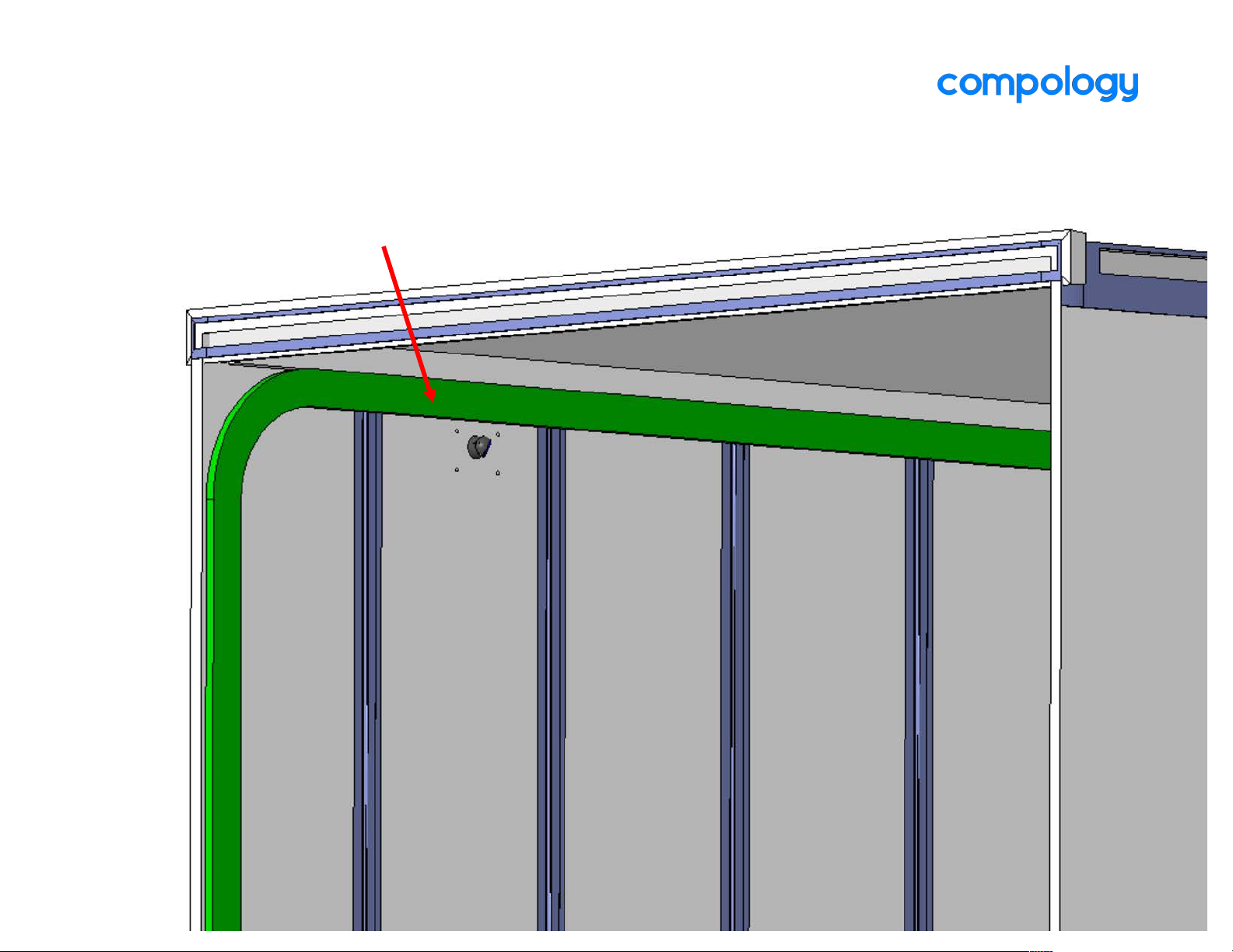
IF THE TRAILER HAS A ROLL-UP DOOR, PLACE THE SENSOR
BELOW THE TRACK.
DOOR TRACK
Page 43
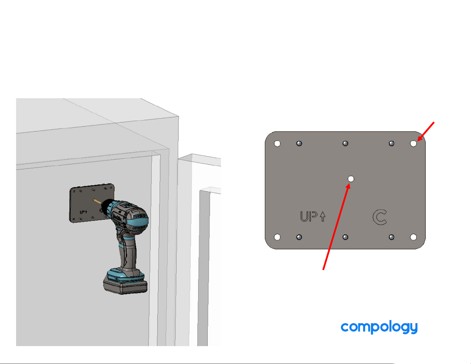
1. COMPLETE ‘NEW INSTALL’ WITH COMPOLOGY TECHNICIAN APP
2. PLACE TEMPLATE ONTO TRAILER WALL
3. DRILL CENTER HOLE AND ONE CORNER USING 3/16” DRILL BIT
2
1
Page 44
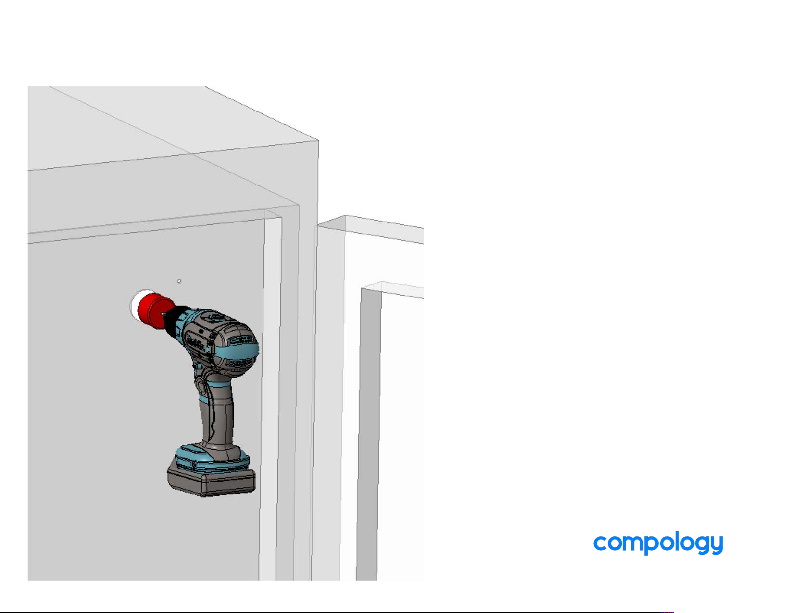
5. DRILL OUT CENTER HOLE WITH HOLE SAW
Page 45
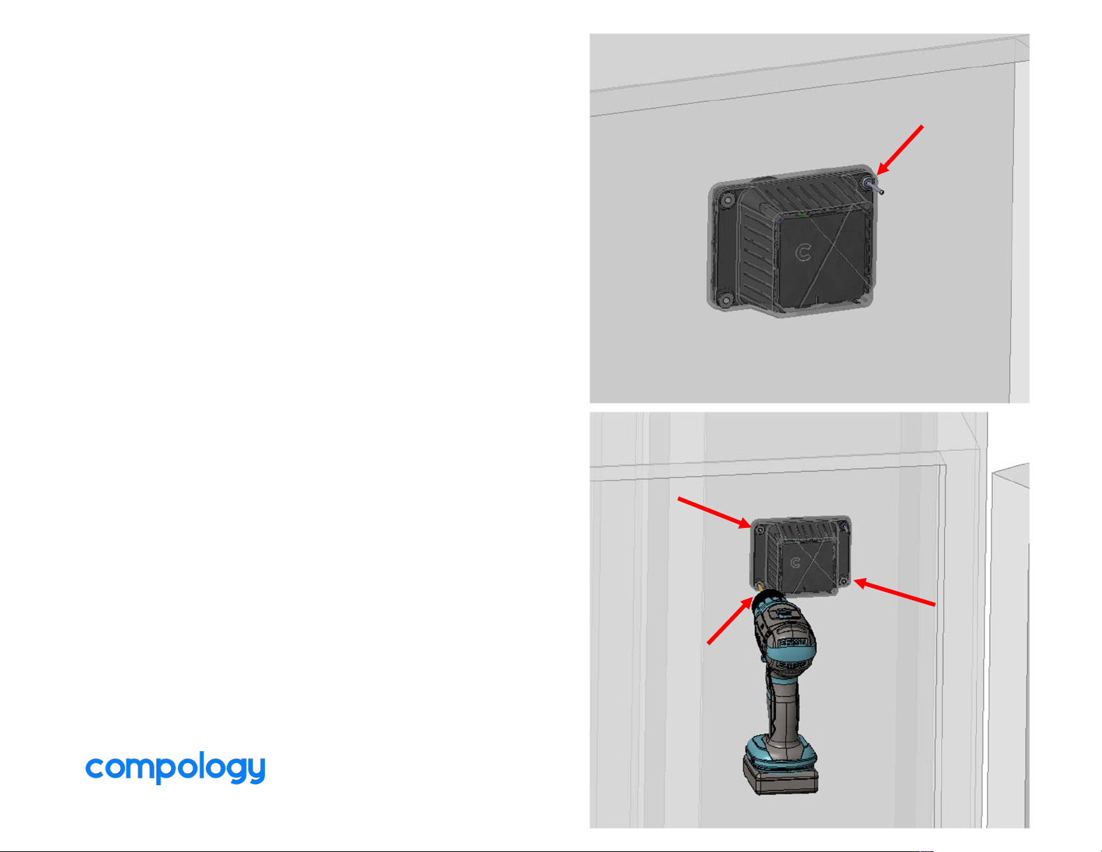
5. PLACE R13L INTO LOCATION AND RIVET ONE
CORNER.
6. MATCH-DRILL AND RIVET OTHER CORNERS
Set one
rivet first
2
3
4
Page 46

General Information
Compology Contacts
Blake Miller
Dana Beck
Steve Kent
Operations
Compology HQ
1045 Bryant Street, Suite 101
San Francisco, CA 94103
415-848-9169
 Loading...