

Page 1

HTT-1
Function Tester
Instruction Manual
COMPLIANCE WEST
USA
Page 2

i
Page 3

Dear Customer:
Congratulations! Compliance West USA is proud to present you
with your HTT-1. The operating instructions are included in the
Manual, so please retain this information for future use.
Thank you for your trust and confidence.
Rev. 2.0, February 2009
ii
Page 4

ii
Page 5

Table of Contents
Operating Instructions ................................................................................................................................1
Theory of Operation .....................................................................................................................1
Introduction and Specifications ..................................................................................................................2
Introduction ..................................................................................................................................2
Specifications ...............................................................................................................................2
Operation ....................................................................................................................................................3
Setting up the HTT-1....................................................................................................................3
Front Panel Features.....................................................................................................................3
Setup Procedure: Hipot Tester ....................................................................................................3
Setup Procedure: Ground Continuity Tester ...............................................................................4
Unanticipated Results...................................................................................................................4
Troubleshooting the HTT-1........................................................................................................................7
Technical Assistance ..................................................................................................................................8
iii
Page 6

Section 1
Operating Instructions
Theory of Operation
withstand and continuity testers, including high current models delivering up to 30 amps. It
allows function tests of all three failure modes to ensure that your tester is functioning properly.
The HTT-1 is not designed to verify calibration points except as noted in the
Specifications Section of this manual. Optional calibration point verification is available as an
option. Contact the factory for details.
The HTT-1, used daily, will prove function of the safety testers before shifts or before
testing of a lot of products. It is provided with three switches which simulate passing and failing
equipment for ground continuity, high leakage between primary circuits and ground, and
dielectric withstand failure between primary and ground circuits. While all three switches can be
simultaneously set for failing modes, we recommend that the HTT-1 be set with one failure at a
time to ensure that your testers are functioning correctly.
A proper test plan would be constituted of the following tests:
showing proper connection of the HTT-1 to any dielectric tester and any high current ground
continuity tester you may wish to test.
tester. It is recommended that it be removed from service until the problem can be resolved.
Section 4 of this manual also has troubleshooting information to help you determine if the HTT-1
is functioning correctly.
The HTT-1 is designed to be a solution for fast, easy function testing of all dielectric
1. Connect HTT-1 to the tester outputs.
2. Set all three switches on the HTT-1 to ‘PASS’.
3. Verify passing result on the Tester.
4. Set the Ground switch on the HTT-1 to ‘FAIL’; set both other switches to
‘PASS’.
5. Verify Ground failure on the Tester.
6. Set the Leakage switch on the HTT-1 to ‘FAIL’; set both other switches to
‘PASS’.
7. Verify Leakage current failure on the Tester.
8. Set the Hipot switch on the HTT-1 to ‘FAIL’; set both other switches to ‘PASS’.
9. Confirm high voltage output by watching for spark in Arc Detect window of
HTT-1; verify dielectric breakdown failure on the Tester.
The above plan is presented in more detail in the Operation Section of this Manual;
If any of the tests above return unanticipated results, you may have a problem with your
1
Page 7

Section 2
Introduction and Specifications
Introduction
This manual contains complete operating, maintenance and calibration instructions for the
Compliance West USA Model HTT-1 Function Tester.
The instrument is a portable function tester used to verify proper operation of hipot and ground
continuity testers. Unless optionally equipped as shown in the Specification Section of this
manual, the HTT-1 is not intended as a calibration verification tool.
The HTT-1 is warranted for a period of one year upon shipment to the original purchaser.
Specifications
Specifications for the HTT-1 are listed in Table 1 below.
Specifications of the HTT-1
Maximum current capability of GROUND test circuit: 30 Amps
Setting of PASS for Ground Circuit: 0 ohm
Setting of FAIL for Ground Circuit: open circuit
Setting of PASS for Leakage Current: open circuit
Setting of FAIL for Leakage Current: short-circuit
Maximum voltage capability of HIPOT test circuit: 3000 V
Setting of PASS for Hipot test: open circuit
Setting of FAIL for Hipot test: arc-over at 750 V+400V
Table 1: Specifications of the HTT-1
2
Page 8

Section 3
Operation
This section describes how to set up and use the HTT-1.
Setting up the HTT-1
As shipped from the factory, the HTT-1 container contains the following items:
• The HTT-1 Function Tester
• This manual
• Return cable
• Optional cables, if ordered.
Remove the HTT-1 from the container and place it on a non-conductive test bench. Plug the cord
of the HTT-1 into the receptacle on the Hipot tester and connect the return the front of the
Compliance West hipot or continuity tester. To begin testing, follow the directions in Section 1
above.
Note: This setup will work for any hipot tester having a standard wall receptacle and return
jack on the front panel.
For other setups, consult the Setup Procedure below.
Front Panel Features
The front panel features of the HTT-1 are shown in Figure 1 and described in Table 2.
Setup Procedure: Hipot Tester
This procedure will describe connection of the HTT-1 to a hipot tester or a combination hipot
tester/ground continuity tester. Because of the varying types of tester outputs, cables are not
provided with the HTT-1. For custom cables, please contact Compliance West USA.
1) Connect the hipot tester to the HTT-1.
a) On your hipot tester, plug the HTT-1 into the high voltage receptacle.
b) On your hipot tester, identify the return lead of the high voltage output. This is
connected to the black banana jack receptacle of the HTT-1.
2) Conduct a simulated PASSING test by setting all three switches of the HTT-1 to the PASS
(green) setting and initiating a hipot test by starting your hipot tester.
a) Your hipot tester should indicate ‘PASS’.
3) If your tester checks for ground continuity, conduct a simulated GROUND OPEN test by
setting the GROUND switch on the HTT-1 to ‘FAIL’. (All other switches on the HTT-1
should be set to ‘PASS’.) Begin testing by starting your hipot tester.
a) Your hipot tester should indicate ‘FAIL’, stop testing, and sound a buzzer or otherwise
warn the operator of a problem.
4) Conduct a simulated EXCESS LEAKAGE test by setting the LEAKAGE switch on the
HTT-1 to ‘FAIL’. (All other switches on the HTT-1 should be set to ‘PASS’). Begin testing
by starting your hipot tester.
3
Page 9

a) Your hipot tester should indicate ‘FAIL’, stop testing, and sound a buzzer or otherwise
warn the operator of a problem.
5) Conduct a simulated HIPOT FAILURE test by setting the HIPOT switch on the HTT-1 to
‘FAIL’. (All other switches on the HTT-1 should be set to ‘PASS’.) Begin testing by
starting your hipot tester.
a) The dielectric breakdown will be visible as an arc in the ARC VIEW window of the
HTT-1.
b) Your hipot tester should indicate ‘FAIL’, stop testing and sound a buzzer or otherwise
warn the operator of a problem. (If the current of the spark is above the leakage limit,
the Excess Leakage failure may occur as well)
Setup Procedure: Ground Continuity Tester
This procedure will describe connection of the HTT-1 to a ground continuity tester. Because of
the varying types of tester outputs, cables are not provided with the HTT-1. For custom cables,
please contact Compliance West USA.
1) Connect the ground continuity tester to the HTT-1.
a) On your ground continuity tester, identify the return lead of the high current output. This
is connected to the black banana jack receptacle of the HTT-1.
b) On your ground continuity tester, plug the HTT-1 into the high current receptacle.
2) Conduct a simulated PASSING test by setting all three switches of the HTT-1 to the PASS
(green) setting and initiating a ground continuity test by starting your ground continuity
tester.
a) Your ground continuity tester should indicate ‘PASS’.
3) Conduct a simulated GROUND OPEN test by setting the GROUND switch on the HTT-1 to
‘FAIL’. (All other switches on the HTT-1 should be set to ‘PASS’.) Begin testing by
starting your ground continuity tester.
a)
Your ground continuity tester should indicate ‘FAIL’, stop testing, and sound a buzzer or
otherwise warn the operator of a problem.
Unanticipated Results
The HTT-1 test may cause your tester to give results not consistent with those anticipated by the
switch setting of the HTT-1. Until the problem is resolved, your tester should be removed from
service.
If there is a question regarding the proper operation of the HTT-1, troubleshooting information in
Section 4 can be used to verify proper operation of the HTT-1.
4
Page 10
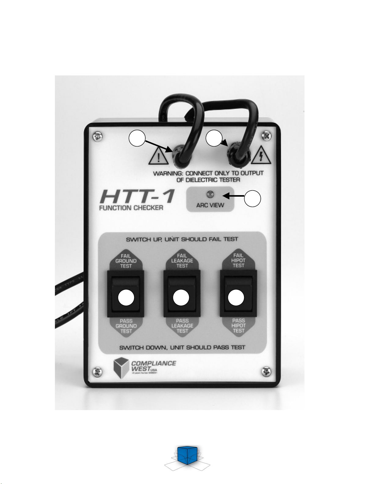
6 5 4
3
1 2
Figure 1: HTT-1 Front Panel Features
5
Page 11

Item Name Function
Return Banana
1
2
Receptacle
Output Banana
Receptacle
3 Arc View
4
5
6
Hipot Test
Switch
Leakage Test
Switch
Ground Test
Switch
Connected to the Return Lead on the Hipot or Ground Continuity
Tester, which is normally connected to dead metal parts of the
equipment undergoing dielectric test.
Connected to the high voltage output of the Hipot Tester being
checked. If a Ground Continuity Tester is being checked, connect to
the high current output.
When Dielectric Breakdown function is being checked, a spark will be
visually demonstrated the breakdown occurred.
When set to FAIL, a dielectric breakdown will be simulated and a spark
can be seen in the Arc View window. When set to PASS, a normal
passing result is simulated. Used for Dielectric Testers only.
When set to FAIL, an excess leakage condition is simulated and the
tester should stop testing and indicate a failure. When set to PASS, a
normal passing result is simulated. Used for Dielectric Testers only.
When set to FAIL, an open ground is simulated and the tester should
stop testing and indicate a failure. When set to PASS, a normal passing
result is simulated.
Table 2: HTT-1 front panel Controls, Indicators, and Connectors
6
Page 12

Section 4
Troubleshooting the HTT-1
The HTT-1 does not require calibration. If the HTT-1 does not operate as described in the
Theory of Operation section, and the equipment connected to the HTT-1 has been verified to be
in good working condition, then the HTT-1 should be returned to Compliance West USA for
inspection and/or repair.
Table 3 shows expected results for a known good hipot tester for all recommended operating
modes.
Switch designation / Switch position
GROUND LEAKAGE HIPOT
PASS PASS PASS
FAIL PASS PASS
PASS FAIL PASS
PASS PASS FAIL
Table 3: HTT-1 Normal operating modes and expected results.
No failure: the tester connected to the HTT-1
should indicate test completion with a passing
Ground Fail: the tester connected to the HTT-1
should indicate a “ground open” or “ground
Leakage Fail: the tester connected to the HTT-
1 should indicate an “excess leakage” or
Hipot Fail: The tester connected to the HTT-1
should indicate a “hipot fail” or “dielectric
failure”. The high-voltage arc that occurs to
create the simulated test failure is visible
through the ARC VIEW window.
Operating mode
result.
fail” condition.
“excess current” failure.
7
Page 13

Section 5
Technical Assistance
For Technical Assistance
Phone: (800) 748-6224
Technical Assistance is available from Compliance West USA between
the hours of 8:30 AM and 4:30 PM Pacific Time Monday through
Friday.
Compliance West USA
2120 Jimmy Durante Blvd., Suite 124
Del Mar, CA 92014
Phone: (858) 481-6454
FAX: (858) 481-8527
8
 Loading...