

Complete Control MRF-350i Installation Manual
MRF-350i Installation Manual
Optimizing Narrow Band Reception with
the RFX-250i and MSC System Remotes

MRF-350i Installation Manual ©2006 - 2013 Universal Remote Control, Inc.
The information in this owner’s manual is copyright protected. No part of this manual may
be copied or reproduced in any form without prior written consent from Universal
Remote Control, Inc.
UNIVERSAL REMOTE CONTROL, INC. SHALL NOT BE LIABLE FOR OPERATIONAL,
TECHNICAL OR EDITORIAL ERRORS/OMISSIONS MADE IN THIS MANUAL.
The information in this owner’s manual may be subject to change without prior notice.
Complete Control is a registered trademark of Universal Remote Control, Inc.
All other brand or product names are trademarks or registered trademarks of their
respective companies or organizations.

TABLE OF CONTENTS
Introduction 1
Features and Benefits 2
Parts Guide 2
Optimizing Range and Reliability 3
Connecting IR and Setting Output Levels 6
Front Blaster Overload 7
Disabling the Front Blaster - Step by Step via PC 7
Controlling An Array of Identical Components or Zones 8
Identical Components/Zone - Step by Step via PC 8
Programming For Multiple Equipment Locations 11
Frequently Asked Questions 12
Specifications 12
Limited Warranty Statement 13
End User Agreement 15
Regulatory Information to the user 16
Precautions and Information Concerning
Rechargeable Lithium-Ion Batteries 17
MRF-350i BASE STATION
Page 1
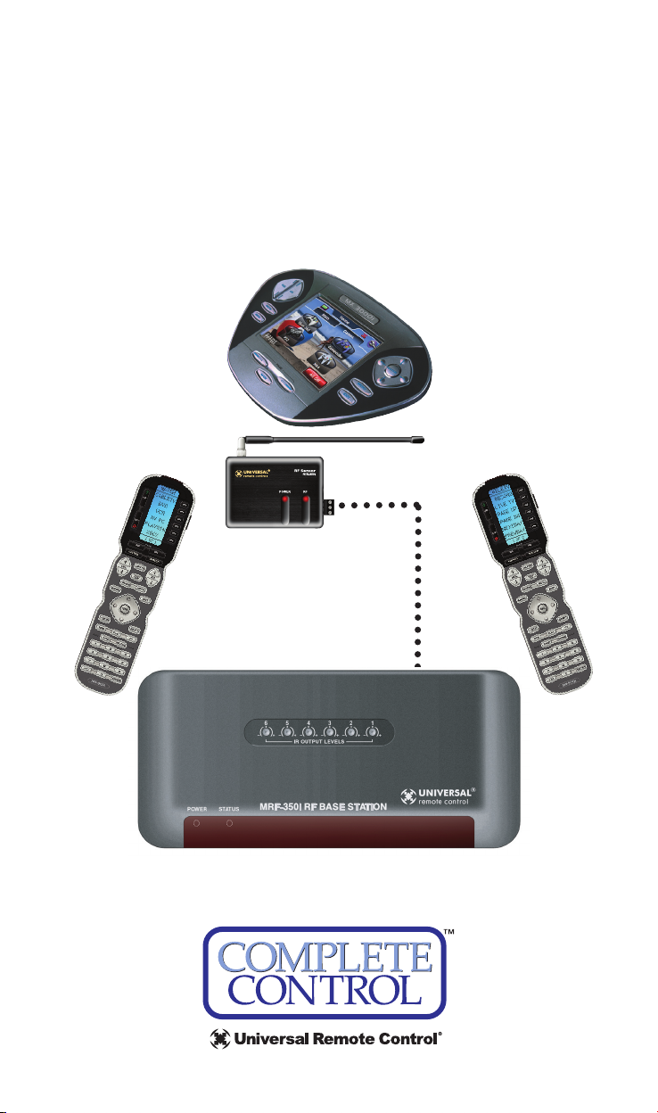
1. MSC System remote controls send
radio waves in every direction, so
your client enjoys “No More Pointing”
operation!
Introduction
The MRF-350i base station is an “addressable” base station like the MRF-350.
RF Addressing gives you the ability to control as many as 90 identical components
throughout a house. However, the MRF-350i includes an RFX-250i, which is
tuned to 433.92 MHz, so is only compatible with “i” series remote controls.
2. The RFX-250i RF Sensor can be freely positioned out of way of
the interference the A/V components create, connecting to the
MRF-350i via a 10’ cable (which can be extended).
3. The MRF-350i’s built-in Front Blaster sends commands to
components in the same cabinet space as the MRF-350i.

MRF-350i BASE STATION
Page 2
Features and Benefits
Interference Rejection and Extended RF Range via RFX-250i
The MRF-350i receives RF (radio frequency) signals via the RFX-250i RF Sensor.
The RFX-250i displays RF interference via a bright red LED, which flickers when
interference is present. Simply relocate the RFX-250i out of the interference.
Expand Range by Adding RFX-250i RF Sensors in Remote Areas
The MRF-350i can power up to three RFX-250i RF Sensors connected in parallel
to the RF Input connector.
Variable IR Output Matches Rear Panel IR Inputs
The MRF-350i is equipped with adjustable IR line outputs, each output can be
individually matched to rear panel IR inputs on any component that is designed
to be operated by a standard IR repeater. The outputs utilize a 3.5mm jack.
Up To Fifteen Equipment Locations With Identical Components
Each MSC System remote is “addressable.” They can be programmed to specifically
control components in a particular room by installing a base station at each
location. In operation it’s simple: when you select a device located in the Den,
the MX series remote only sends commands to the Den. When you select a
device located in the Family Room, the MX-3000i only sends commands to it.
A Single MRF-350i Can Control an Array of Identical Components
or Identical Zones of a Multi Zone Preamp/Matrix Switcher
Each MRF-350i has six “addressable” IR Line Outputs. For example, you can control
up to six identical TV’s with one MRF-350i or route volume commands for a
specific zone to a particular zone IR input on a multi-zone preamp. If you have
more than six identical components or zones, up to 15 additional MRF-350is can
be installed to control them (thus allowing up to 90 identical components or
zones in one house).
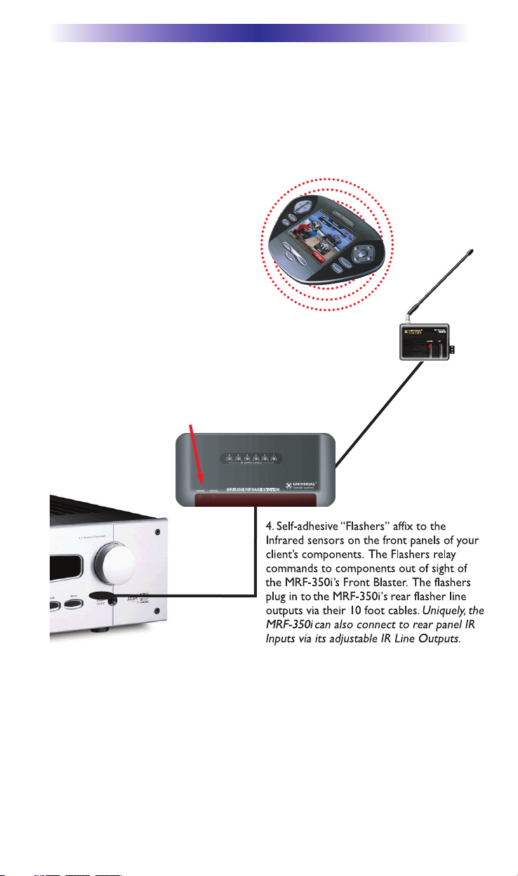
IR Input for Keypads or IR Repeater Systems
The MRF-350i rear panel IR input will relay IR Data from IR repeaters or
Multi-Zone Keypads to all IR line outputs (does not support IR routing). The 5V,
100 milliamp output will directly power some brands and models of keypad
directly.
Parts Guide
The MRF-350i RF Base Station includes:
1 - RFX-250i RF Sensor with integrated
antenna
1 - Mounting plate for RFX-250i
1 - MRF-350i Base Station
1 - Mounting Plate for wall mounting the
MRF-350i
8 - Screws for wall mounting the two
mounting plates
1 - 9V-300mA Power Supply
6 - Visible Flashers with 10 foot plug in cables.
6 - Extra self adhesive pads for Emitters
1 - 12’Connecting Cable
1 - Adjustment Tool (Screwdriver for RF ID
and IR level adjustment)
2 - Depluggable screw connectors for RF
connections when extending wires.
MRF-350i BASE STATION
Page 3
Optimizing Range and Reliability
1. Power on all AV components, lower all dimmers to 50% and power on
anything that may create RF Interference (particularly devices with high
speed microprocessors or hard drives).
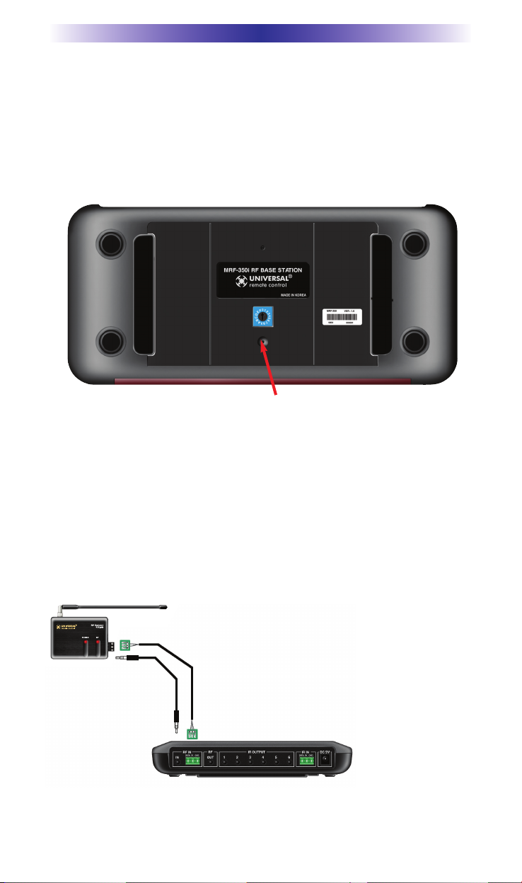
2. Check that the address wheel on the bottom of the MRF-350i is set to
ID#0 (the interference “sniffing” position).
3. Connect the MRF-350i to its DC wall adapter and plug the wall adapter
into a live AC outlet. Place the MRF-350i in a convenient central location
in the equipment rack. Unlike an MRF-250i, the MRF-350i can be placed
next to components with hard drives or high speed microprocessors.
There is no RF circuitry inside the MRF-350i itself.
4. Connect the RFX-250i to the MRF-350i’s RF INPUT. You can connect to
either the screw connector or the jack as shown:
Slide off the mounting plate to reveal the RF ID# rotary switch. Check that the arrow
pointer in the center of the wheel is pointed to 0, the default “interence sniffing” position.
If it is not, use a small flat blade screwdriver (included) to set the RF ID# to 0.
When connecting a single RFX-250i to the MRF-350i
utilize the cable with 3.5 mm plugs on both ends.
When you need a longer wire or are connecting up
to three RFX-250is, use a cable with tinned ends.
Cable can be extended as much as 200’, then connected
to the removable screw connector plugs. If you use
CAT 5 connect four conductors to GND (one from
each twisted pair) and connect the remaining
conductors two at a time to 5V and DATA.
MRF-350i BASE STATION
Page 4
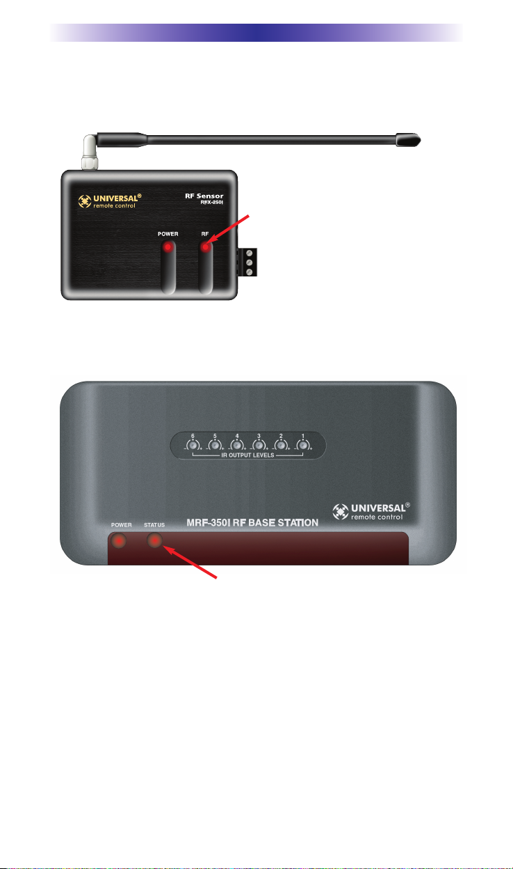
5. Observe the RF LED of the RFX-250i. Cup your hand over the RFX-250i’s
RF LED. If it is glowing or flickering you must relocate the RFX-250i to a
location where the LED doesn’t flicker.
6. Observe the STATUS LED of the MRF-350i. It is a little more sensitive
than the RFX-250i. If you see any flickering of this LED, move the
RFX-250i to a new location.
If your installation location simply doesn’t offer you any choice and you
are detecting interference everywhere you place the RFX-250i you have
three last resort options:
a. Remove the RFX-250i’s antenna. This will reduce the range
enormously, but may still be enough for this client.
b. Extend a wire to another room. Try this over the floor first,
before attempting to conceal the wire.
c. Admit defeat and install a “pointing again” IR repeater system.
If no buttons are pressed on any remote
control, no valid RF transmissions
are
being received. The flickering or glowing
RF LED warns you that the RFX-250i is
detecting RF interference generated or
reflected near this location. MOVE the
RFX-250i to a new location.
The flickering or glowing STATUS LED warns you that the RFX-250i is detecting RF
interference generated or reflected near this location. MOVE the RFX-250i to a new
location.
MRF-350i BASE STATION
Page 5
7. Once you have found a location that is absolutely
clean with everything on, test to see if the range is
adequate and that macro reliability is perfect.
Start with the antenna angle set to 45 degrees and
positioned so that the long side of the antenna is
facing the customer’s favorite seating position.
When testing, set both the remote and the MRF-350i
to the same VALID RF ID#. Keep in mind that zero (0) is not a valid RF
ID#. Watch the STATUS LED on MRF-350i - it should light every time
you press a button on the remote. This will tell you that the signal was
received and understood. You can ignore the RF LED on the RFX-250i
(it only indicates that a signal was received, not that it was understood).
8. If the range is inadequate,
you may extend wire to any
area that is not giving good
results and place an additional
RFX-250i in that area. Up
to
three RFX-250is can be
connected to one MRF-350i.
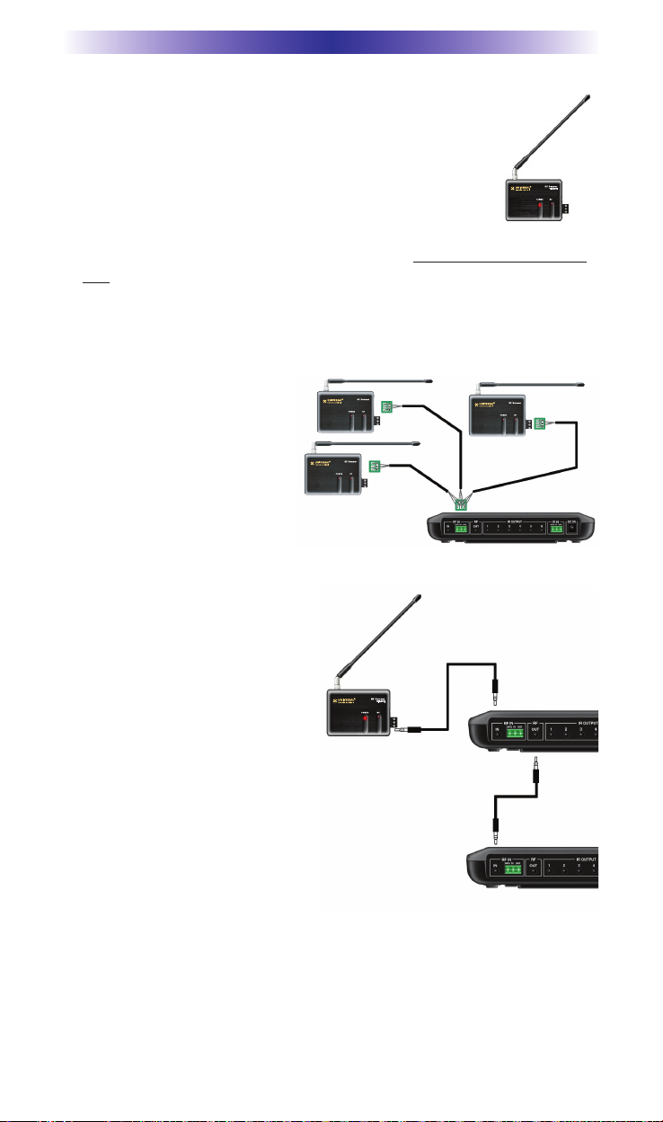
9. Should you need more than six
IR Outputs, connect as many as
three different MRF-350is to one
RFX-250i in a daisy chain using
the supplied cable.
To preserve addressibility, set
each MRF-350i to a different RF
ID number. Remember “0”
(zero) is not a valid RF ID.
RFX-250iRFX-250i
RFX-250iRFX-250i
RFX-250iRFX-250i
 Loading...