

Page 1
Page 2

Copyrights © 2002 Compex Systems Pte Ltd
All Rights Reserved
This document contains information, which is protected by copyright. Reproduction, adaptation
or translation without prior permission is prohibited, except as allowed under the copyright
laws.
Trademark Information
®
Compex
, ReadyLINK® and MicroHub® are registered trademarks of Compex, Inc. Microsoft
Windows and the Windows logo are the trademarks of Microsoft Corp. NetWare is the
registered trademark of Novell Inc. All other brand and product names are trademarks or
registered trademarks of their respective owners.
Notice: Copyrights © 2002 by Compex, Inc. All rights reserved. Reproduction, adaptation, or
translation without prior permission of Compex, Inc. is prohibited, except as allowed under the
copyright laws.
Manual Revision by Ong
Manual Number: U-0356-V1.1C Version 1.1, October 2002
Disclaimer
Compex, Inc. provides this manual without warranty of any kind, either expressed or implied,
including but not limited to the implied warranties of merchantability and fitness for a particular
purpose. Compex, Inc. may make improvements and/or changes to the product and/or
specifications of the product described in this manual, without prior notice. Compex, Inc will
not be liable for any technical inaccuracies or typographical errors found in this guide. Changes
are periodically made to the information contained herein and will be incorporated into later
versions of the manual. The information contained is subject to change without prior notice.
Your Feedback
We value your feedback. If you find any errors in this user’s manual, or if you have suggestions
on improving, we would like to hear from you. Please contact us at:
Telephone: (65) 63810139
Fax: (65) 62809947
Email: feedback@compex.com.sg
i
Page 3

FCC NOTICE
This device has been tested and found to comply with the limits for a Class B digital device,
pursuant to Part 15 of the FCC Rules. These limits are designed to provide reasonable
protection against harmful interference in a residential installation. This device generates, uses
and can radiate radio frequency energy and, if not installed and used in accordance with the
instructions, may cause harmful interference to radio communications. However, there is no
guarantee that interference will not occur in a particular installation. If this device does cause
harmful interference to radio or television reception, the user is encouraged to try to correct the
interference by one or more of the following measures:
• Reorient or relocate the receiving antenna.
• Connect the computer into an outlet on a circuit different from that to which the receiver is
connected.
• Increase the separation between the computer and receiver.
• Consult the dealer or an experienced radio/TV technician for help.
Caution: Exposure to Radio Frequency Radiation.
To comply with the FCC RF exposure compliance requirements, the following antenna
installation and device operating configurations must be satisfied:
1. For configurations using the integral antenna, the separation distance between the antenna(s)
and any person’s body (including hands, wrists, feet and ankles) must be at least 2.5cm (1
inch).
2. For configurations using an approved external antenna, the separation distance between the
antenna and any person’s body (including hands, wrists, feet and ankles) must be at least
20cm (8 inch).
The transmitter shall not be collocated with other transmitters or antennas.
Caution: Any changes or modifications not expressly approved by the grantee of this device
could void the user's authority to operate the equipment.
FCC Compliance Statement: This device complies with Part 15 of the FCC Rules. Operation
is subject to the following two conditions:
1. This device may not cause harmful interference, and
2. This device must accept any interference received, including interference that may cause
undesired operation.
ii
Page 4

Declaration of Conformity
Compex, Inc. declares the following:
Product Name: Compex 11Mbps Wireless LAN Access Point
Model No.: WP11A+ conforms to the following Product Standards:
This device complies with the Electromagnetic Compatibility Directive (89/336/EEC) issued by
the Commission of the European Community.
Electromagnetic Interference (Conduction and Radiation)
Electromagnetic Immunity
Power Line Harmonics
Power Line Flicker
: EN 55024 (IEC61000-4-2,3,4,5,6,8,11)
: EN 61000-3-2 (IEC610000-3-2)
: EN 61000-3-3 (IEC610000-3-3)
: EN 55022 (CISPR 22)
Therefore, this product is in conformity with the following regional standards: FCC Class B
following the provisions of FCC Part 15 directive; CE Mark following the provisions of the
EC directive.
This Class B digital apparatus complies with Canadian ICES-003.
Declaration of Conformity
Compex, Inc. declares the following:
Product Name: Compex 11Mbps Wireless LAN Access Point
Model No.: WP11A+ conforms to the following Product Standards:
This device complies with the R&TTE Directive (1999/5/EC) issued by the Commission of the
European Community. Compliance with this directive implies conformity to the following
European Norms (in brackets are the equivalent international standards.)
Product Safety
Technical requirements for radio equipment
General EMC requirements for radio equipment
: EN 60950 (IEC60950)
: EN 300 328-1/2
: ETS 300 826 or ETSI EN 301 489-1/17
Therefore, this product is in conformity with the following regional standards: FCC Class B
following the provisions of FCC Part 15 directive; CE Mark following the provisions of the
EC directive.
This Class B digital apparatus complies with Canadian ICES-003.
st
October 2002
31
iii
Page 5
Technical Support Information
The warranty information and registration form are found in the Quick Install Guide.
For technical support, you may contact Compex or its subsidiaries. For your convenience, you
may also seek technical assistance from the local distributor, or from the authorized
dealer/reseller that you have purchased this product from. For technical support by email, write
to support@compex.com.sg.
Refer to the table below for the nearest Technical Support Centers:
Technical Support Centers
Contact the technical support center that services your location.
U.S.A., Canada, Latin America and South America
Write
Call
Fax
Write
Call
Fax
Compex, Inc.
4051 E. La Palma, Unit A
Anaheim, CA 92807, USA
Tel:
Tel:
Fax:
BBS:
+1 (714) 630-7302 (8 a.m.-5 p.m. Pacific time)
+1 (800) 279-8891 (Ext.122 Technical Support)
+1 (714) 630-6521
+1 (714) 630-2570 (24-hour access)
Europe
ReadyLINK Networktechnology Gmbh
Albert Einstein Straβe 34/M21
63322 Rödermark, Germany
Tel:
Fax:
BBS:
Support Email: readylink@compex.com.sg
+49 (0) 6074 - 98017 (8 a.m.-5 p.m. local time)
+49 (0) 6074 - 90668
+49 (0) 6074 - 93974 (24-hour access)
Asia, Australia, New Zealand, Middle East
Write
Call Tel:
Fax
Internet
access/
Website:
Compex Systems Pte Ltd
135, Joo Seng Road #08-01, PM Industrial Building
Singapore 368363
Tel:
Fax:
BBS:
E-mail:
FTPsite:
http://www.cpx.com or http://www.compex.com.sg
and the rest of the World
(65) 6286-1805 (8 a.m.-5 p.m. local time)
(65) 6286-2086 (Ext.199 Technical Support)
(65) 6283-8337
(65) 6282-8854 (24-hour access)
support@compex.com.sg
ftp.compex.com.sg
iv
Page 6
About This Document
The product described in this document, Compex NetPassage Series, Compex WP11A+ is a
licensed product of Compex Systems Pte Ltd. This document contains instructions for
installing, configuring and using Compex WP11A+. It also gives an overview of the key
applications and the networking concepts with respect to the product.
This documentation is for both Network Administrators and end users who possess some basic
knowledge of networking structures and protocols.
This document makes the assumptions that a host computer is installed with TCP/IP and is
already up & running with Internet access. Procedures for Windows 98/2000/XP operating
systems are included in this document. However, for other operating systems, you may need to
refer to your operating system’s documentation for networking.
How to Use this Document
The document is written in such a way that you as a user will find it convenient to find specific
information pertaining to the product. It comprises of chapters that explain in details the
installation and configuration of Compex WP11A+.
Firmware
This manual is written based on Firmware version 2.86 Build 0919.
Conventions
In this document, special conventions are used to help and present the information clearly. The
Compex 11Mbps PCMCIA Wireless LAN Access Point is often referred to as Compex
WP11A+ in this document. Below is a list of conventions used throughout.
NOTE
This section will consist of important features or instructions
CAUTION
This section concerns risk of injury, system damage or loss of data
WARNING
This section concerns risk of severe injury
References on Menu Command, Push Button, Radio Button, LED and Label appear in Bold.
For example, “Click on the “Ok” button”
v
Page 7

Table of Contents
Copyrights © 2002 Compex Systems Pte Ltd.................................................................. i
Trademark Information ................................................................................................... i
Disclaimer......................................................................................................................i
Your Feedback ............................................................................................................... i
FCC NOTICE................................................................................................................. ii
Declaration of Conformity............................................................................................... iii
Technical Support Information........................................................................................ iv
About This Document..................................................................................................... v
How to Use this Document ............................................................................................. v
Firmware........................................................................................................................v
Conventions.................................................................................................................... v
Chapter 1 Product Overview.............................................................. 1
1.1 Introduction ........................................................................................................... 1
1.2 Overview............................................................................................................... 1
1.3 Features and Benefits............................................................................................. 2
1.3.1 IEEE 802.11 Compliant ............................................................................. 2
1.3.2 11Mbps High Rate Communication............................................................ 2
1.3.3 Wire Equivalent Privacy (WEP)................................................................. 2
1.3.4 Wireless/Ethernet Transparent Bridging..................................................... 2
1.3.5 Broadband Internet Sharing........................................................................ 2
1.3.6 LAN-to-LAN Bridging ............................................................................... 3
1.3.7 Upgradeable Firmware............................................................................... 3
1.3.8 Web-Based Interface .................................................................................. 3
1.4 Panel Views........................................................................................................... 3
1.5 Panel Description................................................................................................... 5
1.6 Technical Specifications ........................................................................................ 7
Chapter 2 Getting Started................................................................... 9
2.1 Package Content .................................................................................................... 9
2.2 Setup Considerations ............................................................................................. 9
2.2.1 Software requirements ............................................................................... 9
2.2.2 Hardware requirements.............................................................................. 9
Chapter 3 Hardware Installation........................................................ 10
Chapter 4 Software Configuration...................................................... 12
4.1 Login into Web-based Interface.............................................................................. 12
4.1.1 AP Bridge and AP Client Mode.................................................................. 15
Page 8

Table of Contents
4.1.2 Gateway and Wireless Routing Client Mode .............................................. 15
Chapter 5 Configure Compex WP11A+ Using Web Interface........... 17
5.1 Changing the IP Address of Compex WP11A+....................................................... 18
5.2 Configuring DHCP Server...................................................................................... 18
5.3 Setting up Wireless Per Group Pseudo LAN using AP Bridge Mode....................... 20
5.4 Setting up Wireless LAN-to-LAN Bridge Network using AP Client Mode.............. 28
Chapter 6 Setting up Wide Area Network using Gateway Mode....... 32
6.1 Selecting the Right connection for your Broadband Internet Service ....................... 32
6.2 Setup on Compex WP11A+ for Broadband Internet Access .................................... 33
6.3 Configure Compex WP11A+ using Web Interface.................................................. 35
6.3.1 Advanced configuration in Gateway Mode.................................................. 38
Chapter 7 Setting up WAN using Wireless Routing Client ................ 39
7.1 Setting up Compex WP11A+ as Wireless Routing Client ....................................... 39
7.2 Configuring Compex WP11A+ as Wireless Routing Client through Web Interface . 41
Chapter 8 Configuration on Various WAN Type............................... 44
8.1 Configuring Static IP Connection ........................................................................... 44
8.2 Configuring Dynamic IP Connection ...................................................................... 46
8.2.1 How to configure Singapore Cable Vision (SCV) Service ........................... 46
8.2.2 How to Configure @HOME Cable Service................................................. 47
8.3 Configuring PPP over Ethernet Session (PPPoE).................................................... 48
8.3.1 How to Configure SingNet, PacNet andQALA DSL Broadband.................. 48
8.4 Configuring for SingTel Magix SuperSurf.............................................................. 50
8.5 Configuring for BigPond Australia (BPA) .............................................................. 51
8.6 Point to Point Tunneling Protocol (PPTP) .............................................................. 53
8.7 JTB BruNet e-Speed.............................................................................................. 55
Chapter 9 Configuring Network Address Translation ....................... 57
9.1 NAT and Virtual Server......................................................................................... 57
9.2 Defining Port-Forwarding Virtual Server ............................................................... 58
9.2.1 When to use Port–Forwarding Virtual Server ............................................. 58
9.3 Configuring Port–Forwarding virtual server with Compex WP11A+....................... 58
9.4 Configuring IP-Forwarding virtual server with Compex WP11A+........................... 60
Page 9

Table of Contents
Chapter 10 Routing............................................................................. 62
10.1 Configuring Routing Protocol................................................................................. 62
10.2 Adding Static Routes ............................................................................................. 62
Chapter 11 Packet Filtering................................................................ 64
11.1 Filtering................................................................................................................. 64
Chapter 12 Remote Management........................................................ 67
12.1 Remote Management ............................................................................................. 67
Chapter 13 Using SYSTEM TOOLS menu........................................ 68
13.1 System Identity...................................................................................................... 68
13.2 Set System Time.................................................................................................... 69
13.3 Firmware Upgrade................................................................................................. 70
13.4 Save or Reset Settings............................................................................................ 71
13.5 Reboot System....................................................................................................... 72
13.6 Change Password................................................................................................... 73
13.7 Logout ................................................................................................................... 74
13.8 Exit uConfig .......................................................................................................... 74
Chapter 14 Using HELP menu ........................................................... 76
14.1 Get Technical Help................................................................................................ 76
14.2 About System ........................................................................................................ 77
14.2.1 AP Bridge/AP Client Mode........................................................................ 77
14.2.2 Gateway Mode........................................................................................... 77
Chapter 15 Hardware Reset of Compex WP11A+ ............................. 78
Appendix I Login to Web-based Interface manually.......................... 79
AI-1 Configuration of Compex WP11A+ using Web-based Interface .............................. 79
Appendix II TCP/IP Configuration ..................................................... 81
AII-1 Adding TCP/IP network protocol for Windows 98/98SE/ME.................................. 81
AII-2 TCP/IP network protocol configuration for Windows XP/2000 ............................... 84
Page 10

Table of Contents
Appendix III Configuration and Commands on Telnet Interface ......... 86
AIII-1 Telnet Interface Confi guration.......................................................................... 86
AIII-2 Command Line Interface Commands Lis t ......................................................... 87
AIII-3 How to r ecover Compe x WP11A+ from failed fir mware ................................... 88
AIII-4 If you have any problem to accessing t o the Internet ......................................... 90
Page 11

Chapter 1 Product Overview
Chapter 1 Product Overview
1.1 Introduction
A wireless network is a convenient way of setting up a network both at home and in the
office. The lack of a physical infrastructure, such as LAN cables, reduces the cost of
implementing a network environment.
As a home user, you can enjoy the freedom to roam around your house and still
maintain connection to your network. Surfing the web, sending e-mail or downloading a
program while in the garden, near your swimming pool or anywhere in your house, is
now a reality.
With the many benefits that a wireless network environment brings, many users are
contemplating of expanding their network environment with wireless devices.
1.2 Overview
Compex WP11A+ is an easy-to-use 11Mbps Wireless LAN Access Point configurable
for four operating modes, namely
• Access Point Bridge
• Access Point Client
• Gateway
• Wireless Routing Client
It supports up to 11Mbps wireless communication on 2.4GHz ISM band using DSSS
(Direct Sequence Spread Spectrum)
1
Page 12

Chapter 1 Product Overview
1.3 Features and Benefits
Compex WP11A+ is designed to give you a complete solution of a wireless network by
establishing connection with a wireless client. The list below identifies some of the
features and benefits of Compex WP11A+.
1.3.1 IEEE 802.11 Compliant
Compex WP11A+ is fully compliant with IEEE 802.11 standard. It divides the
2.4GHz license-free ISM (Industrial, Scientific & Medical) band into 14 sub
channels, where the number of usable channels is subjected to local
regulations of the respective country/region.
1.3.2 11Mbps High Rate Communication
Compex WP11A+ supports IEEE 802.11b high rate communication of up to
11Mbps, and it is backward compatible with the older 2Mbps and 1Mbps
standard.
1.3.3 Wire Equivalent Privacy (WEP)
Compex WP11A+ uses a private encryption key to ensure data security. This
is commonly referred to as Wire Equivalent Privacy (WEP). Compex
WP11A+ supports 64-bit and 128-bit WEP selectable via its web-based
configuration interface.
1.3.4 Wireless/Ethernet Transparent Bridging
Compex WP11A+ can be used as a Wireless Access Point functioning as a
transparent Bridge between the Wireless and Ethernet segments. It shares
resources for Microsoft and Novell Networks by using TCP/IP & IPX
respectively as the protocol for communication.
1.3.5 Broadband Internet Sharing
Compex WP11A+ may be configured to Gateway Mode. This allows sharing
of your broadband Internet access with your wireless clients. In addition, it
supports advanced features such as Virtual servers, Time-based Access
Management, IP Packet Filtering & Remote Management.
2
Page 13
Chapter 1 Product Overview
1.3.6 LAN-to-LAN Bridging
Compex WP11A+ may also be configured as an Extended Service Set (ESS)
Client, working in conjunction with another ESS Access Point (AP) to
function as a LAN-to-LAN Wireless Bridge.
1.3.7 Upgradeable Firmware
Compex WP11A+ is specially designed with a flash ROM that allows you to
update the Compex WP11A+ with the latest firmware release via a web-based
configuration interface.
1.3.8 Web-Based Interface
Compex WP11A+ is integrated with an embedded HTTP server facilitating a
multi-platform web-based configuration interface that requires only a JAVAenabled web browser.
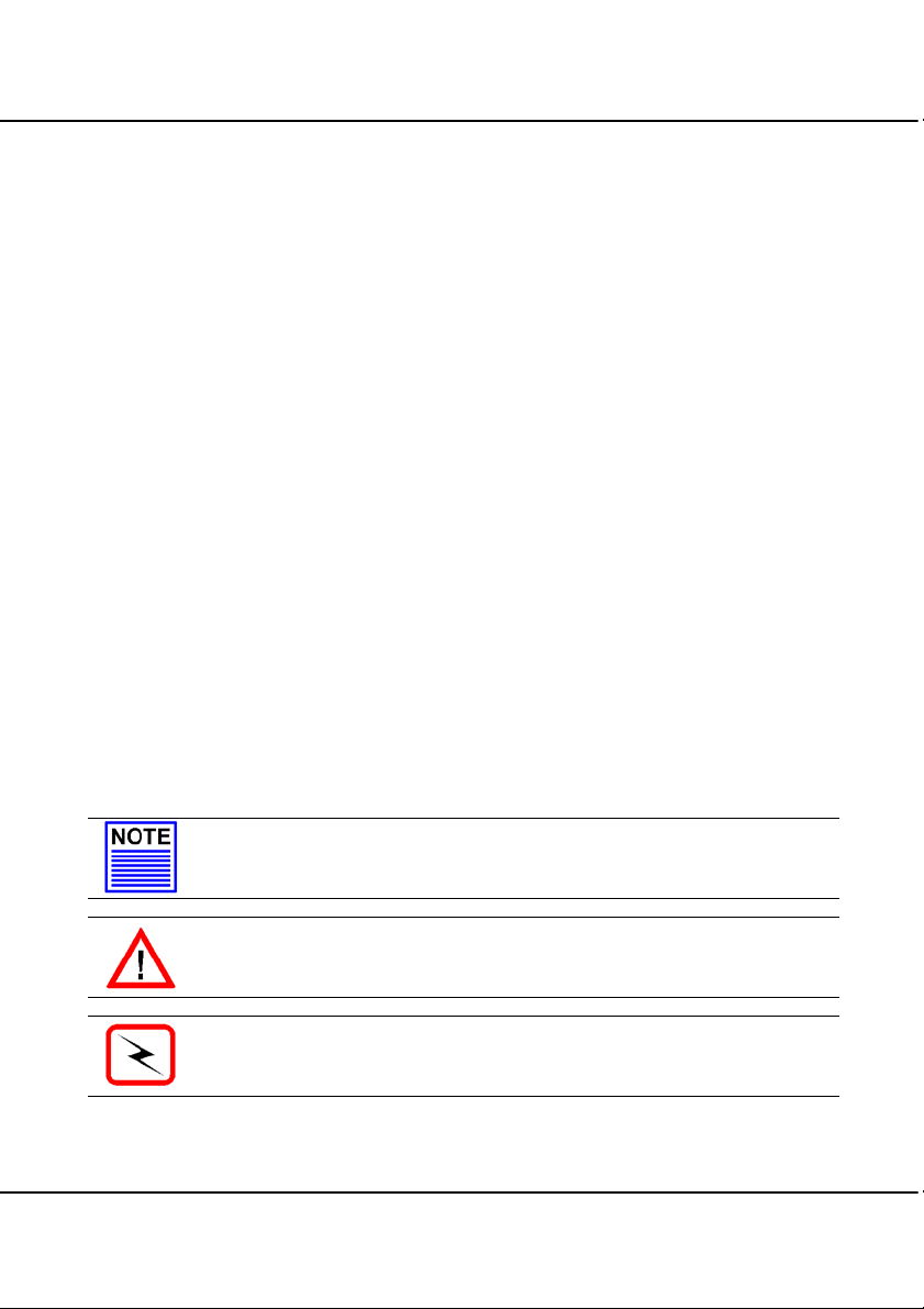
1.4 Panel Views
7
1 2 3 4 5 6 9
Figure 1.4a Front view of Compex WP11A+
8
3
Page 14
Chapter 1 Product Overview
g
10
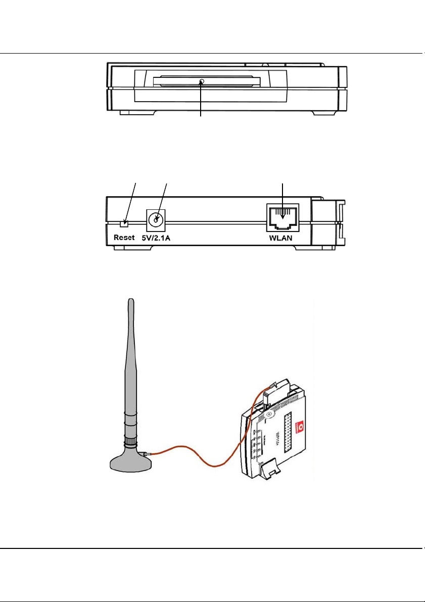
Figure 1.4b Side view of Compex WP11A+ (Section #1)
13 11 12
Figure 1.4c Side view of Compex WP11A+ (Section #2)
Connecting WA-HGA-5+ to WP11A+ will
increase the wireless network covera
e.
WA-HGA-5+
(sold separately)
Figure 1.4dConnection to indoor antenna
4
Page 15
Chapter 1 Product Overview
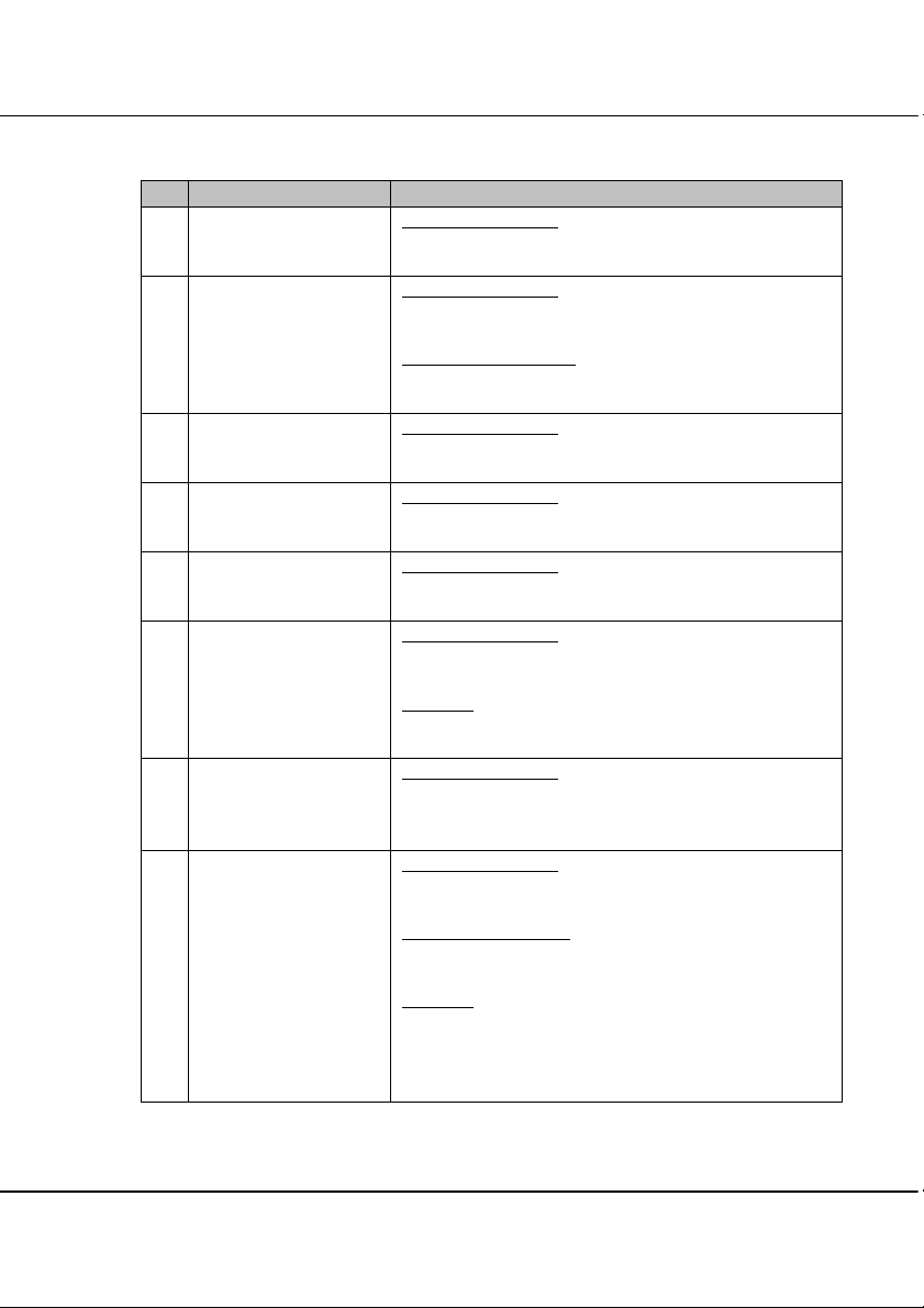
1.5 Panel Description
Indicator Description
1 Power LED Steady Green Light
Power is supplied to Compex WP11A+.
2 WLAN LED Steady Green Light
A link is connected.
Flashing Green Light
An activity is going on.
10M LED
3
4 100M LED Steady Green Light
5 COL LED Steady Green Light
6 FDX LED Steady Green Light
Steady Green Light
LAN connecting at 10Mbps.
LAN connecting at 100Mbps.
Collision occurs at the network segment.
Network is in Full Duplex Mode.
No Light
Network is in Half Duplex Mode.
7 WLAN Speed LED
Total 5 LEDs
8 DIAG LED Steady Green Light
Steady Green Light
More LEDs lighting up indicate a higher speed of
data transmission.
Compex WP11A+ is booting and loading firmware.
Flashing Green Ligh
Firmware is corrupted.
No Light
Firmware has been completely downloaded onto the
Compex WP11A+. The device is connected to the
network.
t
5
Page 16
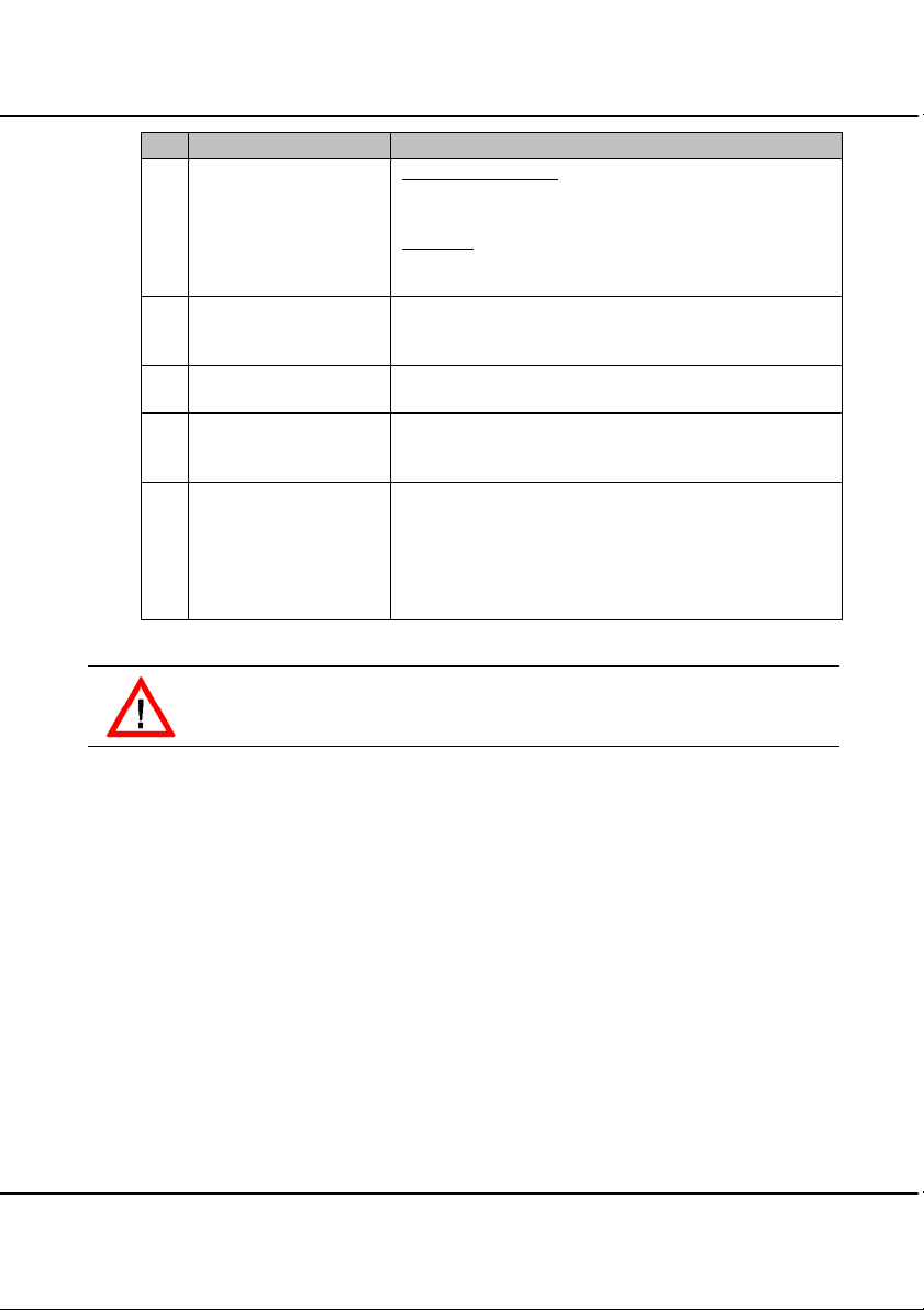
Chapter 1 Product Overview
Indicator Description
9 AP Mode LED Steady Green Light
The device is in AP Bridge Mode or AP Client Mode.
No Light
The device is in Gateway mode.
10 Wireless Interface Built-in 11Mbps Wireless LAN PCMCIA Card to
support wireless client.
11 5V DC/2.1A Accepts 5V DC/2.1A input.
12 RJ45 Ethernet Port 10Base-T or 100-Base-TX Port connects to cable
modem or xDSL modem.
13 Reset Button Compex WP11A+ will reboot the device, set to
default setting or switch between the selections of
work mode.
For more details please refer to “Hardware Reset of
Compex WP11A+” on Page 78.
CAUTION
Do not remove the wireless Interface Card from Compex WP11A+.
6
Page 17
Chapter 1 Product Overview
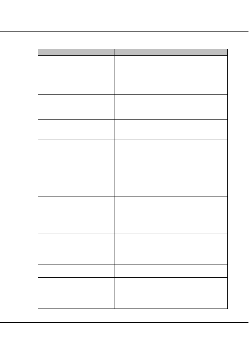
1.6 Technical Specifications
Items Specifications
Industry Standards
Safety Certifications CE Mark, FCC Class B, Gost, C-Tick, UL
Radio Technology Direct Sequence Spread Spectrum (DSSS)
• IEEE 802.3 10Base-T;
• IEEE 802.3u 100Base-TX;
• IEEE 802.11 DSSS;
• IEEE 802.11b High Rate;
• IEEE 802.1d LAN Bridging
Frequency Band
Data Rate
Private Encryption 64-bit or 128-bit WEP (selectable)
Operating Mode AP Mode, AP Client Mode, Gateway Mode and
AP Mode
WAN Interface
Supported Protocol
Wireless Pseudo VLAN
Function
Client Mode
WAN Interface
Supported Protocol
Function
Firmware Upgrade Yes
Antenna Diversity PCB Micro Strip Antenna
Roaming Unrestricted client roaming across multiple
• 2400 ~ 2483.5MHz (USA, Canada)
• 2400 ~ 2497MHz (Europe, Asia)
• CCK - 11Mbps, 5.5Mbps
• DQPSK - 2Mbps
• DBPSK - 1Mbps
Wireless Routing Client (selectable)
RJ45 10/100Mbps port
IP, IPX, Ne tBEUI
Per Node & Per Group
Wireless to Ethernet Bridging
RJ45 10/100Mbps port
IP, IPX
Ethernet to Ethernet Wireless Bridging
access points
7
Page 18

Chapter 1 Product Overview
Items Specifications
Media Access Method Carrier Sense Multiple Access with Collision
Gateway Mode (Selectable)
Wired Interface
Wireless Pseudo VLAN
Private Subnet
Built-In DHCP Server
Virtual Server
Time-based Access Control
IP Packet Filtering
Router’s Clock
Configuration Interface
Remote Router Management
Operating Channels 11 channels
Dimension (L x W x H) 122mm x 119mm x 22mm (L x W x H)
Environmental Requirement
Temperature
Humidity
Avoidance (CSMA/CA)
RJ45 10/100Mbps port
Per Node & Per Group
All Classful/Classless subnet
Yes (with DHCP reservation)
Port Forwarding and IP Forwarding
Yes
Yes
Yes
Web-based & TELNET Command Console
Via HTTP or TELNET session
Operating: 0°C to 40°C
Storage: -20°C to 70°C
Operating: 10%RH to 80%RH
Storage: 5%RH to 90%RH
8
Page 19

Chapter 2 Getting Started
Chapter 2 Getting Started
This chapter outlines the basic requirements before you begin any installation and configuration
of Compex WP11A+.
2.1 Package Content
Thank you for purchasing Compex WP11A+. The package should contain the
following:
• Compex WP11A+ unit
• Compex WP11A+ switching Power Adapter
• Quick Install Guide with warranty registration
• CD User’s Manual with Utility Configuration Software
• Clip holder stand
2.2 Setup Considerations
The following are the setup considerations you need to take note of before connecting
the Compex WP11A+ to your network:
2.2.1 Software requirements
• Windows 95/98/98SE/ME/NT/2000/XP
• Web Browser – Microsoft IE V4.0 or higher, Netscape Communicator
V4.06 or higher
• 2 MB of hard disk space
• Check your LAN configurations and IP addresses. Confirm whether they
are Dynamic or Static IP addressing
2.2.2 Hardware requirements
• PCs attached with wireless devices
• Ethernet-ready PC with TCP/IP protocol installed & configured for
Internet access
• RJ-45 cable
9
Page 20
Chapter 3 Hardware Installation
Chapter 3 Hardware Installation
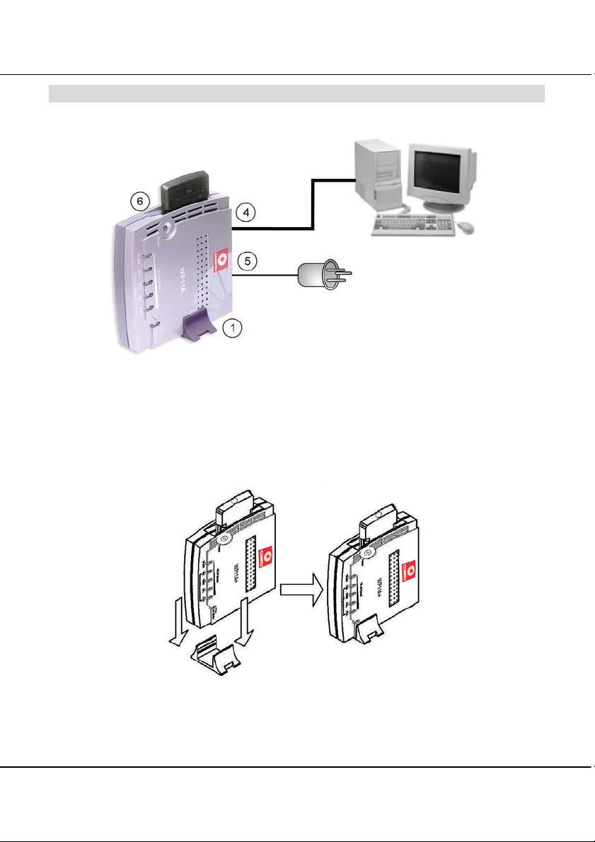
Figure 3a Compex WP11A+ Connections
To begin setting up the Compex WP11A+, please follow the steps listed below:
1. Snap the Compex WP11A+ onto the clip holder stand as shown in Figure 3b.
Slide it into the slot of the
other clip holder stand to
place side by side.
Clip it directly onto the
ventilation hole located at the
back of the device.
Figure 3b Illustration on using Clip holder Stand
10
Page 21

Chapter 3 Hardware Installation
2. Place the Compex WP11A+ in a well ventilated area.
3. Place the device in a standing position.
4. Connect your PC to the Ethernet port of Compex WP11A+ using an MDIX UTP RJ45
cable. Please note that before your PC can access to the Internet, the NIC adapter and
TCP/IP protocol have to be installed and configured first.
5. Plug the AC power adapter. Please use only the correct power adapter supplied by Compex.
6. Check if the power LED is lighted up.
11
Page 22

Chapter 4 Software Configuration
Chapter 4 Software Configuration
After setting up the hardware, install a browser on the PC or workstation. Make sure that the
TCP/IP protocol is installed and configured for Internet access. Please refer to Appendix II.
4.1 Login into Web-based Interface
Compex has developed an utility configuration software, uConfig, that provides hasslefree access to the web-based configuration interface. The uniqueness of this program is
that it does not require any alteration to the TCP/IP configuration on your computer.
Connect the WP11A+ to your computer via a crossover UTP cable.
As pre-configuration of TCP/IP is not required, you just simply activate the program to
get to the configuration page.
To login into Compex WP11A+’s web-based interface,
1. Insert the Product CD provided into your CD-ROM. This will automatically open
up the Welcome Page.
2. Click on the Drivers and Utilities option and select uConfig program.
NOTE
In the event that the program cannot be found, please explore this directory
path, X:\utility\ (where X is the CD-ROM drive) to access the program.
12
Page 23
Chapter 4 Software Configuration
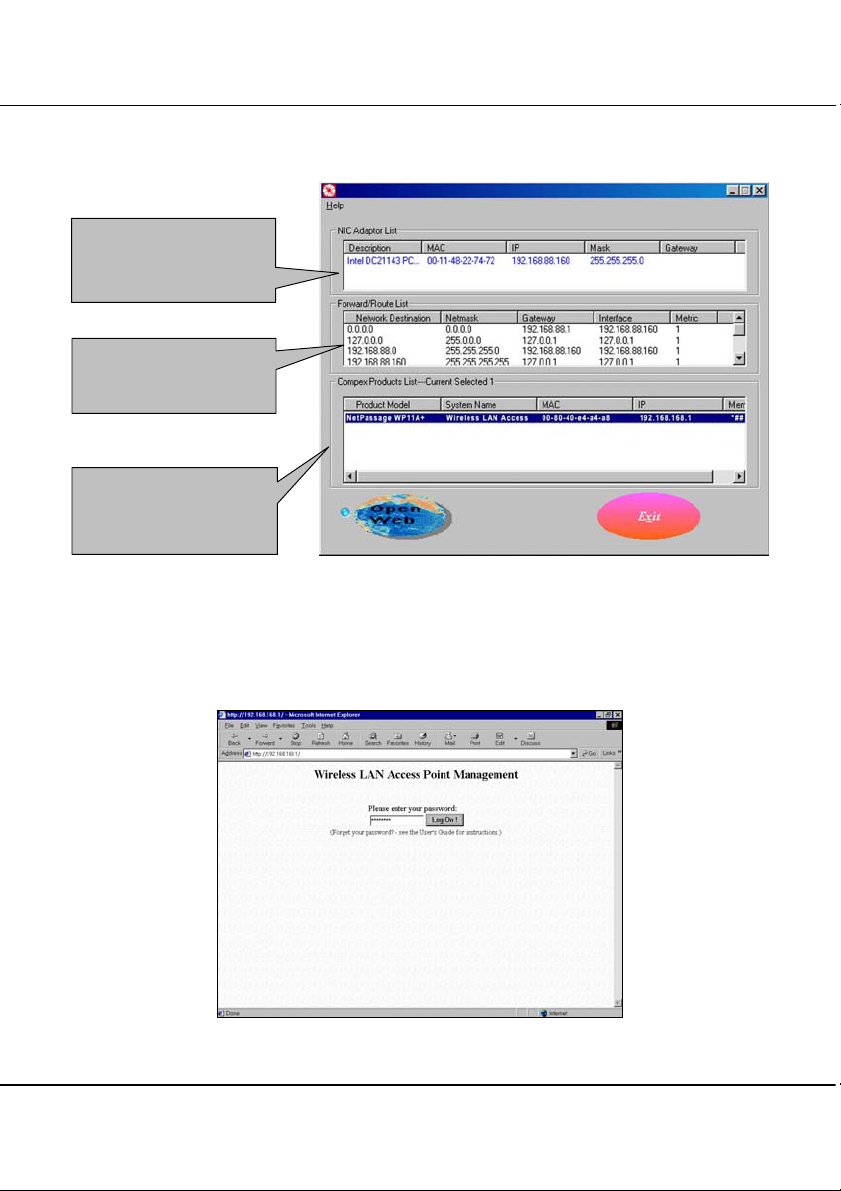
This will automatically launch the program and you will be greeted with the uConfig
application page as shown in Figure 4.1a.
This window lists all
Network Interface Card/s
installed in your system.
You can go through the
listing of all your N etwork
Card configuration.
This window indicates the
types of Compex product
which is installed in your
system.
Figure 4.1a Utility Configuration GUI
3. Click on the “OpenWeb” button and the system will automatically link you to
Compex WP11A+’s authentication page as shown in Figure 4.1b.
Figure 4.1b Log in to Compex WP11A+
13
Page 24
Chapter 4 Software Configuration
4. Click on the “Log ON!’ button to access the web based configuration interface of
the Compex WP11A+.
The default password for the login configuration interface is password. You will be able
to change the login password which will be elaborated in “Change Password” section
on Page 73.
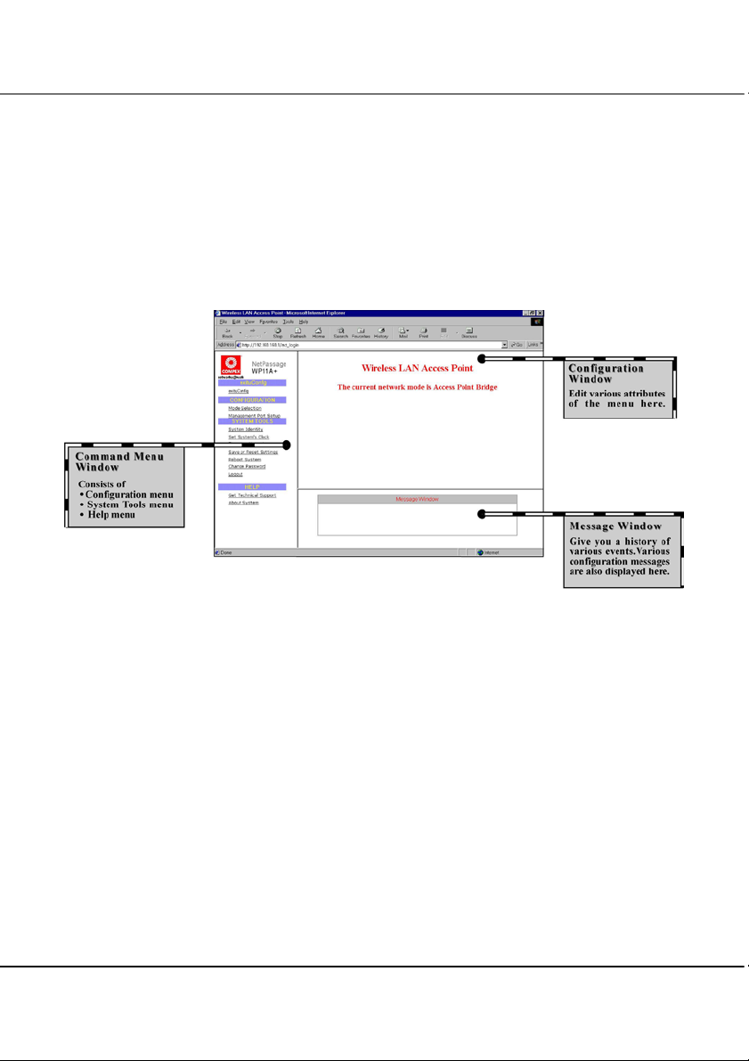
The main menu screen will be displayed as shown in Figure 4.1c.
Figure 4.1c Compex WP11A+ Configuration Interface
From here, you will able to see three different window frames on the screen, namely
Command Menu Window, Configuration Window and Message Window.
You will see a listing of the functions stated in the Command Menu Window. The
functions will vary according to the mode which you have selected. Different modes
will provide different functions in the Command Menu Window.
14
Page 25

Chapter 4 Software Configuration
4.1.1 AP Bridge and AP Client Mode
Exit uConfig Mode menu
• ExituConfig
CONFIGURATION menu
• Mode Selection
• Management Port Setup
SYSTEM TOOLS menu
• System Identity
• Set System’s Clock
• Firmware Update
• Save or Reset Settings
• Reboot System
• Change Password
• Logout
HELP menu
• Get Technical Support
• About System
• Gateway Mode
4.1.2 Gateway and Wireless Routing Client Mode
Exit uConfig Mode menu
• ExituConfig
CONFIGURATION menu
• Mode Selection
• uConfig IP Setup
• Management Port Setup
• WAN Setup
• NAT
• Static Address Translation
• Routing
• Filtering
• Remote Management
– Contact information of a technical support engineer
– End the Utility Configuration Program
– Basic Ethernet and Wireless setup
–Edit various internal settings of Compex WP11A+
SYSTEM TOOLS menu
• System Identity
• Set System’s Clock
• Firmware Update
• Save or Reset Settings
15
Page 26

Chapter 4 Software Configuration
• Reboot System
• Change Password
• Logout
HELP menu
• Get Technical Support
• About System
With this user-friendly web based configuration interface, all configurations on the
Compex WP11A+ can now easily be achieved, allowing you to configure your network
promptly.
16
Page 27

Chapter 5 Configure Compex WP11A Using Web Interface
Chapter 5 Configure Compex WP11A+ Using Web Interface
This chapter explains the Configuration Menu tool of Compex WP11A+ the web-based
configuration interface. To communicate with the network, DHCP Gateway IP Address should
be common to the AP Client. Settings for network parameters depend on the configuration of
your individual network.
Network Mask
Network Mask identifies the class of the Gateway’s
IP address. The users may configure the network
with Class A (255.0.0.0) and Class B (255.255.0.0)
Network Mask as well. In addition, Compex WP11A
can be configured for Classless Subnet to support
certain application.
DHCP Start/End IP Address
These parameters specify the range of the IP address
of which the DHCP Server will assign. For
example, if the DHCP Start IP Address and DHCP
End IP Address are 192.168.168.100 and
192.168.168.200 respectively, the first IP address
that the DHCP Server releases will be
192.168.168.100 while the last IP address that it
will release is 192.168.168.200.
DHCP Gateway IP Address
The DHCP S erver will automatically a ssigned a
Gateway IP Address when the PC is connected in
the same network.
Primary/Secondary DNS IP Address
Domain Name Service is an Internet service that
translates domain na mes into IP addresses. If your
WAN connection is using Static IP, you should
configure the primary and secondar y DNS IP
addresses with the DNS information provided by
your Broadband Internet Service Provider. For other
WAN connection types, the DNS IP addresses are
obtained automatically from ISP. The Always use
these DNS servers checkbox can be used to disable
the automatic process, and your preferred DNS IP
addresses can be used.
IP Address
IP address uniquely identifies the
Gateway in the network. whereby
the users should point their
Internet gateway to, if fixed IP
addresses are configured on the
computers in the network.
DHCP Server
Dynamic Host Configuration Protocol
Server dynamically assigns IP addresses to
the comput ers connected in t he same
network. If a computer has been configured
to dynamically obtain IP address, the DHCP
Server will release an available IP address
beginning from the DHCP Start IP Address
to the computer. If you have set the TCP/IP
protocol of your PC to dyna mic IP address,
the built-in DHCP server will assign the
DHCP Start IP Address and DHCP End
IP Address automatically to the PCs
connected in the same network. For dynamic
WAN IP, the DNS IP address is obtained
automatically from the ISP.
Figure 5.1a Management Port Setup Interface
17
Page 28
Chapter 5 Configure Compex WP11A Using Web Interface
5.1 Changing the IP Address of Compex WP11A+
You can also assign a specific IP address to the Compex WP11A+. To change the IP
address,
1. Enter the new IP address in IP Address entry.
2. Click “Save” button and reboot the device to update the configurations.
3. Logon again using your new IP Address to avoid connection with an incorrect
profile.
5.2 Configuring DHCP Server
You may configure the built-in DHCP Server of the Compex WP11A+ to release a
specific IP address to a specific computer via the web-based configuration interface.
You may also view the IP releases online.
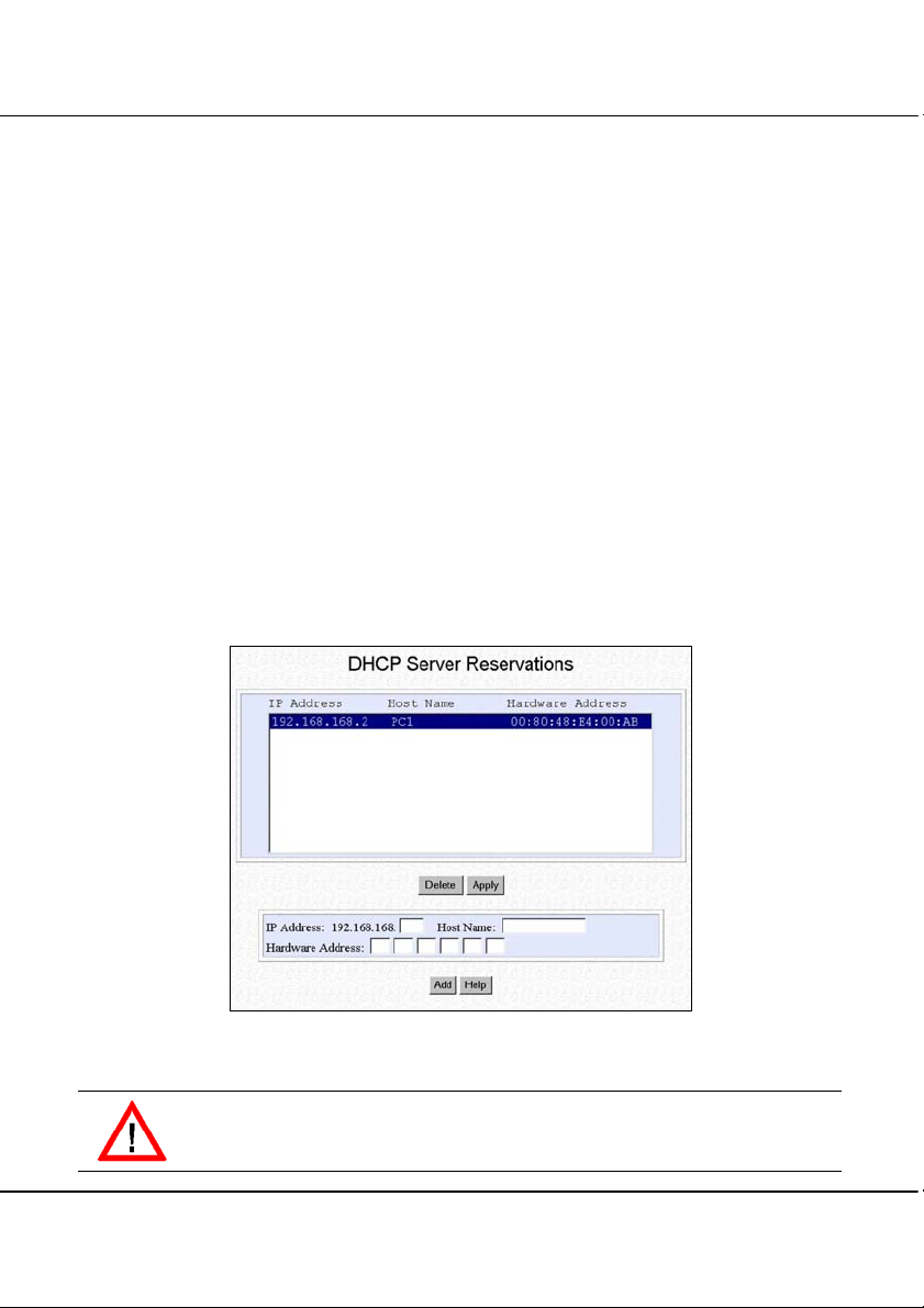
The DHCP Server can also be configured to reserve specific IP address for specific host
or Mac address.
Figure 5.2a DHCP Reservations of IP Address
CAUTION
The reserved IP address to be assigned should NOT have the same Dynamic IP
address range as the DHCP Start and End IP address.
18
Page 29
Chapter 5 Configure Compex WP11A Using Web Interface
To reserve a certain IP address for a specific workstation
1. Click on “DHCP Server Reservations” button in the Management Port Setup Menu.
2. Enter the specific IP address to be assigned to your designated PC.
3. Assign a name for the Host of the designated PC.
4. Fill in the MAC address of the designated PC in the Hardware Address entry.
NOTE
The DHCP server will ignore the Host Name if it finds a match in the Hardware
Address. It checks the Hardware Address first, so you need only to enter either
the Host Name or Hardware Address.
To add an entry
1. Click “Add” button to create an entry into the DHCP Server Reservations.
2. After the address is entered, click “Apply” button to make the updates effective.
You need to reboot and logon WP11A+ again to activate the changes.
NOTE
The reserved IP address must not be within the range of DHCP start and end IP
addresses.
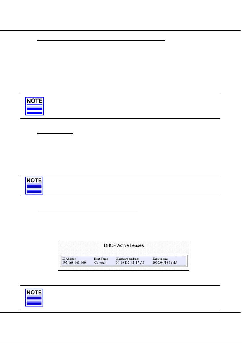
To view the IP released by the DHCP Server
1. Press the Show Active DHCP Leases button in the LAN Setup window shown in
Figure 5.1a. The list of released IP addresses will be displayed, as shown in Figure
5.2b.
Figure 5.2b Show DHCP Leases
NOTE
Invalid date and time shown under Expires column indicates that the router’s
clock of your Compex WP11A+ has not been set. Refer to “Set System Time”
on Page 69 to set the system’s clock.
19
Page 30

Chapter 5 Configure Compex WP11A Using Web Interface
5.3 Setting up Wireless Per Group Pseudo LAN using AP Bridge Mode
With more wireless networks being deployed in public premises, privacy protection
against unknown users has been an increasingly grave concern. The Wireless Pseudo
VLAN segregates each wireless client or group of wireless clients into its own Pseudo
VLAN. This restricts communication between wireless clients of different Pseudo
VLAN while retaining wireless accessibility to the network resources.
The subnet view illustrates Pseudo Group 1, Group 2 and Group 3 not only can surf the
Net freely, but they also can access the server easily. The PCs within its own group will
be able to communicate with one another. However, communications between Group 1,
Group 2 and Group 3 are not permissible.
Pseudo
Group 1
WEP1
Internet
& Fast
Ethernet
Pseudo
Group 2
WEP2
Pseudo
Group 3
Figure 5.3a Per Group Pseudo VLAN Subnet View
20
Page 31

Chapter 5 Configure Compex WP11A Using Web Interface
The physical setup of Per Group Pseudo VLAN is illustrated as shown.
Group 2
Group 1
WP11A+
Figure 5.3b Physical Setup for Wireless to Ethernet Bridging
Starting Point
The default mode for Compex WP11A+ is in AP Bridge, therefore no further
configuration is required.
1. Activate uConfig program. Click on “OpenWeb” button. You are now in the default
web page of Compex WP11A+.
Group 3
Internet
Switch/Hub
Server
Figure 5.3c Device in AP Bridge Mode
The device is in AP
Bridge Mode.
21
Page 32

Chapter 5 Configure Compex WP11A Using Web Interface
2. Click “Apply” button from the Network Mode Setup GUI and the web page for
Access Point Setup as shown in Figure 5.3d will appear.
Figure 5.3d Selection of Network Mode
3. Enter the Access Point Setup parameters for your network. An example is shown in
Figure 5.4e with these parameters entered.
Example:
Access Point Name: wlan
ESSID: Any
Channel: 3
TX Rate: Fully Auto
RTS Threshold: 2432
Frag Threshold: 2346
Pseudo VLAN: Disable
WEP encryption method: Disable
22
Page 33

Chapter 5 Configure Compex WP11A Using Web Interface
ESSID
This is an identifier that the devices use to
associate with the access point. It helps to
distinguish between multiple wireless
networks in the same vicinity.
Channel
The DSSS technology divides the 2.4GHz
band into 14 frequency channels. As
mentioned earlier, this is dependent on the
country’s regulation.
Tx Rate
When fully auto is selected, Compex
WP11A+ will automatically adjust the
transfer rate to the link strength. If the link
is weak, the transfer rate will be adjusted
from 11 to 5.5 to 2 to 1 Mbps. You can also
fix the transfer rate at 11, 5.5, 2 or 1 Mbps.
For fixed rate, once the transfer rate cannot
be reached, the link will be disconnected.
RTS Threshold
The RTS Threshold limits the length of the
RTS frame that is used to initiate a
transmission. Please do not change this field
unless you are familiar with IEEE 802.11
standard.
Frag Threshold
Fragment Threshol d limit s the maximum
frame to be transmitted. Please do not
change this field unless you are familiar
with IEEE 802.11 standard.
Access Point Name
If you have a few wireless access
points in your LAN, it will be good
that you give a name so that it will
be easier to identify the various
access points.
WEP Encryption Method
If the WEP encryption is
enabled, only devices with the
same encryption key can
communicate with each other.
Pseudo VLAN
Disabling the Pseudo VLAN allows the
wireless clients to have the capability to
communicate with one another, reducing
the privacy among users. However, if Per
Node (maximum 10 nodes) or Per Group
(maximum 4 groups) Pseudo VLAN is
activated, access to other wireless clients
is not permitted.
Figure 5.3e Access Point Setup Elaboration of Compex WP11A+
23
Page 34

Chapter 5 Configure Compex WP11A Using Web Interface
4. Select Per Group in the Pseudo VLAN pull-down menu as shown below and click
the “Apply” button.
Figure 5.3f Defining Access Control
5. Add in the MAC Address of those wireless clients into the various groups. For the
example illustrated in Figure 5.3b, you need to add in the MAC Addresses for the
three groups of wireless clients.
Figure 5.3g Defining Pseudo VLAN using MAC address
24
Page 35

Chapter 5 Configure Compex WP11A Using Web Interface
6. Click “Add” button. Choose your GroupID and key in the client’s MAC address as
shown below. Click on “Apply” button as shown in Figure 5.4h.
Figure 5.3h Adding MAC address
7. Next, you have the option to choose either 64-bits or 128-bits WEP Encryption.
Select your option and click the “Apply” button.
Figure 5.3i Selecting WEP encryption method
8. For 64-bit WEP encryption, you may enter 10 hexadecimals into the individual
Key.
Figure 5.3j Defining the key for 64-bit WEP
25
Page 36

Chapter 5 Configure Compex WP11A Using Web Interface
NOTE
You can store up to 4 Encryption keys in Compex WP11A+. However,
only one key can be used at anytime.
For 128-bit WEP encryption, enter your 26 hexadecimal encryption key and
click on the “Save” button. Reboot the device.
Figure 5.3k Defining the key for 128 bit WEP
9. Click on the “Save” button and then reboot Compex WP11A+ for the changes to
take effect.
To delete a client from the Pseudo Group
If you want to delete any of the unnecessary MAC Addresses,
1. Select the GroupID and click on the “Apply” button.
2. Highlight the MAC address of the client which you want to delete and click on the
“Delete” button.
Figure 5.3l Delete MAC Address of a client
26
Page 37

Chapter 5 Configure Compex WP11A Using Web Interface
You can also have a combination of encryption settings in each Pseudo VLAN setting.
The combinations can be summarized in the table below:
No. Pseudo VLAN WEP encryption method
1 Disable Disable
2 Disable 64 bit
3 Disable 128 bit
4 Per node Disable
5 Per node 64 bit
6 Per node 128 bit
7 Per group Disable
8 Per group 64 bit
9 Per group 128 bit
For combination settings, the methods to key in the fields are the same.
27
Page 38

Chapter 5 Configure Compex WP11A Using Web Interface
5.4 Setting up Wireless LAN-to-LAN Bridge Network using AP Client Mode
Compex WP11A+ may be configured as a wireless client, functioning in conjunction
with another IEEE 802.11b-compliant Access Point to perform transparent Bridging
between two Fast Ethernet networks.
The following physical layout of a Wireless LAN-to-LAN Bridge shows Compex
WP11A+ functioning as an ESS Client, performing Fast Ethernet LAN-to-LAN
Bridging by accessing an ESS Access Point.
Internet &
Wireless Bridge
Compex WP11A+
operating as an
AP Bridge
Compex WP11A+
operating as a
Client
Figure 5.4a Physical setup of Wireless LAN-to-LAN Bridge
28
Page 39

Chapter 5 Configure Compex WP11A Using Web Interface
Starting Point
With Compex WP11A+ in its default setting,
1. Activate uConfig program, click on the “OpenWeb” button.
2. Go to the CONFIGURATION menu and click on Mode Selection. In the Network
Mode Setup, select Access Point Client as shown in Figure 5.4b.
Figure 5.4b Selection of Network Mode
3. Click on the “Apply” button. The system will prompt you to reboot your system.
4. Go to uConfig program and wait for the system to refresh the screen. Click on the
“OpenWeb” button to proceed. The system will lead you to the authentication page
again. Logon again and Compex WP11A+ will be in AP Client Mode.
5. Go to “Mode Selection”. Click on the “Apply” button again. This time, the web
page for AP Client Setup will appear.
6. Enter the parameters as shown in Figure 5.5c.
29
Page 40

Chapter 5 Configure Compex WP11A Using Web Interface
State
3 kinds of status: Associated: BSS
Mac Address, Authentication or
Association failed and Not connected.
Channel
The Direct Spread Sequence Spectrum (DSSS)
technology divides the 2.4GHz band into 14
frequency channels, wher e the number of freelyse channels is subjected to the local regulations
of indivi dual country/region, na mely 14 channels
for Japan; 13 channels for European, except
France (ETSI); 11 channels for United States &
Canada (FCC) and 4 channels for France.
Tx Rate
There are 4 types of transmission
rate, namely, 1Mbps; 2Mbps;
5.5Mbps and 11Mbps.
Figure 5.4c Access Point Client Setup
7. Next, you have the option to choose either 64-bit or 128-bit for WEP Encryption
from the WEP Setup as shown below. Select your option and click on the “Apply”
button.
Figure 5.4d Selecting WEP encryption method
30
Page 41

Chapter 5 Configure Compex WP11A Using Web Interface
8. Enter your encryption key. The parameters take in hexadecimals.
Figure 5.4e Encryption entries for 64-bit
Figure 5.4f Encryption entries for 128-bit
9. Click on the “Save” button and then reboot to take effect.
31
Page 42

Chapter 6 Setting up Wide Area Network using Gateway Mode
Chapter 6 Setting up Wide Area Network using Gateway Mode
This chapter will elaborate on how the Compex WP11A+ can be set as a Broadband Internet
Gateway. As the Compex WP11A+ supports different types of broadband connections, it is
important that you choose the right connection type.
6.1 Selecting the Right connection for your Broadband Internet Service
The following summarizes the type of connection suitable for your broadband Internet
subscription.
Static IP
This type of connection should only be used if and only if you have subscribed to a
fixed IP address or a range of fixed IP addresses from your service provider for your
Internet connection.
Dynamic IP
This type of connection should be used if you are configuring the Compex WP11A+ for
your Internet service. Once powered on, the Compex WP11A+ will request for an IP
address, which will be automatically assigned by your service provider. Certain Internet
Service Providers require DHCP Client ID before an IP address is released. For such
cases, you must configure the System Identity with a System Name and this is
equivalent to the DHCP Client ID. The configuration of System Identity may be found
in the section on “System Identity” on Page 68.
PPP Over Ethernet (PPPoE)
This type of connection should be chosen for ADSL services in countries that use
standard PPP over Ethernet (PPPoE) for authentication. This includes Germany which
uses T-1 connection.
NOTE
If you are using SingTel Magix SuperSurf in Singapore, you should select
Singapore ADSL (Ethernet 512K). Subscribers of SingNet Broadband and
Pacific Internet Broadband should select PPPoE as their WAN types.
Australia BPA Cable
This type of connection is specially customized for BPA Cable Internet subscribers in
Australia.
NOTE
If you are using Big Pond Cable Internet in Australia, you should select
Australia BPA Cable as the WAN type for your Compex WP11A+.
32
Page 43

Chapter 6 Setting up Wide Area Network using Gateway Mode
NOTE
If you are subscribers of OPTUS in Australia, please select Dynamic IP as your
WAN type and configure the router’s System Name with the DHCP Client ID,
refer to section on System Identity of this User Manual on Page 68.
6.2 Setup on Compex WP11A+ for Broadband Internet Access
For such service, you should have the IP address provided by your ISP ready before
proceeding.
1. Connect a crossover cable from the Ethernet port of the Compex WP11A+ to your
workstation.
WP11A+
Workstation
Figure 6.2a Connect Compex WP11A+ to PC
2. As there are many different brands of broadband modems, some broadband modems
may provide a straight-connect (MDI) Ethernet cable while some may use a crossconnect (MDIX) Ethernet cable.
For example:
Aztech Turbo 900 provides cross-connect (MDIX) cable while Alcatel 1000 ADSL
modem provides straight-connect (MDI) cable.
3. Power on both your workstation and the Compex WP11A+. The WLAN LED
should light up, indicating the connection has been established.
4. You may start to configure the Compex WP11A+ before connecting to the Internet.
Please refer to “Configure Compex WP11A+ Using Web Interface” section on Page
17.
5. After configuration, switch off both your workstation and Compex WP11A+.
33
Page 44

Chapter 6 Setting up Wide Area Network using Gateway Mode
6. Next, remove cable from your workstation and insert it into your modem’s Ethernet
port.
Either PC or notebook
Cable/ADSL
Modem
WP11A+
Internet
xx
Figure 6.2b Connect Compex WP11A+ to modem
7. Power on your broadband modem and wait for it to complete the initialization
process which may take a minute or more.
8. Next, power ON the Compex WP11A+. When either of the 10M or 100M Ethernet
LED lights up, this shows that there is a cable connection between the ADSL
modem and the Compex WP11A+.
9. Power ON the PC/notebook and the WLAN port LED should light up after entering
the Windows environment. This indicates good cable connection between the PC
and the Compex WP11A+.
10. Once everything is checked, you can now access to the Internet.
34
Page 45

Chapter 6 Setting up Wide Area Network using Gateway Mode
6.3 Configure Compex WP11A+ using Web Interface
Notebook
Workstation 2
Workstation 1
Cable/ADSL
Modem
Figure 6.3a Physical layout for Wireless Broadband Internet Gateway
Assuming that Compex WP11A+ is in the default setting.
1. Activate the uConfig program, click on the “OpenWeb” button.
2. Go to the CONFIGURATION menu and click on Mode Selection. Select
Gateway mode and click on the “Apply” button. Next, click on the “Yes” button to
reboot the device.
WP11A
Internet
35
Page 46

Chapter 6 Setting up Wide Area Network using Gateway Mode
3. Go to uConfig program and click on the “OpenWeb” button. Logon again and now
Compex WP11A+ is in Gateway Mode.
Figure 6.3b Selection of Network Mode – Gateway
4. Next, click on the “Apply” button to proceed to the Access Point Setup.
Figure 6.3c Access Point Setup in Gateway Mode
36
Page 47

Chapter 6 Setting up Wide Area Network using Gateway Mode
5. For details in configuring Pseudo VLAN and WEP encryption method, please refer
to the “Setting up Wireless Per Group Pseudo LAN using AP Bridge Mode”
section, Step 4 on Page 20.
6. If you want to configure WAN setup, proceed to WAN Setup and the following
GUI will appear. By default, Compex WP11A+ is pre-configured with Dynamic IP,
which is suitable for most Cable Internet service providers.
Figure 6.3d WAN setup
Alternatively, you may also choose the different WAN type by clicking on the
“Change” button. For more details, please refer to the next chapter.
37
Page 48

Chapter 6 Setting up Wide Area Network using Gateway Mode
6.3.1 Advanced configuration in Gateway Mode
uConfig IP Setup
By selecting uConfig IP Setup function from the Command window, you can
change the IP address which the uConfig program will trace.
Figure 6.3e uConfig IP Setup
More advanced features can also be configured to Compex WP11A+ for you
to manage the LAN usage of Internet access better, such as installing the filter
rule. Details on how to create rules for filtering can be found in “Packet
Filtering” on Page 64.
38
Page 49

Chapter 7 Setting up WAN using Wireless Routing Client
Chapter 7 Setting up WAN using Wireless Routing Client
Setting Compex WP11A+ as a wireless routing client enables you to access to the internet
through wireless method. The PCMCIA LAN card will act as a WAN port. It will communicate
with an Access Point and then from there, we can access to Internet through the ADSL/Cable
modem which is connected to the Access Point. In this way, the Ethernet port of Compex
WP11A+ can be used to connect to other networking devices, such as switches to cater for more
PCs.
7.1 Setting up Compex WP11A+ as Wireless Routing Client
1. Connect a crossover cable from the Ethernet port of the Compex WP11A+ to your
workstation.
WP11A+
Workstation
Figure 7.1a Connect Compex WP11A+ to PC
2. Power on both your workstation and the Compex WP11A+. The WLAN LED
should light up, indicating the connection has been established.
3. You may start to configure the Compex WP11A+ before connecting to the Internet.
Please refer to “Configuring Compex WP11A+ as Wireless Routing Client
through Web Interface” on Page 41.
39
Page 50

Chapter 7 Setting up WAN using Wireless Routing Client
notebook
Two devices
communicate with one
another wirelessly
Cable/ADSL
Modem
Internet
WP11A+ acts
as a wireless
routing client
Figure 7.1b Physical layout for setting Compex WP11A+ as Wireless Routing Client
4. Power on the broadband modem and wait for it to complete the initialization process
which may take a minute or more, depending on the brand and design of individual
modem.
5. Next, power ON the Compex WP11A+ and Compex NP16. When either of the 10M
or 100M Ethernet LED lights up, this shows that there is a good cable connection
between the ADSL modem, Compex WP11A+ and Compex NP16.
6. Power ON the PC/notebook and the WLAN port LED should light up after entering
the Windows environment. This indicates good cable connection between the
switch/notebook and the Compex WP11A+.
7. Assume that Compex NP16 has been configured as an Access Point, you can now
access to the Internet.
NP16 acts as an
Access Point
40
Page 51

Chapter 7 Setting up WAN using Wireless Routing Client
7.2 Configuring Compex WP11A+ as Wireless Routing Client through Web
Interface
Assuming that Compex WP11A+ is in the default setting.
1. Activate the uConfig program, click on the “OpenWeb” button.
2. Go to the CONFIGURATION menu and click on Network Mode Selection.
Select Wireless Routing Client mode and click on the “Apply” button. Next, click
on the “Yes” button to reboot the device.
Figure 7.2a Selection of Network Mode – Wireless Routing Client
NOTE
Do not hit the “Logon” button. This will not lead you to the authentication
page!!
3. Go to uConfig program and click on the “OpenWeb” button. Logon again and now
Compex WP11A+ is in Wireless Routing Client Mode.
41
Page 52

Chapter 7 Setting up WAN using Wireless Routing Client
4. Next, click on the “Apply” button to proceed to the Wireless Routing Client Setup.
Tx Power
Tx Power indicates power transmit to
the wireless broadcast. The higher the
number (15db), the more powerful it is.
Signal Strength
Indicates the strength of the
signal. 100% will be in the full
strength.
Figure 7.2b Wireless Routing Client Setup
5. Next, you have the option to choose either 64-bit or 128-bit for WEP Encryption
from the WEP Setup as shown below. Select your option and click on the “Apply”
button.
Figure 7.2c Selecting WEP encryption method
42
Page 53

Chapter 7 Setting up WAN using Wireless Routing Client
6. Enter your encryption key. The parameters take in hexadecimals.
Figure 7.2d Encryption entries for 64-bit
Figure 7.2e Encryption entries for 128-bit
7. Click on the “Save” button and then reboot to take effect.
8. If you want to configure WAN setup, proceed to WAN Setup and the following
GUI will appear. By default, Compex WP11A+ is pre-configured with Dynamic IP,
which is suitable for most Cable Internet service providers.
43
Page 54

Chapter 8 Configuration on Various WAN Type
Chapter 8 Configuration on Various WAN Type
This section explains how to configure the Compex WP11A+ as a Wireless Broadband Internet
Gateway to distribute Broadband Internet Access to a wireless network.
Besides Dynamic IP connection, Compex WP11A+ also supports Static IP, PPP over Ethernet,
Singapore ADSL (Ethernet 512K) and Australia BPA Cable.
If you have chosen self-installation when you register for your broadband service, you should
first test the ADSL modem together with the logon account on your PC or notebook. Ensure that
it can connect successfully before attempting to run it with Compex WP11A+.
For simplicity and illustration purposes, it is assumed that the following LAN environment uses
the IP address 192.168.168.xxx and Compex WP11A+ is using the default settings.
However, if you have assigned a different IP address for Compex WP11A+, then use the new
settings in the setup procedures.
8.1 Configuring Static IP Connection
1. Go to WAN setting at Command Window, click on the “Change” button and check
the radio button next to the Static IP Address.
2. Click on “Save” button to update the data.
Figure 8.1a Select WAN Type - Static IP Address
44
Page 55

Chapter 8 Configuration on Various WAN Type
3. The WAN Setup screen shows a Static IP Configuration that allows you to
configure your Static IP connection to your ISP.
Figure 8.1b WAN Static IP Address Configuration
4. Fill in the required field for the IP address, Network Mask and Gateway.
5. All these information can be obtained from your ISP/Network Administrator.
6. After you have entered every field, click on the “Save” button to save the
configuration and reboot the Compex WP11A+.
Now you can surf the Internet freely.
45
Page 56

Chapter 8 Configuration on Various WAN Type
8.2 Configuring Dynamic IP Connection
The Compex WP11A+ is pre-configured with WAN connection using Dynamic IP.
Hence, if you are using Cable Internet access, you do not need to configure the WAN
connection.
However, if your account requires a DHCP Client ID in order to release an IP address,
you may need to configure the name of Compex WP11A+ with that of the DHCP Client
ID issued by your ISP.
See the section on “System Identity” on Page 68, and remember to enter the DHCP
Client ID issued by the ISP into the System Name field in the System Identity.
NOTE
If your computer is not able to resolve any web site, please verify that your
DNS entry of the computer has been defined correctly.
8.2.1 How to configure Singapore Cable Vision (SCV) Service
SCV provides a Dynamic IP address connection service. Assuming that your
WP11A+ is not in the Dynamic IP setting, please follow the procedures to
change to the appropriate WAN type.
1. Go to WAN Setup. Click on the “Change” button for list of other WAN
types Selection.
2. On the list of other WAN types selection, check the radio button next to
the Dynamic IP Address and click on the “Save” button.
Figure 8.2a Dynamic IP Address – for SCV broadband provider
Now, you can start surfing the Internet. You might want to manage the
Internet access by setting Filtering rules etc. For details, please refer to
“Packet Filtering” on Page 64.
46
Page 57

Chapter 8 Configuration on Various WAN Type
8.2.2 How to Configure @HOME Cable Service
Many broadband services require a simple DHCP request for connection. Two
such cable services are Optus@Home and Roger@Home.
To configure the @HOME Cable Service,
1. Follow the steps stated in the previous “Configuring for Singapore
Cable Vision (SCV) Service” section.
2. Next, click on System Identity at the Command window under the
SYSTEM TOOLS menu and enter the required field as shown.
System Name
You can obtain this information
from your ISP.
System Contact and Location
You may leave it as it is or fill in
your ISP contact and location
information. They are for your
future reference only.
Figure 8.2b System Identity
3. Click on the “Apply” button to set the System Identity.
4. Reboot your device.
5. Now, you can start surfing the Internet. If you want to have advanced
configuration on your device, please refer to the “Packet Filtering”
section on Page 64 or the “Configuring Network Address Translation”
section on Page 57.
47
Page 58

Chapter 8 Configuration on Various WAN Type
8.3 Configuring PPP over Ethernet Session (PPPoE)
For Broadband service providers such as Pacific Internet Broadband and SingNet
Broadband, you have to select the PPPoE WAN configuration. This includes users in
Germany who use T-1 connection.
NOTE
Certain ADSL Internet subscriptions require Service Name to be specified in
order to establish a PPPoE connection.
8.3.1 How to Configure SingNet, PacNet and QALA DSL Broadband
This procedure assumes you have a login account from SingNet, Pacific
Internet or QALA DSL broadband service, and also all the necessary hardware
installation is in place.
NOTE
If you have opted for self-installation when you register for the broadband
service, you should first test out the ADSL modem by logging in from your
PC. Make sure it can connect successfully before attempting to run it with the
Compex WP11A+
1. Click on the WAN Type option on the Command window. The default
Dynamic IP setup page will display.
2. Click on the “Change” button and check the radio button next to the PPP
over Ethernet.
3. Click on the “Save” button.
Figure 8.3a PPP Over Ethernet –WAN Type
48
Page 59

Chapter 8 Configuration on Various WAN Type
The WAN Setup screen below displays the PPPoE configuration that allows
you to configure your ADSL access.
Username
Enter your ADSL login username in
this field.
Password
Enter your ADSL login password in
this field.
Service Name
Certain ADSL Internet
subscriptions require t he user to
key in the service name. You may
do so in this field.
Non-Standard PPPoE Ethernet Type
If you are using a Non-Standard PPPoE
ADSL connection like that of Pacific
Internet Broadband using a 3COM
ADSL modem, you will need to check
the box next to Use non-standard
PPPoE Ethernet type. If you are unsure
about the PPPoE type, leave the box
unchecked.
Idle Timeout
Idle Timeout is the
duration of non-activity
at the WAN port for
disconnection.
Figure 8.3b WAN PPPoE Configuration
NOTE
Singapore users should follow the format below to enter their usernames:
Pacific Internet Broadband: username@pacific.net.sg
SingNet Broadband: username@singnet.com.sg
QALA DSL: username@qala.com.sg
4. After you have entered the required field, click on the “Save” button to
update the configuration. Reboot the Compex WP11A+.
Now, you may activate the Internet Explorer and start surfing the Internet.
Once the Compex WP11A+ is up and running, you might want to add
advanced configurations such as Filtering to better manage your LAN. For
details, refer to the “Packet Filtering” section on Page 64.
49
Page 60

Chapter 8 Configuration on Various WAN Type
8.4 Configuring for SingTel Magix SuperSurf
With your ADSL modem and PC, you can configure your WAN using the login account
from SingTel Magix broadband service.
1. Select WAN Type and click on the “Change” button.
2. Check the radio button next to the Singapore ADSL and click on the “Save” button.
Figure 8.4a WAN Type - Singapore ADSL
3. The WAN Setup screen displays the configuration for Singapore ADSL which
allows users in Singapore to configure their connection for Magix SuperSurf (512K)
ADSL Broadband Internet.
Figure 8.4b Singapore ADSL for SingTel Magix
50
Page 61

Chapter 8 Configuration on Various WAN Type
4. Enter Username, Password, Service Name (optional) and Idle Timeout (disabled
at default).
5. Click first the “Save” and then on the “Reboot” button to complete the WAN
configuration.
If all connections are properly established an Internet request, the Compex WP11A+
will detect and automatically establish the connection with Magix SuperSurf.
Next, activate the Netscape/Microsoft Internet Explorer browser to start surfing the
Net.
In addition, you can implement advanced features such as Filtering (“Packet
Filtering” on Page 64) to control over your LAN users’ Internet access.
8.5 Configuring for BigPond Australia (BPA)
This type of connection is specially customized for BPA Cable Internet subscribers in
Australia.
NOTE
For OPTUS subscribers in Australia, you have to select Dynamic IP as your
WAN type and configure the Compex WP11A+’s System Name with the
DHCP Client ID. Please refer to “Configuring Dynamic IP Connection”.
1. Click on WAN Setup and click on the “Change” to select WAN type as Australia
BPA Cable.
Figure 8.5a Australia BPA Cable –WAN Type
51
Page 62

Chapter 8 Configuration on Various WAN Type
2. Click on “Save” and the Australia BPA Cable WAN Setup screen will appear for
you to set the configuration.
Figure 8.5b Australia BigPond Cable
Australia BPA Cable configuration allows Australian users to configure the connection
for BigPond Cable Internet. If you have subscribed to Optus@Home in Australia, please
configure your connection profile using Dynamic IP.
3. Fill in the required fields for Username, Password and Idle Timeout.
4. After you have entered every field, click on the “Save” button to save the
configuration.
5. Reboot Compex WP11A+.
Now, you can start surfing the Internet. To configure the Compex WP11A+ with
advanced functions such as NAT, filtering please refer to the “Configuring Network
Address Translation” section on Page 57 and “Packet Filtering” section on Page 64.
52
Page 63

Chapter 8 Configuration on Various WAN Type
8.6 Point to Point Tunneling Protocol (PPTP)
PPTP enables implementation of secure, multi-protocol Virtual Private Networks
(VPNs) through public data networks, such as Internet.
1. Click on WAN Setup and click on the “Change” to select WAN type as PPTP.
2. Press the Change button and the list of supported WAN type will be displayed as
shown below.
Figure 8.6a WAN Type – PPTP
53
Page 64

Chapter 8 Configuration on Various WAN Type
3. Check the PPTP radio button and press the Save button. The configuration page for
PPTP will be displayed.
Figure 8.6b Configuration on PPTP
4. Fill in the parameters for your PPTP service:
Connect IP
Username
Password
VPN Server
Idle Timeout
Key in the IP Address of your Service Provider.
Enter the username of your PPTP subscription.
Enter the password of the username.
Enter the IP Address for VPN server.
This field allows you to specify the idling timeout value for
Compex WP11A+ to disconnect from the ISP. “0” value in this
field disables idling timeout function. When set to “0”, Compex
WP11A+ remains connected unless disconnected by the ISP.
Once disconnected, Compex WP11A+ will stay offline until the
next Internet request is detected in the network.
54
Page 65

Chapter 8 Configuration on Various WAN Type
5. Press the Save button followed by the Reboot button to complete the configuration
process.
6. Enter all necessary information in the individual fields and press the Save button.
7. Press the Reboot button to complete the configuration process.
8.7 JTB BruNet e-Speed
JTB BruNet e-Speed is one of the ADSL technology which delivers high speed data
communication to home or business without interfering normal telephone service. Espeed will connect BruNet users at a higher speed of 128 kbps, 256 kbps, 384 kbps or
even 512 kbps, depending on the availability of the bandwidth to the web site being
access.
1. Click on WAN Setup and click on the “Change” to select WAN type as JTB
BruNet e-Speed (Brunei).
2. Press the Change button and the list of supported WAN type will be displayed as
shown below.
Figure 8.7a WAN Type – JTB Brunei e-Speed
55
Page 66

Chapter 8 Configuration on Various WAN Type
3. Check the JTB BruNet e-Speed (Brunei) radio button and press the Save button.
The configuration page for e-Speed will be displayed as follows.
E-Speed serves both business and residential customers.
Figure 8.7b Types of Service for JTB BruNet e-Speed
4. Select the type of services by clicking on the radio button.
5. Hit on the Save button and you can now surf the net comfortably.
56
Page 67

Chapter 9 Configuring Network Address Translation
Chapter 9 Configuring Network Address Translation
In this chapter, we will illustrate on how you can host some Internet Servers on your LAN via
the use of Compex WP11A+ configuration interface.
Before you attempt any NAT or Filtering configurations, you should ensure the Compex
WP11A+ is ready for basic Internet access on LAN.
9.1 NAT and Virtual Server
Compex WP11A+ comes with a simple Network Address Translation (NAT) Firewall
protection for your LAN. It uses a mechanism that substitutes a Private IP address with
a Public IP address when a packet leaves the Private network; and restore the
destination Public IP address with the Private IP address when the packet enters the
Private network. With NAT firewall, you can protect your LAN from unauthorized
access from the WAN.
One feature of the NAT is that any unauthorized requests from the Internet will not be
allowed to pass through Compex WP11A+. Hence, with NAT, you can host a Virtual
Server on the LAN. NAT works by translating packets of Private IP addresses to appear
as originating from a single Public IP address; thus allowing multiple PCs in the LAN to
appear as one PC to the WAN interface.
The implementation of a Virtual Server allows Internet servers such as Web Server,
FTP Server and Mail Server to be hosted on your network. It is able to support both Port
Forwarding and IP-Forwarding Servers.
NOTE
Note that static IP supports IP Forwarding only.
57
Page 68

Chapter 9 Configuring Network Address Translation
9.2 Defining Port-Forwarding Virtual Server
Port Forwarding redirects any incoming Public IP Internet request to another computer
on a Private IP based on its TCP/UDP Port number.
Hence, when a WAN user sends a request to your network, the Compex WP11A+
(based on the Port–Forwarding configurations) will forward these requests to the
assigned PC.
9.2.1 When to use Port–Forwarding Virtual Server
When your ISP assign you with only one fixed Public IP address, and you
want to define the various servers (such as, FTP, HTTP, Netmeeting, Mail
server etc ) to specific Private IP address in your LAN; you can choose to host
the servers by using the port-Forwarding Virtual server.
For example, suppose that you have a FTP Server with an IP address of
192.168.168.41 and your broadband ISP has assigned a Public IP address of
203.120.12.100 to the gateway. To support a Web Server in your Private
Network, you need to define an NAT Static Port-based Entry to forward
TCP port 21 (used by FTP) to 192.168.168.41. Every http://203.120.12.100
requests will then be forwarded to the FTP Server.
9.3 Configuring Port–Forwarding virtual server with Compex WP11A+
Follow the steps shown below to configure the Port Forwarding function.
1. Go to NAT function at the Command Window. Select Enable for the status.
Figure 9.3a Configuring Network Address Translation
58
Page 69

Chapter 9 Configuring Network Address Translation
2. Click on the “Port Forwarding” button to display the NAT Static Port Based
Entries GUI.
Figure 9.3b NAT Static Port Based Entries
3. Click on the “Add” button.
Known Server
It supports a pr e-defined list of
common Internet applications. You
do not have to know which
TCP/UDP port a specific Internet
application is assigned to the virtual
server.
Custom Server
It enables the user to define the
TCP/UDP port number for the
Virtual Server (of which is not
supported by the Known Server)
Figure 9.3c Add in new Port Based Entry
4. Enter the information, for example:
Private IP Address:192.168.168.14
Server Type: HTTP
5. Click on the “Add” button to add the address into the Port-based mapping table.
59
Page 70

Chapter 9 Configuring Network Address Translation
If you require assigning more PCs in your LAN as servers, use the “Add” button to
define the port-forwarding virtual server.
To utilize NAT, you have to enter the Private IP Address of the Virtual Server and the
Server Type (e.g. HTTP).
For those Internet applications not defined in the Known Server, you will have to enter
Port in the Custom Server (the port number for TCP/UDP port used by this Virtual
Server). You can also assign a name to this Virtual Server in the Server Type field.
Choose a Protocol for this Virtual Server ports. (e.g. TCP or UDP).
By clicking on the “Add” button at the Add New Port Based Entry, you have added a
new Virtual port.
If you wish to delete any of the entry, just select that particular entry and hit the
“Delete” key on the keyboard.
9.4 Configuring IP-Forwarding virtual server with Compex WP11A+
1. Click NAT at the Command window.
2. Select Enable NAT. Click “Apply” button and then click “Static IP Address
Entries” button.
Figure 9.4a IP Forwarding Option
60
Page 71

Chapter 9 Configuring Network Address Translation
3. Click on “IP Forwarding” button.
Figure 9.4b Adding New NAT IP address Entry
Enter the information in the respective parameter fields, for example:
Private IP Address: 192.168.168.40
Public IP Address: 203.100.10.99
4. Click add button to add the address into the IP address-mapping table.
Please note that you must enable the NAT function in the Configuration window if
you are using a single IP address account (fixed static IP) and want to share this
connection on your LAN.
By default, NAT status is set to Enable. Disabling NAT function is to be set only
when you want to a block public IP address from ISP.
To disable NAT, select Disable and press Apply.
61
Page 72

Chapter 10 Routing
Chapter 10 Routing
10.1 Configuring Routing Protocol
You can configure Compex WP11A+ to either Dynamic or Static Routing Protocol.
In dynamic routing, RIP1 and RIP2 will be chosen when there are multiple routes on
your network. The broadband Internet Gateway will keep on updating its IP routing
table with the latest routing information by automatically adjusting to any physical
changes in the network connection.
The routing table contains the network path and status information, which is used for
forwarding the information. The Routing Information Protocol (RIP) will receive the
routing information from other routers on the network.
10.2 Adding Static Routes
If you already have existing multiple routers in your network and have multiple kinds of
networks in your LAN, you may need to set up a static route between them to avoid the
hassle of reconfigurating to the network. In this way, you can also have better control
over the routes of your Compex WP11A+. For such cases, you can add a Static Routing
to the router.
1. Click on Routing. Click on the “Add” button to add the Static Route in the IP
Routing Table configuration shown.
Figure 10.2a IP Routing Table
62
Page 73

Chapter 10 Routing
You will set the desired Destination IP Address and the Gateway IP Address.
2. Click “Apply” button to save your changes. You need to save and reboot your
gateway.
Destination IP Address
A remote network IP address to
which you want to assign the static
route. For example, if you want to
route your WP11A to your entire
LAN, you may enter the IP
address as 192.168.168.0.
Gateway IP
The IP address that provides the
gateway between Compex WP11A
and the remote network.
Figure 10.2b Adding Static IP Routing
63
Page 74

Chapter 11 Packet Filtering
Chapter 11 Packet Filtering
11.1 Filtering
Compex WP11A+ allows Packet Filtering rules to be defined based on three factors,
Source IP Address, TCP Port and Time. IP Packet Filtering examines the outgoing
packets and decides whether to bypass or to block them. After the Packet Filtering rules
have been defined, the users may select to bypass or to block the outgoing packets that
do not match the rules.
Select on this
radio button
Figure 11.1a Adding Filtering Configuration
For example, assume that a rule has been defined as "TCP Port 23 (used by TELNET)
from any IP on any day at any time". If the “sent” radio button is selected, all outgoing
packets will be sent except TELNET session. If the discarded radio button is selected,
all outgoing packets will be blocked except TELNET session.
Click on Filtering function at the Command window.
64
Page 75

Chapter 11 Packet Filtering
To add a new rule
1. Press “Add” button.
The screen facilitates the users to add rules for IP Packet Filtering.
IP Address
Three values are possible for this field:
Any, Range or Single. If you have
selected Any, you may leave the next
two fields blank. If you have selected
Range, enter the range of IP addresses
in (From) and (To) fields. If you have
selected Single, you only need to enter
the specific source IP address in the
(From) field
Destination Port
Three values are possible for this field,
Any, Range or Single. If you have
selected Any, you may leave the next
two fields blank. If you have selected
Range, enter the range of TCP port in
(From) and (To) fields. If you have
selected Single, you only need to enter
the specific TCP port in the (From)
field.
Day of the Week
Two valu es are possible for this field,
Any or Range. If you have selected
Any, you may leave the next two
fields bla nk. If you have selected
Range, enter the duration of the
weekdays in (From) and (To) fields.
Time of the Day
Two values are possible for this field,
Any or Range. If you have selected
Any, you may leave the next two fields
blank. If you have selected Range,
enter the time in (From) and (To)
fields.
Figure 11.1b IP Filtering Configuration
2. Enter the appropriate data in the respective entries for Rule Name, IP Address,
Destination Port, Day of the Week and Time of the Day.
3. Press the “Apply” button to add the new rule or “Cancel” button to discard the rule.
4. To save the rules, click the Save or Reset Settings at the Command window under
the SYSTEM TOOLS Menu.
65
Page 76

Chapter 11 Packet Filtering
To delete a rule
1. Select the required rule on the Select to Edit column.
2. Click on Delete to activate the action.
To edit a rule
1. Select the required rule on the Select to Edit column.
2. Click on “Edit” button to activate the action,
3. Click “Apply” button to accept the rule or “cancel” button to discard the rule.
4. To save the rules, click the Save or Reset Settings at the Command window on
SYSTEM TOOLS menu.
CAUTION
You must synchronize the clock of Compex WP11A+ to your PC’s time for the
rules to execute accurately.
Refer to “Set System Time” on Page 69 to utilize the timing based function of
Compex WP11A+.
66
Page 77

Chapter 12 Remote Management
Chapter 12 Remote Management
12.1 Remote Management
The Remote Management feature is a useful function for those people who work from
home or sales personnel who are mostly away from the office. As long you have
Internet access at your Remote site, you can still manage your network.
To enable remote management,
1. Select Remote management at the Command window.
2. Enter the information, for example:
HTTP Port: 80
TELENET Port: 23
Figure 12.1a Remote management
3. Click on the “Save” and reboot the Compex WP11A+.
67
Page 78

Chapter 13 Using SYSTEM TOOLS menu
Chapter 13 Using SYSTEM TOOLS menu
13.1 System Identity
If you have multiple Compex WP11A+s in your network, it will be useful if you define
the respective Compex WP11A+ identities for ease of identification.
In some cases, your ISP may require you to define a System Name before you can
access the Internet. The System Name is also used as a DHCP Client ID in negotiation
with a DHCP Server for IP release. All these can be defined in the System Identity.
System Name
This parameter is used as a DHCP Client ID in
negotiation with a DHCP Server for IP leased. Certain
Cable ISPs, such as Optus@Home in Australia and
Excite@H ome in the United Stat es, require DHCP
Client ID to be authenticated first before leasing out an
Figure 13.1a System Identity Description
To do so,
1. Go to System Identity at the Command window.
2. Description on the System Name, System Contact (You may enter the contact
person for the Gateway in this field) and System Location (If there are multiple
Gateways in the network or building, you may enter a location to identify the
Gateway.)
3. Press “Apply” button to effect the changes.
68
Page 79

Chapter 13 Using SYSTEM TOOLS menu
13.2 Set System Time
It is recommended that you configure the Compex WP11A+’s timer to synchronize with
your PC so that you can utilize the time-based functions.
NOTE
To manage and utilize the time-based functions provided in the Compex
WP11A+, (such as the Filtering functions), you MUST set its clock to
synchronize with your managing workstation.
1. Access the SYSTEM TOOLS menu and click on the Set System’s Clock.
2. Select the appropriate time zone from the pull down menu. Next, click on the
“Apply” button.
Figure 13.2a Synchronizing Compex WP11A+’s timer
69
Page 80

Chapter 13 Using SYSTEM TOOLS menu
13.3 Firmware Upgrade
You can download the new Firmware upgrade from http://www.compex.com.sg for the
latest firmware revision. Here, you can download all future release of updated Firmware
by simply clicking on the links..
Figure 13.3a To upgrade Firmware
To perform the upgrade,
1. Click on Firmware Upgrade.
2. Click on the “Browse” button to locate the filename. Next, click on the “Upgrade”
button to begin the upgrading to the latest firmware revision.
Follow through the instructions during the upgrading process. Once completed,
remember to reboot Compex WP11A+ and login again to proceed with any
configurations.
NOTE
The firmware image file that you install from the CD-ROM may not be the
latest version. To get the most updated version, please go to
www.compex.com.sg to download the firmware.
To check your current firmware revision, click on the About System in the
HELP menu
.
70
Page 81

Chapter 13 Using SYSTEM TOOLS menu
13.4 Save or Reset Settings
This function allows the users to perform tasks on the configuration settings. You may
save the configuration that you have made to the Compex WP11A+, backup the
configuration on a file, restore the configuration from a file and reset the configuration
back to factory default.
The Save and Reset Settings allows you to execute the changes or reset the Compex
WP11A+ back to the default configuration.
Figure 13.4a Save and Reset Settings options
To Save
1. Click on the “Save” button to update all changes you have made previously.
2. Reboot Compex WP11A+ to ensure that it points to the right profile and logon
again.
71
Page 82

Chapter 13 Using SYSTEM TOOLS menu
To Backup
To backup Compex WP11A+’s configuration into a file, click on the “Backup” button.
To Restore
Click on the “Restore” button to restore the old configuration from your backup file.
To Clear and Reset your setting
By clicking on this button, you will restore Compex WP11A+ back to the default
settings. This includes disabling the DHCP Server. You will have to re-enter all the
configuration information for your network.
13.5 Reboot System
You can reboot the device by clicking on the Reboot System menu. Most of the
changes require you to reboot your Compex WP11A+ in order for the new settings to
take effect.
Click “Reboot System” button and then the “Yes” button.
Figure 13.5a Reboot System
72
Page 83

Chapter 13 Using SYSTEM TOOLS menu
13.6 Change Password
This option allows the System Administrator to amend the current password. The
default password is password. This password is being used for the web-based
configuration interface as well as in the Telnet session.
NOTE
Administrative password is case sensitive and only ONE password is Needed
for all the interfaces.
Figure 13.6a Changing of Password
1. Click on Change Password at the Command window and key in the entries
accordingly.
2. Click on the “Change Password” button to confirm changes.
3. Then click on the “Save & Reboot” button to activate the changes.
If you forget your password, simply reset Compex WP11A+. The password will reset
back to default, which is password. Please note that upon resetting the device, all
configurations will be back at the default settings.
73
Page 84

Chapter 13 Using SYSTEM TOOLS menu
13.7 Logout
With the web browser, logging out has never been easier. Simply click on the “Logout”
button and you will exit the web-based environment. The system will prompt you to log
in again as shown in Figure 13.7a. If you need access to the Compex WP11A+
Configuration again, please activate uConfig program again, regardless which mode
you may have previously worked in.
Figure 13.7a System prompt to log in again
NOTE
Do not use the Logon button, use uConfig program instead, to prevent any
conflict in IP Address.
13.8 Exit uConfig
Upon completion of the Compex WP11A+ configuration, go to Command window and
select Exit uConfig function. This will close the uConfig program. Notice the icon
located at the taskbar (bottom of your screen) has vanished! This shows that you have
successfully exited from uConfig program.
NOTE
If you need to configure Compex WP11A+ again, it is strongly recommended
you activate the uConfig program to access the web-based interface to reduce
any complication.
74
Page 85

Chapter 13 Using SYSTEM TOOLS menu
Figure 13.8a uConfig icon at the taskbar
uConfig icon will
disappear after
clicking on the
exituConfig bar.
75
Page 86

Chapter 14 Using HELP menu
Chapter 14 Using HELP menu
14.1 Get Technical Help
For more information on Compex’s technical support around the world, click on the Get
Technical Support in the HELP Menu.
Figure 14.1a Technical Support Information
76
Page 87

Chapter 14 Using HELP menu
14.2 About System
You can check the various configuration of the Compex WP11A+ by clicking on the
About System menu. After you have upgraded your firmware in the Compex WP11A+,
you can check for the version.
14.2.1 AP Bridge/AP Client Mode
Figure 14.2a Bridge/Client Mode System Information
14.2.2 Gateway Mode
Figure 14.2b System Information
77
Page 88

Chapter 15 Hardware Reset of Compex WP11A
Chapter 15 Hardware Reset of Compex WP11A+
The Compex WP11A+ is designed with a reset button located at the back of the cover. This
facilitates the resetting of the Compex WP11A+ to factory default settings, or to switch between
the work modes of Compex WP11A+. The reset push button functions in the three ways:
Functions of reset button Procedures
Recycle Power (Reboot) Hold and immediately release the reset button. The
DIAG LED will blink once and then lighted up for a
while.
Set to factory default Hold the reset button until the DIAG LED flashes at the
rate of 1 flash/sec. Release the button and the DIAG
LED will light up shortly. The AP Mode LED will then
light up steadily, indicates that Compex WP11A+ has
set to its factory default setting as shown below:
• Operating Mode: AP Bridge mode
• IP address: 192.168.168.1
• Password: password
• DHCP Server mode: Disabled
Toggling between the
operating modes
Hold the reset button until the DIAG LED blinks at the
rate of 2 flashes/sec. Release the button and Compex
WP11A+ will start toggling between the following
operating modes:
If you are in Access Point Bridge mode, the
WP11A+ will change to Gateway mode. The AP
Mode LED will be turned off and the DHCP server
mode will be enabled.
If you are in Gateway/Wireless Routing Client
mode, the device will switch to Access Point
Bridge mode. The AP Mode LED will be turned on
and the DHCP server mode will be disabled.
If you are in Access Point Client mode, the device
will be switched back to Access Point Bridge
mode.
78
Page 89

Appendix I Login to Web-based Interface manually
Appendix I Login to Web-based Interface manually
AI-1 Configuration of Compex WP11A+ using Web-based Interface
Another method of logging to web-based interface is to key in the IP Address manually.
This is quite tedious as the default IP Address for AP Bridge/Client Mode is different
from Gateway You need to configure your PC’s IP Address whenever you switch the
working mode. The IP Address of your PC must be configured as the same subnet as
Compex WP11A+.
To install a browser on the PC or workstation, make sure that TCP/IP protocol is
installed and configured. Configuration will be much simpler. If you decided to obtain
the IP address dynamically and use default IP addresses. Compex WP11A+ comes with
a built-in DHCP server that automatically assigns IP addresses, DNS and Gateway
information to the computers connected in the same network. It has been pre-configured
with IP address and Subnet Mask of 192.168.168.1 (for AP Bridge and AP Client mode)
and 255.255.255.0 respectively.
An Internet browser can be used to configure the Compex WP11A+. The most
commonly used browsers include the latest Netscape Navigator, Netscape
Communicator and Microsoft Internet Explorer browsers as they support frames and
Java. We recommend you use Netscape Communicator V4.06 and higher, or Microsoft
Internet Explorer 4.0 and higher.
Assuming that Compex WP11A+ is in its default setting, which is in the AP Bridge
mode, start running your browser on a workstation connected onto the same network as
the Compex WP11A+ by entering the URL address, http://192.168.168.1.
Login to Web Browser Interface
The following is a list of the various ways for different browsers to access a website.
Follow the instructions for the browser that you use.
In Netscape Navigator
1. Select the File menu, then select Open Location.
2. In the Open Location dialog box, key in the IP address of the Compex WP11A+.
This address is set at the factory to: http://192.168.168.1.
3. Click on the “Open” button.
79
Page 90

Appendix I Login to Web-based Interface manually
In Netscape Communicator
1. Select the File menu, and then click on the Open Page.
2. In the Open Page dialog box, key in the IP address of the Compex WP11A+. This
address is set at the factory to: http://192.168.168.1.
3. Make sure the Navigator radio button is selected. Then click the “Open” button.
In Internet Explorer
1. Select the File menu, then select Open.
2. In the Open Page dialog box, key in the IP address of the Compex WP11A+. This
address is set at the factory to: http://192.168.168.1.
3. Click on the “OK” button.
The following screen is displayed next in the Web browser program (Figure A1-1):
4. Type in the password and click on the “Log On!”. The default password is
“password”.
A1-1 Login to Wireless LAN Access Point Management
Now you can start configuring Compex WP11A+.
80
Page 91

Appendix II TCP/IP Configuration
Appendix II TCP/IP Configuration
This section discusses the configuration of your TCP/IP connection of your Compex WP11A+.
Upon the successful installation of the Compex WP11A+, the network adapter will be added to
your network folder. To configure your TCP/IP connection for Compex WP11A+, please follow
the steps listed below. If you are using Windows 2000/XP, please go to section AII-2
AII-1 Adding TCP/IP network protocol for Windows 98/98SE/ME
1. From the Windows 98/98SE/ME, go to Start, select Settings, and then Control
Panel.
2. Double-click on the Network icon and a Network screen will appear as shown:
Figure AII-1 Network Configuration
81
Page 92

Appendix II TCP/IP Configuration
3. Check your list of Network Components in the Network window Configuration
tab. If TCP/IP is not installed, click on the “Add” button to start the installation.
4. Select Protocol and click on the “Add “button.
Figure A11-2 Select Network Component Type
5. Select Microsoft and TCP/IP in Manufacturers and Network Protocols columns
respectively. Click on the “OK” button.
Figure AII-3 Select Network Protocol
82
Page 93

Appendix II TCP/IP Configuration
6. After TCP/IP is installed, go back to the Network screen and select TCP/IP in
the list of Network Components.
7. Click on the “Properties’ button, and configure the settings in each of the
TCP/IP Properties window.
Figure AII-4 Select TCP/IP protocol Figure AII-5 IP Address Configuration
NOTE
Please check with your system administrator or Internet Service Provider for
more information on the TCP/IP parameters.
83
Page 94

Appendix II TCP/IP Configuration
AII-2 TCP/IP network protocol configuration for Windows XP/2000
For Windows XP/2000 users, you do not need to install the TCP/IP protocol as it is
already installed when you first install a network card. As such, only the
configuration for TCP/IP is shown.
1. From the Start menu - click Control Panel, then click Network and Internet
Connections. Then click Network Connections and your computer screen will
change to a similar figure shown below.
Figure AII-6 Network Connections
2. Right click the network connections you want to edit and click on the
“Properties” button.
Figure AII-7 Compex WP11A+ Network Connection
84
Page 95

Appendix II TCP/IP Configuration
3. Select the Internet Protocol (TCP/IP) item and click on the “Properties” button.
Figure AII-8 IP Address Configuration
4. Configure your IP address and the rest of the parameters so that you can connect
to the network.
NOTE
Please check with your system administrator or Internet Service Provider for
more information on the TCP/IP parameters.
85
Page 96

Appendix III Configuration and Commands on Telnet Interface
Appendix III Configuration and Commands on Telnet Interface
AIII-1 Telnet Interface Configuration
This feature connects the Compex WP11A+ Gateway Local LAN port to your
network. You can directly connect your PC to Gateway Local LAN port, or
Gateway to any hub/switch on your network.
From any PC on your network, type “Telnet 192.168.168.1”. The IP address
“192.168.168.1” is the default IP address. If your network is using other IP address
other than default IP address, please change the IP address in the above command.
You will see a prompt asking you for the password. Type in the password which by
default is password. The password is case-sensitive and it is the same as the one in
the Web browser interface.
Now you should see the following command prompt “Command>”
Figure AIII-1 Telnet Environment
The Telnet Interface Command is the same as Command Line Interface. We
suggest using the Help command at the command prompt to guide you through
these commands.
86
Page 97

Appendix III Configuration and Commands on Telnet Interface
AIII-2 Command Line Interface Commands List
Command Examples
ping <d.d.d.d>
show ip
show ip stat
show ip routing table
show arp table
show icmp stat
show udp stat
87
Page 98

Appendix III Configuration and Commands on Telnet Interface
Command Examples
show tcp stat
show ethernet address
show gateway
set gateway <d.d.d.d
There are also some other commands such as:
set ip private <d.d.d.d> <d.d.d.d>
set ip lan <d.d.d.d> <d.d.d.d>
add ip routing <d.d.d.d> <d.d.d.d>
delete ip routing <d.d.d.d> <d.d.d.d>
AIII-3 How to recover Compex WP11A+ from failed firmware
This procedure details the upgrading of firmware to Compex WP11A+.
Compex WP11A+ will automatically switch to loader mode if the main code is
corrupted. Code can be corrupted due to power surges or it could be uploading
newer firmware results in router failing to startup.
1. Disconnect Compex WP11A+ from the network.
2. Connect one end of a MDIX cross-connect (MDIX) Ethernet cable on the WAN
port of Compex WP11A+ and the other end to your PC/notebook LAN adapter.
3. Power ON the device and the PC/notebook. You will notice that the DIAG LED
blinking rapidly. This indicates that the loader mode has discovered firmware
error and is awaiting uploading.
4. Insert the Product CD to your CD-ROM Drive.
88
Page 99

Appendix III Configuration and Commands on Telnet Interface
5. Go to Recovery folder and activate wp11arcv.bat.
The system will go to DOS Prompt automatically. Press any key to restore the
firmware. It will run the command from the batch file: TFTP -i 192.168.168.1
PUT Wp11a286.img as shown below.
Figure AIII-2 DOS Prompt Environment
When done, the system will prompt you a message “Transfer successful:
505807 bytes in 1 seconds, 505887 bytes/s”.
When the firmware image file is uploaded, it will copy it to the flashrom.
During uploading the firmware image file to Compex WP11A+, the DIAG LED
will light up.
NOTE
The firmware image file, which you upload from the CD-ROM may not be the
latest version. To get the most updated version, please go to
www.compex.com.sg to download the firmware. Do not power down the device
as data is being transferred.
Please note that your firmware image file might be different. Please enter the
name of that image file.
Please ensure that there is constant power supply to Compex WP11A+ while
performing the recovery process.
89
Page 100

Appendix III Configuration and Commands on Telnet Interface
Wait until the DIAG LED starts blinking slowly which may takes about 10
seconds. This indicates that the firmware has been loaded successfully. Power
off and on to reboot Compex WP11A+.
The DIAG LED should be switched off if the main code is running well after
you have powered up. Notice that the AP Mode LED will light up, indicating
that Compex WP11A+ is in the default setting (AP Bridge mode).
AIII-4 If you have any problem to accessing to the Internet
Should you have any other problem accessing to the Internet we suggest you check
through the following list of common solutions.
1. Make sure the Cable or ADSL modem is powered ON first followed by Compex
WP11A+. The PC should be powered ON after the devices are ready.
2. Always use the cable provided with the modem.
3. For any reason that you may want to change cables note that there are many
different brands of broadband modems. Depending on the model approved by
your ISP, some modems use a MDI (straight-through) while others use MDIX
(cross-connect) cable. Use the right cable.
4. Check PC has TCP/IP protocol installed. Check also that the TCP/IP properties
are set to the following:
• obtain IP automatically
• Gateway has no entry
• DNS is check on Disable DNS
Check whether your PC has obtained an IP address and other TCP/IP properties
like DNS address from the router.
5. Click START | RUN | and type the command, WINIPCFG and press the
“Enter” key. From the IP Configuration box, select the LAN adapter and view
the IP address. It should be 192.168.168.xxx.
Generally, the first PC to startup and connect to the gateway will have an IP
address 192.168.168.100 and the next one 192.168.168.101 and so on.
Obtaining an IP address indicates the PC has successfully connected to the
Compex WP11A+.
But if you have a different number like 169.xxx.xxx.xxx (xxx can be any
number) it means the PC is not talking to the gateway. You should check the
cable connection with Compex WP11A+ again.
90
 Loading...