

Page 1
Page 2

© Copyright 2007 Compex Systems Pte Ltd
All Rights Reserved
This document contains information, which is protected by copyright. Reproduction,
adaptation or translation without prior permission is prohibited, except as allowed under the
copyright laws.
Trademark Information
®
Compex
are the trademarks of Microsoft Corp. NetWare is the regi stered trademark of Nov ell Inc. WMM
and WPA are the registered trademarks of Wi-Fi Alliance. All other brand and product names
are trademarks or registered trademarks of thei r respective owners.
Notice: Copyrights © 2007 by Compex, Inc. All rights reserv ed. Reproduction, adaptation, or
translation without prior permission of Compex, Inc. is prohibited, except as allowed under the
copyright laws.
Manual Revision by Jojo
Manual Number: U-0588-V1.22C Version 1.22 July 2008
Disclaimer
Com
including but not limi ted to th e impl ied warranti es of merchan tabi li ty and fi tnes s for a par ti cul ar
purpose. Compex, Inc. may make improvements and/or changes to the product and/or
specifications of the product d escribed in this manual, without prior notice. Compex, Inc will
not be liable for any technical inaccuracies or typographical errors found in this guide.
Changes are periodically made to the i nformation contained herein and will be incorporated
into later versions of the manual. The informati on contained is subject to change without pri or
notice.
FCC NOTICE
s device has been tested and found to comply with the limits for a Class B digital device,
Thi
pursuant to Part 15 of the FCC Rules. These limits are designed to provide reasonable
protection against harmful interference in a resi dential installation. This device generates uses
and can radiate radio frequency energ y and, i f not i nstalled and us ed in accordance with the
instructions, may cause harmful interference to radio communications. However, there is no
guarantee that interference will not occur in a particular installation. If this device does cause
harmful interference to radio or television reception, the us er is encouraged to try to correct
the interference by one or more of the following measures :
• Reorient or relocate the receiving antenna.
• Connect the computer into an outlet on a circuit different from that to which the receiver is
connected.
• Increase the separation between the computer and receiver.
• Consult the dealer or an experienced radio/TV technician for help.
Caution: Any changes or modifications not expressl y approved by the grantee of this device
could void the user's authority to operate th e equipment.
is a registered trademark of Compex , Inc. Microsoft Windo ws and the Windows logo
pex, Inc. provides this manual without warranty of any kind, expressed or implied,
Page 3

FCC Compliance Statement: This device complies with Part 15 of the FCC Rul es. Operation is
subject to the following two conditions:
This device may not cause harmful interference, and
This device must accept any interference received, including interference that may cause
undesired operation.
Products that contain a radio transmitter are labelled with FCC I D and may also carry the FCC
logo.
RF Exposure warning
The equipment complies with FCC RF exposure limits set forth for an uncontrolled environment.
The equipment must not be co-located or oper ating in conjunction with a ny other antenna or
transmitter.
ICES 003 Statement
This Class B digital apparatus complies with Canadian IC ES-003.
Declaration of Conformity
pex, Inc. declares the following:
Com
Product Name: Wireless-G Internet Router
Model No.: NP25G 6C conforms to the following Product Standards:
The device complies with the Electromagnetic Compatibility Directive (89/336/EEC), Low
Voltage Directive (73/23/EEC) and the Amendment Di rective (93/68/EEC) issued by the
Commission of the European Community. Compliance with these directives i m plies conformity
to the following European Norms (in brackets are the equivalent international stan dards).
Electromagnetic Interference (Conduction and Radiation)
Electromagnetic Immunity
Low Voltage Directive:
EN 61000-3-2 (IEC610000-3-2) – Power Line Harmonics
EN 61000-3-3 (IEC610000-3-3) – Product Safety
Therefore, this product is in conformity with the following regional standards: FCC Class B:
following the provisions of FCC Part 15 directive, CE Mark: following the provisions of the EC
directive.
This Class B digital apparatus complies with Canadian IC ES-003.
Compex, Inc. also declares that:
The wireless card in this product complies with the R&TTE Directiv e (1999/5/EC) issued by the
Commission of the European Community. Compliance with this directiv e i mplies conformity to
the following:
EMC Standards:
Therefore, this product is in conformity with the following regional standards: FCC Class B:
following the provisions of FCC Part 15 directive, CE Mark: following the provisions of the EC
directive.
Firmware
This manual is written based on Firmware version 2
FCC: Subpart B, Subpart C; CE: EN 300 328-2, EN 300 826 (EN 301 489-17)
: EN 55024 (IEC61000-4-2, 3, 4, 5, 6, 8, 11)
EN 60 950: 1992+A1: 1993+A2: 1993+A3: 1995+A4: 1996+A11: 1997.
: EN 55022 (CISPR 22)
Page 4

Table of Contents
OVERVIEW THE PRO D UCT..............................................................1
Introduction ...................................................................................................1
Features..........................................................................................................2
Key Features............................................................................................... 2
Security Features.......................................................................................5
INSTALL THE HARDWARE.................................................................6
OVERVIE W T HE LEDS .......................................................................7
SETUP TH E SOFTWARE......................................................................8
PC Configuration ..........................................................................................8
Configuring PCs to be Wired to the Router ..........................................8
Configuring PCs to be Wireless Clients ................................................13
Perform Basic Router Setup.......................................................................15
Use UConfig..............................................................................................15
Access Web Inte r face ............................................................................ 17
SETUP SECURED WIRELESS CONNECTION ..................................18
Setup Secured Wireless Connection ....................................................... 18
PERFORM CONFIGURATION........................................................20
Configure Wireless Setup........................................................................... 21
Set Security Mode.......................................................................................22
Disable Security.......................................................................................22
Setup WEP ................................................................................................23
Setup WPA................................................................................................ 25
Configure the Advanced WLAN Settings ...............................................27
Set Wireless Multimedia..............................................................................28
Setup WDS2.................................................................................................. 31
Setup Management Port...........................................................................35
To Setup DHCP Server.............................................................................36
View Active D
Reserve IP Addresses for Pre
Delete DHCP Server Reservation..........................................................45
View Statistics ..............................................................................................46
Setup WAN...................................................................................................47
Setup WAN for Cable Internet with Dynamic IP Assignment...........48
Setup WAN for Cable Internet with Static IP Assignment .................50
Setup WAN for ADSL Internet Using PPPoE.......................................... 51
Setup WAN for ADSL Internet using PPTP.............................................52
Setup WAN for ADSL Int
Configure Stati
Configure NAT............................................................................................. 57
HCP Leases .....................................................................42
determined DHCP Clients.................... 43
ernet using L2TP..............................................54
c Routing ........................................................................... 55
Page 5

Configure Virtual Server Based on DMZ Host...................................... 58
Configure Virtual Servers Based on Port Forwarding.........................60
Configure Virtual Server Based on IP Forwarding ..............................64
Configure Bandwidth Control for WAN...................................................65
Configure Bandwidth Control for LAN.....................................................66
Use Remote Management .......................................................................67
Use Parallel Broadband.............................................................................68
Configure Email Notification.....................................................................70
Use Static Address Translation................................................................... 72
Use DNS Redirection...................................................................................73
Setup DDNS..................................................................................................75
Select 2MyDNS as DDNS Service Provider...........................................77
Select DtDNS as DDNS Service Provider ..............................................79
Configure UPnP...........................................................................................80
CONFIGURE SECURITY..................................................................82
Configure Packet Filtering.........................................................................82
Configure URL Filtering...............................................................................86
Configure Firewall.......................................................................................87
VIEW FIREWALL LOGS...................................................................91
ADMINISTER THE SY STEM...............................................................92
Use the SYSTEM TOOLS Menu.................................................................... 92
Use the Ping Utility...................................................................................92
Set the Time.............................................................................................. 93
Upgrade the Firmware...........................................................................94
Settings Profile..........................................................................................95
Reboot the System..................................................................................96
Change Your Login Password...............................................................97
View System Information........................................................................98
APPENDIX: LEARN ABOUT COMMONLY USED TERMS ..............99
APPENDIX: V IEW THE TECHNICAL SPECIFICATIONS................103
TECHNICAL SUPPORT IN FORMATI ON .......................................105
Page 6

Overview the Product
Introduction
NetPassage NP25G is a high-performance and low-cost IEEE802.11b/g
Router using the latest AR5007 technology. Using Atheros System-onChip (SoC) solution, NP25G supports high-speed data transmission of
up to 54Mbps.
NetPassage NP25G combines 3 devices into one box. It works as a
Wireless Access Point, which allows you to connect Wireless B/G
devices to the network. It also has a 4-port full-duplex 10/100Mbps
switch which connects your wired Ethernet devices directly to 4 PCs or
to additional hubs and switches to create a larger network. NP25G also
works as a router that lets your whole network share a high-speed
cable or DSL Internet connection.
Page 1
Page 7

Features
Key Features
Wireless multimedia (WMM)
Suitable for simple applications that require Quality of Service
(QoS), such as Voice over IP (VoIP), WMM prioritizes data traffic
according to 4 access categories: Voice, Video, Best Effort and
Background.
Bandwidth Control
Available in Routing Mode, this feature gives the administrator the
ability to manage the bandwidth of subscribers to prevent massive
data transfers from slowing down the Internet access of other
users. The Upload / Download bandwidth at WAN / LAN ports can
be limited using either IP address or MAC address.
Compatible with IEEE 802.11g and IEEE 802.11b standards
Adopting the industry standard 802.11g standard, the router
provides fast wireless access within your office or home network.
Since it is fully backward compatible with 802.11b, you can
safeguard your existing network investments.
Static IP, Dynamic IP, PPP over Ethernet, PPTP and L2TP
WAN types
Whether you are going to use your router for broadband Cable or
ADSL modem connection sharing, you will be up and running in no
time using our fuss-free web-based configuration menu.
Auto MDI/MDI-X crossover support on all Ports
Forget the confusing past! We no longer need to use crossover
cables for uplinking! The router supports Auto MDI/MDI-X on all its
ports, auto-detecting the inserted cable type.
Page 2
Page 8

Virtual Servers based on Port-forwarding, IP-forwarding
The router allows you to set up application servers such as FTP file
servers and HTTP web servers based on IP-forwarding and Port-
forwarding.
Domain Name System (DNS) Redirection
To avoid repetitive setup of DNS addresses for every PC in your
network, the router supports DNS redirection, which enables all
DNS connection requests from your PCs to be automatically
redirected by the router.
Static Routing
By defining a Static Routing entry, you define a specific Router IP
address to which data packets will be re-directed to reach a
specific IP address or subnet.
Dynamic DNS
The router supports Dynamic DNS. By automatically maintaining
the relationship between the fixed URL name and the changing IP,
it makes webhosting feasible, with easier implementation, control
and fle xibility.
De-Militarized Zone (DMZ) hosting
The router supports a form of Virtual Server hosting known as DMZ
so that you can operate specific applications that require the
opening of multiple TCP/IP ports.
Universal Plug and Play (UPnP)
UPnP allows you enjoy the benefits of NAT without elaborate
configuration procedures. Working alongside an UPnP-aware
operating system like Windows XP, other UPnP-enabled devices
and applications can negotiate to open certain ports to traverse
the NAT device.
Page 3
Page 9

Virtual Private Network (VPN) pass-through
The router is an advanced device that will recognize tunneled
packets (IPSec, PPTP) for VPN connections and allow them to pass
through.
WDS2
WDS2 (Wireless Distributed System 2) links up access points to
create a wider network in which mobile users can roam while still
staying connected to available network resources.
Page 4
Page 10

Security Features
WPA-PSK and 64/128-bit WEP encryption support for
wireless security
The router uses a private key encryption known as Wired
Equivalent Privacy protocol with key lengths of either 64-bit or 128-
bit, so that data communication in your wireless network can be
protected. Additionally, with WPA-PSK, the router provides home
and SOHO users with the highest-level security.
Built-in “NAT” firewall
As the router handles the incoming and outgoing traffic of data
packets between the internal and external network, it checks
whether incoming WAN packets are legitimate replies to requests
from LAN users before allowing them to pass into the LAN. This
checking provides effective firewall protection because rogue
Internet packets will be automatically discarded.
Stateful Packet Inspection (SPI) firewall
More than just a “NAT” firewall, there is a powerful Stateful Packet
Inspection (SPI) firewall in the router. Stateful inspection
compares certain key parts of the packet to a database of
trusted information. SPI Firewall is unlike the normal firewall that
only checks the headers of the packets, it also scrutinizes the
contents of the packets, ensuring the integrity of the packets.
Internet Access Policies: Time-based Management, URL
filtering, Packet filtering
To complement the powerful firewall technologies incorporated
into the router product, you can use the comprehensive set of
security management features to regulate the types of Internet
access permitted. You may set up time-based access policies
and block objectionable websites from children, or even set up
packet filtering rules to control the transmission of TCP, UDP
packets for different ports.
Page 5
Page 11
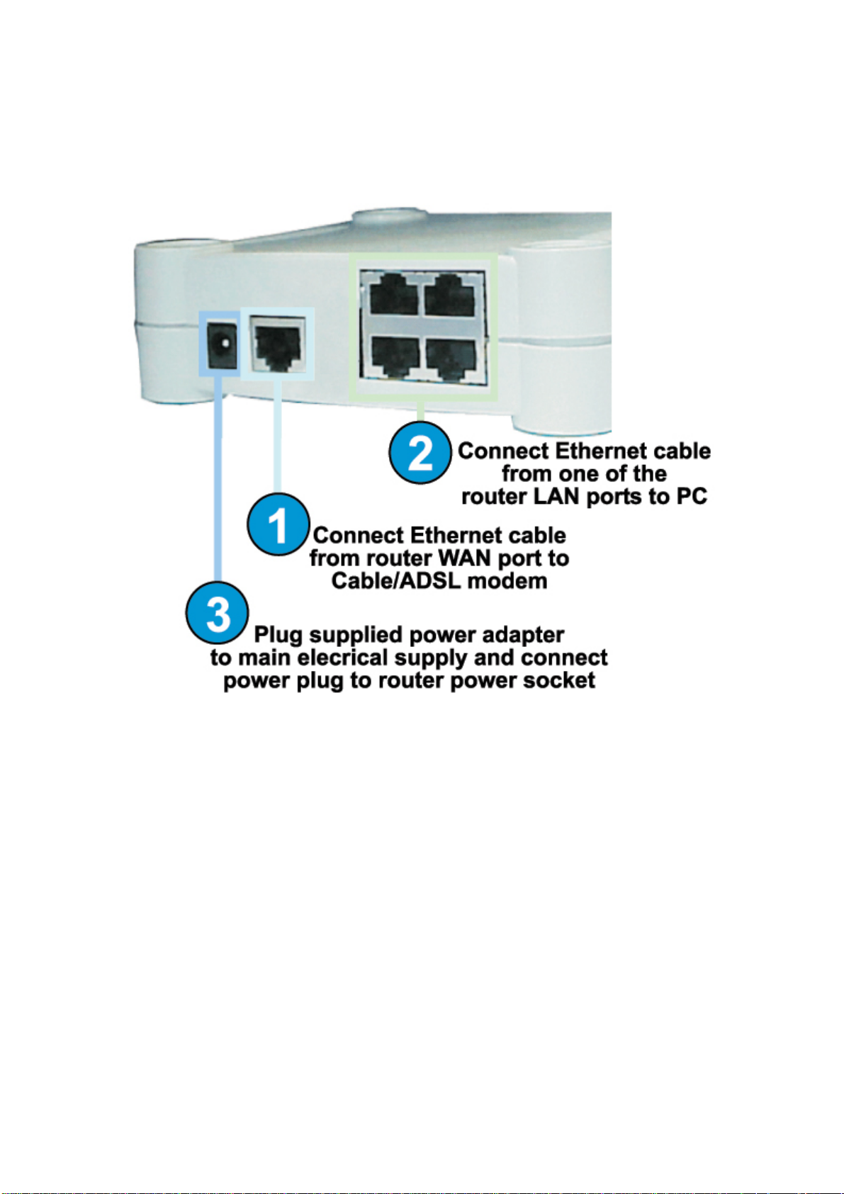
Install the Hardware
Page 6
Page 12
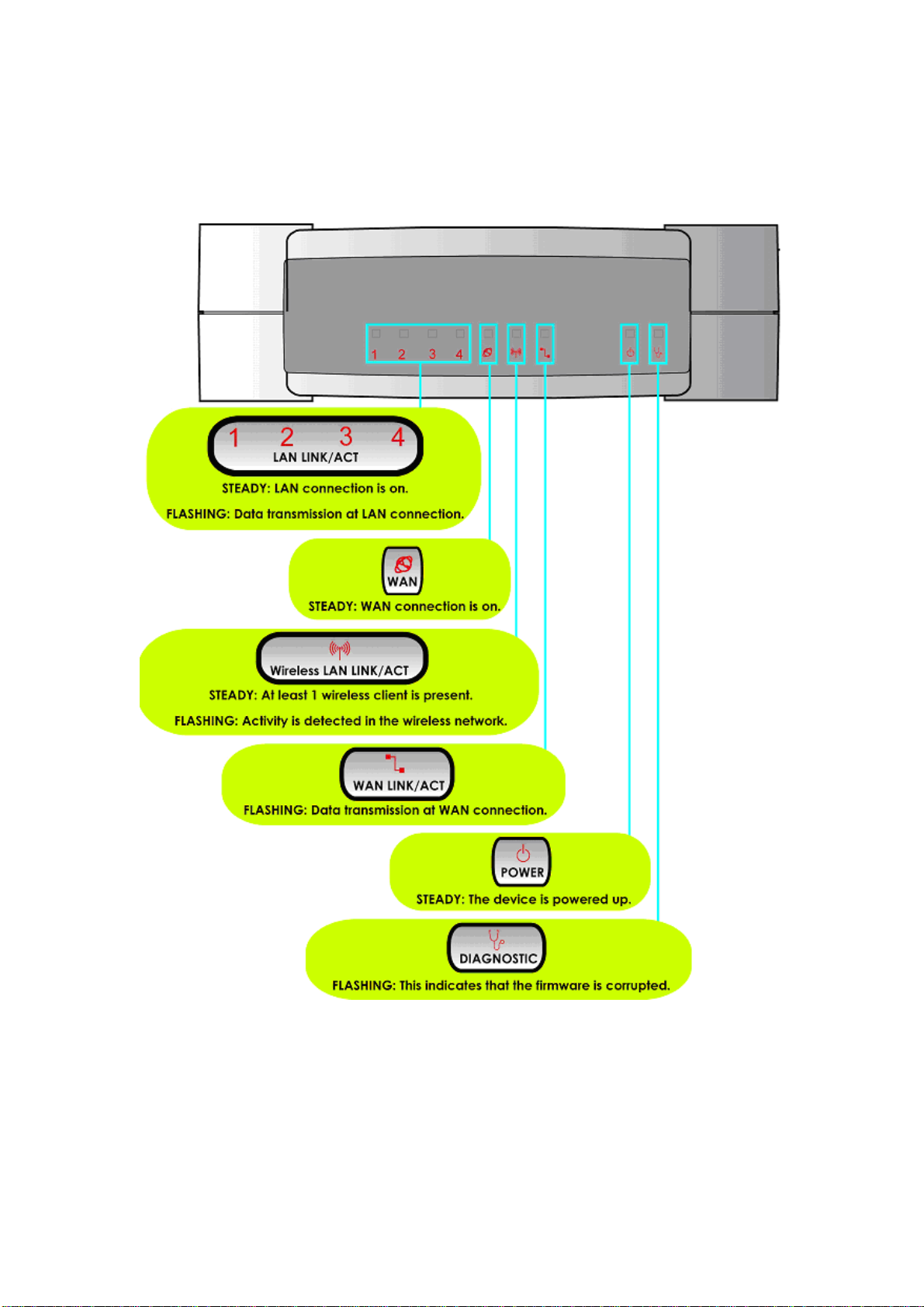
Overview the LEDs
Page 7
Figure 1
Page 13

Setup the Software
PC Configuration
Configuring PCs to be Wired to the Router
The first step is to make sure the PC gets an IP address that it will use to
communicate with the router and with other PCs across the network.
You can begin by setting up your PC to function as a DHCP client,
which will obtain an IP address automatically from router. Alternatively,
you may want to give your PC a static IP address if you are an expert
user.
Whether you choose to allocate static or dynamic IP settings, the next
few pages will walk you through the TCP/IP configuration in a step-bystep process. Depending on the Microsoft Windows operating system
used, you may skip some of the steps. Please ensure that you have an
Ethernet or wireless adapter successfully installed in each PC you are
configuring.
!
Important: By default, Windows 98SE, ME, 2000 and XP
have the TCP/IP protocol installed and set to obtain
an IP address automatically.
Page 8
Page 14
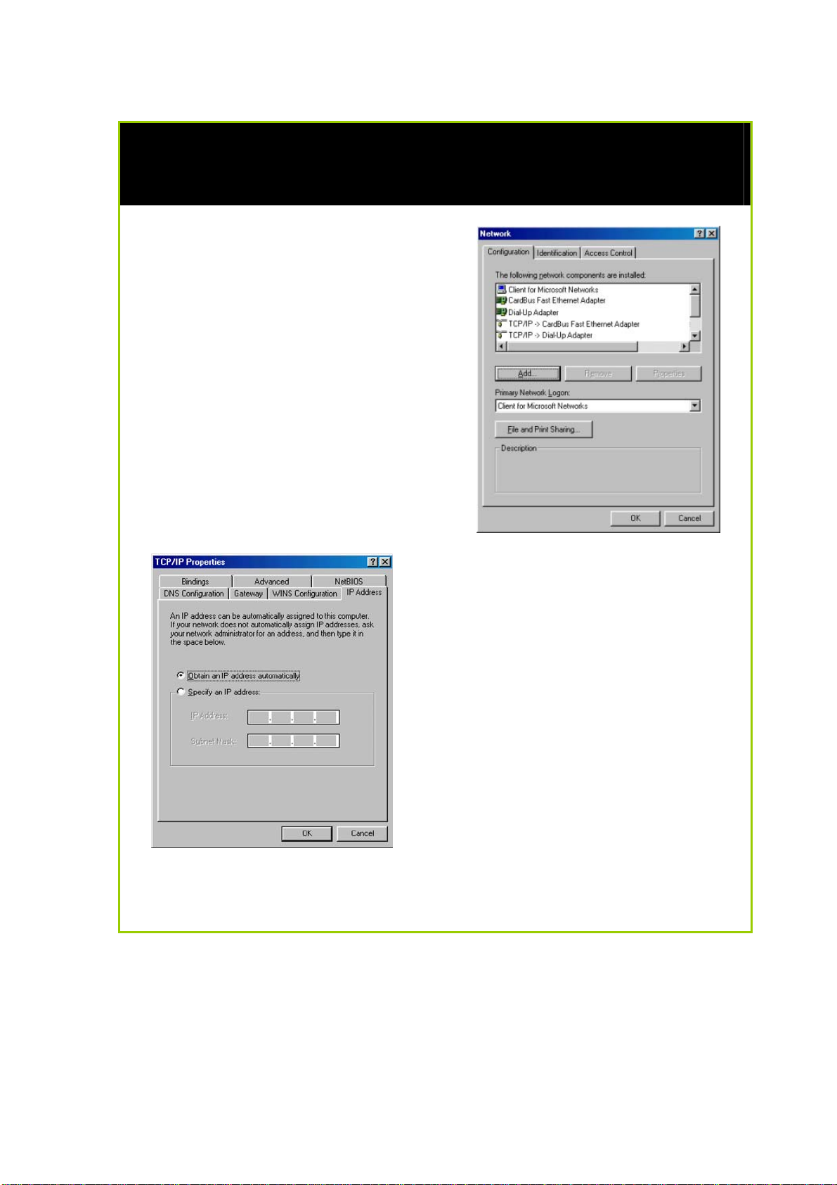
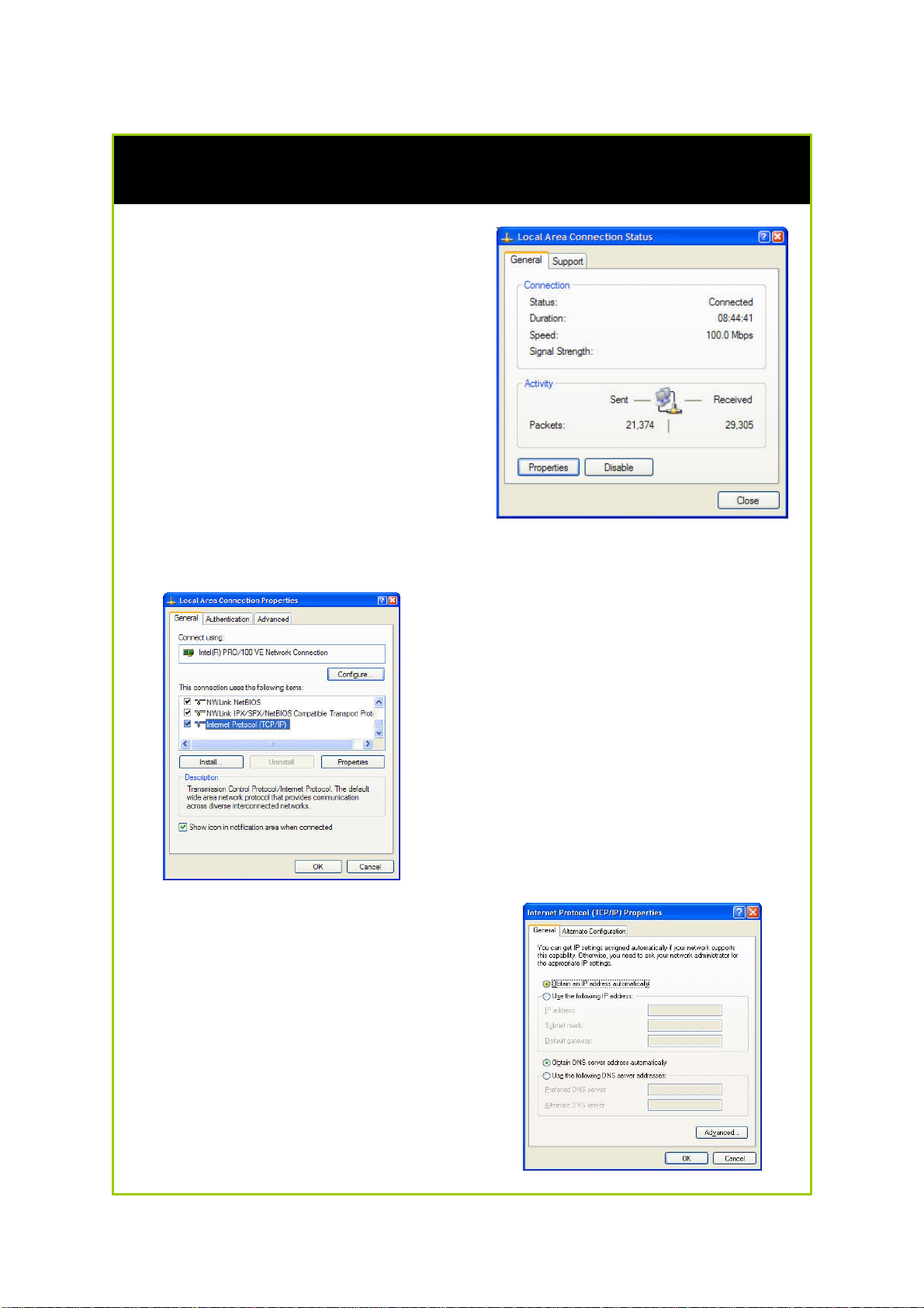
Configuring PC to dynamically obtain an IP address for Windows 98SE or
ME…
1. Click the Start button. Select
Settings and click the Control
Panel icon. Then double-click
the Network icon. You will see
the Network dialog on the right.
2. On the Configuration tab,
highlight the TCP/IP line
corresponding to your Ethernet
adapter and click on the
Properties button. You will be
brought to the TCP/IP Properties
page below.
3. Click on the IP Address tab, and
select Obtain an IP address
automatically.
4. Next, click the Gateway tab, and
verify that the Installed Gateway
field is blank. Now, click the OK
button
5. On the Network dialog page,
click on the OK button.
6. Windows may ask you to restart the PC, if so, click the Yes button and
allow the PC to restart in order to complete the configuration.
Page 9
Page 15
Configure PC to dynamically obtain IP address for Windows 2K or XP
1. Click the Start button. Select
Settings and click the Control
Panel icon. Then double-click
the Network and Dial-up
Connection (Windows 2000) or
Network Connection (Windows
XP) icon.
2. Double-click the Local Area
Connection icon for the network
adapter applicable to your
Internet connection, and click
the Properties button. You will
be brought to the dialog page
below.
3. On the General tab, make sure
the box next to Internet Protocol
(TCP/IP) is checked. Then
highlight Internet Protocol
(TCP/IP), and click the Properties
button.
4. Select Obtain an IP address
automatically.
Then click the OK button on this
page, and the OK button on the
previous page it returns you to.
Page 10
Page 16
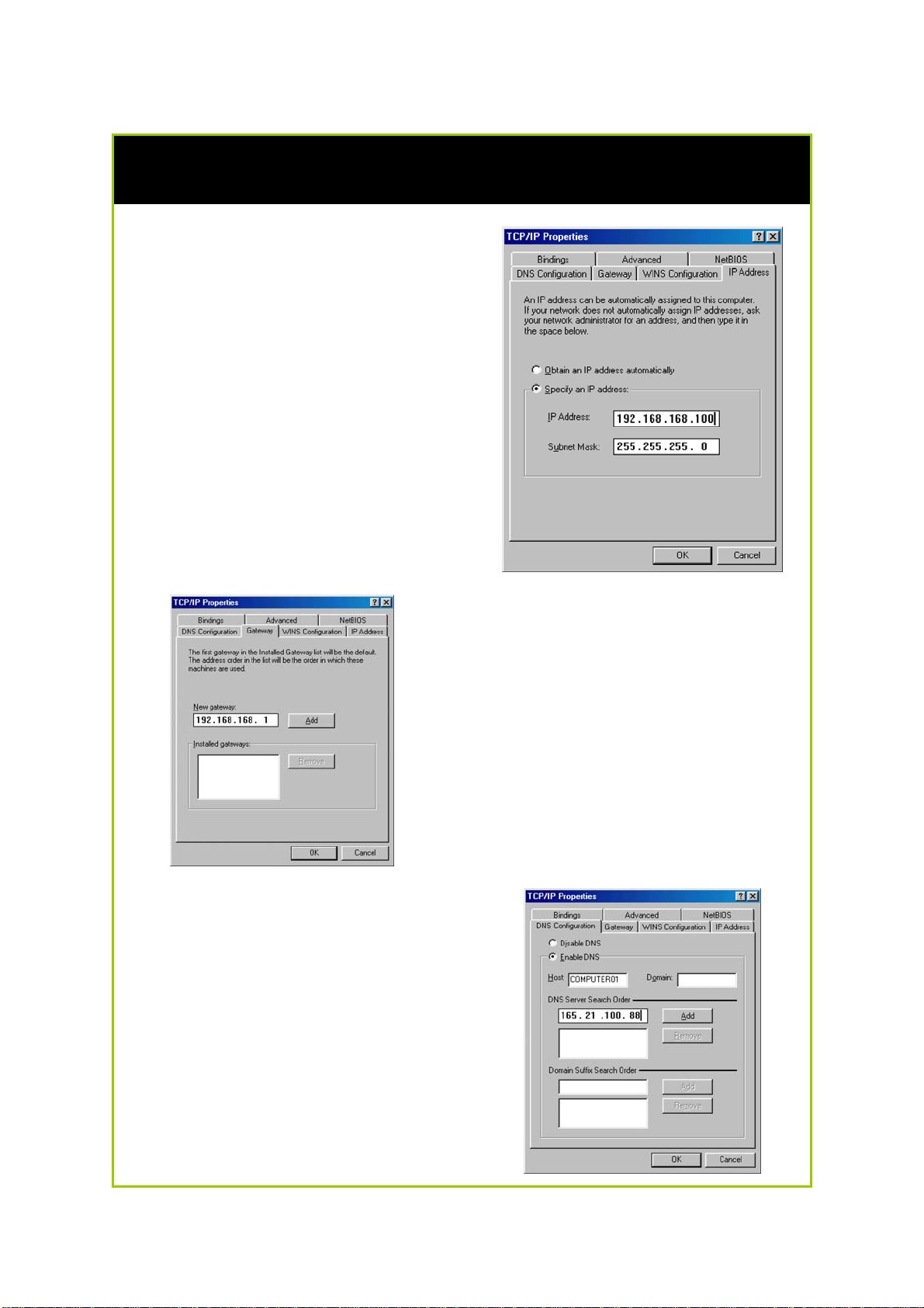
Configure PC with static IP address for Windows 98SE or ME
1. To begin the Static IP address
configuration, follow steps 1 & 2
of Part 1(a) to get to the page
on the right.
2. Click on the IP Address tab.
Then type in an IP address and
Subnet Mask as 192.168.168.X
and 255.255.255.0 respectively,
where X is any number from 2 to
254.
(Note that the default IP address of
the router is 192.168.168.1)
3. Next, click the Gateway tab to
see the dialog page on the left.
4. Under the New Gateway field,
key in the IP address of the router
(which is 192.168.168.1 by
default). Follow by clicking the
Add button.
5. Now, select the DNS
Configuration tab and on the
page you see, select Enable
DNS. Type in a preferred name
as the Host. Then, follow that up
by keying in the IP address of
your DNS Server in the DNS
Server Search Order field and
press the Add button.
6. You complete by clicking the
OK button, and then restarting
the computer.
Page 11
Page 17
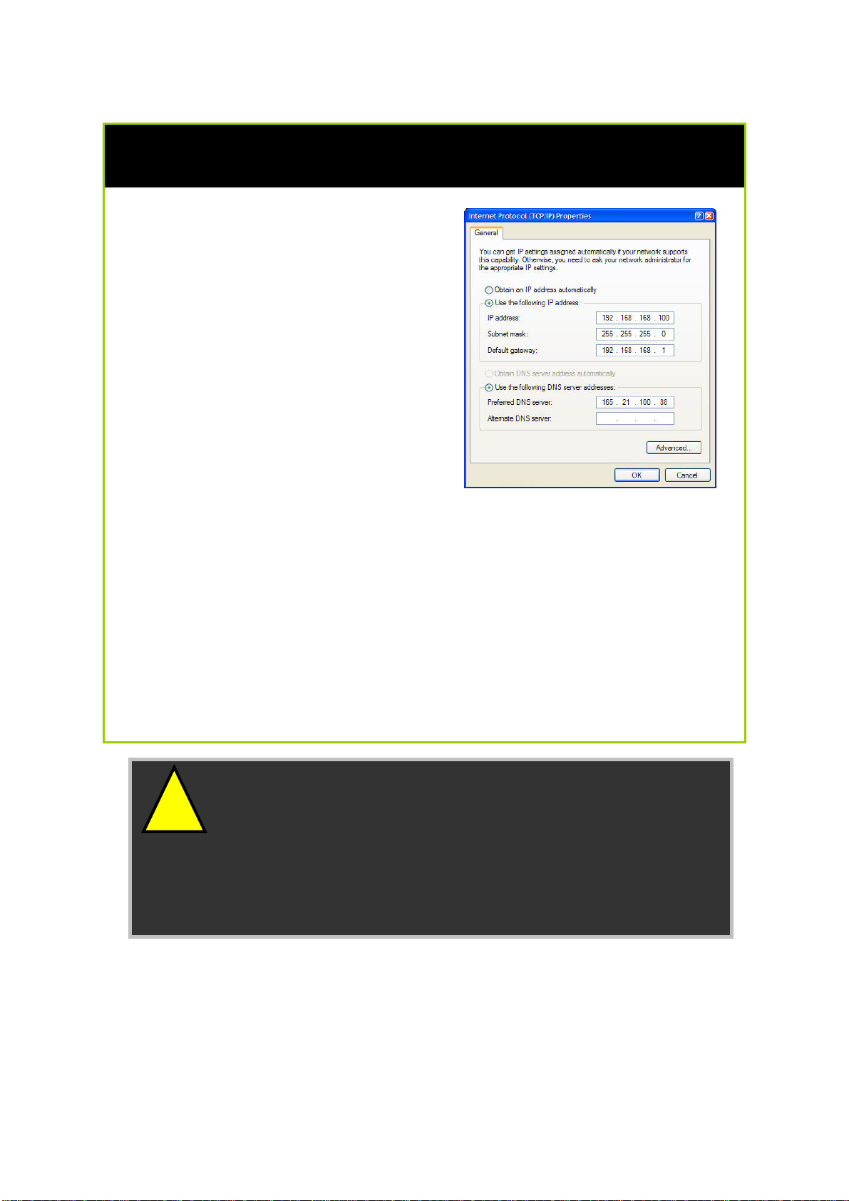
Configure PC with static IP address for Windows 2K or XP
1. To begin the Static IP address
configuration, follow steps 1, 2 &
3 of Part 1(b) to get to the page
on the right.
2. Select Use the following IP
address, and then key in
192.168.168.X for the IP address
field, where X is any number
from 2 to 254. Following that,
enter 255.255.255.0 for the
Subnet mask, and key in the IP
address of the router as the
Default gateway.
(Note that the default IP address of
the router is 192.168.168.1)
3. Now select Use the following
DNS server addresses, and then
key in the IP address of your DNS
server in the Preferred DNS
server field. Finally, click the OK
button to complete.
!
Important: You should not configure more than one
computer with the same IP address or the same host
name within a network. This will result in a conflict.
Your Internet Service Provider (ISP) should provide the
DNS Server’s IP address. If you are unsure about it, please
contact your ISP.
Page 12
Page 18

Configuring PCs to be Wireless Clients
The first step is similar to that of wired PCs connected to the Fast
Ethernet. We have to ensure that the wireless client gets an IP address
that it will use to communicate with the router and other PCs across the
network.
Hence, please note that in Windows XP, you will need to select the
wireless network connection corresponding to the wireless adapter you
use.
Once you have completed the IP configuration for the wireless client,
you may proceed to set up your wireless client’s SSID (Network name)
so that it will connect with the router.
!
Note for Windows 98SE/ME/2000 users: the following
configuration steps for wireless client setup may differ for
different wireless Ethernet adapters with vendor specific
driver and utilities. Please refer to your adapter’s manual
for more information.
Page 13
Page 19
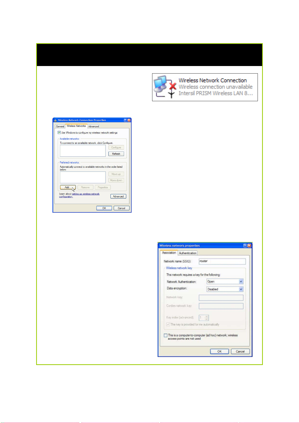
Configure Wireless Client for Windows XP
1. Right-click on Wireless Network
Connection corresponding to
the wireless adapter you wish to
connect with the router, and
click on Properties.
2. On the dialog box presented,
click the Wireless Networks tab,
and click on the Add button.
3. Next, key in the Network name
(SSID) of the wireless network. It
must be the same as the SSID of
the router in Part 2. For illustration
purpose, we typed router, which
is the default SSID for the router
(Take note that the SSID is casesensitive).
Ensure that the Network name
(SSID) value is the same for all the
wireless clients in the same wireless
network.
For now, you may leave the other
information as default (Network
Authentication -> Open; Data
encryption -> Disabled).
Page 14
Page 20

Perform Basic Router Setup
In this basic setup, you will find information on how you may configure
the router to function in your network and to access the Internet.
Use UConfig
The powerful uConfig utility has been developed to provide you hassle-free
access to the router’s web-based configuration page. If you do not wish to
modify the TCP/IP settings of your PC, or you have changed but forgotten
the router’s management IP address, uConfig will bring you to the router’s
setup – every time! It is simple. Ensure that your PC is connected to one of
the LAN ports of the router. Follow the 3 simple steps below.
Step 1:
Insert the Product CD into your CD-ROM drive. The CD will autorun to the
Welcome Page.
Step 2:
Click on Utilities and then click on uConfig to run it. You will see the
following screen:
Page 15
Page 21
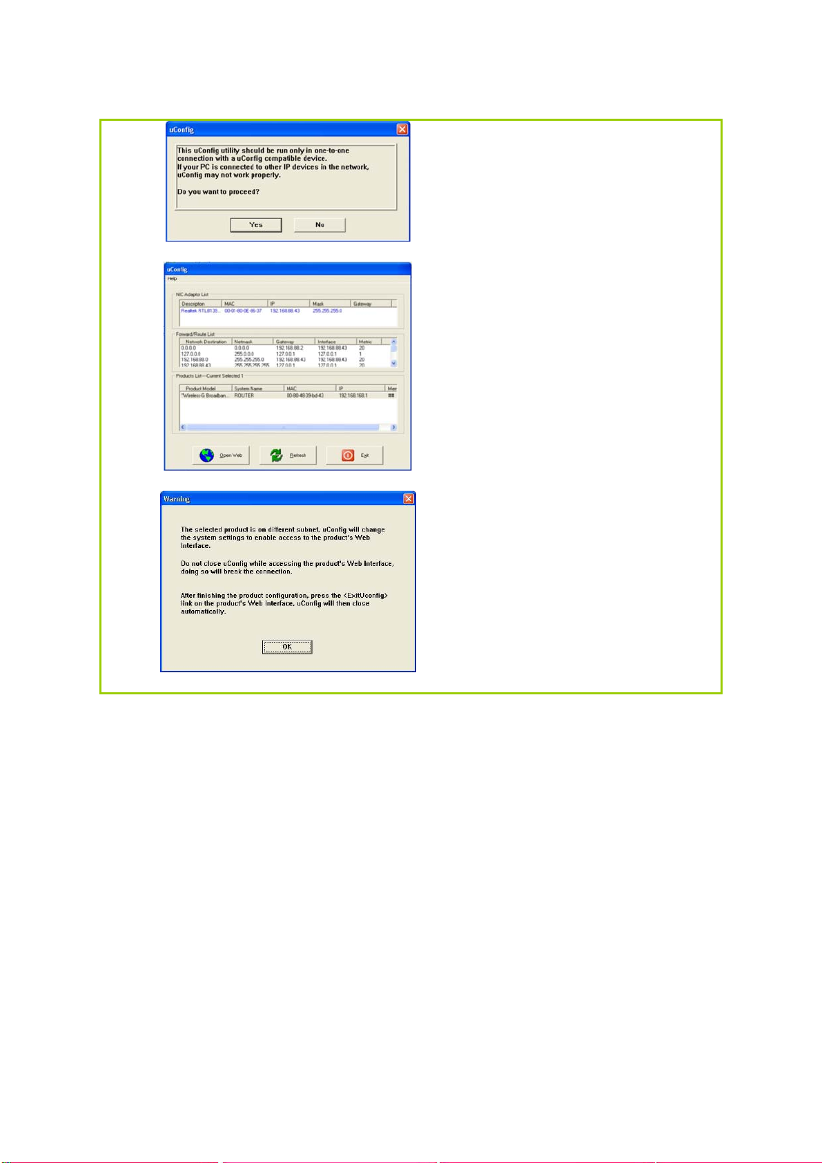
Step 3:
When the uConfig window is
prompted, click Yes to
proceed. With the router
selected under Products List,
click on Open Web. Click on
OK and you are done!
Page 16
Page 22
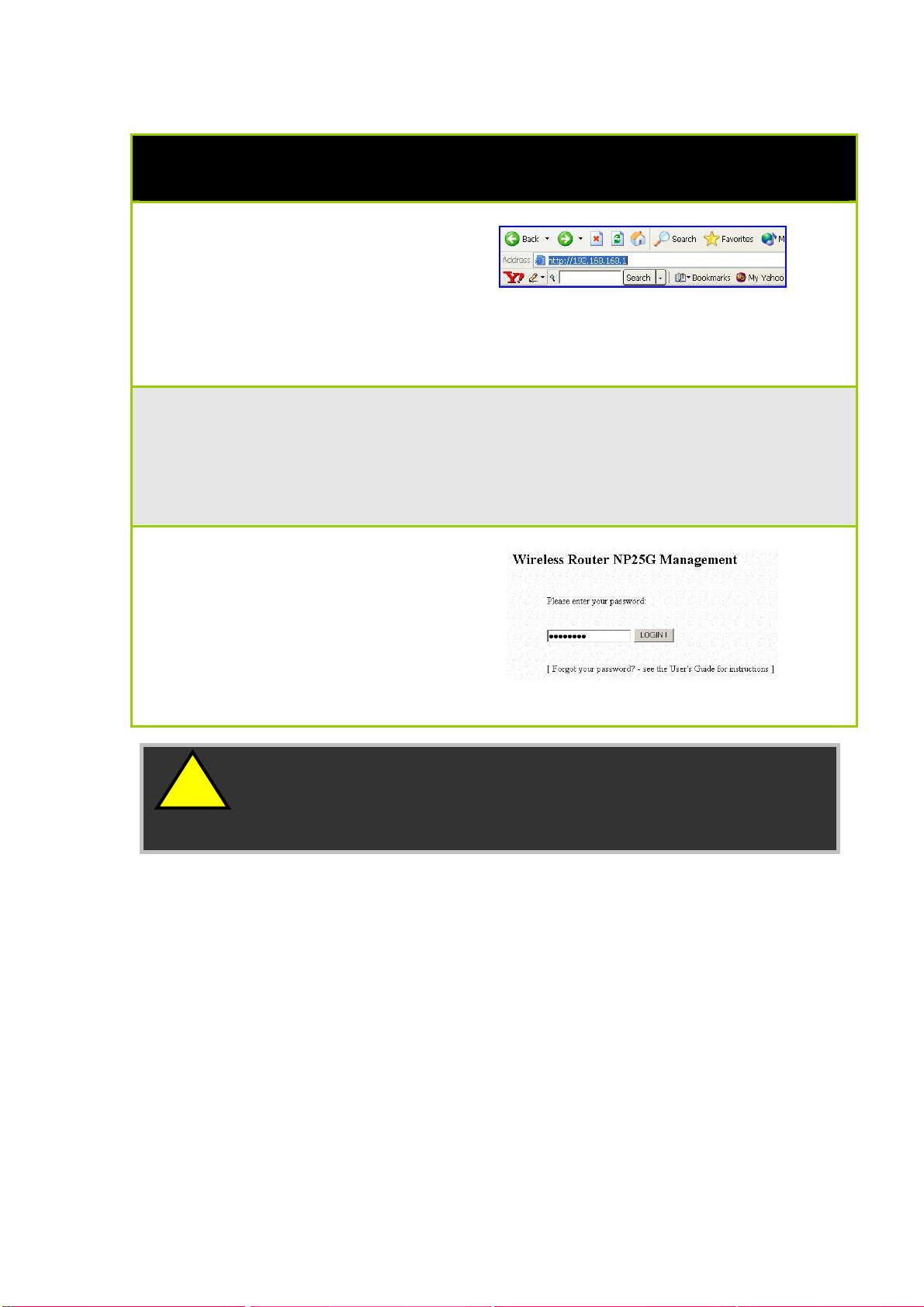
Access Web Interface
1. Open your web browser.
At the Address bar, enter
the IP address of the
router, as
http://192.168.168.1 and
hit the Enter key.
Note: If your PC has a TCP/IP setting differing from the steps described in Part
1, or if you have changed but forgotten the management IP of the router, you
may be unable to access the web-configuration page with step 1. The
powerful uConfig utility has been developed to bring you directly to the router
setup.
2. The default password is
pre-entered in the field
provided. Just click on the
LOGIN! button to access
the main page of the
router. The default
password is ‘password’
!
Note: The factory default password to access the webbased interface is <password>. It is recommended that you
change to another stronger password by following the steps
described in section System Tools : Change Password.
Page 17
Page 23
Setup Secured Wireless Connection
Setup Secured Wireless Connection
A secondary SSID which by default has no wireless security enabled is
available for connection setup.
This section will show how to setup a secured wireless connection like
WPA-Personal security. For other security modes, please refer to the Set
Security Mode section.
Setup Secured Wireless Connection without Wireless One-Touch Registration
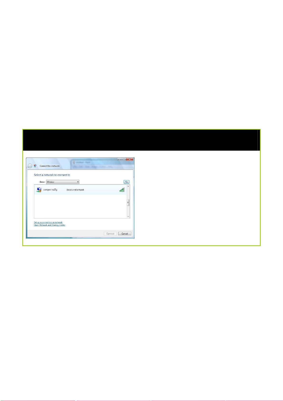
Step 1:
In the Connect to a network
configuration page, select the
secondary SSID (compex-np25g) and
click the Connect button.
Page 18
Page 24
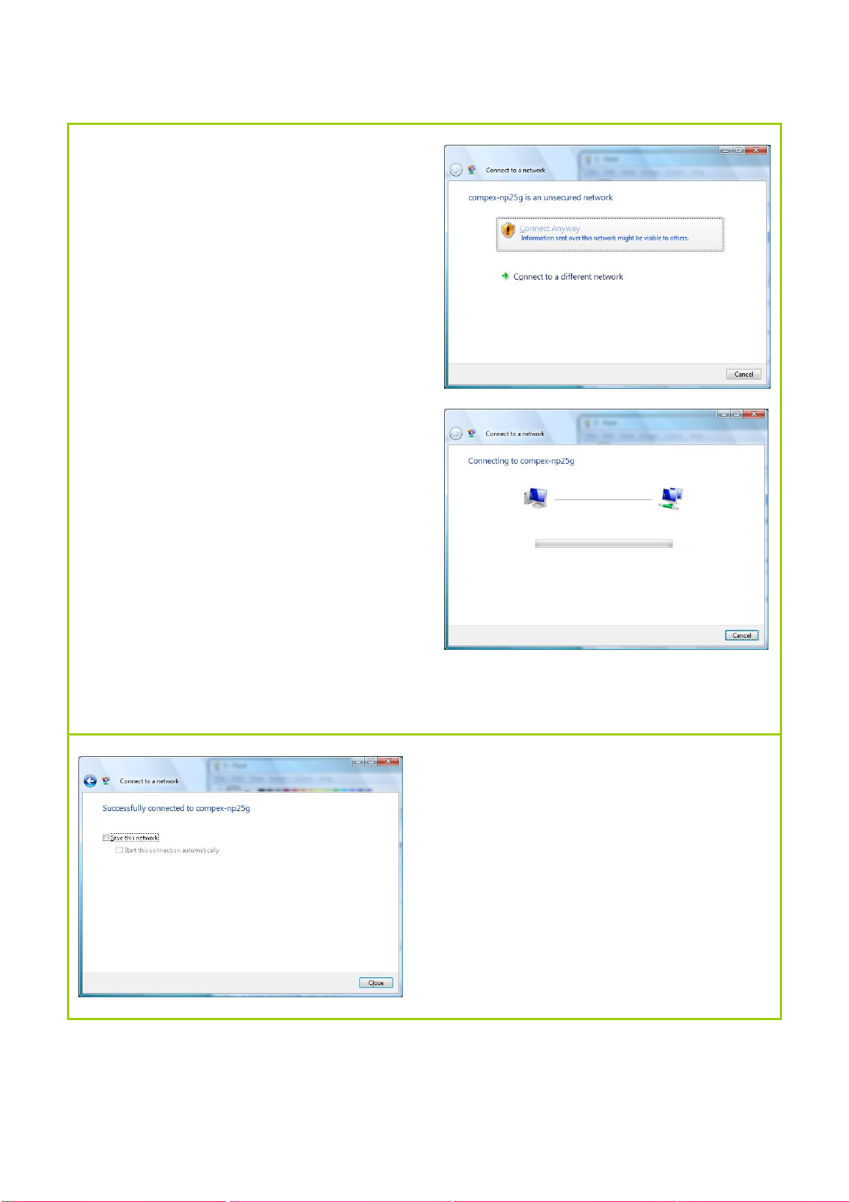
Step 2:
Click the Connect Anyway button
when prompted.
Connection to the secondary SSID
(compex-np25g) will commence.
Step 3:
Click the Close button to complete the
connection.
Page 19
Page 25
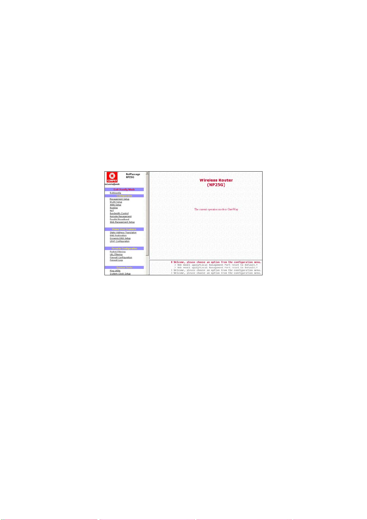
Perform Configuration
This part of the setup for the router is meant for the advanced user who
requires more than the essential information to set up a wired/wireless
network infrastructure. Adopting a top-down approach to explain the
features found on the router, what follows is a detailed walkthrough of
the configurable settings available within the web-based
administration menu:
Once you have successfully logged in, you shall find a comprehensive
list of configurable features as shown.
Page 20
Page 26

Configure Wireless Setup
The router supports wireless
LAN connectivity that is fully
compliant with the IEEE
802.11g and IEEE 802.11b
standards.
ESSID : Enter a preferred name for the wireless network.
Your wireless clients must be configured with the
same ESSID (or sometimes simply referred to as
SSID).
Wireless Profile
Country : This is where you are located during the
: Select from the list of wireless modes available:
a. 802.11b only
This mode supports wireless B clients with data
rates of up to 11Mbps in the frequency range of
2.4Hz.
b. 802.11g only
This mode supports wireless G clients with data
rates of up to 54Mbps in the frequency range of
2.4Hz.
c. 802.11b/g mixed
This mode supports both wireless B and G clients.
The basic rates are 1Mbps, 2 Mbps, 5.5 Mbps,
11Mbps, 6 Mbps, 12 Mbps and 24 Mbps.
connection.
Channel : This option allows you to select a frequency
channel for the wireless communication.
Tx Rate : This option allows you to select a specific transmit
power for the wireless communication. The
Transmit Power controls the signal strength
transmitted by the antenna. If the antenna has a
weak RF coverage, increase the Transmit Power. If
the antenna has a strong RF coverage, decrease
the Transmit Power.
Page 21
Page 27

Set Security Mode
Security plays a vital role in securing wireless 802.11 networks to prevent
unauthorised users from accessing and using the network resources.
Disable Security
To disable the Security mode (not recommended), follow these instructions:
Under the CONFIGURATION
command menu, you will find the
Wireless Setup page. Click on the
Change button next to the
Security mode. Then check the
radio button next to Disable,
followed by the Apply button.
Page 22
Page 28

Setup WEP
Wired Equivalent Privacy is implemented in the network. It is a security
protocol in a wireless local area network.
To set the Security mode to WEP, follow these instructions:
You can define up to 4 WEP keys.
Click Edit to set the keys.
For hexadecimal key entry:
1. Select the Hex radio button.
2. Select the radio button of the key to
be entered.
3. Select the key encryption mode
from the drop down menu.
4. Fill in the key value.
A hexadecimal value is made of digits 0-9
and letters A-F, and is NOT case-sensitive.
For 64-bit encryption:
Your WEP key has to be 10 hex digits
long.
For 128-bit encryption:
Your WEP key has to be 26 hex digits
long.
5. Click on Apply.
6. If the key format is valid, the page
will refresh and the key will appear in
encrypted form.
Page 23
Page 29

For ASCII key entry:
1. Select the ASCII radio button.
2. Select the radio button of the
key to be entered.
3. Select the key encryption
mode from the drop down
menu.
4. Fill in the key value.
An ASCII value can take in any
alphanumeric character and is NOT
case-sensitive.
For 64-bit encryption:
Your WEP key has to be 5
characters long.
For 128-bit encryption:
Your WEP key has to be 13
characters long.
5. Click on Save.
6. If the key format is valid, the
page will refresh and the key
will appear in encrypted form.
To add more hexadecimal WEP keys,
repeat step 2.
To add more ASCII WEP keys, repeat step
2.
You can set a maximum of 4 WEP keys
using different key entry methods and
encryption levels.
To specify which key to use:
1. Select the radio button of the key to
be used.
2. Click on Apply, then on Reboot to
apply the changes.
Page 24
Page 30

Setup WPA
Follow these steps to setup the router for using WPA Personal, WPA2
Personal, and WPA Auto Personal.
At the WWPPAA11//22--PPSSKK SSeettuupp page,
SStteepp 11::
Specify the kkeeyy eennttrryy ttyyppee, by selecting either:
•
•
PPaasssspphhrraassee ((AAllpphhaannuummeerriicc cchhaarraacctteerrss))
•
•
HHeexxaaddeecciimmaall
SStteepp 22::
Fill in the pre-shared network key:
If you are using the PPaasssspphhrraassee format, your entry can consist of a minimum of 8
alphanumeric characters or a maximum of 63 alphanumeric characters.
Otherwise, when using the HHeexxaaddeecciimmaall format, your entry MUST
consist of 64
hexadecimal characters.
SStteepp 33::
For WPA-Personal
Set the CCiipphheerr TTyyppee to TTKKIIPP.
WPA replaces WEP with a strong encryption technology called Temporal Key
Integrity Protocol (TKIP) with Message Integrity Check (MIC).
For WPA2-Personal
Set the CCiipphheerr TTyyppee to AAEESS.
Advanced Encryption Standard (AES) is a stronger symmetric 128-bit block data
encryption technique. AES is a requirement of WPA2 under the IEEE 802.11i
standard.
For WPA-Personal-AUTO
Set the CCiipphheerr TTyyppee to AAuuttoo to allow the router to automatically detect the cipher
type to use.
Page 25
Page 31

SStteepp 44::
Enter the GGTTKK ((GGrroouupp TTrraannssiieenntt KKeeyy)) UUppddaatteess.
This is the length of time after which the router will automatically generate a new
shared key to secure multicast/broadcast traffic among all stations that are
communicating with it. By default, the value is 600 seconds.
SStteepp 55::
Click the AAppppllyy button and reboot your system, after which your settings will
become effective.
Page 26
Page 32

Configure the Advanced WLAN Settings
Follow these steps to change the radio settings of the router.
1. Click on WLAN Setup from the
CONFIGURATION menu.
2. Select Advanced.
1. Click Apply.
Changes will be enabled after reboot.
1. Set the Beacon Interval (the time
lapse between every beacon sent)
to any value between 20 and 1000.
It is preset as 100 seconds.
2. Set the Data Beacon Rate from 1 to
16384.
This determines how often the
beacon should contain a Delivery
Traffic Indication Message (DTIM)
that tells power-save clients that a
packet is waiting for them. Is it preset
to 1.
3. Set the RTS/CTS Threshold from 256 to
2346.
It is preset to 2346.
4. Set the Frag Threshold from 256 to
2346.
It is preset to 2346.
5. Transmission Power Control (TPC)
offers the flexibility to set the Transmit
Power. (802.11h compliant)
It is set to Maximum by default, but
should be reduced if there is more
than one unit using the same
channel frequency.
It can be set from Minimum to
Maximum, 1dBm to 20dBm, in
increments or 1dBm per step.
Page 27
Page 33

Set Wireless Multimedia
Wireless Multimedia (WMM) is a QoS (Quality of Service) standard in
IEEE802.11E that we have adopted to improve and support the user
experience for multimedia, video, and voice applications by pri oriti zing
data traffic. QoS can be realized through 4 different Access Categories
(AC). Each AC type consists of an independent transmit queue, and a
channel access function with its own parameters.
Page 28
Page 34

Follow these steps to change the setup Wireless Multimedia on your
router.
1. Click on WLAN Setup from the CONFIGURATION menu.
2. Select Advanced.
Click WMM Settings.
1. Select to Enable Wireless Multimedia
(WMM)
2. Enter the desired WMM parameters.
Using the default parameters is
recommended.
3. Click Apply to apply the WMM
settings, click Default to reset all
parameters to default, or click Back
to discard any changes and return
to WLAN Basic Setup page.
Page 29
Page 35

WMM Parameters (for advanced users)
AIFs (Arbitrary
Inter-Frame
Space)
Cwmin
(Contention
Window
Minimum)
CwMax
(Contention
Window
Maximum)
TxOp limit
(Transmit
Opportunity
Limit)
NoAck (No
Acknowledgeme
nt)
ACM (Admission
Control
Mandatory)
BE (Best Effort)
BK (Background)
VI (Video )
VO (Voice) Parameters for voice data traffic.
Arbitrary Inter-Frame Space is the minimum wait
time interval between the wireless medium
becoming idle and the start of tr ansmission of a
frame over the network.
Contention Window Minimum is the minimum
random wait time drawn from this interval or
window for the backoff mechanism on the network.
Contention Window Maximum is the maximum
random wait time drawn from this interval or
window for the backoff mechanism on the network.
Transmit Opportunity limit specifies the minimum
duration that an end-user device can transmit data
traffic after obtaining a transmit opportunity. TxOp
limit can be used to give data traffic longer and
shorter access.
No Acknowledgement provides control of the
reliability of traffic flow. Usually an acknowledge
packet is returned for every packet received,
increasing traffic load and decreasing
performance.
Enabling No Acknowledgement cancels the
acknowledgement. This is useful for data traffic
where speed of transmission is important.
Admission Control Mandatory enables WMM on the
radio interface. When ACM is enabled, associated
clients must complete the WMM admission control
procedure before access.
Parameters for Data0 Best Effort.
Best Effort data traffic has no prioritization and
applications equally share available bandwidth.
Parameters for Data1 Background.
Background data traffic is de-prioritized and is
mostly for backup applications, or background
transfers like backup applications or background
transfers like bulk copies that do not impact
ongoing traffic like Internet downloads.
Parameters for video data traffic.
Page 30
Page 36

Setup WDS2
WDS2 (Wireless Distributed System 2) links up access points to create a
wider network in which mobile users can roam while still staying
connected to available network resources. The wireless client and root
access point has to be set up with the same channel frequency. This
allows them to connect even when the link is lost, as the channel
frequency setting is preserved.
In this example, there are 2 access points: Access Point 1 and Access
Point 2, with Access Point 1 as the root access point.
Page 31
Page 37

Follow these steps to change the setup the root access point.
SSeettuupp aacccceessss ppooiinntt 11::
Click on WWLLAANN SSeettuupp from the CCOONNFFIIGGUURRAATTIIOONN menu. You will see the sub-menus
expanded under WWLLAANN SSeettuupp. Click on BBaassiicc.
Ensure that TThhee CCuurrrreenntt MMooddee is se
t to AAcccceessss PPooiinntt.
Select AAcctt aass RRoooottAAPP.
Select the CChhaannnneell common to both access point 1 and access point 2.
Page 32
Page 38

Follow these settings to setup access point 2.
SSeettuupp aacccceessss ppooiinntt 22::
Click on WWLLAANN SSeettuupp from the CCOONNFFIIGGUURRAATTIIOONN menu. You will see the sub-menus
expanded under WWLLAANN SSeettuupp. Click on BBaassiicc.
Select the CChhaannnneell common to both access point 1 and access point 2.
Page 33
Page 39

CCoonnffiigguurree WWDDSS22 lliinnkk::
Click on WWLLAANN SSeettuupp from the CCOONNFFIIGGUURRAATTIIOONN menu. You will see the sub-menus
expanded under WWLLAANN SSeettuupp. Click on AAddvvaanncceedd.
Under EExxtteennddeedd FFeeaattuurreess, click on the WWDDSS22 SSeettttiinnggss button.
Set WWDDSS22 LLiinnkk SSttaattuuss to EEnnaabbllee.
ions for configuring WDS2 link:
Opt
• By Remote AP MAC – Enter the Remote AP MAC
OR
• By Remote AP SSID – Uncheck the Remote AP MAC checkbox and enter the
Remote AP SSID.
Apply..
CClliicckk
Page 34
Page 40

Setup Management Port
Follow these steps to define the IP addresses.
SStteepp 11::
Click on TTCCPP//IIPP SSeettttiinnggss from MMaannaaggeemmeenntt SSeettuupp from the CCOONNFFIIGGUURRAATTIIOONN menu.
SStteepp 22::
In the MMaannaaggeemmeenntt PPoorrtt SSeettuupp page, refer to the table below to replace the default
settings with appropriate values to suit the needs of your network.
SStteepp 33::
Click on the AAppppllyy button to save your new parameters.
This table describes the parameters that can be modified in the
Management Port Setup page.
Parameters Description
IP Address When the DHCP server of the router is enabled (unless you
set a different DHCP Gateway IP Address), this LAN IP
Address would be allocated as the Default Gateway of the
DHCP client.
The IP address is set by default to 192.168.168.1.
Network
Mask
Primary DNS
IP Address
Secondary
DNS IP
Address
The Network Mask serves to identify the subnet in which your
router resides. The default network mask is 255.255.255.0.
Your ISP usually provides the IP address of the DNS server.
This optional field is reserved for the IP address of a
secondary DNS server.
Page 35
Page 41

To Setup DHCP Server
There are 3 DHCP Modes:
• NONE
Select NONE if you do not wish to use a DHCP server.
• DHCP Server
Select this mode to setup a DHCP server.
• DHCP Relay
Select this mode to setup a DHCP relay.
By default, DHCP broadcast messages do not cross router
interfaces.
DHCP Relay supports DHCP Clients and DHCP Servers on different
networks by configuring the router to pass selective DHCP
messages.
Follow these steps if you do not wish to use DHCP.
SStteepp 11::
Click on AAddvvaanncceedd SSeettttiinnggss from MMaannaaggeemmeenntt SSeettuupp from the CCOONNFFIIGGUURRAATTIIOONN
menu.
SStteepp 22::
Set DDHHCCPP MMooddee to NNOONNEE.
SStteepp 33::
Click on the AAppppllyy button.
Page 36
Page 42

The following will guide you to setup the DHCP Server.
SStteepp 11::
Click on AAddvvaanncceedd SSeettttiinnggss from MMaannaaggeemmeenntt SSeettuupp from the CCOONNFFIIGGUURRAATTIIOONN
menu.
SStteepp 22::
Set DDHHCCPP MMooddee to DDHHCCPP SSeerrvveerr.
In DDHHCCPP SSeerrvveerr SSeettuupp, refer to the table below to set the appropriate values to suit
the needs of your network.
SStteepp 33::
Click on the AAppppllyy button.
Page 37
Page 43

This table describes the parameters that can be modified in DHCP
Server Setup.
Parameters Description
The fields DHCP Start IP Address and DHCP End IP Address fields allow you to
define the range of IP addresses from which the DHCP Server can assign an IP
address to the LAN.
DHCP Start IP Address
DHCP End IP Address
DHCP Gateway IP
Address
This is the first IP address that the DHCP server will
assign and should belong to the same subnet as
the router. For example if the router IP address is
192.168.168.1 and the network mask is
192.168.168.1 and 255.255.255.0, the DHCP Start IP
Address should be 192.168.168.X, where X can be
any number from 2 to 254. It is pre-set to
192.168.168.100.
This is the last IP address that the DHCP server can
assign and should also belong to the same subnet
as your router. For example if the router IP address
is 192.168.168.1 and the network mask is
192.168.168.1 and 255.255.255.0, the DHCP End IP
Address should be 192.168.168.X, where X can be
any number from 2 to 254. It is pre-set as
192.168.168.254.
Though the DHCP server usually also acts as the
Default Gateway of the DHCP client, the router
allows you to define a different Gateway IP
Address which will be allocated as the Default
Gateway IP of the DHCP client. The DHCP client
will thus receive its dynamic IP address from the
router but will access to the Internet or the other
LAN through the Default Gateway defined by the
DHCP Gateway IP Address.
For instance if the unit in Access Point Client mode
connects to an Internet gateway X, a PC wired t o
the unit will be unable to obtain a dynamic IP
address directly from X. But if you enable the
DHCP server of the unit and set the IP address of X
as the DHCP Gateway IP Address, the PC will
obtain its IP address from the unit and access the
Internet through X.
Page 38
Page 44

DHCP Lease Time
Always use these DNS
servers
Primary DNS IP Address
Secondary DNS IP Address This optional setting is the IP address of a
This is the length of time that the client may use
the assigned address before having to check with
the DHCP server to see if the Address is still valid.
Enable this checkbox if you only want to use the
DNS server(s) you have specified.
Your ISP usually provides the IP address of the DNS
server.
secondary DNS server.
Page 39
Page 45

The following will guide you to setup the DHCP Relay.
SStteepp 11::
Click on AAddvvaanncceedd SSeettttiinnggss from MMaannaaggeemmeenntt SSeettuupp from the CCOONNFFIIGGUURRAATTIIOONN
menu.
SStteepp 22::
Set DDHHCCPP MMooddee to DDHHCCPP RReellaayy.
In DDHHCCPP SSeerrvveerr SSeettuupp, refer to the table below to set the appropriate values to suit
the needs of your network.
SStteepp 33::
Click on the AAppppllyy button.
Page 40
Page 46

This table describes the parameters that can be modified in DHCP
Server Setup.
Parameters Description
DHCP Server IP
DHCP Gateway IP Though the DHCP server usually also acts as the
This is the IP address of the DHCP server.
Default Gateway of the DHCP client, the router
allows you to define a different Gateway IP
Address which will be allocated as the Default
Gateway IP of the DHCP client. The DHCP client
will thus receive its dynamic IP address from the
router but will access to the Internet or the other
LAN through the Default Gateway defined by
the DHCP Gateway IP Address.
For instance if the unit in Access Point Client
mode connects to an Internet gateway X, a PC
wired to the unit will be unable to obtain a
dynamic IP address directly from X. But if you
enable the DHCP server of the unit and set the IP
address of X as the DHCP Gateway IP Address,
the PC will obtain its IP address from the unit and
access the Internet through X.
Page 41
Page 47

View Active DHCP Leases
SStteepp 11::
Select MMaannaaggeemmeenntt SSeettuupp from the CCOONNFFIIGGUURRAATTIIOONN menu.
SStteepp 22::
Go to the AAddvvaanncceedd DDHHCCPP SSeerrvveerr OOppttiioonnss section and click on the SShhooww AAccttiivvee
DDHHCCPP lleeaassees
The DHCP Active Leases table displays:
• The Host Name of the DHCP client.
• The IP Address allocated to the DHCP client.
• The Hardware (MAC) Address of the DHCP client.
• The Lease Expired Time.
s button.
NOTE
Invalid date and time displayed in the Lease Expired Time column
indicates that the clock of the router has not been set properly.
Page 42
Page 48

Reserve IP Addresses for Predetermined DHCP Clients
A reserved IP address is excluded from the pool of free IP addresses the
DHCP server draws on for dynamic IP address allocation.
For instance if you set up a publicly accessible FTP or HTTP server within
your private LAN, while that server requires a fixed IP address you would
still want the DHCP server to dynamically allocate IP addresses to the
rest of the PCs on the LAN.
SStteepp 11::
From the AAddvvaanncceedd DDHHCCPP SSeerrvveerr Options section click on the DDHHCCPP SSeerrvveerr
RReesseerrvvaattiioonnss
SStteepp 22::
Click on the AAdddd button.
button.
Page 43
Page 49

SStteepp 33::
Fill in:
The IP Address to be reserved.
The Hardware Address, in pairs of two hexadecimal values.
Press the AAppppllyy button to effect your new entry.
The DDHHCCPP SSeerrvveerr RReesseerrvvaattiioonnss page refreshes to display the currently
reserved IP addresses.
Page 44
Page 50

Delete DHCP Server Reservation
SStteepp 11::
Select the reserved IP address to delete.
SStteepp 22::
Click on the DDeelleettee button.
The DDHHCCPP SSeerrvveerr RReesseerrvvaattiioonnss table refreshes to display your changes.
Page 45
Page 51

View Statistics
Follow these steps to view the WLAN detailed connections statistics per
WLAN station.
1. Click on WLAN Setup from the
CONFIGURATION menu.
2. Select Statistics.
The WLAN connection’s statistics
displays.
Click Back to return to WLAN Basic
Setup page.
1. Select the WLAN connection to view
statistics of.
• Click Refresh to refresh the WLAN
Connection List.
• Click Back to return to the WLAN
Basic Setup page.
Page 46
Page 52

Setup WAN
A correct WAN Setup allows you to successfully share your Internet
connection among the wired and wireless clients of the router. To do
so, you need to identify the type of broadband Internet access you are
subscribed to:
i. Cable Internet where your ISP dynamically assigns a WAN IP
address
ii. Cable Internet where your ISP provides you with a fixed WAN IP
address (or a range of fixed IP addresses)
iii. ADSL Internet that requires standard PPP over Ethernet (PPPoE) for
authentication
iv. ADSL Internet that requires standard Point-to-Point Tunneling
Protocol (PPTP) for authentication.
v. ADSL Internet that requires standard Layer 2 Tunneling Protocol
(L2TP) for authentication. L2TP is an extensi on to the PPP protocol
that enables ISPs to operate VPNs. It is the best combination of
PPTP (from Microsoft) and L2F (from Cisco Systems). It has the
most similar parameters of the PPTP except that it does not
support the DHCP server.
Page 47
Page 53

Setup WAN for Cable Internet with Dynamic IP
Assignment
The router is pre-configured to support a WAN type that dynamically obtains an IP
address from the ISP. However, you may verify the WAN settings with the following
steps:
1. Under the CONFIGURATION
on the command menu, click
on WAN Setup.
2. On the WAN Dynamic Setup
screen that follows, verify that
the WAN Type reads Dynamic
(DHCP) in red colour.
Otherwise, click on the
Change button.
3. Simply select Dynamic IP
Address and hit the Apply
button.
4. Please remember to click
Reboot Router under SYSTEM
TOOLS and hit the Reboot
button to let the settings take
effect.
Page 48
Page 54

Note: There are exceptional cases where additional configuration is required before
your ISP allocates an IP address to the router.
b. Certain ISPs log the MAC address of the first device used to connect to the
broadband channel and will not release a WAN IP address unless the MAC
address matches the one in their log. Therefore, if yours is not a new Cable
Internet subscription (i.e. your PC was formerly connected directly to your
cable modem); refer to steps 5 - 7 to clone the “approved” MAC address
onto the router.
c. Certain ISPs require authentication through a DHCP Client ID before
releasing a public IP address to you. The router uses the System Name in
the System Identity as the DHCP Client ID.
Therefore, if this is the case, refer to your ISP for the correct DHCP Client ID
to be set and follow steps 8 - 10 to accomplish the setup.
5. Steps 5 - 7 are for those who
need to clone their Ethernet
adapter’s MAC address.
In the WAN Setup found under
the CONFIGURATION
command menu, click MAC
Clone to continue.
6. Simply click on the Clone
button so that your router
clones the ISP-recognized
MAC address of your Ethernet
adapter.
7. Please remember to click
Reboot Router under SYSTEM
TOOLS and hit the Reboot
button to let the settings take
effect.
Take note: (If required, you may reset the
router’s MAC address to its factory default
by clicking Reset on that same page)
Page 49
Page 55

Setup WAN for Cable Internet with Static IP
Assignment
If you have an ISP that leases a static WAN IP for your subscription, you will need to
configure your router’s WAN type accordingly. For example, if the ISP provided you
with the following setup information, you can set up your WAN as described below:
IP Address : 203.120.12.47
Network Mask : 255.255.255.0
Gateway IP Address : 203.120.12.15
1. Under the CONFIGURATION on the command menu, click on WAN Setup.
2. Access the Select WAN Type page
and choose Static IP Address before
clicking the Apply button. You will
then be brought to the following
page requiring your inputs.
3. Fill in the information provided by
your ISP in the IP Address, Network
Mask and Gateway IP Address
fields, before clicking the Apply
button.
4. Please remember to click Reboot
Router under SYSTEM TOOLS and hit
the Reboot button to let the settings
take effect.
Page 50
Page 56

Setup WAN for ADSL Internet Using PPPoE
If you subscribe to an ADSL service using PPP over Ethernet (PPPoE) authentication,
you can set up your router’s WAN type as follows. For example, you may configure
an account whose username is ‘guest’ as described below:
1. Under the CONFIGURATION on the
command menu, click on WAN
Setup.
2. Access the Select WAN Type page
and choose PPP over Ethernet before
3. For Username, key in your ISP
assigned account name (e.g.
guest for this example), followed
by your account Password.
4. Select Always-On if you want your
router to always maintain a
connection with the ISP. Otherwise,
you may select On-Demand. The
router will then connect to the ISP
automatically when it receives
Internet requests from the PCs in
your network.
The Idle Timeout setting is associated with the On-Demand opti on, allowing you to
specify the value (in seconds) after which the router will disconnect from the ISP
after the last Internet activity. A value of “0” will disable idle timeout. Reconnect
Time Factor is associated with the Always-on option and specifies the maximum
time the router will wait before re-attempting to connect with your ISP. Hit the Apply
button and Reboot the router.
clicking the Apply button. You will
then be brought to the following
page requiring your inputs.
Page 51
Page 57

Setup WAN for ADSL Internet using PPTP
If you subscribe to an ADSL service using Point-to-Point Tunneling Protocol (PPTP)
authentication, you can set up your router’s WAN type from the steps that follow.
For example, if the ISP provided you with the following set up information, you can
set up your WAN as described below:
IP Address : 203.120.12.47
Network Mask : 255.255.255.0
VPN Server : 203.120.12.15
1. Under the CONFIGURATION on the command menu, click on WAN Setup.
2. Access the Select WAN Type
page and choose PPTP before
clicking the Apply button. You
will then be brought to the
following page requiring your
inputs.
3. Fill in the information, followed by
clicking the Apply button.
• Select whether to enable DHCP.
• Enter in the client IP Address.
• Enter in the Network Mask.
• Enter in the Gateway.
• Enter in the Username of your
Internet account.
• Enter in the Password of your
Internet account.
• Enter the IP address of your VPN
Server.
• Enter an Idle Timeout value
between 30-3600 seconds.
Entering 0 will disable this feature.
The Idle Timeout setting allows you to
specify the value (in seconds) after
which the router will disconnect from
the ISP after the last Internet activity. A
value of “0” will disable idle timeout.
Page 52
Page 58

• The Status section gives you a
summary of your connection
settings such as: IP Address,
Network mask, and gateway IP
Address.
• If you are online, clicking
Disconnect will disconnect your
connection.
4. Please remember to click Reboot
Router under SYSTEM TOOLS and hit
the Reboot button to let the settings
take effect.
Page 53
Page 59

Setup WAN for ADSL Internet using L2TP
L2TP (Layer 2 Tunneling Protocol) is an extension to the PPP protocol used for Virtual
Private Networks (VPNs) that supports multiple protocols and unregistered and
privately administered IP addresses over the Internet.
Select L2TP as your WAN Type at Select
WAN Type page.
At the WAN L2TP Setup page:
1. Select whether to enable DHCP.
2. Enter Client IP Address.
3. Enter Network Mask.
4. Enter the Gateway.
5. Enter the Username of your Internet
account.
6. Enter the Password of your Internet
account.
7. Enter the IP address of your VPN Server.
8. Enter an Idle Timeout value between
30-3600 seconds. Entering 0 will disable
this feature.
9. The Status section gives you a summary
of your connection settings such as:
• IP address
• Network Mask
• Gateway IP Address
10. If you are online, clicking Disconnect
will disconnect your connection.
1. Click Apply.
2. Click Reboot button to restart the
system and allow the changes to take
effect.
Page 54
Page 60

r
Configure Static Routing
The router allows the network administrator to add a static routing entry
into its routing table so that the router can re-route IP packets to
another network router. This feature is very useful for a network with
more than one router.
!
The diagram below illustrates a case in which you have two routers in
the network. One router is used for broadband Internet sharing while
another router connects to a remote office. You may then define a
static routing entry in the router to re-route the packets to the remote
office.
Important: You do NOT need to set any routing
information if you are simply configuring the
router for broadband Internet sharing. Imprope
routing configuration will cause undesired effect.
In this network, the main office of subnet 192.168.168.0 contains two
routers: the office is connected to the Internet via the router
(192.168.168.1) and to the remote office via Router A (192.168.168.254).
The remote office resides on a subnet 192.168.100.0.
You may add a static routing entry into the router’s routing tables so
that IP packets from the clients in the main office with a destination IP
address of 192.168.100.X (where X is any number from 2 to 254) will be
routed to the Router B, which acts as the gateway to that subnet.
Page 55
Page 61

1. Under the CONFIGURATION
command menu, click on
Routing to be brought to the
System Routing Table shown (on
the right).
Initially, the table will contain
the default routing entries built
into the router.
4. You may specify t he Destination
IP Address, Destination Net
Mask and Gateway IP Address
here. For this example, they are
192.168.100.0, 255.255.255.0 and
192.168.168.254 respectively. Hit
the Add button to finish.
When the entry is added, it is
reflected in the Static Routing
Table.
2. Click on the Static Routing Table
button above.
3. On this page, click the Add
button.
Page 56
Page 62

Configure NAT
The basic purpose of NAT is to share a single public IP address when
there are multiple PCs in the private network by using different TCP
ports to identify requests coming from different PCs. NAT is enabled by
default.
Due to NAT, computers in the private LAN behind the router will not be
directly accessible from the Internet. However, employing virtual
Servers lets you host Internet servers behind the NAT by way of IP/Port
Forwarding as well as De-Militarized Zone hosting.
Under the CONFIGURATION
command menu, click on NAT.
NAT is enabled by default. To
disable it, click Disable. Click
Apply to effect the setting.
!
Important: Do NOT disable NAT unless absolutely
necessary. Disabling NAT will disable broadband
Internet sharing effectively.
Page 57
Page 63

Configure Virtual Server Based on DMZ Host
When NAT is enabled, an Internet request from a client within the
private network first goes to the router. Upon receiving a request, the
router keeps track of which client is using which port number. Since any
reply from Internet goes to the router first, the router (from the port
number in the reply packet) knows to which client to forward the reply.
If the router does not recognize the port number, it will discard the
reply.
When using DMZ on a PC, any reply not recognized by the router will
be forwarded to the DMZ-enabled PC instead.
You may wish to set up a DMZ host if you intend to use a specialpurpose Internet Service such as an online game for which no port
range information is available. You can also host Web pages or public
information that can be served to the outside world, on the DMZ host.
Page 58
Page 64

3. On the NAT DMZ IP Address
page, you have to define the
Private IP Address of the DMZ
host. In this example, we keyed
in the private IP address for the
PC we wish to place within the
DMZ : 192.168.168.55
(Enter 0.0.0.0 as the Private IP
Address and it will disable
DMZ).
4. Remember to click the Apply
button.
1. Under the CONFIGURATION
command menu, click on NAT.
You will find the Advanced NAT
Options available near the
bottom of the page.
2. Click the DMZ button to configure
Virtual Servers based on DeMilitarized Zone host.
!
NOTE:
1. When you enable DMZ, the Static IP Address
configuration is recommended for the DMZ host.
Otherwise, if the address is allocated by DHCP, it may
change and DMZ will not function properly.
2. DMZ allows the host to expose ALL of its ports to the
Internet. The DMZ host is thus susceptible to malicious
attacks from the Internet.
Page 59
Page 65

Configure Virtual Servers Based on Port Forwarding
Virtual Server based on Port Forwarding is implemented to forward
Internet requests arriving at the router’s WAN interface, based on their
TCP ports, to specific PCs in the private network.
3. Hit the Add button on the Port
Forward Entries page.
1. Under the CONFIGURATION command
menu, click on NAT. You will find the
Advanced NAT Options available near
the bottom of the page.
2. Click the Port Forwarding button to
configure Virtual Servers based on Port
Forwarding.
Page 60
Page 66

4. On the following Add Port Forward Entry
screen, you can set up a Virtual Server
for a Known Server type by selecting
from a drop-down menu OR you can
define a Custom Server.
Page 61
Page 67

5.
For standard server applications
(HTTP/FTP/POP3/Netmeeting), go to
Known Server:
1. Enter the Private IP Address.
2. Pick the appropriate Server
Type.
3. Enter the range in the From:
and To: fields.
4. Click Add.
To set up Internet applications not
included under Known Server, go to
Custom Server:
1. Enter the Private IP Address.
2. Define the Port numbers to
use.
3. Select the relevant Protocol
from the drop down list.
4. Identify the Server Type.
5. Enter the in the From: and To:
fields.
6. Click on Add.
We enter ed a Private IP Address of 192.168.168.55, defined ports
15 to 89 as the application Ports, selected UDP from the Protocol
drop-down list and labeled the Server Type as LAN Game.
Page 62
Page 68

6.
NAT Static Port Based Entries reflects the
new entry.
To assign more servers in your LAN:
1. Click Add.
This will bring you back to Add New
NAT Port-Based Entry.
2. Repeat Step 3 above.
To delete table entries:
1. Select the entry to delete.
2. Click Delete.
The table will refresh.
Page 63
Page 69

Configure Virtual Server Based on IP Forwarding
When you have subscribed for more than one IP address from your ISP,
you may define Virtual Servers based on IP Forwarding for which all
Internet requests, regardless of ports, are forwarded to defined
computers in the private network.
3. At the next screen Add IP
Forward Entry; you have to
specify a Private IP Address and
a Public IP Address. In this
example, we would like all
requests for 213.18.213.101 to be
forwarded to a PC with Private
IP Address 192.168.168.55. Click
the Add button to continue.
1. Under the CONFIGURATION
command menu, click on NAT.
You will find the Advanced NAT
Options available near the
bottom of the page.
2. Click the IP Forwarding button to
configure Virtual Servers based on
IP Forwarding.
4. The IP Forward Entries page will
reflect your new addition.
!
Page 64
Please ensure that you have subscribed to the Public
IP Address you intend to forward from.
Page 70

Configure Bandwidth Control for WAN
Bandwidth Control allows you to decide the available bandwidth in
levels of 1kbit.
Follow these steps to setup Bandwidth Control for WAN.
Click Bandwidth Control from the
CONFIGURATION menu.
Select whether to Enable or
Disable Bandwidth Control and
click Apply.
To apply Bandwidth Control on WAN, in
WAN Bandwidth Control Setup:
1. Enter the Download Total Rate in kbit. This
restricts the bandwidth available for
downloading.
2. Enter the Upload Total Rate in kbit. This
restricts the bandwidth available for
uploading.
3. Click Apply.
Page 65
Page 71

Configure Bandwidth Control for LAN
Bandwidth Control allows you to decide the available bandwidth in
levels of 1kbit.
Follow these steps to setup Bandwidth Control for LAN.
Click Bandwidth Control from the
CONFIGURATION menu.
Select whether to Enable or
Disable Bandwidth Control and
click Apply.
Click Add to add a Bandwidth
Control Entry
1. Enter the Bandwidth Control Rule Name.
2. Enter the Committed Rate in kbit. This
sets the bandwidth committed.
3. Enter the Ceil Rate in kbit. This is the
ceiling rate which sets the maximum
bandwidth allowed.
4. Enter the Rule Type
Rule Types:
• Download by IP Address
• Download by MAC Address
• Upload by IP Address
• Upload by MAC Address
5. Enter the IP or MAC Address according
to the Rule Type selected.
6. Click Add to add this Bandwidth Control
Entry or click Cancel to cancel to
disregard your entry.
Page 66
Page 72

Use Remote Management
The advanced network administrator will be delighted to know that
remote management is supported on the router. With this feature
enabled, you will be able to access the router’s web-based
configuration pages from anywhere on the Internet and manage your
home/office network remotely.
2. By default, Remote Management is disabled. (To disable Remote
Management, just enter 0 for Remote Http Port).
3. To enable Remote Management, enter a port number that is not being
used by other applications in the network. Please take note that it is
recommended to use a different port number other than port 80
because some ISP block port number 80.
1. Under the
CONFIGURATION
command menu, click on
Remote Management,
and you will be brought to
the following screen.
!
In view of preventing unauthorized management from a
remote location, please remember to replace the default
password with a new one.
You are also advised to change this password from time to
time to guard against malicious attackers.
Page 67
Page 73

Use Parallel Broadband
The router is equipped with the exclusive Parallel Broadband
technology to provide scalable Internet bandwidth with Load
Balancing and Fail-Over Redundancy.
By installing multiple units of the router cascaded using Parallel
Broadband, you may balance the Internet traffic generated from your
private network over multiple broadband connections - providing the
network with aggregated bandwidth! In the event of a particular
broadband connection failing, the router in cascade will use the
remaining functional broadband channels, giving you an added
peace of mind with its Fail-Over Redundancy capability.
To implement Parallel Broadband, you will need to install two or more
units of the router in the network, each connected to its broadband
Internet service account. There is no restriction to the type of
broadband Internet accounts they are connected to (whether Cable
or ADSL). You may thus have one router connected to Cable Internet,
and another to an ADSL line.
Page 68
Page 74

Before you begin, ensure that each of the routers within the network is
properly configured to connect to its individual broadband Internet
account. Then ensure that either:
• each of the routers is connected to an Ethernet port in the network
as illustrated above or
• the routers are wired to each other.
Finally, you are ready to access the web-based configuration of each
of your router to enable the Parallel Broadband feature. You will have
to enable all the DHCP servers in all the routers before enabling Parallel
Broadband. Please note that you need to interconnect all the routers.
1. Under the CONFIGURATION command menu, click on Parallel
Broadband.
2. Next simply select Enable
and click the Apply
button to make the
changes effective.
3. Repeat this for the other
routers in your network
and they will
communicate with each
other and assign each
new user to the router that
has the smallest load, so
that there is
approximately the same
number of users on each
router.
!
Page 69
Important: If you have only one unit of the router, you DO
NOT need to implement the Parallel Broadband feature for
broadband Internet sharing.
Page 75

Configure Email Notification
The router provides this feature to notify you by email when there is a
change in the WAN IP address that was supplied to you earlier.
1. Under the CONFIGURATION
command menu, click on
WAN Setup, and you will be
brought to the following
screen.
2. Click on the Email Notification
button.
3. Click on the Enable button
and key in the following fields
as described below:
Email address of Receiver:
This is the email address of the
receiver to whom the
message would be sent.
IP address of Email Server:
This is the IP address of the
SMTP server through which the
message would be sent out.
(Take note that you are
encouraged to use your ISP’s
SMTP server).
User Name:
This is the mail account user’s
name that should be entered
if authentication is required.
Password:
This is the mail account user’s
password that should be
entered if authentication is
required.
Page 70
Page 76

Email address of Sender:
This is the email address of the
sender from whom the
message will appear to
come.
By default, the checkbox next
to Needs Authentication is not
ticked. This option allows you
to specify whether the SMTP
server requires authentication.
4. Then click on the Apply
button.
Page 71
Page 77

Use Static Address Translation
If you use a notebook for work at the office, it is probable that you also
bring it home to connect to the Internet and retrieve emails or surf the
web. Since it is most likely that your office’s and your home’s
broadband-sharing network subnets are differently configured, you
would have to struggle with reconfiguring your TCP/IP settings each
time you use the notebook in a different place. The router provides the
Static Address Translation (SAT) feature to enable its users to bypass this
hassle.
Let's say that the IP address of your notebook is set to 203.120.12.47 at
the workplace but the router that is connecting your home network to
the Internet, is using an IP address of 192.168.168.1. You have enabled
SAT on your router and want to access the Internet without changing
the IP address of the notebook as you have to use it at work again on
the next day.
Since it is still set to the TCP/IP settings used in your office, the notebook
will then try to contact the IP address of your office's gateway to the
Internet. When the router finds that the notebook is trying to contact a
device that lies in a different subnet from that of the home network, it
would then inform the notebook that the gateway to the Internet is in
fact itself (the router).
Once the notebook has been informed that the gateway to the
Internet is the router, it will contact the latter (the router) to access the
Internet, without any change to its TCP/IP settings required.
1. Under the HOME USER FEATURES command menu, click on Static Address
Translation.
2. You may then choose to
Enable or Disable Static
Address Translation here,
followed by clicking the
Apply button. (Note: SAT is
disabled by default)
!
Note: For SAT to function properly:
1. The IP address of the notebook should belong to a different
subnet from the LAN IP address of the router.
2. The <Default Gateway> in the TCP/IP settings of your
notebook should NOT be left blank.
Page 72
Page 78

Use DNS Redirection
When you enter a URL in your Internet browser, the browser requests for
a name-to-IP address translation from the Domain Name System (DNS)
servers to be able to locate the web server hosting the website you
want to access.
The DNS server, in turn, looks for the answer in its local cache and if an
appropriate entry is found, sends back this cached IP address to the
browser. Otherwise, it would have to contact other DNS servers until the
query can be resolved.
When you enable the DNS Redirection feature, the router will process
DNS requests from the LAN clients. Unless in the router's LAN Setup you
have already assigned a specific DNS server that should always be
used, the router would contact the DNS server allocated by your ISP to
resolve DNS requests.
When DNS Redirection is enabled, the DNS server used by the router
would override the one defined in the TCP/IP settings of the LAN clients.
This allows the router to direct DNS requests from the LAN to a local or
to a closer DNS server it knows of, thus improving response time.
The DNS Redirection feature also provides better control to the network
administrator. In case of a change in DNS servers, the latter can just
indicate the IP address of the actual DNS server in the router's LAN
Setup and enable DNS Redirection, without having to re-configure the
DNS settings of each LAN client.
Page 73
Page 79

1. Under the HOME USER FEATURES command menu, click on DNS
Redirection.
!
Note: For Internet access, please do NOT leave the DNS
Server field of the PC’s TCP/IP Properties blank. Simply
key in any legal IP address for it (e.g. 10.10.10.10) even
though you do not have the exact DNS IP address.
2. Simply choose Enable or
Disable for the Status of DNS
Redirection.
Complete the setup by
clicking the Apply button.
Page 74
Page 80

Setup DDNS
It is difficult to remember the IP addresses used by computers to
communicate on the Internet. It gets even more complicated when
ISPs change your public IP address regularly, as is the case when the
Internet connection type is Dynamic IP or PPPoE with Dynamic IP.
If you are doing some web hosting on your computer and are using
Dynamic IP, Internet users would have to keep up with the changing IP
address before being able to access your computer.
When you sign up for an account with a Dynamic Domain Name
Service (DDNS) provider, the latter will register your unchanging domain
name, e.g. MyName.Domain.com. You can configure your router to
automatically contact your DDNS provider whenever the router
detects that its public IP address has changed. The router would then
log on to your account and update it with its latest public IP address.
If someone types in your address: MyName.Domain.com into their web
browser, this request would go to the DDNS provider which would then
re-direct that request to your computer, no matter what IP address it
has been currently assigned by your ISP.
The Dynamic DNS service is ideal for a home website, file server, or just
to keep a pointer back to the USB storage disk connected to your
router so you can access those important documents while you are at
work.
Enable DDNS
1. Under the HOME USER FEATURES command menu, click on Dynamic
DNS Setup.
2. You may then choose to
Enable or Disable Dynamic
DNS here, followed by
clicking the Apply button.
(Note: Dynamic DNS is
disabled by default)
Page 75
Page 81

DDNS List
1. Under the HOME USER FEATURES command menu, click on Dynamic DNS
Setup.
2. If you have already
created a list earlier, click
on the Refresh button to
update the list.
3. To add a new Dynamic
DNS to the list, click on
the Add button and you
will see the Choice DDNS
Provider page appear.
There are two default
providers that you can
use. The following
parameters are
explained below:
Choice :
This allows you to check the radio button of your preferred DDNS
provider.
Provider Name :
This is the name of your preferred DDNS provider.
Register Now :
This allows you to go to the website of your preferred DDNS provider
where you can register your account.
There are two DDNS providers that are pre-defined for you. Please
note that you need to be connected to the Internet to register your
DDNS account.
Page 76
Page 82

Select 2MyDNS as DDNS Service Provider
1. Under the Choice column in
the Choice DDNS Provider
check the radio button next to
the 2MyDNS – DNS Service
Provider. Then click on the Next
button to proceed.
Enter your Domain Name.
Select Auto Detect to let the
DDNS server learn your current
WAN IP address. Enter your
DDNS account Username and
Password.
(Optional) If you enable the
wildcard service, your
hostname would be allowed
multiple identities. For example,
if you register:
mydomain.2mydns.net, users
looking for
www.mydomain.2mydns.net or
ftp.mydomain.2mydns.net can
still reach your hostname.
2. (Optional) In the Mail
Exchanger field, enter the
Static WAN IP address of the
mail server configured to
handle email for your domain.
Select Backup Mail Exchanger
to enable this service. Click on
the Add button to save the
new addition.
Page 77
 Loading...