

Page 1
Page 2

© Copyright 2006 Compex Systems Pte Ltd
All Rights Reserved
This document contains information that is protected by copyright. Reproduction, adaptation
or translation without prior permission is prohibited, except as allowed under the copyright laws.
Trademark Information
Compex®, ReadyLINK® and MicroHub® are registered trademarks of Compex, Inc. Microsoft
Windows and the Windows logo are the trademarks of Microsoft Corp. NetWare is the
registered trademark of Novell Inc. All other brand and product names are trademarks or
registered trademarks of their respective owners.
Notice: Copyrights © 2006 by Compex, Inc. All rights reserved. Reproduction, adaptation, or
translation without prior permission of Compex, Inc. is prohibited, except as allowed under the
copyright laws.
Manual Revision by Daniel
Manual Number: U-0453-V1.3C Version 1.3, October 2006
Disclaimer
Compex, Inc. provides this manual without warranty of any kind, either, expressed or implied,
including but not limited to the implied warranties of merchantability and fitness for a particular
purpose. Compex, Inc. may make improvements and/or changes to the product and/or
specifications of the product described in this manual, without prior notice. Compex, Inc will no t
be liable for any technical inaccuracies or typographical errors found in this guide. Changes
are periodically made to the information contained herein and will be incorporated into later
versions of the manual. The information contained is subject to change without prior notice.
Your Feedback
We value your feedback. If you find any errors in t his user’s manual, or if you have suggestions
on improving, we would like to hear from you. Please contact us at:
Fax: (65) 62809947
Email: feedback@compex.com.sg
FCC NOTICE
This device has been tested and found to comply with the li mits for a Class B digital device,
pursuant to Part 15 of the FCC Rules. These limits are designed to provide reasonable protection
against harmful interference in a resident ial installation. This device generates, uses and can
radiate radio frequency energy and, if not installed and used in accordance with the
instructions, may cause harmful interference to radio communications. However, there is no
guarantee that interference will not occur in a particular installation. If this device does cause
harmful interference to radio or televis ion reception, the user is encouraged to try to correct the
interference by one or more of the following measures:
Reorient or relocate the receiving ant enna.
Connect the computer into an outlet on a circuit differ ent fr om that to which the receiver is
connected.
Increase the separation between the computer and receiver.
Consult the dealer or an experienced radio/TV technician for help.
Caution: Any changes or modifications not expressl y approved by the grantee of this device
could void the user's authority to operate the equipment.
i
Page 3

FCC Compliance Statement
This device complies with Part 15 of the FCC Rules. Operation is subject to the following two
conditions:
1. This device may not cause harmful interference, and
2. This device must accept any interference receiv ed, includi ng int erference that may cause
undesired operation.
Declaration of Conformity
Compex, Inc. declares the following:
Product Name: Dual Band Wireless A+G VPN Internet Router, NetPassage 18A
Model No: NetPassage 18A conforms to the following Product Standards:
The device complies with the Electromagnetic Compatibility Directive (89/336/EEC), Low
Voltage Directive (73/23/EEC) and the Amendment Directive (93/68/EEC) issued by the
Commission of the European Community. Compliance with thes e directives implies conformity
to the following European Norms (in brackets are the equiv alent international standards).
EN 55022 (CISPR 22) – Electromagnetic Interference (Conduction and Radiation)
EN 55024 (IEC61000-4-2, 3,4,5,6,8,11) – Electromagnetic Immunity
EN 61000-3-2 (IEC610000-3-2) – Power Line Harmonics
EN 61000-3-3 (IEC610000-3-3) – Product Safety
Therefore, this product is in conformity with the following regional standards:
FCC Class B ⎯ following the provisions of FCC Part 15 directives,
CE Mark ⎯ following the provisions of the EC di r ect ive.
This Class B digital apparatus complies with Canadian ICES-003.
ii
Page 4
Technical Support Information
The warranty information and registration form are found in the Quick Install Guide.
For technical support, you may contact Compex or its subsidiaries. For your convenience,
you may also seek technical assistance from the local distributor, or from the authorized
dealer/reseller that you have purchased this product from. For technical support by
email, write to
support@compex.com.sg.
Refer to the table below for the nearest Technical Support Centre.
Technical Support Centres
Contact the technical support centre that services your location.
U.S.A., Canada, Latin America and South America
Write
Call
Fax
Compex, Inc.
840 Columbia Street, Suite A
Brea, CA 92821, USA
Tel:
Tel:
Fax:
+1 (714) 482-0333 (8 a.m.-5 p.m. Pacific time)
+1 (800) 279-8891 (Ext.122 Technical Support)
+1 (714) 482-0332
Europe
Write
Call
Fax
ReadyLINK Networktechnology Gmbh
Albert Einstein Straβe 34/M21
63322 Rödermark, Germany
Tel:
Fax:
Support Email:
+49 (0) 6074 - 98017 (8 a.m.-5 p.m. local time)
+49 (0) 6074 - 90668
readylink@compex.com.sg
Asia, Australia, New Zealand, Middle East and the rest of the
World
Write
Call
Fax
Internet
access/
Website:
Compex Systems Pte Ltd
135, Joo Seng Road #08-01, PM Industrial Building
Singapore 368363
Tel:
Tel:
Fax:
E-mail:
FTPsite:
(65) 6286-1805 (8 a.m.-5 p.m. local time)
(65) 6286-2086 (Ext.199 Technical Support)
(65) 6283-8337
support@compex.com.sg
Ftp.compex.com.sg
http://www.cpx.com or http://www.compex.com.sg
iii
Page 5

About This Document
The products described in this document, Compex Dual Band Wireless A+G VPN Internet
Router, NetPassage 18A series are licensed products of Compex Systems Pte Ltd.
Information provided: This document contains instructions for installing, configuring and
using all two versions of the Compex NetPassage 18A series. It also gives an overview of
key applications and networking concepts relevant to the products.
We feature the four devices interchangeably in our illustrations since this document is
applicable for all four models, unless stated otherwise.
Audience: This documentation is intended for both network administrators and end users
who possess some basic knowledge of networking structures and protocols.
Assumptions: Procedures listed in the document are intended for Microsoft Windows
users. If you are running a different operating system, you may need to refer to your
operating system’s documentation for relevant networking instructions.
Firmware
Please take note that this User’s Manual is written based on NetPassage 18A Firmware
Version 2.
Conventions
The class inclusive of all model versions in this series is often denoted as either NetPassage
18A or NP18A.
iv
Page 6

TABLE OF CONTENTS
© COPYRIGHT 2006 COMPEX SYSTEMS PTE LTD ....................................................I
TRADEMARK INFORMATION......................................................................................I
DISCLAIMER...............................................................................................................I
YOUR FEEDBACK .......................................................................................................I
FCC NOTICE ...........................................................................................................I
FCC COMPLIANCE STATEMENT ..............................................................................II
DECLARATION OF CONFORMITY..............................................................................II
TECHNICAL SUPPORT INFORMATION..................................................................... III
TECHNICAL SUPPORT CENTRES ............................................................................. III
ABOUT THIS DOCUMENT ........................................................................................ IV
FIRMWARE .............................................................................................................. IV
CONVENTIONS......................................................................................................... IV
CHAPTER 1: INTRODUCTION...............................................................................1
INTRODUCING THE ROUTER........................................................................................1
CHAPTER 2: GETTING TO KNOW YOUR ROUTER.........................................2
KEY FEATURES ...........................................................................................................2
SECURITY FEATURES ..................................................................................................3
SECURITY FEATURES ..................................................................................................4
ADDITIONAL FEATURES..............................................................................................5
PANEL VIEWS .............................................................................................................7
PANEL DESCRIPTION...................................................................................................9
CHAPTER 3: HARDWARE SETUP.......................................................................12
CHAPTER 4: ACCESSING THE WEB INTERFACE.........................................14
OVERVIEW OF ALTERNATIVES ..................................................................................14
HOW TO UCONFIG TO THE WEB INTERFACE..............................................................14
HOW TO BROWSE TO THE WEB INTERFACE ..............................................................16
CHAPTER 5: SETTING UP A WLAN ...................................................................17
OPERATION MODES ..................................................................................................18
Access Point Mode...............................................................................................18
Client Mode..........................................................................................................19
Transparent Client Mode.....................................................................................20
TO SET UP A WIRELESS LAN...................................................................................22
POINT-TO-POINT & POINT-TO-MULTIPOINT SETUP..................................................25
HOW TO MAKE YOUR WLAN MORE SECURE..........................................................29
How to Setup WEP...............................................................................................32
How to Setup 802.1x............................................................................................35
How to Setup WPA Enterprise Modes .................................................................36
i
Page 7

How to Setup WPA Personal ...............................................................................37
ADVANCED WLAN SETTINGS..................................................................................38
ANTENNA CONTROL .................................................................................................40
LONG DISTANCE PARAMETERS.................................................................................41
WMM ......................................................................................................................43
STATISTICS ...............................................................................................................46
VIRTUAL AP (MULTIPLE SSID) ...............................................................................47
PREFERRED APS (ONLY AVAILABLE IN CLIENT MODE)............................................49
ANTENNA ALIGNMENT .............................................................................................50
CHAPTER 6: CONFIGURATION..........................................................................51
SETTING UP THE ROUTER IN YOUR LAN..................................................................51
Setting Up Your LAN ...........................................................................................53
To view the active DHCP leases..........................................................................54
To reserve specific IP addresses for predetermined DHCP clients.....................55
BANDWIDTH CONTROL FOR WAN............................................................................57
BANDWIDTH CONTROL FOR LAN.............................................................................58
SNMP SETUP ...........................................................................................................62
SNMP TRAP.............................................................................................................63
CHAPTER 7: ENABLING AND DISABLING ROUTER.....................................64
SETTING UP ROUTER ................................................................................................64
SETTING UP ACCESS POINT ......................................................................................65
CHAPTER 8: ROUTER SETUP..............................................................................66
BROADBAND INTERNET ............................................................................................66
WAN Setup............................................................................................................67
Static IP...........................................................................................................68
Dynamic IP.....................................................................................................69
PPPoE .............................................................................................................70
PPTP ...............................................................................................................72
L2TP................................................................................................................73
Email Notification..........................................................................................74
USING NAT..............................................................................................................76
Enabling/Disabling NAT......................................................................................76
To Setup a De-Militarised Zone Host ..................................................................77
To Setup Port Forwarding...................................................................................79
IP Forwarding .....................................................................................................84
ROUTING ..................................................................................................................86
Static Routing.......................................................................................................87
TELNET/SSH SETUP .................................................................................................89
TELNET CLI...........................................................................................................91
SSH CLI ...............................................................................................................92
USER MANAGEMENT ................................................................................................94
ii
Page 8

WEB MANAGEMENT SETUP ......................................................................................95
REMOTE MANAGEMENT ...........................................................................................97
UNIVERSAL PLUG AND PLAY (UPNP).......................................................................98
PARALLEL BROADBAND .........................................................................................100
Load Balancing..................................................................................................100
Fail-Over Redundancy.......................................................................................100
To Enable Parallel Broadband..........................................................................101
STATIC ADDRESS TRANSLATION ............................................................................102
STATIC ADDRESS TRANSLATION ............................................................................102
DNS REDIRECTION.................................................................................................104
DYNAMIC DNS SETUP............................................................................................105
CHAPTER 9: SECURITY CONFIGURATION..................................................110
Security Level.....................................................................................................110
Log Information.................................................................................................110
FIREWALL CONFIGURATION ...................................................................................111
FIREWALL LOGS .....................................................................................................117
PACKET FILTERING.................................................................................................118
URL FILTERING .....................................................................................................122
MULTICAST FILTERING...........................................................................................124
CHAPTER 10: WEB INTERFACE UTILITIES..................................................125
USING THE SYSTEM TOOLS MENU.....................................................................125
Ping Utility.........................................................................................................125
Syslog.................................................................................................................127
To Identify Your System .....................................................................................128
Setting the Time of Your System.........................................................................129
To Upgrade the Firmware Version....................................................................130
Settings Profile...................................................................................................131
To Reboot...........................................................................................................133
Change Your Login Password...........................................................................134
To Logout...........................................................................................................135
USING THE HELP MENU ........................................................................................136
To Get Technical Support..................................................................................136
About Your System.............................................................................................137
CHAPTER 11: PRINTER SERVER SETUP........................................................138
ADDING A SHARED PRINTER VIA LPR IN WINDOWS XP .......................................138
ADDING A SHARED PRINTER VIA LPR IN WINDOWS 2000.....................................144
ADDING A SHARED PRINTER VIA LPR IN WINDOWS 98/ME .................................150
REMOVING THE SHARED PRINTER FROM THE ROUTER ...........................................156
CHAPTER 12: USB STORAGE DISK SHARING..............................................157
ACCESSING YOUR USB HARD DISK VIA FTP SERVER...........................................164
iii
Page 9

ACCESSING YOUR USB HARD DISK VIA WINDOWS FILE SERVER .........................165
USING WINDOWS FILE SERVER TO MAP TO NETWORK DRIVE................................166
CHAPTER 13: WEBCAM SETUP AND VIEW..................................................168
CONFIGURING INTERNET EXPLORER SECURITY..........................................................168
CONFIGURING THE WEBCAM SETUP .......................................................................169
VIEWING THE WEBCAM..........................................................................................172
APPENDIX A: CONFIGURING YOUR PC FOR NETWORK ACCESS........173
ADDING TCP/IP PROTOCOL FOR MICROSOFT WINDOWS 98/98SE/ME/2000 .........173
CONFIGURING DYNAMIC IP ADDRESS ALLOCATION ...............................................175
Microsoft Windows 98/98SE/ME/2000..............................................................175
CONFIGURING STATIC IP ADDRESS ALLOCATION ...................................................177
Microsoft Windows 98/98SE/ME/2000..............................................................177
CONFIGURING WIRELESS NETWORK SETTINGS FOR WINDOWS XP ........................179
APPENDIX B: TROUBLESHOOTING...............................................................180
SOLUTIONS TO COMMON PROBLEMS ......................................................................180
APPENDIX C CLI COMMANDS.........................................................................184
Get Operation List .........................................................................................................184
Set Operation List..........................................................................................................184
APPENDIX D: GLOSSARY OF TERMS.............................................................189
LIST OF COMMONLY USED TERMS ...........................................................................189
APPENDIX E: TECHNICAL SPECIFICATIONS..............................................194
iv
Page 10

T
Chapter 1: Introduction
Introducing the Router
His is a Dual Band Wireless A+G VPN Internet
Router. It does not merely operate in wired
network environments, it a dditionally upholds
simultaneous IEEE802.11a and IEEE802.11b/g
connections, as is often required in hotspots and other
public Internet access deployment.
Advanced Features
New 54Mbps 802.11a
Secure your wireless
Read on and find out
& 802.11g 5X faster
than 802.11b!
data transmissions
with WPA protocol,
IEEE 802.1x
authentication and
64/128-bits WEP
Encryption!
more about these
features!
advanced features such as Load Balancing,
Fail-Over Redundancy, and exclusives:
uConfig and Parallel Broadband. A fullfledged gateway with built-in DHCP server,
the router further supports Virtual Servers
based on IP and Port Forwarding, DeMilitarized Zone hosts, Packet Filtering and
much more!
Designed to support state-ofthe-art security standards
such as the Wi-Fi Protected
Access (WPA) protocol, the
802.1x authentication
standard and 64/128-bits Wired Equivalent
Privacy (WEP) encryption, the router also
sports built-in hardware encryption and
embedded VPN support that can create
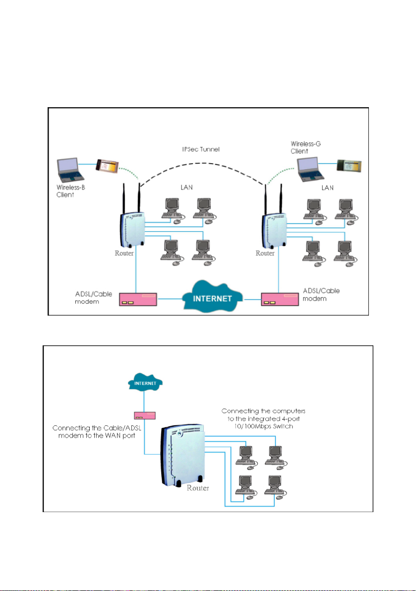
multiple IPSec tunnels to remote locations,
thus promoting increased scalability within a
robust security infrastructure.
This highperformance
router also bears
Quickly access your
network device’s Web
administration setup with
Have you heard of
If not, keep reading and
discover the ultimate
uConfig!
Parallel Broadband
Internet solution is
delivered!
?
1
Page 11

Chapter 2: Getting to know your Router
The following will help you get more acquainted with the rich suite of
features off e r e d by the router so tha t you are better a b le to e x p loit your
router’s full potential.
Key features
Compatible with IEEE 802.11g/b and IEEE 802.11a standards
Adopting the 802.11g standard, the router provides you the fastest wirel ess access within
your office or home network. Since it is fully backward compatible wi th 802.11b, you can
safeguard your existing network investments.
You can browse or uConfig to the web interface for e ffortles s configuration.
• HTTPS (SSL) is supported in addition to the standard HTTP. HTTP (SSL) features
• Telnet allows a computer to remotely connect to the CLI (Command Line
• SSH (Secure Shell Host) establishes a secure host connection to the CLI for
control and monitoring.
Easy Management & Configuration
Additionally, you can make use of these features:
additional authentication and encryption for secure communication.
Interface) for control and monitoring.
SSH is designed and created to provide the best
security when accessing another computer remotely. Not only does it
encrypt the session, it also provides better authenticatio n facilities and
features that increase the security of other protocols. It can use different
forms of encryption and ciphers.
• SNMP feature for managing the network performance.
2
Page 12

Virtual AP (Multiple SSID)
Virtual AP implements mSSID (Multi-SSID)
This allows a single wireless card to be set up with up to 16 virtual AP connections with
different SSIDs or BSSID (Basic Service Set Identifier) and security modes.
WMM
WMM (Wireless Multimedia) improves the user experience for audio, video, and voice
applications by prioritizing data traff ic.
Point-to-Point & Point-to-MultiPoint Support
Point-to-Point and Point-to-MultiPoint communication between different buildings enables
you to bridge wireless clients that are kilometres apart while unifying the networks .
Antenna Alignment
Antenna Alignment function finds the best alignment for the unit antenna by measuring the
quality of the signal.
3
Page 13

g
Security Features
You will be glad to learn about the security elements we have put in
place to better protect y our data and privacy.
WPA (Wi-Fi Protected Access) Standard & 802.1x Authentication
The router supports the WPA standard for enhanced security in your wireless ne twork.
The WPA protocol combines two mechanisms: Dynamic Key Encryption and Mutual
Authentication for enhanced security in the wireless LAN. This combination ens ures that
all users are authenticat ed through a central authority before being allowed network
WPA Modes:
• WPA Personal
• WPA Enterprise
• WPA2 Personal
• WPA2 Enterprise
• WPA Auto P ersonal
• WPA Auto Enterprise
Detailed informatio n on the WPA Modes can be found in Chapter 5: Settin
–
64/128-bit WEP encryption
The router supports the WEP (Wired Equivalent Privacy) protocol with key lengths of 64-bit
and 128-bit to protect data communication in your wireless network.
access.
Up A WLAN
4
Page 14

r
r
g
Additional Features
These features reveal the comprehensive range of advanced
functionalities when the router is further configured.
Static IP, Dynamic IP, PPPoE, PPTP, and L2TP WAN types
Whether you have subscribed to fixed IP, dynamic IP or PPPoE, you can use the router fo
broadband cable /ADSL Internet connection sharing.
Parallel Broadband
The unique Parallel Broadband technology features improved load balancing and fail-ove
Internet connectivity.
Built-in “NAT” firewall & Packet filtering
Since it handles the incoming and outgoing data packet transactions between your LA N
and the external network, the router can validate indivi dual packet information before
passin
it on to a LAN client. To complement NAT, you can use the packet filtering features
to regulate Internet access and control the transmission of TCP, UDP, ICMP or IGMP packets
to and from your LAN clients.
Virtual Servers based on Port-forwarding, IP-forwarding and DMZ’s
The router lets you set up Internet applic ation servers such as FTP file servers and HTTP web
servers based on Port-forwarding, IP-forwarding and Demilitar ised Zone hosts.
5
Page 15
When to use which router
NetPassage 18A IB11US, 1A13EU, IB11US, and 1B13EU are
dualband wireless A+G VPN Internet router offering
simultaneous support of IEEE 802.11a and IEEE 802.11g/b wireless
LAN connections.
NetPassage 18A 1A00US, 1A00EU, 18A 1B00US, and 1B00EU are
VPN Internet routers used only in wired environments.
6
Page 16
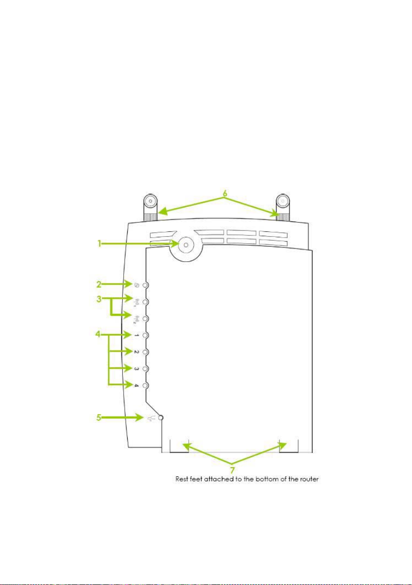
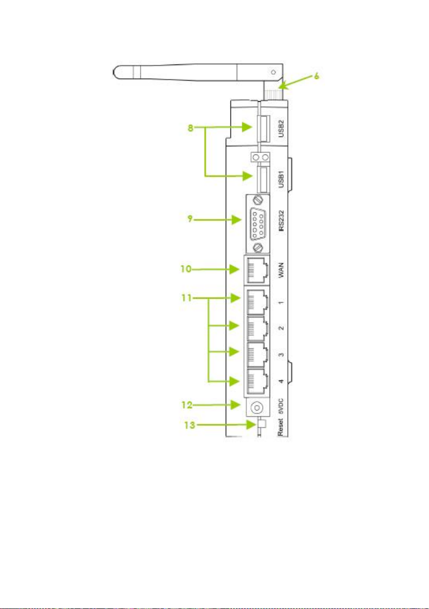
Panel Views
The router has been designed such that it can either be placed on a
desktop or mounted onto a wall.
LED indicators denoting network status and activity, are situated on the
front edge of the router for easy visibility. Moreover, two plastic feet
support the router in a standing arrangement, thus minimising desktop
clutter and ensuring better orga nization when setting up the hardware.
NOTICE: Actual product appearance may slightly differ depending
on the hardware version.
7
Page 17
8
Page 18

Panel Description
Name Description
1 Power (LED)
2 WAN (Link/Activi ty LED)
3 WLAN (1), (2)
(Link/Activi ty LED)
4 1, 2, 3, 4
(Link/Activity/Speed
LEDs)
5 DIAG (LED) This LED is reserved for diagnostic purposes.
Steady
Green
Off No power is supplied to the
Steady
Green
Flashing
Green
Steady
Green
Flashing
Green
These LEDs reflect the status of the integrated
Fast Ethernet Switch.
They will light up when connected with an
Ethernet cable.
Steady
Green
Flashing
Green
Steady
Amber
Flashing
Amber
The device is powered up.
device.
The WAN connection is ON.
Data transmission at WAN
connection.
Wireless interface up and
running.
Ready for operation.
Activity is detected in the wireless
network.
There is a connectivity link of
100Mbps.
100Mbps data transmission is
detected at the port
concerned.
There is a connectivity link of
10Mbps.
10Mbps data transmission is
detected at the port
concerned.
9
Page 19

6 External Antennas SMA antennas
7 Rest Feet These rest feet hold the router in the standing
position.
8 USB1, USB2 USB Ports
(NP18A 1A, NP18A 2A)
9 R232 (Integrated Serial
Interface)
These ports support printers, webcams, or
hard drives.
Not in use.
Reserved for future update.
10 WAN (Ethernet Port)
10/100Base-T Port connects to Cable/ADSL
modem.
11 1, 2, 3, 4 (Ethernet Ports) Integrated 3-port 10/100Mbps Switchi ng.
Ports 1, 2, 3, and 4 all function as normal
Ethernet ports except that Port 4 supports PoE
connection.
Connect Port 4 to PoE Injector if you wish to
use it to supply power to the unit.
12 DC Jack Direct Current jack.
If using power adapter to supply power to the
unit, attach the power adapter to the main
electrical supply and connect the power plug
into the DC Jack of the router.
10
Page 20

13 Reset (Push Button)
NOTE:
Although the Ethernet ports are numbered 1 to 4, they DO NOT have
!
to be connected sequentially.
For example: in a network of two computers, you can choose to
connect one computer to Port 2 and another to Port 4.
The table below illustrates the use of the Reset
button.
Reset
Push
Button
Less than
3 sec
5 sec Fast Blinking Restores the
Between
8 sec and
10 sec
More
than 10
sec
Diagnostic
LED
Router
Behavior
On Reboots.
Slow Blinking Restores all the
Off Reset
default login
password,
which is
‘password’.
default factory
settings
including
password.
cancelled.
11
11
Page 21
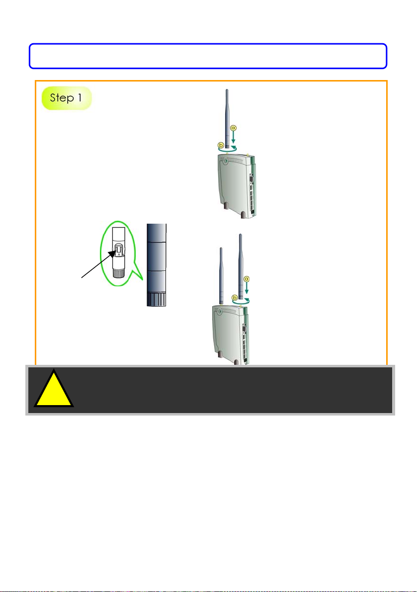
Chapter 3: Hardware Setup
Before attaching a pair of
external antennas to the router,
take note of the ‘A’ marking on
one of the two antennas.
The antenna with the ‘A’ marking
is the Dualband AG Antenna.
Connect the singleband G antenna to Ant2 on the RIGHT.
Connect the Dualband
AG antenna to Ant-1 on
the LEFT.
‘A’ marking
The antenna without the marking
is the single-band G Antenna.
!
Important: To ensure proper functionality of the router,
these two antennas MUST NOT be swapped.
12
Page 22
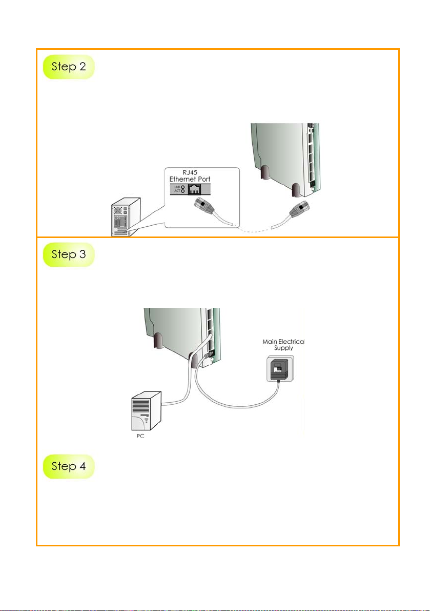
Insert one end of the RJ45 Ethernet cable to any of the LAN ports (1, 2,
3, or 4) on the router and the other end to your PC’s Ethernet network
adapter.
PC
Attach the power adapter to the main electrical supply and connect
the power plug into the socket of the router.
Power on your PC.
Notice that the Power and the corresponding port LEDs have lighted
up.
This indicates that connection has been established successfully
between the router and your PC.
13
Page 23

Chapter 4: Accessing the Web interface
This chapter consists of the following:
Overview of alternatives to access the web interface
How to uConfig to the web interface
How to browse to the web interface
Overview of alternatives
The router can be configured with the web interface.
After connecting the router to your PC, there are two methods of
accessing its web interface:
Installing and running the uConfig utility.
Changing your web browser settings.
How to uConfig to the Web Interface
The uConfig utility has been developed to allow access to the web
interface of your product without having to change the TCP/IP settings
of your PC.
Installing uConfig
1
Insert the Product CD into the CDROM drive.
It will automatically run and display
the web page.
exclusive!
2
1. Click on Utilities.
2. Select to install the uConfig utility on
your hard disk.
3. After installation, double-click on the
uConfig icon to run the program.
14
Page 24
After installation, your PC will automatically detect connected
products.
Double-click on the uConfig utility icon to run the program.
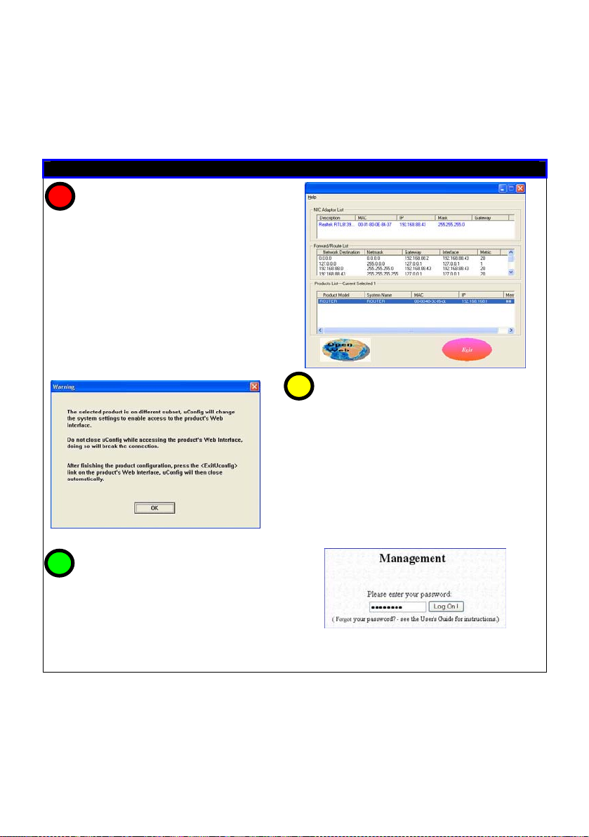
Running uConfig
1
1. Ensure that the router is selected
under the Products List.
2. Click on Open Web.
This opens the router’s login
screen.
3
At the authentication page, click on
the LOGIN! button to enter the main
configuration page.
Note: The default password is
“password”
2
This screen prompts you not to exit uConfig
while accessing the web interface or else
connection to the device will fail.
Click on the
OK button to proceed.
15
Page 25
g
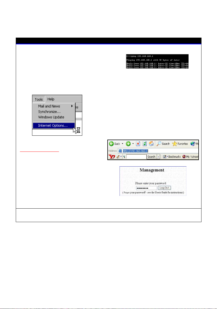
How to Browse to the Web Interface
Browsing to the web interface
Open your Command
window and type in: ping
192.168.168.1 to verify that your PC
can communicate with the router.
prompt
If your TCP/IP settings are
correct, you will
et replies to
this ping command.
1. At the address bar, type:
http://192.168.168.1
2. At the login page, press the
LOGIN! button to enter the
configuration pages.
Note: The default password is
“password”
You will then reach the home page of the router’s web interface.
1. Launch your web browser.
2. Under the Tools tab, select
Internet Options.
3. Open the Connections tab.
4. In the LAN Settings section, disable
all the option boxes.
16
Page 26

Chapter 5: Setting Up a WLAN
This chapter applies exclusively to Wireless Setup (a/b/g) and Wireless
Setup (b/g).
Wireless Setup (a/b/g) supports IEEE 802.11a and IEEE 802.11g/b wireless
LAN connections simultaneously.
Wireless Setup (b/g) supports IEEE 802.11b and IEEE 802.11g wireless LAN
connections simultaneously.
Whether you’re a home user or a network administrator, a WLAN
implementation will allow your roaming users to enjoy network
resources anywhere, anytime. It also provides convenience, and cost
savings, since deploying WLANs is less costly than setting up cables.
The next sections involve the following:
WLAN Setup
Wireless Security Settings
Advanced Settings
The steps featured are common to both Wireless Setup (a/b/g) and
Wireless Setup (b/g), unless otherwise stated.
17
Page 27
Operation Modes
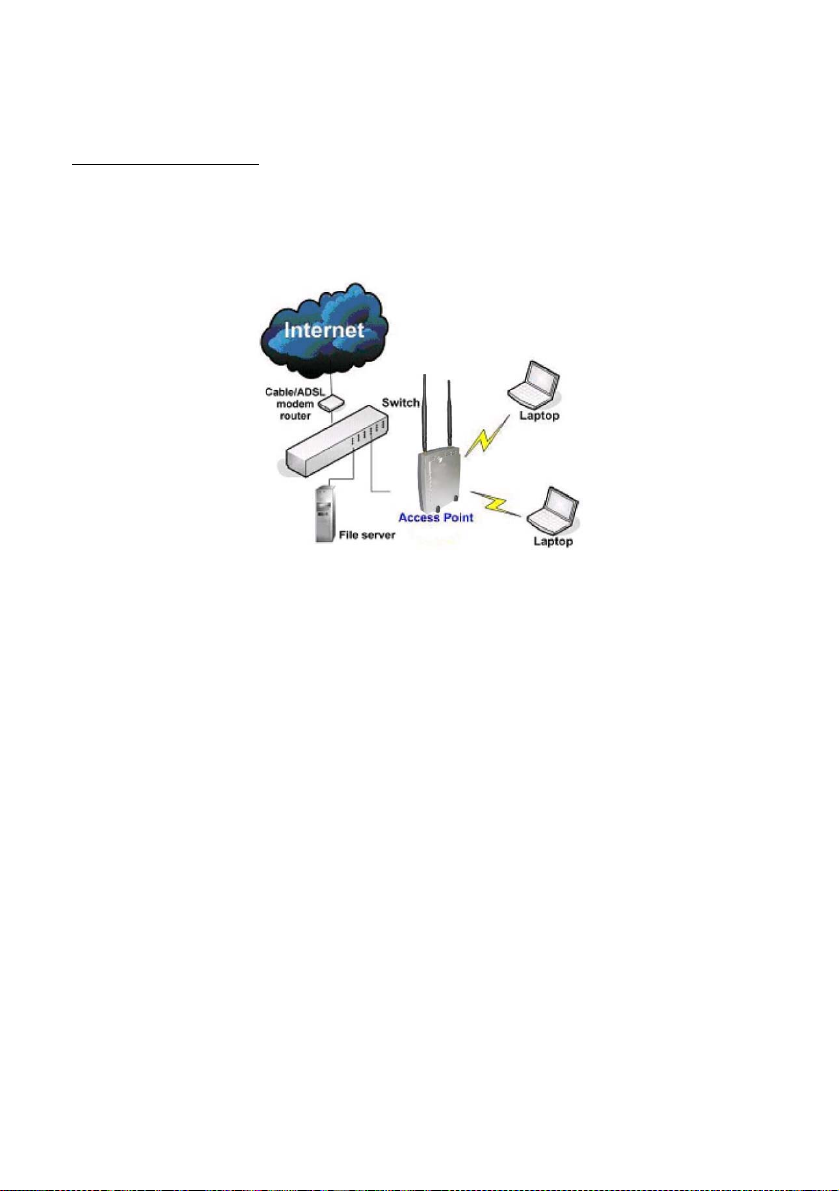
Access Point Mode
This is the default mode of your access point. The Access Point mode
enables you to bridge wireless clients to access the wired network
infrastructure and to communicate with each other.
In the example above, the wireless users will be able to access the file
server connected to the switch through the access point in Access
Point mode.
18
Page 28
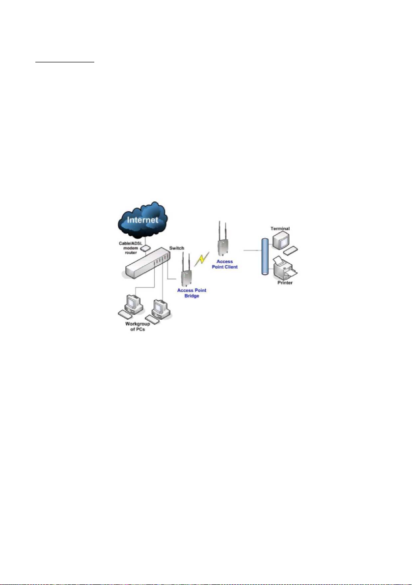
Client Mode
In Client mode, the device acts as a wireless Client.
When connected to an access point, it will create a network link
between the Ethernet network connected at this Client device, and
the wireless and Ethernet network connected at the access point.
In this mode it can only connect with an access point. Other wireless
clients cannot connect with it directly unless connected to the same
access point - allowing them to communicate with all devices
connected at the Ethernet port.
In the example above, the workgroup PCs will be able to access the
printer connected to the access point in Access Point Client mode.
19
Page 29
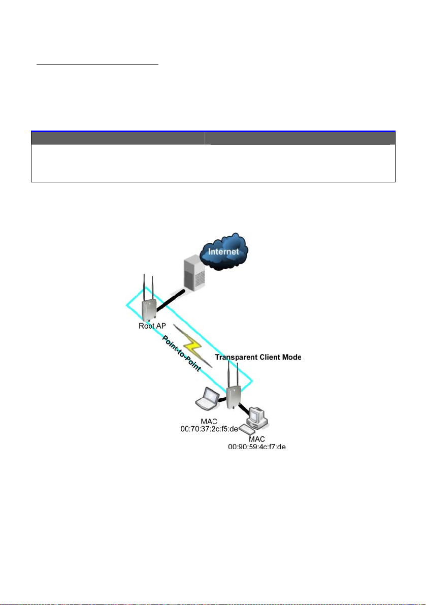
Transparent Client Mode
In Transparent Client Mode, the access point provides connection with
an AP acting as Root AP. This operation mode is designed for
implementation of Po int-to-Point and Point-to-MultiPoint connection s.
Point-to-Point
An access point acts as Root AP
and 1 other access point acts as
Transparent Client.
An access point acts as Root AP
and several other access point acts
Point-to-MultiPoint
as Transparent Clients.
This mode is generally used for outdoor connections over long
distances, or for indoor connections between local networks.
20
Page 30
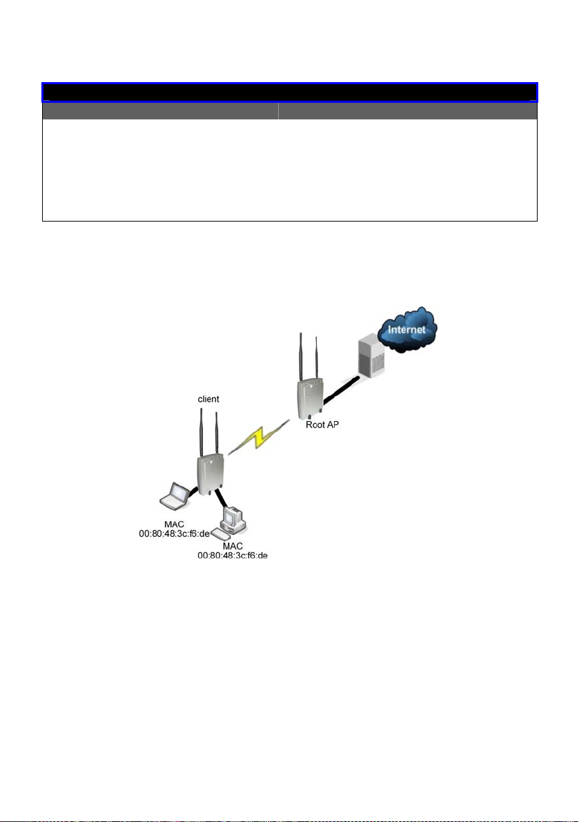
Difference Between other client modes and Transparent Client Mode
Other client modes
Connectivity with any standard
APs.
All devices connected to the
Ethernet ports use a common
MAC address for
communications with the AP.
Transparent Client Mode
Connectivity with RootAP-supported
APs.
Devices connected to the Ethernet
ports flow through freely and
transparen tly without the MAC
address restriction.
Transparent Client Mode is more transparent, making it more suitable for
linking two networks as point-to-point, or point-to-multi-point network
connection.
21
Page 31

To Set Up a Wireless LAN
Follow these steps to setup your wireless LAN for IEEE 802.11a, IEEE
802.11b, and IEEE 802.11g.
WLAN Setup (a/b/g)
1
Click on WLAN Setup(a/b/g) from
the CONFIGURATION menu.
2
Select Basic to make changes.
If you disable the card, you will not be
able to use the features of this wireless
card.
If you wish to disable the card, click on
the Click to Disable This Wireless Card
button.
Click Reboot in Reboot System page.
Rebooting
reboots.
The Wireless Card Disabled screen
indicates that the wireless card has
been disabled.
page displays and machine
22
Page 32

3
The router supports wireless LAN
connectivity that is fully compliant
with the IEEE 802.11g, IEEE 802.11a,
and IEEE 802.11b standards.
It also employs different security
modes to secure the data
transmission of the wireless clients
within your network.
The Current Mode
Access Point.
To change the mode, click on the
Change button.
To change the wireless mode,
4
make a selection from the dropdown box.
is defaulted to
Operation Mode : The router supports three types of modes such as Access
Point, Client, and Transparent Client.
WLAN name (ESSID) : Enter a preferred name for the wireless network.
Your wireless clients must be configured with the same ESSID
(sometimes referred to as SSID).
23
Page 33

Wireless mode
Country Code : Choose the Country where you are located.
Channel : This option allows you to select a frequency channel for
Tx Rate : Allow you to choose the rate of data transmission from
Maximum Associations : Allow you to l im it the num ber of WLAN asso ciati ons tha t can
Closed system
Act as RootAP
VLANID
Select from the list of wireless modes available:
:
802.11a (not supported by WLAN Setup for b/g)
This mode supports wireless A clients with data rates of up to
54Mbps in the frequency range of 5.4GHz.
802.11b only
This mode supports wireless B clients with data rates of up to
11Mbps in the frequency range of 2.4Hz.
802.11g only
This mode supports wireless G clients with data rates of up to
54Mbps in the frequency range of 2.4Hz.
802.11b/g mixed
This mode supports both wireless B and G clients.
The basic rates are: 1, 2, 5.5, 11, 6, 9, 12, 18, 24, 36, 48, and
54Mbps.
wireless communication.
Select SmartSelect to automatically scan and recommend
the best channel that can be utilised.
1Mbps to Fully Auto.
be made from 1 to 128. Default: 32
The router will suppress and not broadcast its WLAN name
:
(SSID) when Closed system is enabled.
Closed system is disabled by default.
The router will connect with one or multiple Transparent
:
Clients to create a point-to-point and point-to multi-point
connections network with 2 or more APs.
This connection method is fully compliant with 802.1h
standards.
Select and specify the VLANID.
:
This is a number to identify the different virtual network
segments to which the network devices are grouped.
This can be any number from 1 to 4094.
24
Page 34

Point-to-Point & Point-to-MultiPoint Setup
You can implement Point-to-Point connection by simply setting one
access point as RootAP in Access Point mode and setting the other
access points to Transparent Client mode.
You can set a root access point and a transparent client to allow pointto-point communication between different buildings and enable you to
bridge wireless clients that are kilometres apart while unifying the
networks. Or you can set a root access point and multiple transparent
clients to allow point-to-multiple-point communication betw een the
access point located at a facility and several other access points
installed in any direction from that facility.
Follow these steps to setup RootAP
RRoooottAAPP SStteepp 11::
Click on WWLLAANN SSeettuupp from the CCOONNFFIIGGUURRAATTIIOONN menu. You will see
the sub-menus expanded under WWLLAANN SSeettuupp. Click on BBaassiicc.
Ensure that TThhee CCuurr
reenntt MMooddee is set to AAcccceessss PPooiinntt.
r
To change TThhee CCuurrrreenntt MMooddee, please refer to: Common
Configuration – WLAN Setup - To Configure the Basic Setup of the
Wireless Mode.
25
Page 35

RRoooottAAPP SStteepp 22::
Select AAcctt aass RRoooottAAPP, click on the AAppppllyy button and reboot your
device to let your changes take effect.
26
Page 36

Follow these steps to setup Transparent Client/s.
TTrraannssppaarreenntt CClliieenntt SStteepp 11::
Click on WWLLAANN SSeettuupp from the CCOONNFFIIGGUURRAATTIIOONN menu. You will see
the sub-menus expanded under WWLLAANN SSeettuupp. Click on BBaassiicc.
Ensure that TThhee CCuurr
reenntt MMooddee is set to TTrraannssppaarreenntt CClliieenntt.
r
To change TThhee CCuurrrreenntt MMooddee, please refer to: Common
Configuration – WLAN Setup - To Configure the Basic Setup of the
Wireless Mode.
27
Page 37

TTrraannssppaarreenntt CClliieenntt SStteepp 22::
Select the RReemmoottee AAPP MMAACC checkbox.
Enter the RReemmoottee AAPP MMAACC.
Note:
When using RReemmoottee AAPP MMAACC, the EESSSSIIDD name must also match the
AP’s ESSID name, especially when Closed System is enabled on the
AP.
Repeat Transparent Client step to a dd more points to the Point-toMultiPoint connection.
28
Page 38

How to Make Your WLAN More Secure
All your network clients MUST share the same wireless settings as your
router to be able to communicate.
The router offers 8 types of security modes:
WEP
Short for Wired Equivalent Privacy, WEP is a security protocol basing on
a secret key to encrypt data packets before they are transmitted.
You MUST
router as well as to all your wireless clients.
802.1x
This mode conforms to the IEEE 802.1x authentication standard that
ensures that a client is not given access to net work resources unless it
has been successfully authenticated.
There MUST
function.
WPA Personal
WPA, or Wi-Fi Protected Access, is a protocol for authorising and
authenticating users onto the wireless network and implements the
majority of the IEEE 802.11i standard.
WPA Personal mode implements a shared network password for clients
and access points.
The only interaction is between the router and the client, therefore, a
RADIUS server is NOT
WPA Enterprise
WPA Enterprise mode implements the 802.1X authentication.
There MUST
function.
remember to apply the same WEP settings and key to the
be a RADIUS server on your LAN for this security mode to
required.
be a RADIUS server on your LAN for this security mode to
29
Page 39

WPA2 Personal
WPA2 Personal mode implements the full IEEE 802.11i standard with a
shared network password for clients and access points.
The only interaction is between the router and the client, therefore, a
RADIUS server is NOT
required.
WPA2 Enterprise
WPA2 Enterprise mode implements the full IEEE 802.11i standard and
802.1X authentication.
There MUST
be a RADIUS server on your LAN for this security mode to
function.
WPA Auto Personal
WPA Auto Personal mode implements a shared network password for
clients and access points and if there are no WPA enabled access
points available with the given SSID in WPA Personal mode, the unit will
attempt to associate with a non-WPA point with the given SSID, if
available.
The only interaction is between the router and the client, therefore, a
RADIUS server is NOT
required.
WPA Auto Enterprise
WPA Auto Enterprise implements 802.1X authentication and if there are
no WPA enabled access points available with the given SSID in WPA
Enterprise mode, the unit will attempt to associate with a non-WPA
point with the given SSID, if availa ble.
There MUST
be a RADIUS server on your LAN for this security mode to
function.
30
Page 40

The subsequent sections illustrate how to configure each security
mode.
Begin with following the two common preliminary steps shown below to
select the most appropriate security mode to protect your wireless
communications.
Selecting a security mode
1
Click on WLAN Setup(a/b/g) from
the CONFIGURATION menu.
Select Security.
1. Make a selection from the
2
Security Mode drop down menu.
The Security Mode is disabled by
default.
2. Click on Apply.
31
Page 41

How to Setup WEP
WEP
You can define up to 4 WEP
1
keys.
For each key, you can specify:
The Key Entry Method, by
selecting either:
- Hexadecimal
- ASCII text
The encryption level, from
the dropdown list:
- 64-bit
- 128-bit
Click Edit to set the keys, and
then click Apply.
32
Page 42

T
hex
hex
For hexadecimal key entry:
2
1. Select the Hex radio button.
2. Select the radio button of
the key to be entered.
3. Select the key encryption
mode from the drop down
menu.
4. Fill in the key value.
A hexadecimal value is made of
digits 0-9 and letters A-F,
case-sensitive.
For 64-bit encryption:
Your WEP key has to be 10
digits long.
For 128-bit encryption:
Your WEP key has to be 26
digits long.
5. Click on Apply.
6. If the key format is valid, the
page will refresh and the
key will appear in encrypted
form.
and is NO
33
Page 43

r
4
3
For ASCII key entry:
1. Select the ASCII radio
button.
2. Select the radio button
of the key to be
entered.
3. Select the key
encryption mode from
the drop down menu.
4. Fill in the key value.
An ASCII value can take in any
alphanumeric character and is
NOT case-sensitive.
For 64-bit encryption:
Your WEP key has to be 5
characters long.
For 128-bit encryption:
Your WEP key has to be 13
characters long.
5. Click on Save.
6. If the key format is valid,
the page will refresh
and the key will appea
in encrypted form.
To add more hexadecimal WEP keys,
repeat step 2.
To add more ASCII WEP keys, repeat
step 2.
You can set a maximum of 4 WEP keys
using different key entry methods and
encryption levels.
To specify which key to use:
1. Select the radio button of
the key to be used.
2. Click on Apply, then on
Reboot
changes.
to apply the
34
Page 44

t
y
How to Setup 802.1x
802.1x
1. Key in the IP address of
1
the Primary RADIUS Server in
your WLAN.
Optional: You may also key in a
Secondary RADIUS Server, if
any.
Note: The RADIUS server MUST
in the same subnet as your router.
2. The Authentication Port is
preset as 1812, but another port
number can be used.
Note: The Authentication Port
match the corresponding
MUST
port of the RADIUS server.
3. Enter the Shared Secre
Key, known only to you and the
RADIUS server.
4. The Accounting Port
preset as 1813, but another port
number can be used.
5. You can opt for a Ke
Length of either 64 bits (10 hex /
5 ASCII values) or 128 bits
hex / 13 ASCII values).
6. Click on Apply.
7. Click on Reboot to restart
the system, after which the
settings will be effective.
be
(26
is
35
Page 45

r
r
r
How to Setup WPA Enterprise Modes
Follow these steps to setup the router to use WPA Enterprise, WPA2
Enterprise, and WPA Auto Enterprise.
WPA Enterprise
1
1. Select the Cipher Type to
implement:
• TKIP
• AES
• AUTO
The Cipher Type is set to
AUTO by default
router can automatically
detect which cipher type
can be supported by the
client.
2. Key in the IP address of the
RADIUS Server in your WLAN.
Note: The RADIUS server MUST
in the same subnet as you
router.
3. The Authentication Port is
preset as 1812, but anothe
port number can be used.
Note: The Authentication Port
match the corresponding
MUST
port of the RADIUS server.
4. Enter the Shared Secret Key,
known only to you and the
RADIUS server.
5. The Accounting Port is preset
as 1813, but another port
number can be used.
so that the
be
6. Click Apply.
7. Click on Reboot to restart
the system, after which you
settings will become
effective.
36
Page 46

How to Setup WPA Personal
Follow these steps to setup the router for using WPA Personal, WPA2
Personal, and WPA Auto Personal.
WPA Personal
1
1. Fill in the Passphrase or pre-
shared network key.
2. Select the Cipher Type to
implement:
a. TKIP
b. AES
c. AUTO.
The Cipher Type is set to
AUTO by default
router can automatically
detect which cipher type
can be supported by the
client.
so that the
1. Click Apply.
2
2. Click Reboot to restart the
system, after which your settings
will become effective.
37
Page 47

Advanced WLAN Settings
Follow these steps to change the radio settings of your router.
Editing Advanced Settings
1
1. Click on WLAN Setup
(a/b/g) from the
CONFIGURATION menu.
2. Select Advanced.
2
1. Set the Beacon Interval (the ti me laps e
between every beacon sent) to any
value between 200 and 1000.
It is preset as 200 seconds.
2. Set the Data Beacon Rate
16384.
This determines how often the beacon
should contain a Delivery Traffic
Indication Message (DTIM) that tells
power-save clients that a packet is
waiting for them.
3. Set the RTS/CTS Threshold from 256 to
2346.
It is preset to 2346.
4. Set the Frag Threshold from 256 to 2346.
It is preset to 2346.
5. Transmission Power Control (TPC) offers
the flexibility to set the Transmit Power.
(802.11h compliant)
It is set to Maximum by default, but
should be reduced if there is more than
one unit using the same channel
frequency.
It can be set from Minimum to
Maximum, 1dBm to 20dBm, in
increments or 1dBm per step.
from 1 to
38
Page 48

r
r
1. Click Apply.
3
Changes will be enabled afte
reboot.
6. Select whether to enable Station
Isolation.
This security feature implements
isolation, in order to prevent
network clients from attacking
other network clients.
8. Dynamic Frequency Selection
7. The Antenna Control
allow you to control whether to
use the:
• MAIN antenna (Default)
• AUX (Auxiliary) antenna
OR
• Diversity, to monitor the
signal from each antenna
and automatically switch to
the one with the bette
signal.
For Antenna Control
recommended settings, please
refer to the next section.
(DFS) support provides flexible
selection of the best frequency
channel for the wireless
communication to allow mobility
among networks.
It reduces interference by
detecting and avoiding other
frequencies in use.
(DFS is a component of, and
compliant with 802.11h
specifications.)
DFS is enabled by default.
function
39
Page 49

Antenna Control
These are the recommended antenna control settings.
Antenna Control
If both antennas are
connected: set antenna
control to Diversity
If antenna is connected to
auxiliary: set antenna control
to AUX
If antenna is connected to main: set
antenna control to MAIN
40
Page 50

Long Distance Parameters
It is necessary to adjust the long distance parameters, only if the
distance is 100 meters and beyond.
Follow these steps to change the long distance parameters of your
router.
Editing Long Distance Parameters
1
1. Click on WLAN Setup
(a/b/g) from the
CONFIGURATION menu.
2. Select Advanced.
1. Click Long Distance Parameters.
2
41
Page 51

3
1. Select whether to
Enable or Disable
Outdoor operation.
2. Enter Distance of the
unit in meters.
3. Enter the SlotTime.
4. Enter the
acknowledgement
timeout.
5. Enter the CTS timeout.
6. Click Apply.
To view recommended long
distance parameters:
Click Show Reference Data
button.
This dialog box displays if the Distance
entered is less than 100 meters.
42
Page 52

WMM
Wireless Multimedia (WMM) is a feature specially developed to improve
the user’s experience for audio, video, and voice applications by
prioritizing data traffic.
43
Page 53

3
Follow these steps to change the setup Wireless Multimedia on your
access point.
Setting WMM
1
3. Click on WLAN Setup
4. Select Advanced.
(a/b/g) from the
CONFIGURATION menu.
Click WMM Settings.
2
1. Select to Enable Wireless
Multimedia (WMM)
2. Enter the desired WMM parameters.
Using the default parameters is
recommended.
3. Click Apply to apply the WMM
settings, click Default to reset all
parameters to def ault, or click Back
to discard any changes and return
to WLAN Basic Setup page.
44
Page 54

WMM Parameters (for advanced users)
AIFs (Arbitrary Inter-
Frame Space)
Cwmin (Contention
Window Minimum)
CwMax (Contention
Window Maximum)
TxOp limit (Transmit
Opportunity Limit)
NoAck (No
Acknowledgement)
ACM (Admission
Control Mandatory)
BE (Best Effort)
BK (Background)
VI (Video)
VO (Voice) Parameters for voice data traffic.
Arbitrary I nter-Frame Space is the fixed wait ti me for different
data traffic to access the network.
Contention Window Minimum is the minimum random wait time
for different data traffic to access the network.
Contention Window Maximum is the maximum random wait time
for different data traffic to access the network.
Transmit Opportunity limit specifies the duration that an end-user
device can transmit data traffic. TxOp limit can be used to give
data traffic lo nger and shorter access.
No Acknowledgement provides control of the reliability of traffic
flow. Usually an acknowledge packet is returned for every
packet received, increasing traffic load and decreasing
performance.
Enabling No Acknowledgement cancels the acknowledgement.
This is useful for data traffic where speed of transmission is
important.
Admission Control Mandatory enables WMM on the radio
interface. When ACM is enabled, associated clients must
complete the WMM admission control procedure before access.
Parameters for Data0 Best Effort.
Best Effort data traffic has no prioritization and applications
equally share available bandwidth.
Parameters for Data1 Background.
Background data traffic is de-prioritized and is mostly for backup
applications, or background transfers like backup applications or
background transfers like bulk copies that do not impact
ongoing traffic like Internet downloads.
Parameters for video data traffic.
45
Page 55

Statistics
Follow these steps to view the WLAN detailed connections statistics per
WLAN station.
Statistics
1
1. Click on WLAN Setup (a/b/g)
from the CONFIGURATION
menu.
2. Select Statistics.
3
The WLAN connection’s statistics
displays.
Click Back to return to WLAN Basic
Setup page.
2
1. Select the WLAN connection to view
statistics of.
• Click Refresh to refresh the WLAN
Connection List.
• Click Back to return to the WLAN
Basic Setup page.
46
Page 56

Virtual AP (Multiple SSID)
Virtual AP implements mSSID (Multi-SSID) whereby a single wireless card
can be setup with up to 16 virtual AP connect ions wit h different SSI Ds or
BSSID (Basic Service Set Identifier) and security modes.
Virtual AP delivers multiple services by VLAN segmentation: making the
network think there are many SSIDs available and channeling each
connection through different VLANs to the respective virtual network
segments on the Ethernet network.
How it Works
When WLAN PC 1 connects to VAP 1 its packets are channeled to
VLAN 10 group where only services connected to Port 2 and Port 3 are
available to this wireless connection.
It is similar for WLAN PC 2 and WLAN PC 3. Although they connect to
the same radio card as WLAN PC 1, WLAN PC 2 can only access the
services available at Port 6 and Port 7 and WLAN PC 3 can only access
the services available at Port 10 and Port 11.Follow these steps to setup
Virtual AP.
47
Page 57

3
Follow these steps to setup Virtual AP.
Virtual AP
1
1. Click on WLAN Setup (a/b/g) from the
CONFIGURATION menu.
2. Select Virtual AP.
2
Virtual AP List page displays.
• Click Apply to register changes.
• Click Clear to clear Virtual AP List.
• Click Back to return to WLAN Basic
Setup page.
• Select the Delete option beside
any Virtual APs you wish to delete.
Click Add to goto add Virtual AP page.
1. Enter ESSID name.
2. Settings:
• VLAN ID
• Closed System
• RootAP
3. Select Security Mode
4. Click Apply to make
changes or click Back to
return to Virtual AP List
page.
48
Page 58

Preferred APs (Only available in Client Mode)
When there is more than one AP with the same SSID, the Preferred APs
function allows you define the MAC address of the APs in order of
preference.
The MAC address at the top of the Preferred APs list has the highest
connection preference, and the MAC address at the bottom has the
lowest connection preference.
Follow these steps to specify your preferred APs.
Preferred APs
1
1. Click on WLAN Setup (a/b/g) from the
CONFIGURATION menu.
2. Select Preferred APs.
2
1. Enter the MAC addr esses of the
preferred APs.
2. Click Apply to effect the
settings.
49
Page 59

Antenna Alignment
The antenna alignment function helps you find the best alignment for
the antenna by measuring the quality of the signal.
For best results during the antenna alignment, turn off all wireless
networking devices within range except the device with which you are
trying to align the antenna.
Follow these steps to setup your wireless LAN.
Antenna Alignment
1
1. Click on WLAN Setup (a/b/g) from
the CONFIGURATION menu.
2. Select Antenna Alignment.
2
1. Enter the Remote AP MAC Address you
wish to align with.
2. Click Start to p erform antenna alignment.
NOTE: To ensure proper functionality of the device,
!
select to Stop after performing antenna alignment.
Alternatively, you may also reboot the device.
50
Page 60

p
Chapter 6: Configuration
This chapter describes the different featu res of your router and explains
how to customise them to meet your network requirements.
Setting up the router in your LAN
SNMP (Simple Network Management Protocol) Setup
Setting Up the Router in Your LAN
The following table lists out the parameters relevant to your LAN setup.
You can replace the default settings with appropriate values to suit the
needs of your LAN.
LAN Parameters Description
IP Address
Network Mask
Management
Gateway IP
The next two fields (DHCP Start IP Address and DHCP End IP Address) allow you
to define the range of IP addresses from which the DHCP Server can assign an
IP address to the LAN.
DHCP Start IP
Address
The IP address of your router access point is 192.168.168.1
by default.
When the DHCP server of the access point is enabled, this
LAN <IP address> would be allocated as the Default
Gateway of the DHCP client unless you set a different
<DHCP Gateway IP address>
The Network Mask identifies the subnet in which your
router resides.
The default network mask is 255.255.255.0.
(Optional) As a bridge router, the router does not usually
communicate with devices on other IP subnets. However,
the Management Gateway here acts as the equivalent
of the Default Gateway of a PC, to allow the router to
communicate with devices on different subnets.
For instance, if you want to access the router from the
internet or from the router on the LAN, you can set the IP
address of the router as the Management Gateway IP.
The Management Gateway IP address of your router is set
to Nil by default.
This is the first I P address that the DHCP server will assign.
The value you enter should belong to the same subnet as
your router.
For example if the IP address and network mask of your
router are 192.168.168.1 and 255.255.255.0 res
ectively,
51
Page 61

DHCP End IP
Address
DHCP Gateway IP
Address
Always use these
DNS servers
Primary DNS IP
Address
Secondary DNS IP
Address
DHCP Server
the DHCP Start IP Address should be 192.168.168.X where
X is any value from 2 to 254.
It is preset to 192.168.168.100.
This is the last IP address that the DHCP server can assign.
The value you enter should also belong to the same
subnet as your router.
For example if the IP address and network mask of your
router are 192.168.168.1 and 255.255.255.0 respectively,
the DHCP End IP Address should be 192.168.168.X where X
is any value from 2 to 254.
It is preset as 192.168.168.254.
Enter the IP address of the gateway to Internet or of the
router if this access point is the one connecting to the
Internet.
If your network uses multiple gateways / access points,
you may wish the router to act as DHCP server to a LAN
segment while another access point connects to the
Internet or to another LAN.
Though the DHCP server usually acts as the Default
Gateway of the DHCP client, you can define a different
<DHCP Gateway IP addr ess>, whi ch will be all ocated a s
the Default Gateway of the DHCP client.
The DHCP client will thus receive its dynamic IP address
from the router but will access the Internet or the other
LAN through the Default Gateway defined by the <DHCP
Gateway IP address>.
Enable this option if you want the router to use only the
DNS server you have specified.
Your ISP usually provid es the IP address of the DNS server.
This optional field i s for the IP address of a secondary DNS
server.
If DHCP server is disabled you will need to manually
configure the TCP/IP parameters of each computer in
your LAN.
52
Page 62

Setting Up Your LAN
Follow these steps to change the values and customise them for your
LAN settings.
LAN Setup
Click LAN Setup from the
1
CONFIGURATION menu.
2. Amend the relevant fields in the
2
LAN Setup page.
3. Click Apply, to apply the
changes.
53
Page 63

r
To view the active DHCP leases
The following will guide you to a display of the active IP address leases
that have been allocated by the built-in DHCP server.
To view the active DHCP leases
1. Click LAN Setup from the
1
CONFIGURATION menu.
2. In LAN Setup page, go to
Advanced DHCP Serve
Options.
3. Click Show Active DHCP
leases.
NOTE: Invalid date and time displayed in the Expires column
indicates that the clock of your router has not been set. Please
!
The DHCP Active Leases table displays:
2
The IP Address that has been
allocated to the DHCP client.
The Host Name of the DHCP
client.
The Hardware Address (MAC) of
the DHCP client.
The date and time when the I P
address leased expires.
refer to the SYSTEM TOOLS section for more details on how to
set the router’s clock.
54
Page 64

r
r
To reserve specific IP addresses for predetermined DHCP clients
The ability to make IP reservations enables you to assign a fixed IP
address to a predetermined client (identified by its MAC address), thus
informing the DHCP server to exclude that specific address from the
pool of free IP addresses it draws on for its dynamic address allocation.
For instance, if you set up a publicly accessible FTP/HTTP server within
your private LAN, while that server would require a fixed IP address, you
would still want the DHCP server to dynamically allocate IP addresses to
the rest of the PCs on the LAN.
The following shows you how to modify the settings of the built-in DHCP
server.
Advanced DHCP Options
1. Click LAN Setup from the
1
CONFIGURATION menu.
2. In LAN Setup page, go to
Advanced DHCP Serve
Options.
3. Click DHCP Serve
Reservations.
1. Enter:
2
The host portion of the IP Address
to reserve.
The Hardware Address, in 6 pairs
of two hex values
2. Click Add effect the changes.
3. The DHCP Reservations table will
refresh to display the currently
reserved IP addresses.
55
Page 65

3
If you do not need the DHCP
server to reserve an IP address
anymore, you can delete the
DHCP Server Reservation:
1. Select the reserved IP
address to delete.
2. Click Delete.
3. The DHCP Reservations
table will refresh to
reflect the changes.
56
Page 66

Bandwidth Control for WAN
Bandwidth Control allows you to decide the available bandwidth in
levels of 1kbit.
Follow these steps to setup Bandwidth Control for WAN.
Bandwidth Control for WAN
1
Click Bandwidth Control from the
CONFIGURATION menu.
3
To apply Bandwidth Control on WAN, in WAN
Bandwidth Control Setup:
1. Enter the Download Total Rate in kbit. This
restricts the bandwidth available for
downloading.
2. Enter the Upload Total Rate in kbit. This
restricts the bandwidth available for
uploading.
3. Click Apply.
2
Select whether to Enable or
Disable Bandwidth Control
and click Apply.
57
Page 67

Bandwidth Control for LAN
Bandwidth Control allows you to decide the available bandwidth in
levels of 1kbit.
Follow these steps to setup Bandwidth Control for LAN.
Bandwidth Control for LAN
1
Click Bandwidth Control from the
CONFIGURATION menu.
2
Select whether to Enable or
Disable Bandwidth Control
and click Apply.
3
Click Add to add a Bandwidth
Control Entry
58
Page 68

3
1. Enter the Bandwidth Control Rule
Name.
2. Enter the Committed R ate in kbit.
This sets the bandwid th committed.
3. Enter the Ceil Rate in kbit. This is
the ceiling rate whic h sets the
maximum bandwidth allowed.
4. Enter the Rule Type
Rule Types:
• Download by IP Address
• Download by MAC Address
• Upload by IP Address
• Upload by MAC Address
5. Enter the IP or MAC Address
according to the Rule Type
selected.
6. Click Add to add this Bandwidth
Control Entry or click Cancel to
cancel to disregard your entry.
59
Page 69

STP Setup
Spanning Tree Protocol is a link management protocol that provides path
redundancy while preventing undesirable loops i n the network. For an Ethernet
network to function properly, only one active path can exist between two
stations.
Multiple active paths between stations cause loops in the network. If a loop
exists in the network topology, the potential exis ts for duplication of messages.
When loops occur, some switches see stations appear on both sides of the
switch. This condition confuses the forwarding algori thm and results in dupl icate
frames being forwarded.
Enabling Spanning Tree Protocol
1
Click STP Setup from the CONFIGURATION
menu.
2
Select Enable, and click Apply to allow
spanning tree protocol to be activated
on the router.
STP Status:
Spanning Tree Protocol (STP)
function makes your network more
resilient to link failure and avoids
loop formation.
60
Page 70

Priority:
Specify the prior ity given to the AP.
This value determines which access point acts as the central reference point, or Root
AP, for the STP system — the lower the prio rity val ue, the more li kely the access point is
to become the Root AP.
If the priority val ues are all the same, then the system will search for the access point
with the smallest MAC address and set it as the Root AP.
Hello Time:
Specify the time in seconds that elapses between the generation of configuration
messages (also known as Hello BPDUs) by an AP that assumes itself that it’s the Root
AP.
Forwarding Delay:
Specify the time in seconds an AP spends in the listening and learning states (listening
for configuration messages.)
Max Aging Time:
Specify the maximum age in seconds of stored configuration message information,
after which it is judged as too old and are discarded.
Note: If an AP does not receive another configuration message after the Max Aging
Time, the system assumes that the link between itself and the Root AP has gone down
and reconfigures the network accordingly.
After specifying the values, click Apply to apply changes.
61
Page 71

SNMP Setup
SNMP (Simple Network Management Protocol) is a set of protocols that
facilitates th e e xc h an ge o f m an ag e men t i nf o rm ati o n b etw een ne two r k
devices. It enables network administrators to manage network
performance, detect and solve network problems, and plan for
network growth.
Follow these steps to setup SNMP.
SNMP Setup
Click SNMP Setup from the
1
System Tools menu.
3. From the SNMP drop-down list,
2
select Enable.
Read Password is set to public
and Read/Write Password
to private by default.
4. Enter the SNMP EngineID.
5. Press Apply.
6. Click Reboot.
You are recommended to change
to a different password.
set
62
Page 72

SNMP Trap
The SNMP Trap provides notification of significant network events
through unsolicited SNMP messages. This results in substantial savings of
network resources by eliminating the need for unnecessary SNMP
requests.
Follow these steps to setup SNMP Trap.
SNMP Trap
Click SNMP Setup from the
1
CONFIGURATION menu.
2
1. Select whether to Enable
or Disable the SNMP Trap.
2. Enter the Trap Destination
IP Address or Name.
This is the IP address of
the SNMP manager.
3. Enter the Community.
This is used to
authenticate messages
and is included in every
packet that is trans mitted
between the SNMP
manager and agent.
4. Click Apply.
63
Page 73

Chapter 7: Enabling and Disabling Router
This chapter describes the switching capability of the unit to operate
either as a router or access point.
Setting Up Router
By default, the unit is operating as a router.
The simple procedure to enable the router is described.
Enable Router
Click Enable Router from the
1
CONFIGURATION menu.
The Enable Router Function
2
appears. Click on the Enable
Router button.
64
Page 74

Setting Up Access Point
Follow these steps to disable the router and switch back as an access
point.
Disable Router
1
Click WAN Setup from the
CONFIGURATION menu.
Click Disable Router.
2
The Disable Router Function screen
3
appears. Click Disable Router again.
65
Page 75

Chapter 8: Router Setup
This chapter describes the different featu res of your unit when it is se t to
operate as a router.
Broadband Internet
Using NAT
Routing
Remote Management
Parallel Broadband
DDNS (Dynamic Domain Name System) Setup
Features unsuitable for office network:
Universal Plug and Play
DNS (Domain Name System) Redirection
!
Broadband Internet
Setting up the router in your network enables you to share a single cable or
ADSL Internet account among multiple LAN clients.
As the router supports several types of broadband Internet connections and
WAN protocols, you should verify your broadband Internet subscription type to
set up your router correctly.
NOTE: Universal Plug and Play and DNS Redirection
features are not designed for operation in an office
network.
To ensure proper functionality of the router, these
features should not be activated when connected to
an office network.
66
Page 76

WAN Setup
The configuration for each type of broadband I nternet connection is shown in
the following individual sections.
The system has to be restarted to effect changes in settings.
Start with these common steps to set the broadband connection type.
Changing the WAN Type
1
Click WAN Setup from the
CONFIGURATION menu.
The setup page of the WAN type last
implemented will be displayed.
As the router operates in Dynamic (DHCP)
Address Allocation mode by default,
initially the WAN Dynamic Setup page will
appear.
2
Clicking Change (which appears on the
setup pages of all the WAN Types),
displays the Select WAN Type page.
3
From Select WAN Type page, select the
WAN type to apply and click Apply.
The setup page of the selected WAN
type displays.
67
Page 77

Static IP
If you have subscribed to a specific IP address or t o a fixed range of IP
addresses from your ISP, follow these steps.
Static IP Configuration
1
Select Static IP Address from Select WAN
Type page and click Apply.
2
At the Static IP WAN Setup page:
1. Enter the IP Address, Network Mask, and
Gateway IP Address provided by your
ISP.
2. Click Apply.
3. Click Reboot System to restart the sy stem
and let the changes take effect.
68
Page 78

Dynamic IP
This is the default WAN Type of your router.
In this connection mode, your ISP will automatically assign its IP address.
This connection mode applies to most cable Internet subscribers, for
instance:
Singapore Cable Vision subscribers.
@HOME Cable Service users.
Follow these steps to setup Dynamic IP.
Dynamic IP Configuration
1
Select Dynamic IP Address as WAN
Type.
2
At Dynamic IP WAN Setup page:
1. You can review the:
- IP Address
- Network Mask
- Gateway IP Address
- Primary DNS
- Secondary DNS
The DHCP server of your ISP
dynamically allocates these
parameters.
Click Reboot System to allow the new
WAN type to take effect.
69
Page 79

PPPoE
Select this connection type if you hav e subscribed to ADSL in a country
utilising standard PPPoE for authentication, for instance:
If you are in Germany, which uses T-1 connection.
If you are a SingNet Broadband or Pacific Internet Broadband user
in Singapore.
These are the parameters in the PPPoE setup.
PPPoE Parameter Description
Username
Password
On-Demand
Idle Timeout
Always-On
Reconnect Time
Factor
This refers to your broadband account username.
This refers to your broadband account password.
If enabled, the router will automatically connect to the
ISP whenever a LAN client makes an Internet request.
This field is relevant only if On-Demand is enabled.
It allows you to specify an idle time allowed before the
router automatically goes offline.
It will only reconnect when a LAN client makes an Internet
request.
If the field is set to 0, this feature wil l be disabled, and the
router will remain online unless di sconnected by the ISP.
The default value is preset to 30 seconds.
If this feature is enabled, the router will remain
permanently connected to the Internet.
This field is relevant only if Always-On is enabled and
allows you to specify an offline time all owed, before the
router automatically reconnects to the Internet.
The default value is preset to 30 seconds.
70
Page 80

Follow these steps to setup PPPoE.
PPPoE Configuration
1
Select PPP over Ethernet from the Select WAN
Type menu.
2
At the PPPoE WAN Setup page:
1. Enter your broadband Internet account
parameters in the relevant fields.
2. The Status section displays your
connection settings such as:
IP Address
Network Mask
Gateway IP Address
Primary & Secondary DNS
3. If you are online, clicking Disconnect will
disconnect your connection.
4. Click Apply.
5. Click Reboot System button to res tart the
system and allow the WAN type
changes to take effect.
To use Email Notification, please refer to
Chapter 8: Router Setup – Broadband Internet
Through the router – WAN Setup Email
Notification
71
Page 81

PPTP
The Point-to-Point Tunneling Protocol (PPTP) enables the
implementation of secure multi-protocol Virtual Private Networks (VPNs)
through public networks, enabling secure remote access at lower cost.
Follow these steps to setup PPTP.
PPTP Configuration
To use Email Notification,
please refer to Chapter 8:
Router Setup – Broadband
Internet Through the router –
WAN Setup Email Notification
1
Select PPTP as your WAN Type at Select WAN
Type page.
2
At the PPTP WAN Setup page:
1. Select whether to enable DHCP.
2. Enter Client IP Address.
3. Enter Network Mask.
4. Enter the Gateway.
5. Enter the Username of your Internet
account.
6. Enter the Password of your Internet
account.
7. Enter the IP ad dress of your VPN Server.
8. Enter an Idle Timeout value between 30-
3600 seconds. Entering 0 will disable this
feature.
9. The Status section gives you a summary
of your connection settings such as:
• IP address
• Network Mask
• Gateway IP Address
10. If you are online, clicking Disconnect will
disconnect your connection.
11. Click Apply.
12. Click Reboot button to restart the sy stem
and allow the changes to take effect.
72
Page 82

L2TP
L2TP (Layer 2 Tunneling Protocol) is an extension to the PPP protocol
used for Virtual Private Networks (VPNs) that supports multiple protocols
and unregistered and privately administered IP addresses over the
Internet.
Follow these steps to setup L2TP
L2TP Configuration
1
Select L2TP as your WAN Type at Select WAN
Type page.
2
At the WAN L2TP Setup page:
1. Select whether to enable DHCP.
2. Enter Client IP Address.
3. Enter Network Mask.
4. Enter the Gateway.
5. Enter the Username of your Internet
account.
6. Enter the Password of your Internet
account.
7. Enter the IP ad dress of your VPN Server.
8. Enter an Idle Timeout value between 30-
3600 seconds. Entering 0 will disable this
feature.
9. The Status section gives you a summary
of your connection settings such as:
• IP address
• Network Mask
• Gateway IP Address
10. If you are online, clicking Disconnect will
disconnect your connection.
13. Click Apply.
14. Click Reboot button to restart the sy stem
and allow the changes to take effect.
73
Page 83

Email Notification
This feature notifies you by email if there is a change in the WAN IP
address.
Follow these steps to setup Email Notification.
Email Configuration
1
After applying WAN PPPoE Setup, WAN PPTP
Setup, or L2TP.
The WAN Setup screen of the WAN Type
displays. (PPPoE shown in this example.
Click Email Notification.
2
Click Enable and enter the following fields:
Email address of Receiver:
The email will be sent to this address.
IP address of Email Server:
This is the IP address of the SMTP server
through which the message would be
sent out.
Note: It is recommended to use your ISP’s
SMTP server).
User Name:
This is the email account user’s name
that should be entered if authentication
is required.
Password:
This is the email account user’s password
that should be entered if authentication
is required.
74
Page 84

Email address of Sender:
This is the email address that will appear
as the sender.
Needs Authentication specifies whether
the SMTP server requires authentication,
and is not selected by default.
Click Apply.
75
Page 85

Using NAT
NAT (Network Address Translation) functions by transforming the private
IP address of packets originating from hosts on your LAN so that they
appear to be coming from a single public IP address, and by restoring
the destination public IP address to the appropriate private IP address
for packets entering the private network. The multiple PCs on your LAN
would then appear as a single client to the WAN interface.
Enabling/Disabling NAT
NAT
1
Click NAT from the
CONFIGURATION menu.
NOTE: Disabling NAT will disable Internet Sharing.
!
Broadband Internet sharing requires this option to be
ENABLED
The NAT Status radio button is
2
enabled by default.
To change NAT Status:
1. Select the appropriate radio
button.
2. Click Apply.
.
76
Page 86

When NAT is enabled, your LAN is not accessible to the WAN. However,
implementing virtual servers allows you to host Internet servers such as
web servers, FTP servers or Mail servers on your LAN, in spite of NAT.
To Setup a De-Militarised Zone Host
If NAT is enabled, a request from the client within the private network
first goes to the access point. Upon receiving a request, the access
point keeps track of which client is using which port number. Any reply
from Internet goes to the access point first, the access point (from the
port number in the reply packe t) knows to which client to forward the
reply. If the access point does not recognize the port number, it will
discard the reply.
When using DMZ on a PC, any reply not recognized by the access point
will be forwarded to the DMZ-enabled PC instead.
You may wish to set up a DMZ host if you intend to use a specialpurpose Internet Service such as an online game for which no port
range information is available.
You can also host web pages or public information that can be serve d
to the outside world, on the DMZ host.
77
Page 87

DMZ
1
1. Click NAT from the
3
CONFIGURATION menu.
2. Ensure that NAT Status is set
to Enable.
At the Advanced NAT Options
section:
3. Click DMZ.
To disable DMZ:
3. In Private IP Address
field enter 0.0.0.0.
4. Click Apply.
1. In the Private IP Address field,
2
enter the IP address of the PC
you wish to place within the DMZ.
Private IP Address is set to 0.0.0.0
by default.
2. Click Apply.
!
NOTE:
1. The Static IP Address configuration is
recommended for the DMZ host when DMZ is
enabled, as the address may change if allocated
by DHCP, causing improper functioning of the
DMZ.
2. The DMZ host is not invulnerable to malicious
attacks from the Internet as DMZ exposes ALL of
the host’s ports.
Page 88

To Setup Port Forwarding
Port forwarding allows the router to redirect any incoming Internet
request bearing a public IP address to a specific PC on your LAN,
based on the incoming packet’s TCP/UDP port number.
Hence, using TCP port forwarding, you can hide your web-server
behind the access point for added security, while UDP port forwarding
lets you run a secure multiplayer game server.
The following diagram shows a router with a public IP address of
203.120.90.3 and a private IP address of 192.168.168.1. Using
appropriate port forwarding settings, all incoming packets with port
number 80 will be forwarded to the web server, known on the LAN as
192.168.168.5, while those with port number 21 can be directed to the
FTP server, which has a private IP address of 192.168.168.8.
79
Page 89

Follow these steps to setup port forwarding.
Port Forwarding
1
1. Click NAT from the
CONFIGURATION menu.
2. Ensure that NAT Status is set
to Enable.
At the Advanced NAT Options
section:
3. Click Port Forwarding.
80
Page 90

3
For standard server applications
(HTTP/FTP/POP3/Netmeeting), go
to Known Server:
1. Enter the Private IP
Address.
2. Pick the appropriate
Server Type.
3. Enter the range in the
From: and To: fields.
4. Click Add.
To set up Internet applications not
included under Known Server, go
to Custom Server:
1. Enter the Private IP
Address.
2. Define the Port
numbers
to use.
3. Select the relevant
Protocol from the drop
down list.
4. Identify the Server Type.
5. Enter the From: and To:
fields.
6. Click on Add.
The Port Forward Entries table displays
2
the list of current port-based entries.
Click Add.
We entered a Private IP Address of
192.168.168.55, defined ports 15 to 89
the application Ports, selected UDP
the Protocol drop-down list and labeled
from
as
the Server Type as LAN Game.
81
Page 91

4
NAT Static Port Based Entries reflects
the new entry.
To assign more servers in your LAN:
1. Click Add.
This will bring you back to Add
New NAT Port-Based Entry.
2. Repeat Step 3 above.
To delete table entries:
1. Select the entry to delete.
2. Click Delete.
The table will refresh.
82
Page 92

The following is a non-exhaustive list of well-known port numbers:
Application Port Number
Echo 7
Daytime 13
FTP 21
SMTP (Simple Mail Transfer, i.e., email) 25
Telnet 23
Time 37
Nameserver 42
Gopher 70
WWW (World Wide Web) 80
83
Page 93

IP Forwarding
If you have subscribed to more than one I P address from your ISP, you
may define Virtual Servers based on their IP address so that incoming
Internet requests are forwarded to specific computers within the private
network.
Assuming you subscribe to the range of Public IP addresses 203.120.12.1
to 203.120.12.62 from your ISP and the PC host ing a server has a LAN IP
address of 192.168.168.100:
To define the Internet Server as having an IP address of 203.120.12.62,
you can set a NAT Static IP Address Entry such that Internet requests to
203.120.12.62 are forwarded to 192.168.168.100 regardless of the
TCP/UDP port.
Follow these steps to setup an IP-Forwarding Virtual Server.
IP Forwarding
1
1. Click NAT from the
2. Ensure NAT Status is set
3. At Advanced NAT
CONFIGURATION menu.
to enable.
Options:
Click IP Forwarding.
The NAT Static IP Address Entries table
2
displays the list of current port-based
entries.
Click Add.
84
Page 94

4
3
1. Enter the Private IP Address
of your virtual server as
identified in your LAN.
2. Enter the Public IP Address
of the server, as known
outside your LAN.
3. Click Add.
!
NOTE: Please ensure that the public IP address specified to
forward from is the correct IP address to which you have
subscribed.
NAT Static IP Address Entries reflects
your new entry.
To assign more servers in your LAN:
1. Click Add.
This will bring you back to Add
New NAT IP Address Entry.
2. Repeat Step 3 above.
To delete table entries:
1. Select the entry to delete.
2. Click Delete.
The table will refresh.
85
Page 95

r
Routing
The router supports both static routing for manual routing table entry
addition, and dynamic routing for automatic routing ta ble update.
The following diagram illustrates a wireless LAN having subnet
192.168.168.0 in which a router (X) with IP address 192.168.168.1
functions as Internet access point while a router (Y) with IP address
195.165.150.2 connects to a remote office, of subnet 195.165.150.0.
In this scenario, if client A wants to communicate with the remote client
D, when the router (X) sees the packets with t he destination IP address
of D, it will search for and send the routing table information to the
router (Y) to route the packets to the specified destination.
NOTE: The default settings of the router allow broadband
Internet sharing so there is no need to configure any furthe
!
routing information.
Improper routing settings might cause improper functioning.
86
Page 96

Static Routing
Follow these steps to add entries to your access point’s routing table for
rerouting of IP packets to another network.
Static Routing
1
Click Routing from the
CONFIGURATION menu.
3
1. Enter the Destination IP
Address of your new entry.
2. Enter the Gateway IP
Address.
3. Click Apply.
The new entry will appear in
the IP Routing Table.
The IP Routing Table displays the list of
2
current routing entries.
To add static route in the IP Routing
Table click Add.
87
Page 97

w
4
The IP Routing Table reflects the ne
entry.
To add more routes:
1. Click Add.
This will bring you back to Add IP
Route GUI.
2. Repeat Step 3 above.
To delete a route:
1. Select the entry to delete.
2. Click Delete.
The table will refresh.
88
Page 98

Telnet/SSH Setup
Telnet allows a computer to remotely connect to the CLI (Command
Line Interface) for control and monitoring.
SSH (Secure Shell Host) establishes a secure host connection to the CLI
for control and monitoring.
89
Page 99

r
Follow these steps to setup Telnet/SSH.
Telnet/SSH Setup
Click Telnet/SSH Setup from the
1
Device Access Management
menu.
2
1. To enable Telnet Server:
Select Telnet Serve
Enable and enter the Por t
Number.
2. To enable SSH server:
Select SSH Server Enable
and enter the Port
Number.
3. Click Apply.
90
Page 100

TELNET CLI
Telnet CLI (Command Line Interface)
The user may connect to the CLI (Command Line Interface) via a
TELNET session to the default IP, 192.168.168.1. This section uses Microsoft
TELNET command for instruction. You may use any TELNET client.
Connecting to CLI (Command Line Interface) via TELNET
1. Connect to CLI (Command Line Interface) with the following
command at DOS prompt. The TELNET application will then be launched and
connected.
C:\WINDOWS\TELNET 192.168.168.1
At the login prompt, type in “password” (default password) and press the <ENTER> key, as
shown in Figure 2.4c. You will then login to the CLI.
NOTE
Please refer to Appendix C for the list of commands
available at the console.
91
 Loading...