

Page 1

USER’S MANUAL
W
PP54G
WPP54G
WPP54G
WPP54G
WPP54G
COMPEX NETP ASSAGE SERIE S
Manual Number: U-0486-V1.2C
Page 2

ii
© Copyright 2006 Compex Systems Pte Ltd
All Rights Reserved
This document contains information, which is protected by copyright.
Reproduction, adaptation or translation without prior permission is prohibited,
except as allowed under the copyright laws.
Trademark Information
Compex®, ReadyLINK® and MicroHub® are registered trademarks of Compex,
Inc. Microsoft Windows and the Windows logo are the trad emarks of Microsoft
Corp. NetWare is the registered trademark of Novell Inc. All other brand and
product names are trademarks or registered trademarks of their respective
owners.
Notice: Copyrights © 2006 by Compex, Inc. All rights reserved. Reproduction,
adaptation, or translati on without prior permi ssion of Compex, Inc. is prohibi ted,
except as allowed under the copyright laws.
Manual Revision by Daniel
Manual Number: U-0478-V1.2 Version 1.2 October 2006
Disclaimer
Compex, Inc. provides this manual without warran ty of any kind, expressed or
implied, including but not limited to the implied warranties of merchantability
and fitness for a particular purpose. Compex, Inc. may make improvements
and/or changes to the product and/or specifications of the prod uct described
in this manual, without prior notice. Compex, Inc will not be liable for any
technical inaccuracies or typographi cal errors found in thi s guide. Changes ar e
periodically made to the information contained herein and will be
incorporated into later versions of the manual. The information contained is
subject to change without prior noti c e.
Your Feedback
We value your feedback. If you find any errors in this user’s manual, or if you
have suggestions on improving, we would like to hear from you. Please contact
us at:
Fax: (65) 62809947
Email:
Page 3

iii
FCC NOTICE
This device has been tested and found to comply with the limits for a Class B
digital device, pursuant to Part 15 of the FCC Rules. These limits are desi gned to
provide reasonable protection against harmful interference in a residential
installation. This device generates, uses and can radiate radio frequency
energy and, if not installed and used in accordance with the instru ctions, may
cause harmful interference to radio communications. However, there is no
guarantee that interference will not occur in a particular installation. If this
device does cause harmful interference to radio or television reception, the
user is encouraged to try to correct the interference by one or more of the
following measures:
• Reorient or relocate the receiv ing antenna.
• Connect the computer into an outlet on a circuit different from that to
which the receiver is connected.
• Increase the separation between the computer and receiver.
• Consult the dealer or an experienced radio/TV technician for help.
Caution: Any changes or modifications not expressly approv ed by the grantee
of this device could void the user's authority to operate the equipment.
FCC Compliance Statement: This device complies with Part 15 of the FCC Rules.
Operation is subject to the foll o wing two conditions:
This device may not cause harmful interference, and
This device must accept any interference received, including interference that
may cause undesired operation.
Products that contain a rad io transm itter are labelled with FCC I D and may al so
carry the FCC logo.
Caution: Exposure to Radio Frequency Radiation.
To comply with the FCC RF exposure compliance requirements, the following
antenna installation and device operating configurati ons m u st be satisfied:
a. For configurations using the integral antenna, the separation distance
between the antenna(s) and any person’s body (including hands, wrists,
feet and ankles) must be at least 2.5cm (1 inch).
b. For configurations using an approved external antenna, the separation
distance between the antenna and any person’s body (including hands,
wrists, feet and ankles) must be at least 20cm (8 inch).
The transmitter shall not be coll ocated wi th other transm itters or antennas.
Page 4

iv
ICES 003 Statement
This Class B digital apparatus complies with Canadian ICES-003.
Declaration of Conformity
Compex, Inc. declares the following:
Product Name: Compex Wireless-G 54Mbps XR
TM
Managed Access Point
(compatible with Compex PoE Plus)
Model No.: Compex WPP54G conforms to the following Product Standards:
Radiated Emission Standards:
ETSI EN 300 328-2: July 2000; FCC: 47 CFR Part 15, Subpart B, ANSI C63.4-1992; 47
CFR Part 15, Subpart C (Section 15.247), ANSI C63.4-1992.
Conducted Emission Standards:
ETS 300 826: Nov. 1997.
Immunity Standards:
IEC 801-2; IEC 801-3; IEC 801-4
Low Voltage Directive:
EN 60 950:1992+A1: 1993+A2: 1993+A3; 1995+A4; 1996+A11: 1997
Therefore, this product is in conformity with the following regional standards:
FCC Class B ⎯ following the provisions of FCC Part 15 directive; CE Mark ⎯
following the provisions of the EC directive.
This Class B digital apparatus complies with Canadian ICES-003.
Page 5
v
Technical Support Information
The warranty information and registration form are found in the Quick Install
Guide.
For technical support, you may contact Compex or its subsidiaries. For your
convenience, you may also seek techni cal assistance from the l ocal distributor ,
or from the authorized dealer/reseller that you have purchased this product
from. For technical support by email, write to
Refer to the table below for the nearest Technical Support Centres:
Technical Support Centres
Contact the technical support centre that servi ces your location.
U.S.A., Canada, Latin America and South America
Write
Compex, Inc.
840 Columbia Street, Suite B
Brea, CA 92821, USA
Call
Fax
Tel:
Tel:
Fax:
+1 (714) 482-0333 (8 a.m.-5 p.m. Pacific time)
+1 (800) 279-8891 (Ext.122 Technical Support)
+1 (714) 482-0332
Asia, Australia, New Zealand, Middle East and the rest of the World
Write
Compex Systems Pte Ltd
135, Joo Seng Road #08-01, PM Industrial Building
Singapore 368363
Call
Tel:
Tel:
Fax:
(65) 6286-1805 (8 a.m.-5 p.m. local time)
(65) 6286-2086 (Ext.199 Technical Support)
(65) 6283-8337
Internet
access/
E-mail:
FTPsite:
[email protected]
ftp.compex.com.sg
Website: http://www.cpx.com or http://www.compex.com.sg
Fax
Page 6

vi
About This Document
The product described in this document, Wireless Access Point, Compex
WPP54G is a licensed product of Compex Systems Pte Ltd. This document
contains instructions for installing, configuring and using Access point. It also
gives an overview of the key applications and the networking concepts with
respect to the product.
This documentation is for both Network Administrators and the end user who
possesses some basic knowledge in the networking structure and protocols.
It makes a few assumptions that th e host computer has already been installed
with TCP/IP and already up & running and accessing the Internet. Procedures
for Windows 98SE/ME/2000/XP operating systems are included in this document.
However, for other operating system, you may need to refer to your operati ng
system’s documentation for networking.
How to Use this Document
This document may become superseded, i n which case you may find its latest
version at:
http://www.compex.com.sg
The document is written in such a way th at you as a user will find it convenient
to find specific information pertai ning to the product. It comprises of chapters
that explain in details on the installation and config uration of Compex WPP54G.
Firmware
This manual is written based on Firmware version 2.02
Page 7
vii
Conventions
In this document, special conventions are used to help and present the
information clearly. The Wireless Access Point with PoE is often referred to as
WPP54G or access point or AP in this document. Below is a list of conventions
used throughout.
NOTE
This section will consist of important features or instructions
CAUTION
This section concerns risk of injury, system damage or loss of data
WARNING
This section concerns risk of severe injury
References on Menu Command, Push Button, Radio Button, LED and Label
appear in Bold. For example, “Click on Ok.”
Page 8

1
Copyrights © 2006 Compex Systems Pte Ltd ................................................................ i
Trademark Infor mation ..................................................................................................... i
Disclaimer............................................................................................................................ i
Your F eedback...................................................................................................................i
FCC NOTICE........................................................................................................................ii
Declaration of Conformity ...............................................................................................ii
Technical Supp ort Info rmation.......................................................................................iii
About This D ocument...................................................................................................... iv
How to Use th i s Do c u m e nt............................................................................................. iv
Firmware............................................................................................................................iv
Conventions...................................................................................................................... iv
CHAPTER 1: PRODUCT OVERVIEW..............................................5
Introduction...............................................................................................................5
Features and Benefits..............................................................................................7
When to use which mode ......................................................................................9
Access Point Mo de..................................................................................................9
Access Point Client Mod e ....................................................................................10
Wireles s Routing Client Mode ..............................................................................11
Gatewa y Mode .....................................................................................................12
Wireless Adapter Mode ........................................................................................14
Transparent Client Mode......................................................................................15
Repeat er Mode......................................................................................................17
CHAPTER 2: HARDWARE INS TALLATION...................................18
Setup Requirements ..............................................................................................18
Setti ng Up Your WPP54G.......................................................................................18
Method O ne: Moun ting on the Wall ..................................................................19
Method Two: Mounting on the Pole...................................................................22
CHAPTER 3: ACCESS TO WEB-BASED INTERFACE ...................25
Access to the Web interface with uConfi g.......................................................25
Manual access to web-based interface via Internet Explorer......................29
Page 9

2
CHAPTER 4: COMMON CONFIGURATION ..............................34
Manage ment Port Setup......................................................................................34
Setti ng up your LAN...............................................................................................35
To view t he active DHCP leas es..........................................................................38
To reserve specific IP add resses fo r predete rmined DHCP clien t s................39
WLAN Setup ............................................................................................................42
To configur e the Basic setup of the wireless mode .........................................43
To configure the Security setup of the wireless mode.....................................59
To configur e the Advanced s etup of the wireless mode...............................59
Statistics....................................................................................................................61
WAN Setup..............................................................................................................67
Telnet/SSH Setup.....................................................................................................74
TELNET Command L ine Interface........................................................................77
SSH Command Line Interfa ce..............................................................................78
Web Management Setup ....................................................................................80
SNMP Setup.............................................................................................................81
STP Setu p..................................................................................................................82
MAC Filtering...........................................................................................................87
Add a MAC address to the MAC Address List..................................................88
Delete a MAC address from all access points. ................................................91
Delete a MAC address from individual access point......................................93
Edit MAC address from the MAC Address List..................................................95
CHAPTER 5: WLAN SE CURITY.....................................................97
How to se t up WEP.................................................................................................98
How to se t up WPA-Personal ..............................................................................100
How to set up 802.1x/RADIUS.............................................................................102
How to set up WPA Enter prise ............................................................................104
CHAPTER 6: WI RE LE SS EXTENDED FEATURES ..........................107
Virtual AP (Multiple SSID).....................................................................................107
Preferred APs (Only available in Client Mode)...............................................109
Long Distance Parameters.................................................................................110
Point-to-Point & Point-to-MultiPoint Setup .......................................................113
Repeat er Setup ....................................................................................................116
Page 10

3
CHAPTER 7: ADVANCED CONFIGURATION..........................121
Routing...................................................................................................................121
To configure Static Rou ting of Compex WPP54G..........................................122
NAT..........................................................................................................................123
To configure Virtual Servers based on De-Militarized Zone Host .................124
To configure Virtual Servers based on Port F orwarding................................126
To configure Virtual Servers base d on IP Forwarding ....................................129
Bandwi dth Control...............................................................................................131
To enable or disable Bandwidth Co ntrol.........................................................131
To configure WAN Bandwidth Control Setting ...............................................132
To configure LAN Bandwidth Contr ol Setting .................................................133
Remote Management........................................................................................135
To set up R emote Managemen t.......................................................................135
Parallel Broadband..............................................................................................136
To enable Parallel Broadband on Compex WPP54G4 .................................137
Email Notification.................................................................................................138
Static Address Translation...................................................................................140
DNS Red irection ...................................................................................................142
To enable/disab le DNS R edirection..................................................................144
Dynamic DNS Setup ............................................................................................144
To enable/disab le Dynamic DNS Se tup...........................................................145
To manage Dynamic DNS Lis t............................................................................146
CHAPTER 8: SECURI TY CONFIGURATION ...............................151
Packet F iltering.....................................................................................................151
To configure Packet Filtering..............................................................................151
URL Filtering ...........................................................................................................155
To configure URL Filtering....................................................................................155
Firewall Configuration .........................................................................................156
To configure SPI Firewall......................................................................................156
Firewall Logs ..........................................................................................................160
To view Firewall Logs............................................................................................160
CHAPTER 9: SYSTE M UTILITIES ...................................................161
Using th e SYSTEM TOOLS Men u..........................................................................161
Ping Utility...............................................................................................................161
Syslog......................................................................................................................162
System Identity......................................................................................................163
Page 11

4
System Clock Setup.............................................................................................164
Firmwa re Up grade...............................................................................................165
Backup or Reset S ettings ....................................................................................167
Reboot System......................................................................................................170
Change Password................................................................................................171
Logout....................................................................................................................172
Using th e HELP menu...........................................................................................173
Get Technical Sup p or t........................................................................................173
About System........................................................................................................174
APPENDIX I: FIRMWARE RECOVERY .......................................175
APPEND IX II: TCP/ IP CONFIGURATION................................... 177
For Wind ows 95/ 9 8/ 98 S E/M E /N T ........................................................................177
For Windows XP/2000...........................................................................................180
APPENDIX III: PANEL VIEWS & DESCRIPTION..........................183
APPENDIX IV: COMMAND LINE INTERFACE COMMANDS...185
APPENDIX V: VIRTUAL AP (MULTI-SSID) FAQ..........................190
APPENDIX VI: TECHNICAL SPECIFICATION S...........................194
Page 12

5
CChhaapptteerr 11:: PPrroodduucctt O
Ovveerrvviieeww
I
I
NNTTRROODDUUCCTTIIOON
N
The WPP54G Wireless-G 54Mbps XR™ Outdoor Access Point is a highperformance AP designed for enterprise and outdoor users. WPP54G is
compatible with IEEE 802.11b/g and supports high-speed data
transmission of up to 54Mbps at in the 2.4GHz frequency bands. This
equips WPP54G with network robustness, stability and wider network
coverage. Housed in a weatherproof casing, WPP54G is designed to
withstand any outdoor climatic condi tions, making i t the ideal solution for
outdoor applications.
The access point is capable of operating in 7 modes: Access Point Mode,
Client Mode, Wireless Routing Client, Gateway Mode, Wireless Adapter
Mode, Transparent Client Mode which is specifically developed to be
paired with root access point for Point-to-Point and Point-to-MultiPoint
connection, and Repeater Mode. Which makes it suitable for a wide
variety of wireless appli c ations, including long-distance deployments.
Designed with an external SMA connector, the WPP54G can be used for
a wide variety of wireless applicati ons and provid es a wider cov erage for
your network. Moreover, its integrated Power over Ethernet (PoE) allows
the access point to be used in areas where power ou tlets are not readi ly
available.
Page 13

6
Connecting to a wireless LAN without adequate security measures
generally opens up your network to any casual snoopers. To protect your
security and privacy, WPP54G is armed with many enhanced wireless
security features such as Wi-Fi Protected Access (WPA), MAC Address
Filtering, IEEE 802.1x Authentication, 64/128-bit WEP (Wired Equivalent
Privacy) and WPA2 Advanced Encryption Standard (AES) encryption
feature to ensure privacy for the heterogeneous mix of users within the
same wireless LAN, while maintaining full access to the establishment’s
resources.
WPP54G also incorporates unique features from Compex such as – the
Parallel Broadband feature that allows bandwidth aggregation and failover redundancy capability. It uses Spanning Tree Protocol (STP) that
provides the wireless network with extra redundancy and reliability. The
network will auto-reconfigure when there are changes to the network
connections. Long-Range parameter fine-tuning provides the access
point with the abili ty to auto-calcul ate parameters su ch as slot time, A CK
time-out and CTS time-out to achieve a longer range. HTTPS features
additional authentication and encryption. Telnet, which allows remote
connection, SSH which provides a secure hos t connecti on, and Vi rtual A P
to deliver multiple services.
Page 14

7
F
F
EEAATTUURREESS AANNDD
B
B
EENNEEFFIITTS
S
Compex WPP54G has been designed for high performance and offers a rich
suite of features, with which you shoul d acquaint yourself to be able to exploit
your Compex WPP54G’s full potential.
••
PPooiinntt--ttoo--PPooiinntt && PPooiinntt--ttoo--MMuullttiiPPooiinntt SSuuppppoorrtt
Point-to-Point and Point-to-MultiPoint communication between different
buildings enables you to bridge wireless clients that are kilometres apart
while unifying the networks.
•
•
VViirrttuuaall AAPP ((MMuullttiippllee SSSSIIDD))
Virtual AP implements mSSID (Multi-SSID)
This allows a single wireless card to be set up with multiple virtual AP
connections with different SSIDs or BSSID (Basic Service Set Identifier) and
security modes.
••
HHiigghhllyy SSeeccuurreedd WWiirreel
leessss NNeettwwoorrkk
The access point supports the highest available wireless security standard:
Wi-Fi Protected Access 2. The wireless users now enjoy the freedom of
wireless roaming without worrying important data being exposed to
outsiders. WPA2 has two different modes: WPA2-Personal for SOHO users
and WPA2-Enterprise for Enterpri se users. Th e access poi nt also supp orts I EEE
802.1x for secure and centralized user-based authentication. Wireless
clients are thus required to authenti cate thr ough hi ghly secure methods li ke
EAP-TLS, EAP-TTLS, and EAP-PEAP, in order to obtain access to the network.
••
SSmmaarrtt SSeelleecctt
This feature will automati cally scan and recommend the best channel tha t
the access point can utili ze.
••
WWiirreelleessss EEtthheerrnneett A
Addaapptteerr
The Wireless Ethernet Adapter mode enables any computers with an
Ethernet interface to be connected to th e wirel ess LAN without the n eed to
install any driver software. Thi s is extremely useful for machines with limited
driver support, e.g. Apple Macintosh machines and Linux machines.
••
uuCCoonnffiigg UUttiilliittyy
Compex’s exclusive uConfig utility allows users to access the user-friendly
Web configuration interfac e of the access point witho ut having to change
the TCP/IP setup of the workstation.
Page 15

8
••
SSNNMMPP
For easy remote management and moni toring of the NetPassage WPP54G
through standard SNMP software.
••
SSTTPP
Spanning-Tree Protocol provides path redundancy while preventing
undesirable loops in the network. It forces certain redundant data paths
into a standby (blocked) state. If one network segment in the SpanningTree Protocol becomes unreachable, or if Spanning-Tree Protocol costs
change, the spanning-tree algorithm reconfigures the spanning-tree
topology and re-establishes the link by activating the standby path.
••
HHTTTTPPSS
NetPassage WPP54G supports HTTPS (SSL) in addition to the standard HTTP.
HTTP (SSL) features additional authentication and encryption for secure
communication.
••
TTeellnneett
Telnet allows a computer to remotely connect to th e NetPassage WPP54G
CLI (Command Line Interface) for control and monitoring.
••
SSSSHH
SSH (Secure Shell Host) establishes a secure host connection to the
NetPassage WPP54G CLI for control and monitoring.
Page 16

9
W
W
HHEENN TTOO UUSSEE WWHHIICCHH MMOODDE
E
The access point is versatil e i n the sense tha t i t may opera te i n si x di fferen t ty pes
of modes: Access Point Mode, Client Mode, Wireless Routing Client, Gateway
Mode, Wireless Adapter Mode, Transparent Client Mode and Repeater Mode.
This section presents a brief outline of the different network applications that
can be accommodated through the different modes of the access point.
A
A
CCCCEESSSS
P
P
OOIINNTT
M
M
OODDE
E
This is the default mode of your access point. The Access Point mode enables
you to bridge wireless clients to access the wired network infrastru cture and to
communicate with each other.
In the example above, the wireless users will be able to access the file server
connected to the switch through the access point in Access Point mode.
Page 17

10
A
A
CCCCEESSSS
P
P
OOIINNTT
C
C
LLIIEENNTT
M
M
OODDE
E
In Access Point Client mode, the device acts as a wireless client.
When connected to an access point, it will create a network link between the
Ethernet network connected at this cli ent device, and the wireless and Ethern et
network connected at the access point.
In this mode it can only connect with an access point. Other wireless clients
cannot connect with it directly unless connected to the same access point allowing them to communicate with al l devices connec ted at th e Ethern et port
of the NetPassage WPP54G.
In the example above, the workgroup PCs will be able to access the printer
connected to the access point in Access Point Client mode.
Optional additi onal feature:
Point-to-Point connection in this operation mode is also supported if you
specifically wish to connect with an AP only. Please refer to Point-to-Point setup
section.
Page 18

11
W
W
IIRREELLEESSSS
R
R
OOUUTTIINNGG
C
C
LLIIEENNTT
M
M
OODDE
E
An application of this mode would be for the Ethernet port of the Wireless
Routing Client to be used for connection with other devices on the network
while access to the Internet would be achieved through wireless
communication with wireless ISP.
The above illustration describes how this mode operates.
Optional additi onal feature:
Point-to-Point connection in this operation mode is also supported if you
specifically wish to connect with an AP only. Please refer to Point-to-Point setup
section.
Page 19

12
G
G
AATTEEWWAAYY
M
M
OODDE
E
Or put it more simply, Broadband Internet sharing in a wireless network!
Since the access point supports several types of broadband connections, the
first step in setting up the access p oint as a Broadband Internet Gateway is to
identify the type of broadband Internet access you are subscribed to.
Page 20

13
Static IP address
Use this type of connec tion if you have subscri bed to a fixed IP address or to a
range of fixed IP addresses from your Internet Service Provider.
Dynamic IP address
When powered using thi s type of connection, the access poi nt requests for an
IP address which will be automatically assigned to it by your Internet Service
Provider.
This type of connection appli es for instance, to:
• Singapore Cable Vision subscribers
• @HOME Cable Service users
PPP over Ethernet (PPPoE)
Select this type of connection if you are using ADSL services in a country utilising
standard PPP over Ethernet for authentication.
For instance:
If you are in Germany which uses T-1 connection or
If you are using SingNet Broadband or Pacific Internet Broadband in Singapore.
PPTP
Select this type of connection if you are using ADSL services in a country utilising
PPTP connection and authentication.
Page 21

14
W
W
IIRREELLEESSSS
A
A
DDAAPPTTEERR
M
M
OODDE
E
Similarly to the A ccess Point Client mo de, the access poi nt used in this mod e is
able to communicate wirelessly with another access point to perform
transparent bridging between two networks.
However here, the Wireless Adapter connects a single wired workstation only.
No client software or drivers are required whil e using this mode.
Optional additi onal feature:
Point-to-Point connection in this operation mode is also supported if you
specifically wish to connect with an AP only. Please refer to Point-to-Point setup
section.
Page 22

15
T
T
RRAANNSSPPAARREENNTT
C
C
LLIIEENNTT
M
M
OODDE
E
In Transparent Client Mode, the access point provides connection with a
Compex AP
*
acting as Root AP. This operation mode is designed for
implementation of Point-to-Point and Point-to-Multi Point connections.
Point-to-Point
Point-to-MultiPoint
An access point acts as Root AP
and 1 other access point acts as
Transparent Client.
An access point acts as Root AP and
several other access point acts as
Transparent Clients.
This mode is generally used for outdoor connections ov er long distances, or for
indoor connections between local networks.
• Current Compex model that provide RootAP support are: WP54x series; WPP54x series;
WP18; and NP18A.
For newer models, please contact your Compex supplier or visit the Compex web site.
Page 23

16
Difference Between other client modes and Transparent Client Mode
Other client modes
Transparent Client Mode
Connectivity with any standard APs.
Connectivity with RootAP-supported
Compex APs.
All devices connected to the
Ethernet ports use a common MAC
address for communications with
the AP.
Devices connected to the Ethernet
ports flow through freely and
transparently without the MAC address
restriction.
Transparent Client Mode is more transparent, making it more suitable for linking
two networks as point-to-point, or point-to-multi-point network connection.
Page 24

17
R
R
EEPPEEAATTEERR
M
M
OODDE
E
The access point has a built-i n Repeater Mode to extend the range and greatly
enhance the performance of the wireless network b y allo wing communicati ons
over much greater distances.
In Repeater Mode , the access point regenerates network signals to exte nd the
range of the existing network infrastructure. It receives and retransmits signals.
This allows it to act as a relay for signals on the network.
For more information on the Repeater Mode operation mode, please refer to
the Repeater Setup section.
Page 25

18
CChhaapptteerr 22:: HHaarrddwwaarree IInnssttaallllaattiioonn
S
S
EETTUUPP
R
R
EEQQUUIIRREEMMEENNTTS
S
Before starting, please verify that the fol lowing is available:
• CAT5/5e networking cable
• At least one computer is installed with a Web browser and a wired or
wireless network interface adapter
• TCP/IP protocol is installed and IP address parameters are properly
configured on all your network’s nodes
S
S
EETTTTIINNGG
U
U
PP
Y
Y
OOUURR
WWPPPP5544GG
You can install your Compex WPP54G either onto the wall or mount it on a pole.
The two mounting methods will be described as shown below.
Note the following guidelines for choosing the best location for your wireless AP:
• Place the AP as close as possible to the area where users will requi re access
to the WLAN.
• Choose an elevated location where trees, buildings and large steel
structures will not obstruct the antenna signals and which offers maximum
line-of-sight propagati on with the users.
• Select an appropriate antenna to improve range and/or coverage and
WPP54G also lets you fine-tune parameters such as the transmit power to
achieve the best results.
Page 26
19
M
M
EETTHHOODD
O
O
NNE
E
:: M
M
OOUUNNTTIINNGG OONN TTHHEE
W
W
AALLL
L
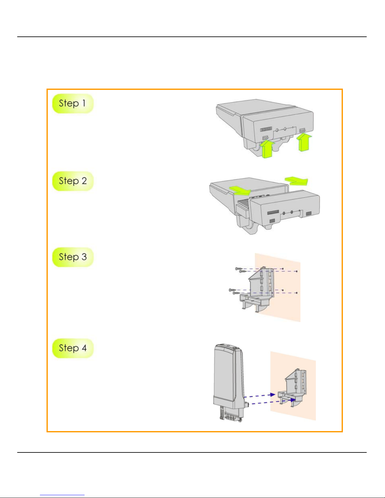
Hold the catches upward as shown
in the figure.
While still holding the catches, push
the Compex WPP54 cover
outwards.
Align the bracket to the wall, Use
the bracket as a guideline, m ake 4
marks and drill 4 holes into the wall.
Next, secure the brackets to the
wall as shown in the figure on the
right.
Align the main unit of Compex
WPP54 with the bracket to attach
them as shown in the figure.
Page 27
20
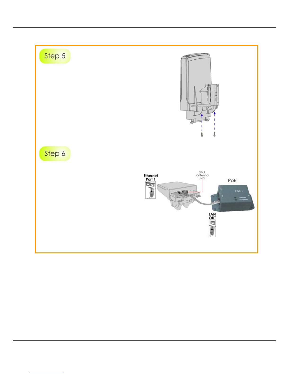
Next, fasten two screws that are
provided in the packaging to
secure the main unit to the
bracket.
Connect one end of an RJ45
Ethernet cable to the LAN OUT port
of the Injector and the other end to
Ethernet Port 1 of Compex WPP54.
Maximum length of the RJ45
Category 5 cable is 100 metres.
Next, connect your SMA antenna
(not provided) to the SMA reverse
connector.
Page 28
21
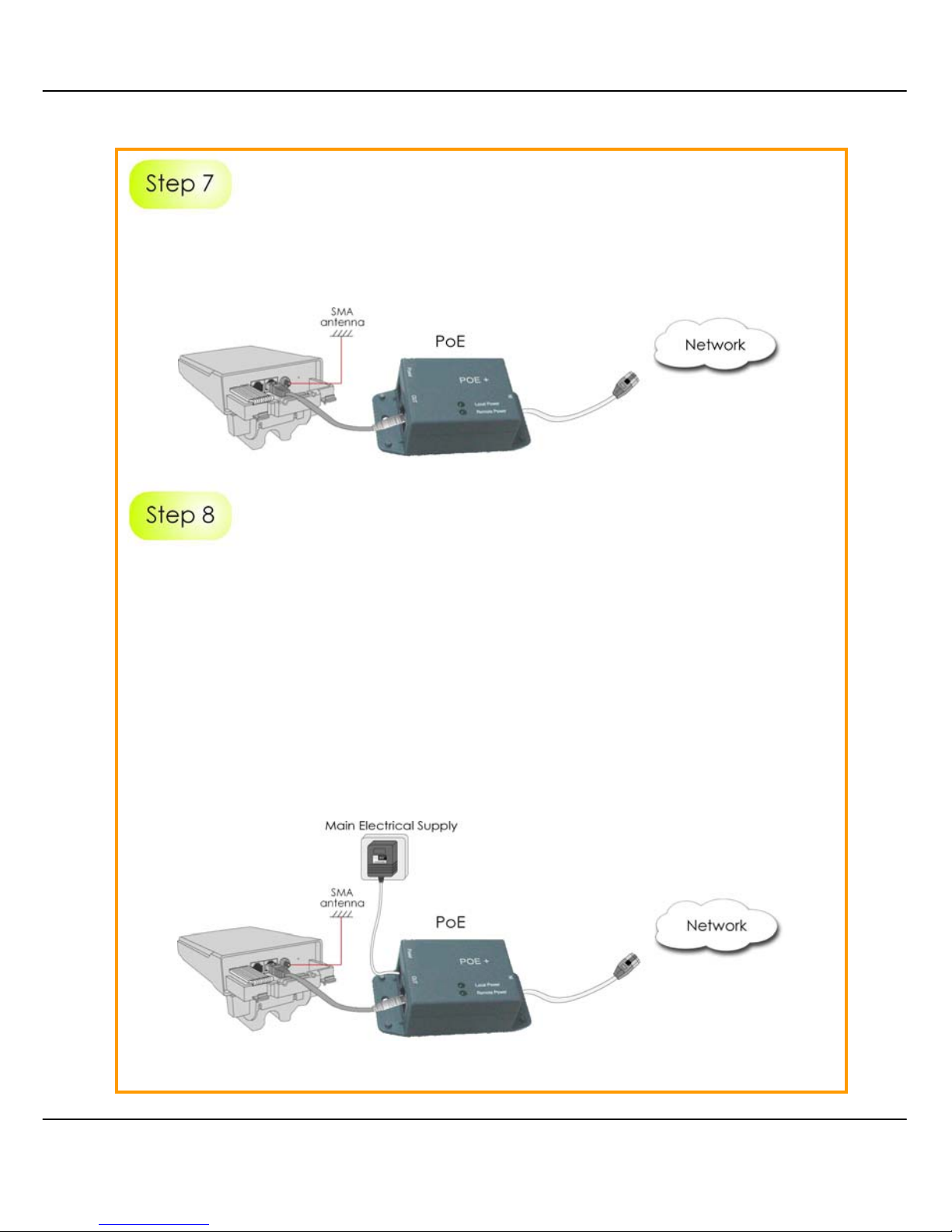
Connect the RJ45 Ethernet cable attached to th e Compex PoE Injector (not
provided) to a network device, such as to a s witch or to the PC you will use to
configure the WPP54.
Connect the power adapter in the Compex PoE kit (not prov ided) to the mai n
electrical supply and the power plug into the socket of the injector.
Now, turn on your power supply. Notice that the POWER LED has lighted up.
This indicates that the WPP54 is receiving power through the Compex PoE
Injector and that connection between Com pex WPP54 and your network has
been established.
Note:
Please use the power adapter in the Compex PoE kit (not provi ded). Using a
power adapter with a different voltage rating will damage this product.
Page 29
22
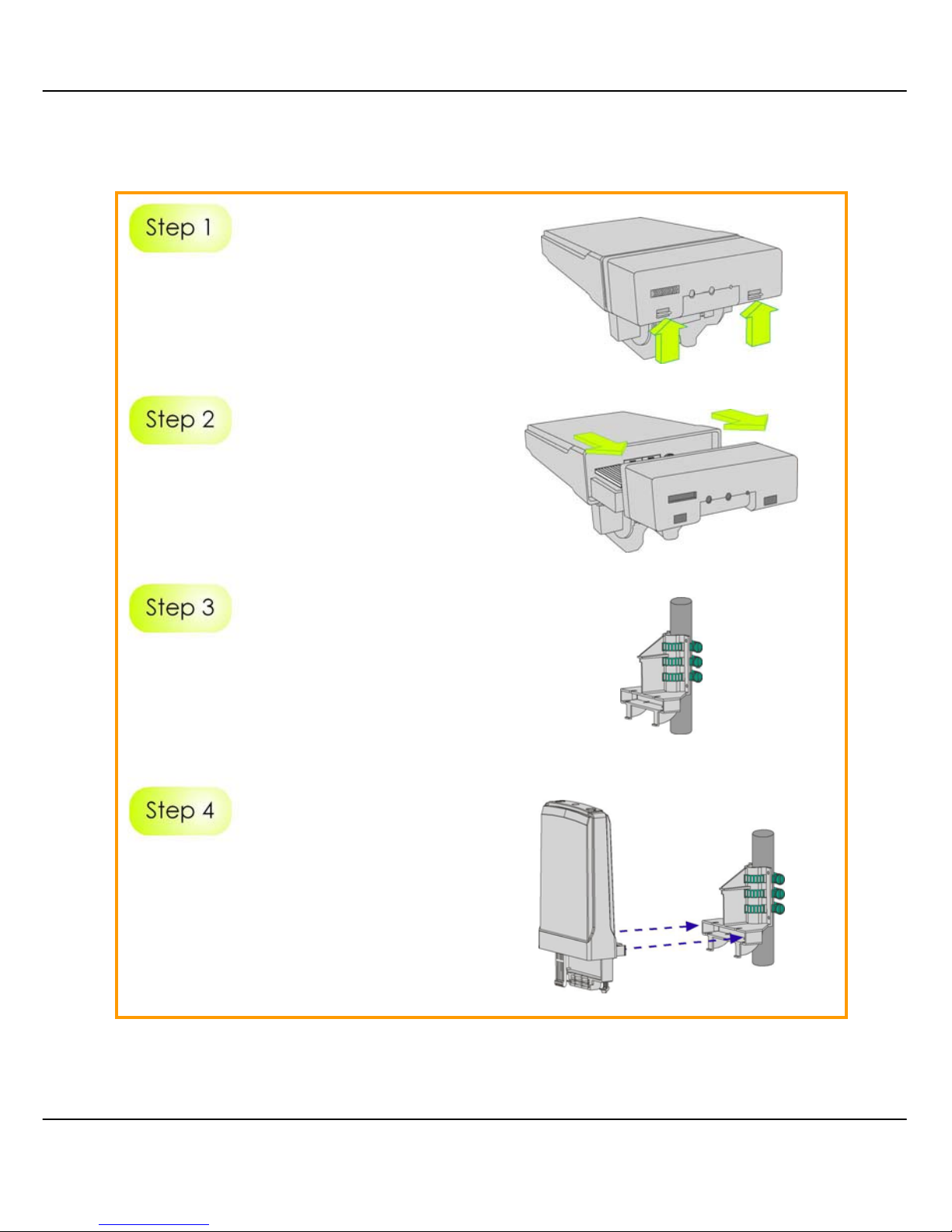
M
M
EETTHHOODD
T
T
WWO
O
:: M
M
OOUUNNTTIINNGG OONN TTHHEE
P
P
OOLLE
E
Hold the catches upward as shown
in the figure.
While still holding the catches, push
the Compex WPP54 cover outwards.
Use metal straps (not provided) to
secure the bracket to the pole.
Place the straps through the slots in
the bracket and then around the
pole. Tighten the straps.
Align the main unit of Compex
WPP54 with the bracket to attach
them as shown in the figure.
Page 30
23
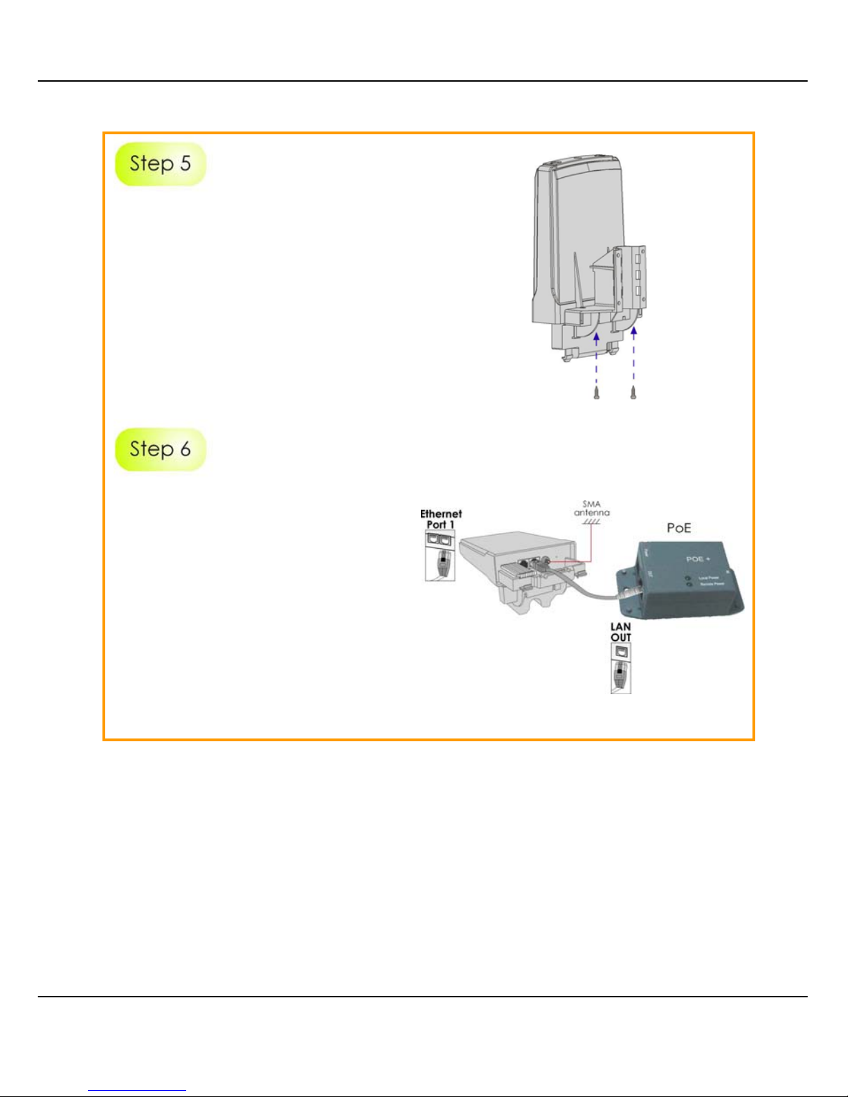
Next, fasten two screws that are
provided in the packaging to secure
both the main unit to the bracket.
Connect one end of an RJ45
Ethernet cable to the LAN OUT port
of the Injector and the other end to
Ethernet Port 1 of Compex WPP54.
Maximum length of the RJ45
Category 5 cable is 100 metres.
Next, connect your SMA antenna
(not provided) to the SMA reverse
connector.
Page 31
24
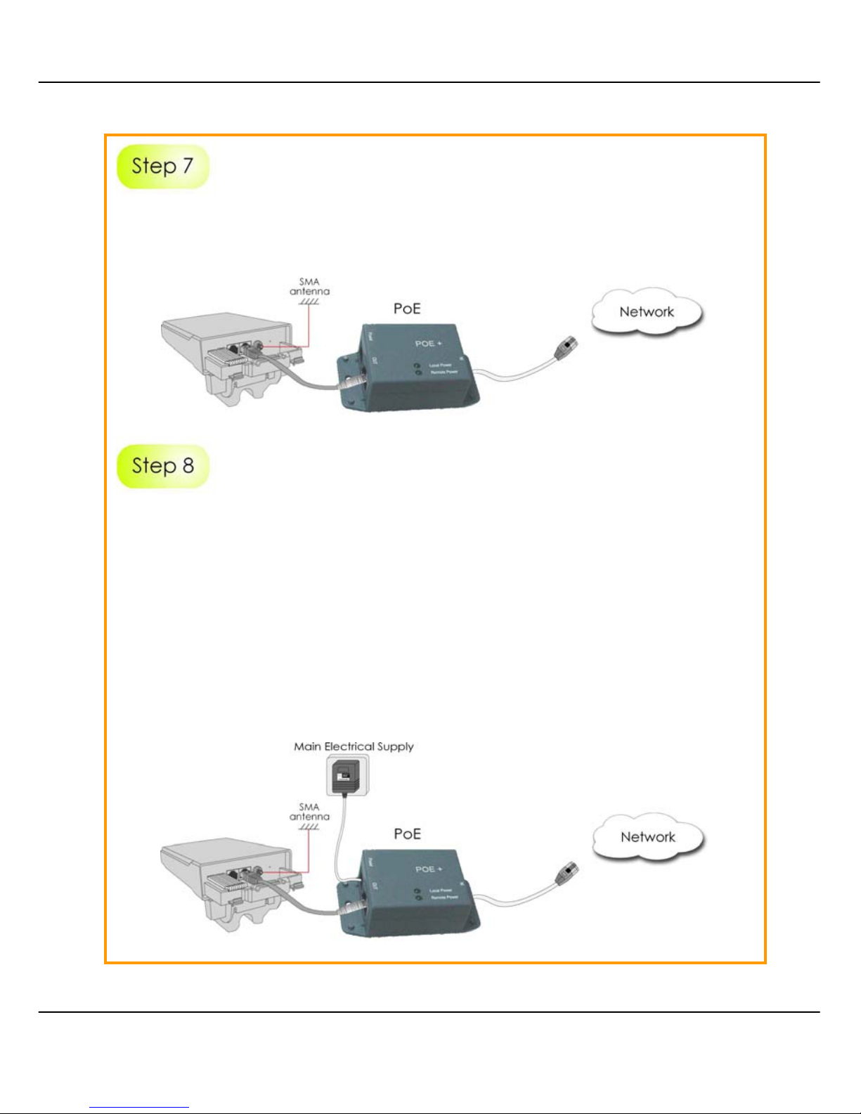
Connect the RJ45 Ethernet cable attached to th e Compex PoE Injector (not
provided) to a network device, such as to a s witch or to the PC you will use to
configure the WPP54.
Connect the power adapter in the Compex PoE kit (not prov ided) to the mai n
electrical supply and the power plug into the socket of the injector.
Now, turn on your power supply. Notice that the POWER LED has lighted up.
This indicates that the WPP54 is receiving power through the Compex PoE
Injector and that connection between Com pex WPP54 and your network has
been established.
Note:
Please use the power adapter in the Compex PoE kit (not provi ded). Using a
power adapter with a different voltage rating will damage this product.
Page 32

25
CChhaapptteerr 33:: AAcccceessss ttoo W
Weebb--bbaasseedd
IInntteerrffaaccee
There are two methods to access to the web-based Interface of your access
point:
••
TThhrroouugghh oouurr CCoommppeexx UUttiilliittyy –– uuCCoonnffiigg
You can access to the web-based interface directl y without the need to assi gn
a different IP address to your PC.
••
BByy eenntte
erriinngg tthhee IIPP aaddddrreessss ooff AAcccceessss ppooiinntt iinn tthhee aaddddrreessss bbaarr ooff IInntteerrnneett
EExxpplloorreerr
You need to assign an IP address to your PC, such as 192.168.168.x, where x
can take any value from 2 to 254, so that it is in the same subnet as Access
point.
A
A
CCCCEESSSS TTOO TTHHEE
W
W
EEBB IINNTTEERRFFAACCEE WWIITTHH U
U
C
C
OONNFFIIG
G
Compex has developed a powerful uConfig utility that has been desi gned to
give you direct access to the Web interface.
SStteepp 11::
Insert the Product CD into your CD-ROM drive. The CD will run automatically.
SStteepp 22::
From the UUttiilliittiieess section, select to install the uuCCoonnffiigg utility to your hard disk.
Page 33
26
SStteepp 33::
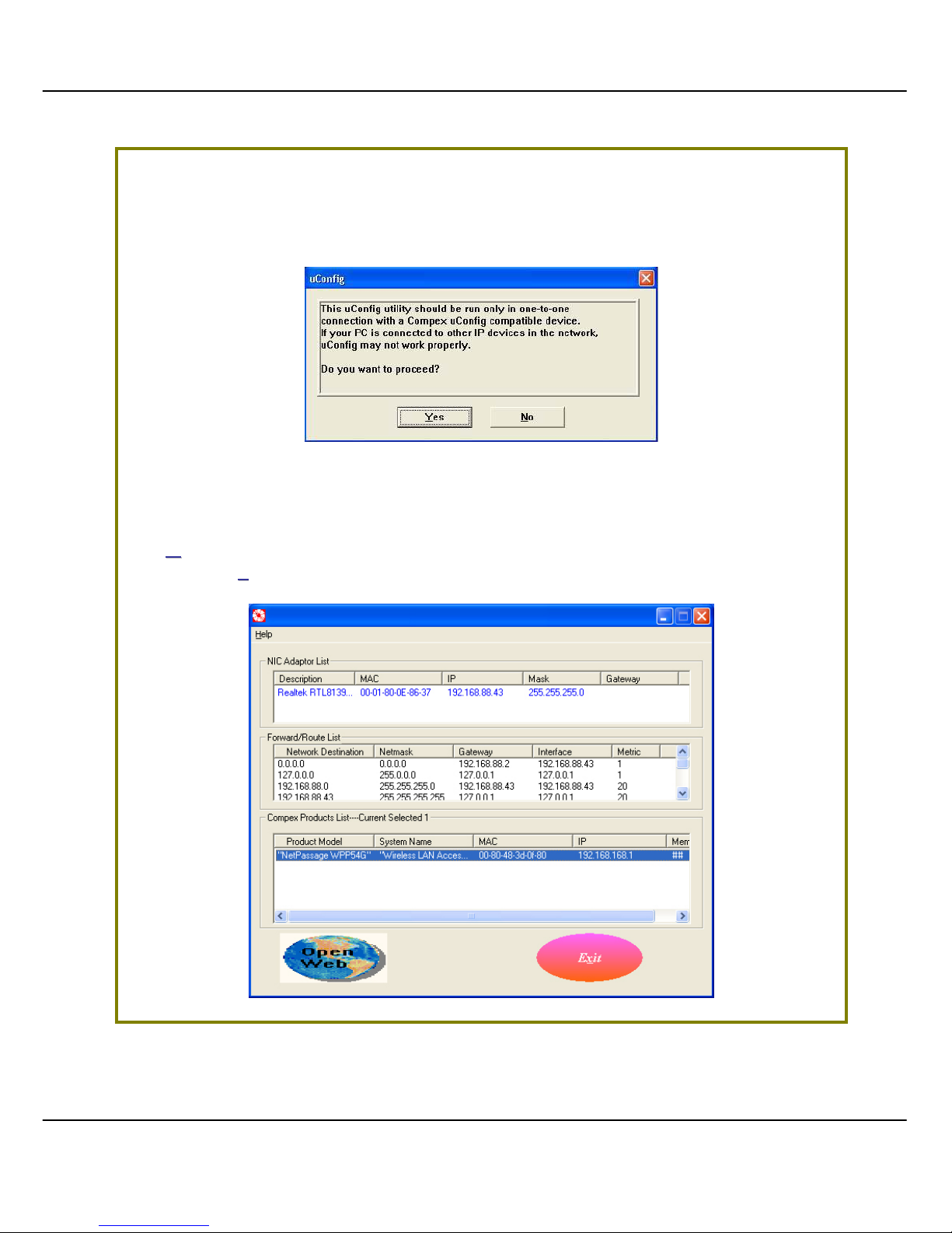
When the utility has been installed, double-click on the uuCCoonnffiigg icon. The
following screen will appear, click on the YYeess button to proceed.
SStteepp 44::
Select NNeettPPaassssaaggee WWPPPP5544GG in the CCoommppeexx PPrroodduuccttss LLiisstt section and click on
the OO
ppeenn WWeeb
b button. To retrieve and display the latest device(s) in the list,
click on the RR
eeffrreessh
h button.
Page 34
27
SStteepp 55::
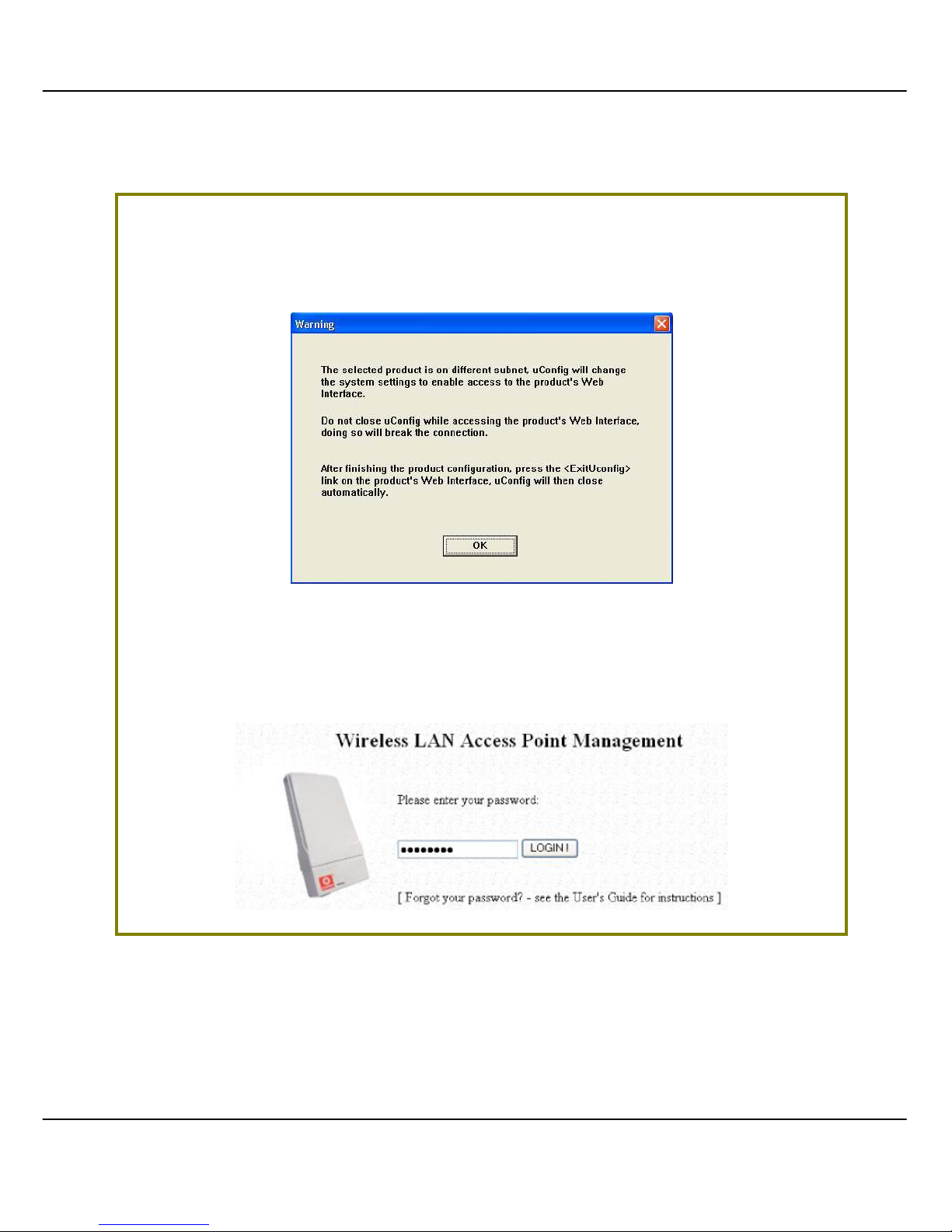
Do not exit the uConfig program whil e accessing to the web-based interface.
This will disconnect you from the device. Click on the OOKK button to proceed.
SStteepp 66::
At the login page, press the LLOOGGIINN!! button to enter the configuration page.
The default password is “password”.
Page 35
28
SStteepp 77::
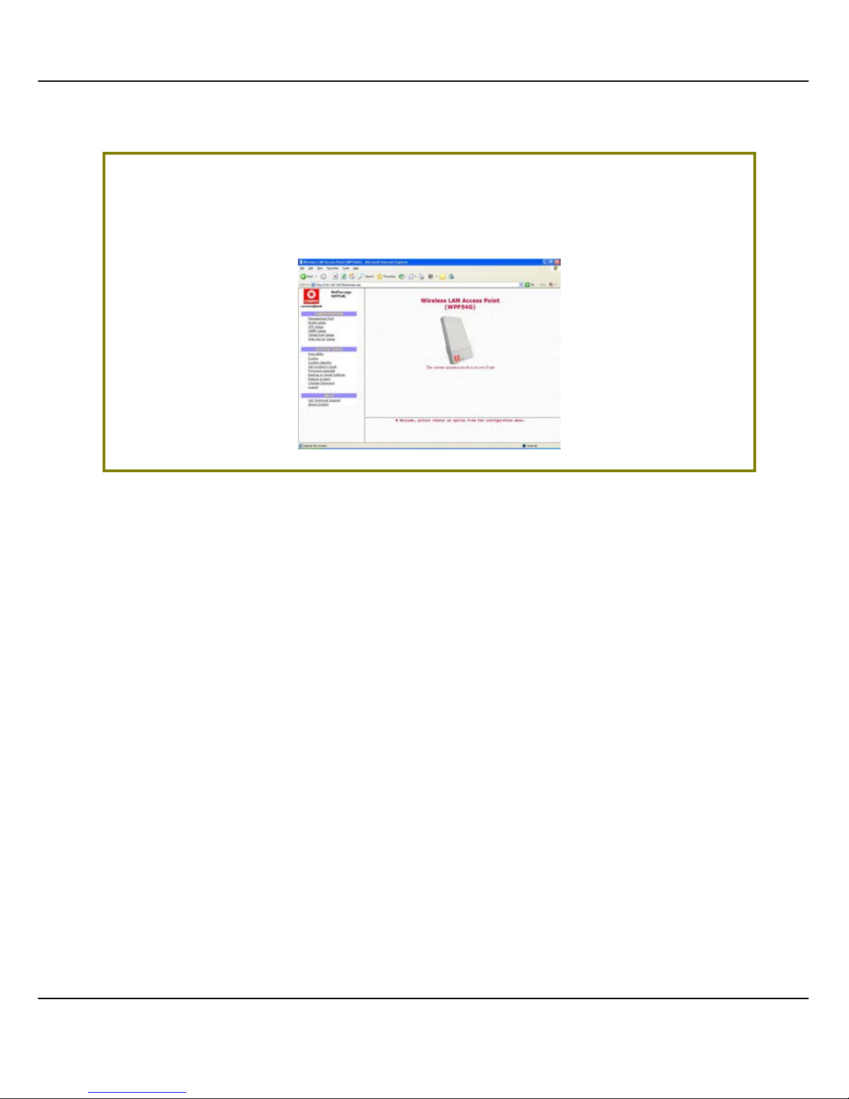
You will then reach the home page of your access point’s web-based
interface.
Page 36
29
M
M
AANNUUAALL AACCCCEESSSS TTOO WWEEB
B
-
-
BBAASSEEDD IINNTTEERRFFAACCEE VVIIAA
I
I
NNTTEERRNNEETT
E
E
XXPPLLOORREER
R
For this method, you need to assign an IP address to your PC so that it belongs
to the same subnet as your access point. In this example, we are using Windows
XP for illustration. For Windows 98/98SE/2000/NT/ME, kindly refer to Appendix II
“TCP/IP Configuration”.
SStteepp 11::
Go to your desktop, right-click on MMyy NNeettwwoorrkk PPllaacceess icon and select
PPrrooppeerrttiiees
s.
SStteepp 22::
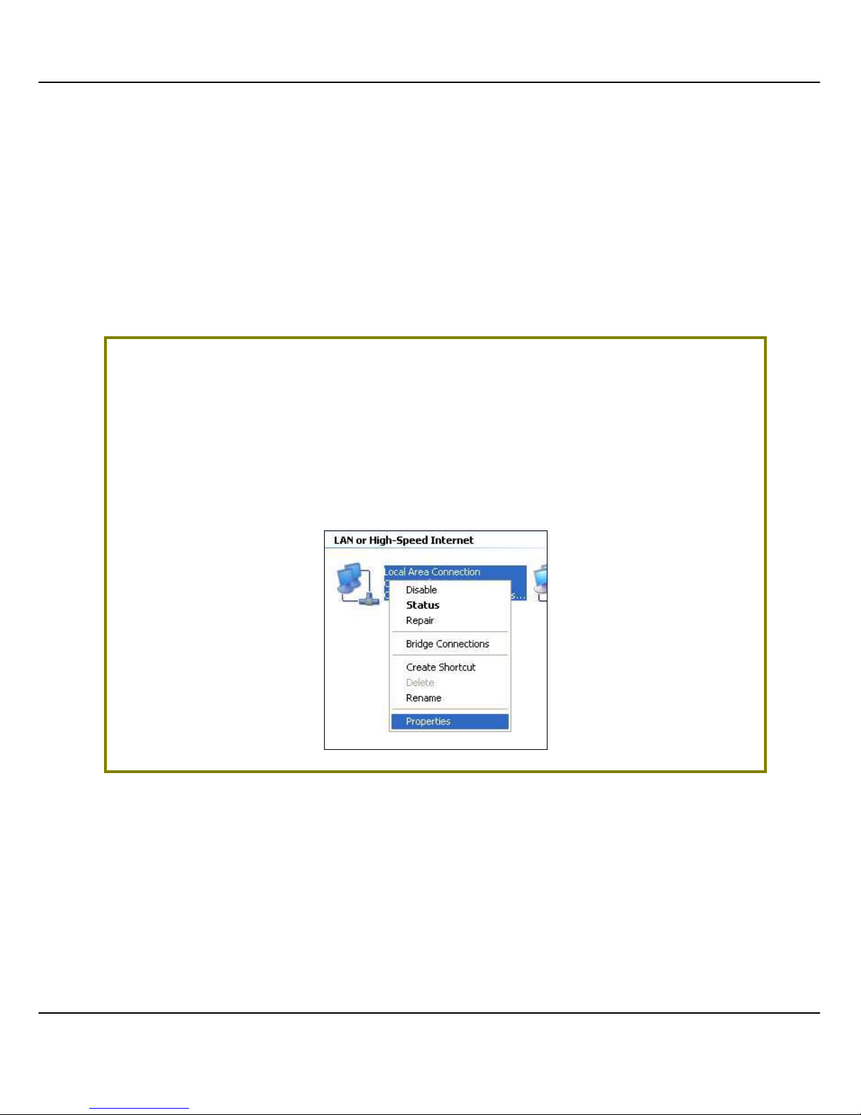
Go to your network adapter icon, right click and select PPrrooppeerrttiieess.
Page 37
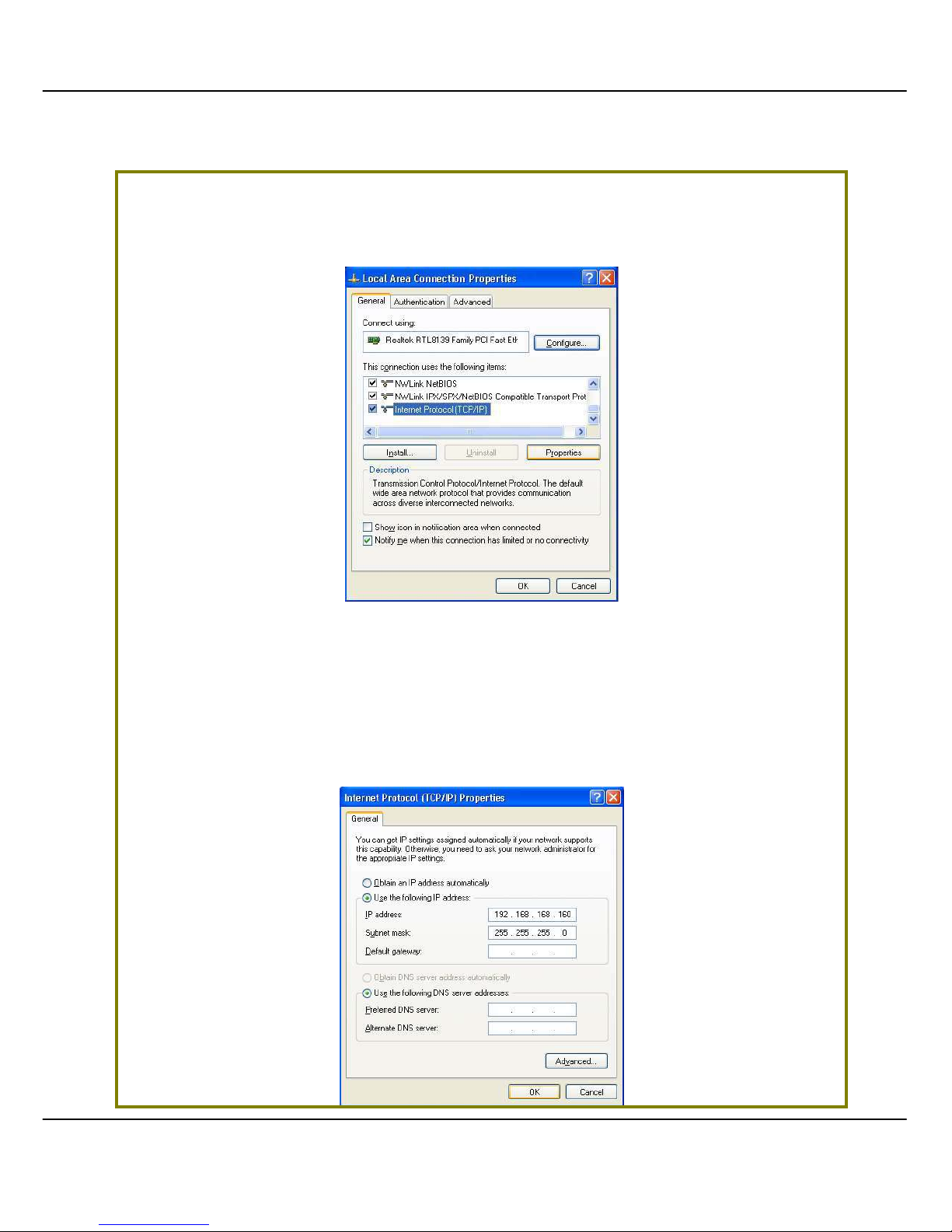
30
SStteepp 33::
Highlight IInntteerrnneett PPrroottooccooll ((TTCCPP//IIPP)) and click on the PPrrooppeerrttiieess button.
SStteepp 44::
Select the radio button for UUssee tthhee ffoolllloowwiinngg IIPP aaddddrreessss. Enter the IP Address
and Subnet Mask as 192.168.168.x and 255.255.255.0, where x can be any
number from 2 to 254, except 1. In this example, we are using 192.168.168.160
as the static IP Address.
Page 38
31
SStteepp 55::
Click on the OOKK button to close all windows.
SStteepp 66::
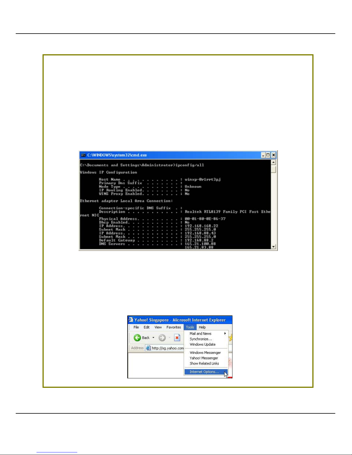
Next, in order to check if the IP address has been correctly assigned to your
PC, go to SSttaarrtt menu, AAcccceessssoorriieess, select CCoommmmaanndd PPrroommpptt and type the
command ipconfig/all.
Your PC is now ready to configure your access point.
SStteepp 77::
Launch your Web browser. Under the TToooollss tab, select IInntteerrnneett OOppttiioonnss.
Page 39
32
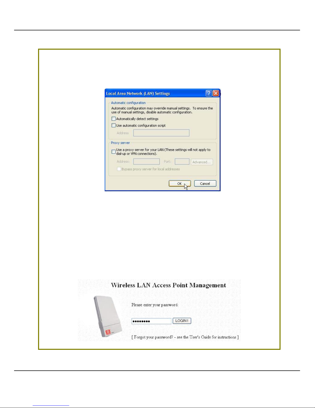
SStteepp 88::
Open the CCoonnnneeccttiioonnss tab and in the LLAANN SSeettttiinnggss section, disable all the
option boxes. Click on the OOKK button to update the changes.
SStteepp 99::
At the AAddddrreessss bar, enter http://192.168.168.1 and press EEnntteerr on your
keyboard.
SStteepp 1100::
At the login page, click on the LLOOGGIINN!! button to enter the configuration
pages.
Page 40
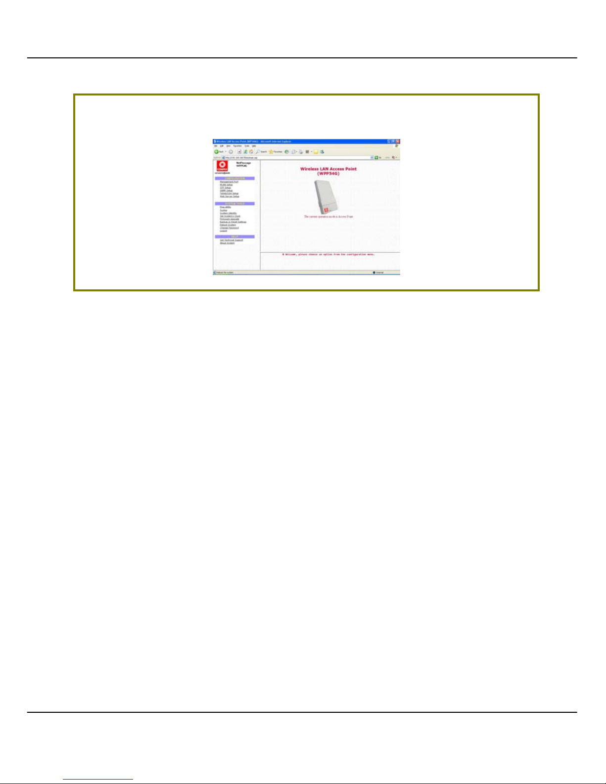
33
You will then reach the home page of your access point’s Web interface.
Page 41

34
CChhaapptteerr 44:: CCoom
m
m
moonn CCoonnffiigguurraattiioonn
This chapter illustrates the following features, which are available in ALL
the
operating modes of your access point, unless stated otherwise.
••
MMaannaaggeemmeenntt PPoorrtt
••
WWLLAANN BBaassiicc SSeettuupp
••
WWLLAANN SSeeccuur
r
iittyy
••
SSTTPP SSeettuupp
••
SSNNMMPP
••
MMAACC FFiilltteerriinngg
••
AAnntteennnnaa AAl
liiggnnmmeenntt
M
M
AANNAAGGEEMMEENNTT
P
P
OORRTT
S
S
EETTUUP
P
This section shows you how to customize the parameter s of your access poi nt to
suit the needs of your network. It also explai ns how to make use of the built-in
DHCP server of your access point.
Page 42
35
S
S
EETTTTIINNGG UUPP YYOOUURR
LLAANN
You can opt to adjust the default values of your access point and customize
them to your network settings.
SStteepp 11::
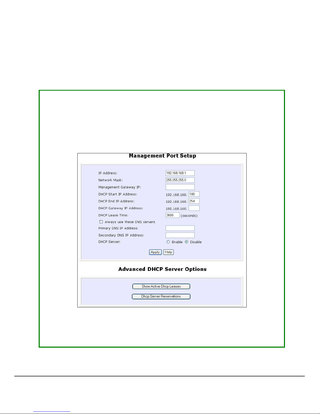
Click on MMaannaaggeemmeenntt PPoorrtt from the CCOONNFFIIGGUURRAATTIIOONN menu.
In the MMaannaaggeemmeenntt PPoorrtt SSeettuupp page, refer to the table bel ow to replace the
default settings of Access point with appropriate values to suit the needs of
your network.
SStteepp 22::
Click on the AAppppllyy button to save your new parameters.
Page 43

36
This table descri bes the parameters that can be modifi ed in the Management
Port Setup page.
Parameters Description
IP Address When the DHCP server of the access point is enabled (unless you
set a different DHCP Gateway IP Address), this LAN IP Address
would be allocated as the Default Gateway of the DHCP client.
The IP address of your Access point is set by default to
192.168.168.1.
Network Mask The Network Mask serves to identify the subnet in which your
Access point resides. The default network mask is 255.255.255.0.
Management
Gateway IP
(Optional) As a bridge Access Point, the access point does not
usually communicate with devices on other IP subnets. However,
the Management Gateway here acts as the equivalent of the
Default Gateway of a PC, to allow the access point to
communicate with devices on different subnets. For instance, if
you want to access the access point from the Internet or from a
router on the LAN, enter the router IP address in the
Management Gateway IP field.
The Management Gateway IP address of your access point is set
to nil by default.
The next two fields (DHCP Start IP Address and DHCP End IP Address) allow you to define
the range of IP addresses from which the DHCP Server can assign an IP address to the
LAN.
DHCP Start IP
Address
This is the first IP address that the DHCP server will assign. The
value that you input here should belong to the same subnet as
your access point. For example, if the IP address and network
mask of your access point are 192.168.168.1 and 255.255.255.0
respectively, the DHCP Start IP Address should be 192.168.168.X,
where X can take any value from 2 to 254. It is pre-set to
192.168.168.100.
DHCP End IP
Address
This is the last IP address that the DHCP server can assign. It
should also belong to the same subnet as your access point. For
instance, if the IP address and network mask of your access point
are 192.168.168.1 and 255.255.255.0 respectively, the DHCP End
IP Address should be 192.168.168.X, where X can take any value
from 2 to 254. It is pre-set as 192.168.168.254.
Page 44

37
Parameters Description
DHCP Gateway IP
Address
Though usually, the DHCP server also acts as the Default
Gateway of the DHCP client, the access point gives you the
option to define a different Gateway IP Address, which will be
allocated as the Default Gateway IP of the DHCP client. The
DHCP client will thus receive its dynamic IP address from the
access point but will access to the Internet or to the other LAN
through the Default Ga teway defin ed by the DHCP Gateway IP
Address.
For instance, if the access point is used in Access Point Client
mode and connects to an Internet gateway, X, a PC wired to
the access point will be unable to obtain a dynamic IP address
directly from X. But if you can enable the DHCP server of the
access point and set the IP address of X as the DHCP Gateway IP
Address, the PC will then obtain its IP address from the access
point and access the Internet through X.
Always use these
DNS servers
Enable this checkbox if you want the access point to only use
the DNS server(s) you have specified below.
Primary DNS IP
Address
Your ISP usually p rovides the IP address of the DNS server.
Secondary DNS IP
Address
This optional field is reserved for the IP address of a secondary
DNS server.
DHCP Server If you disable the DHCP server, you will need to manually
configure the TCP/IP parameters of each computer in your
network.
Page 45
38
T
T
OO VVIIEEWW TTHHEE AACCTTIIVVEE
DDHHCCPP
LLEEAASSEES
S
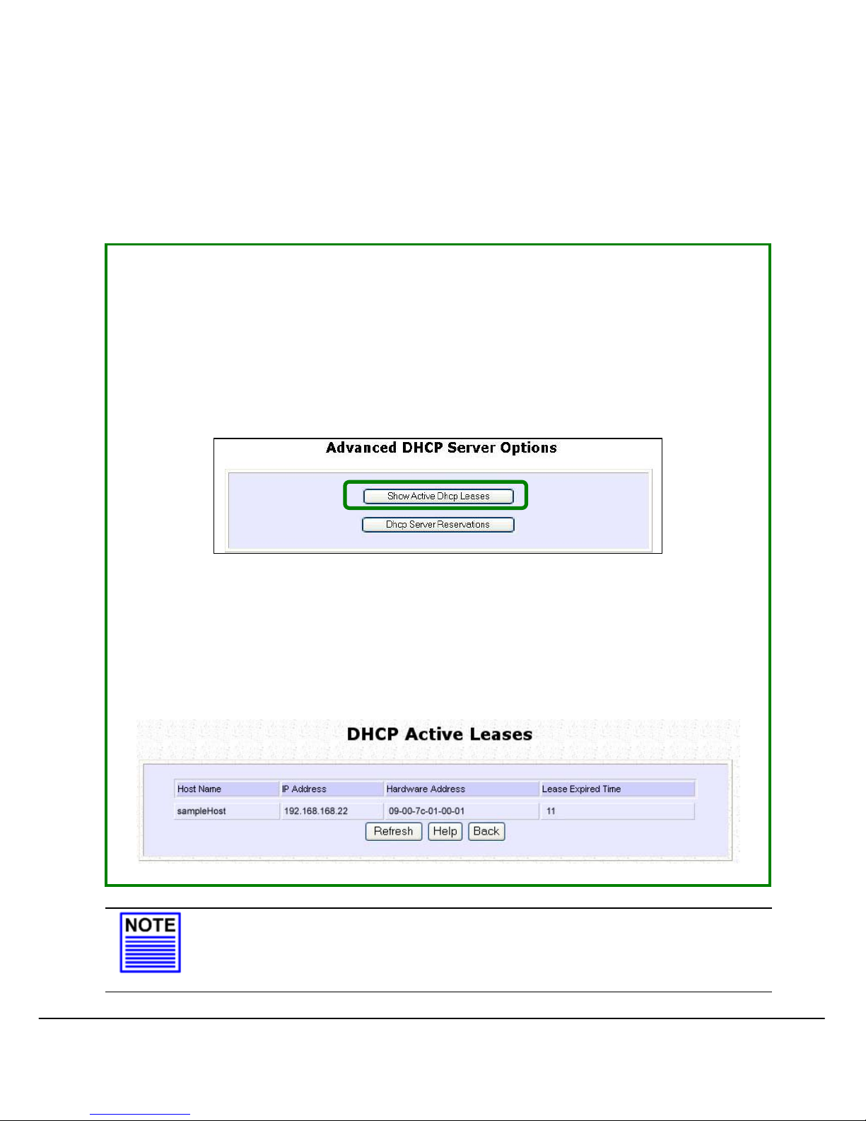
The following will guide you to a page display of the active IP address leases
that have been allocated by the buil t-in DHCP server of Access point.
SStteepp 11::
Click on MMaannaaggeemmeenntt PPoorrtt from the CCOONNFFIIGGUURRAATTIIOONN menu.
SStteepp 22::
Go to the AAddvvaanncceedd DDHHCCPP SSeerrvveerr OOppttiioonnss section, click on the SShhooww AAccttiivvee
DDHHCCPP lleeaasse
e
s
s button.
The DHCP Active Leases table displays:
• The Host Name of the DHCP client
• The IP Address that has been allocated to the DHCP client
• Its Hardware (MAC) Address
• The Lease Expired Time.
NOTE
Invalid date and time displayed in the Lease Expired Time column
indicates that the clock of your acc ess poi nt has not b een proper ly
set. Please refer to the SYSTEM TOOLS
section for more details on
Page 46
39
how to set the system clock.
T
T
OO RREESSEERRVVEE SSPPEECCIIFFIICC
IIPP
AADDDDRREESSSSEESS FFOORR PPRREEDDEETTEERRMMIINNEEDD
DDHHCCPP
CCLLIIEENNTTS
S
Making an IP address reservation lets you inform the DHCP server to exclude
that specific address from the pool of free IP addresses it draws on for dynami c
IP address allocation.
For instance, if you set up a publicly accessible FTP/HTTP server within your
private LAN, while that server would require a fixed IP address, you would still
want the DHCP server to dynamically allocate IP addresses to the rest of the
PCs on the LAN.
The following shows you how to reserve a particular IP address.
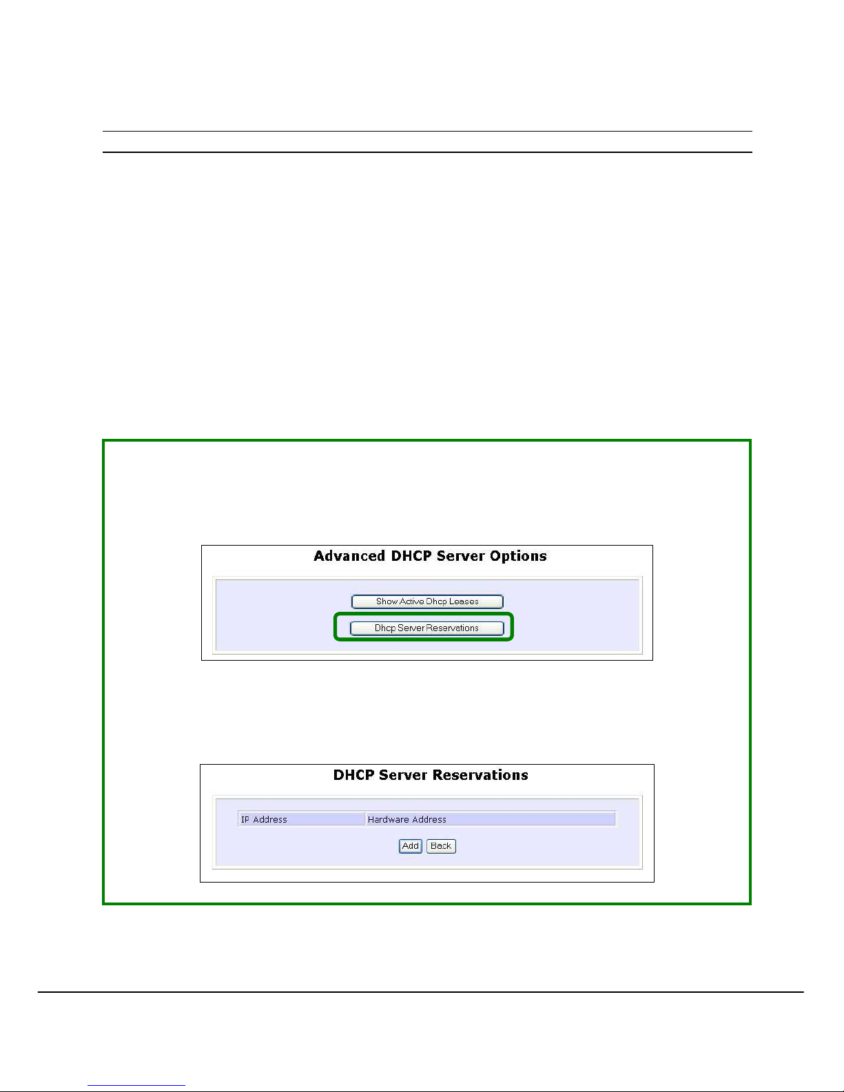
SStteepp 11::
From the AAddvvaanncceedd DDHHCCPP SSeerrvveerr Options section, click on the DDHHCCPP SSeerrvveerr
RReesseerrvvaattiioonnss
button.
SStteepp 22::
Click on AAdddd button.
Page 47
40
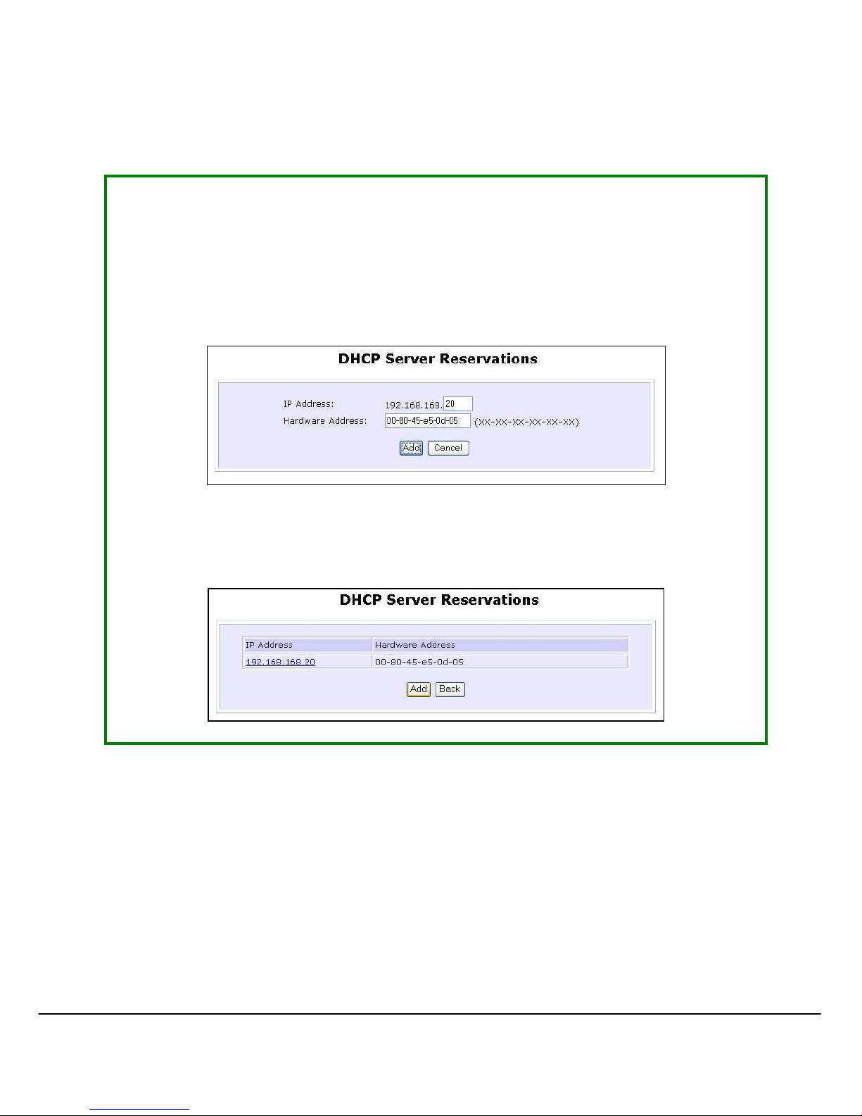
SStteepp 33::
Fill in:
The host portion of the IP Address to reserve.
The Hardware Address, in pairs of two hex values
Press the AAppppllyy button to make your new entry effective.
The DDHHCCPP SSeerrvveerr RReesseerrvvaattiioonnss page will then be refreshed to illustrate the
currently reserved IP addresses.
Page 48
41
D
D
EELLEETTEE
DDHHCCPP S
S
EERRVVEERR RREESSEERRVVAATTIIOON
N
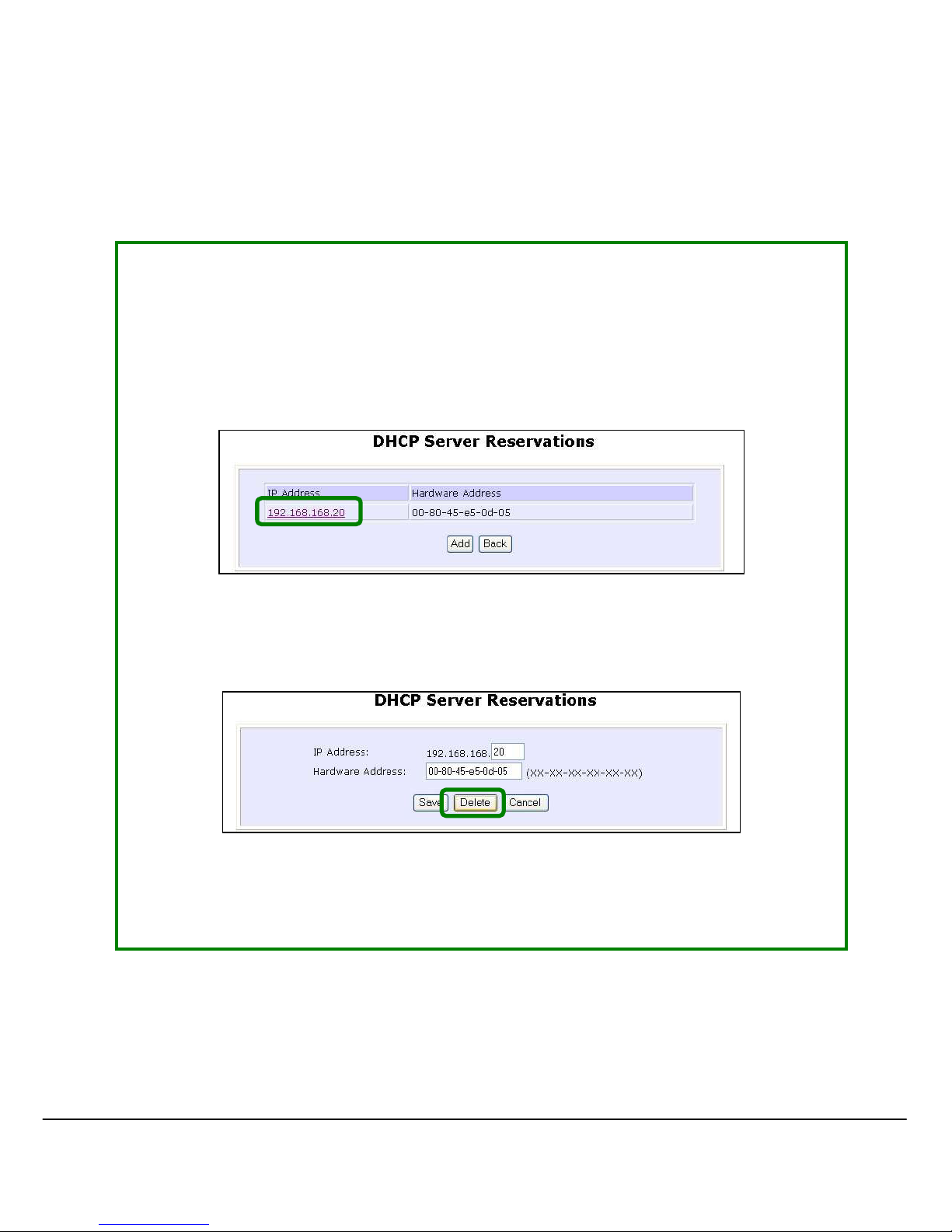
If you do not need the DHCP server to reserve an IP address anymore, you
can delete the DHCP Server Reservation.
SStteepp 11::
Click on the reserved IP address that you wish to delete, e.g. 192.168.168.20.
SStteepp 22::
Click on the DDeelleettee button.
The DDHHCCPP SSeerrvveerr RReesseerrvvaattiioonnss table will then be refreshed to reflect your
changes.
Page 49

42
WWLLAANN S
S
EETTUUP
P
This section shows how to perform the following functions:
Basic
:
This function performs a basic setup of the operation modes.
Security
:
This function performs data encryption and protection for the access point.
Kindly refer to Chapter 5 on WLAN Security for details.
Advanced
:
This function furthers the basi c configuration of the access point by setting th e
system’s additional Long Distance Parameters.
Kindly refer to Chapter 6 on Wireless Extended Features for details.
Statistics
:
This function uses the Scan Feature to monitor and interpret the statistics data
collected.
MAC Filtering
(only applicable to Access Point mode):
MAC Filtering acts as a security measure by restricting the users accessing to
the network through their MAC address.
Antenna Alignment
:
It is a tool for aligning outdoor antenna between 2 access points over long
distances. The signal level can be checked from the web page and also from
the DIAG LED indicator.
Page 50
43
T
T
OO CCOONNFFIIGGUURREE TTHHEE
B
B
AASSIICC SSEETTUUPP OOFF TTHHEE WWIIRREELLEESSSS MMOODDE
E
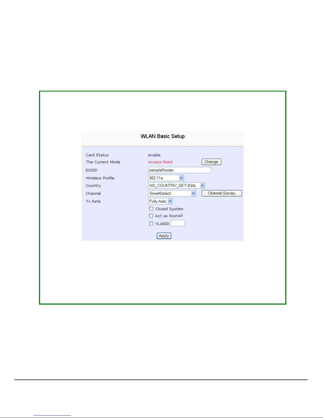
The following will guide you to configure the basi c setup of the wireless mode
you have selected.
SStteepp 11::
Click on WWLLAANN SSeettuupp from the CCOONNFFIIGGUURRAATTIIOONN menu. You will see the sub-
menus expanded under WWLLAANN SSeettuupp. Click on BBaassiicc.
The default operating mode of Access point is the Access Point mode.
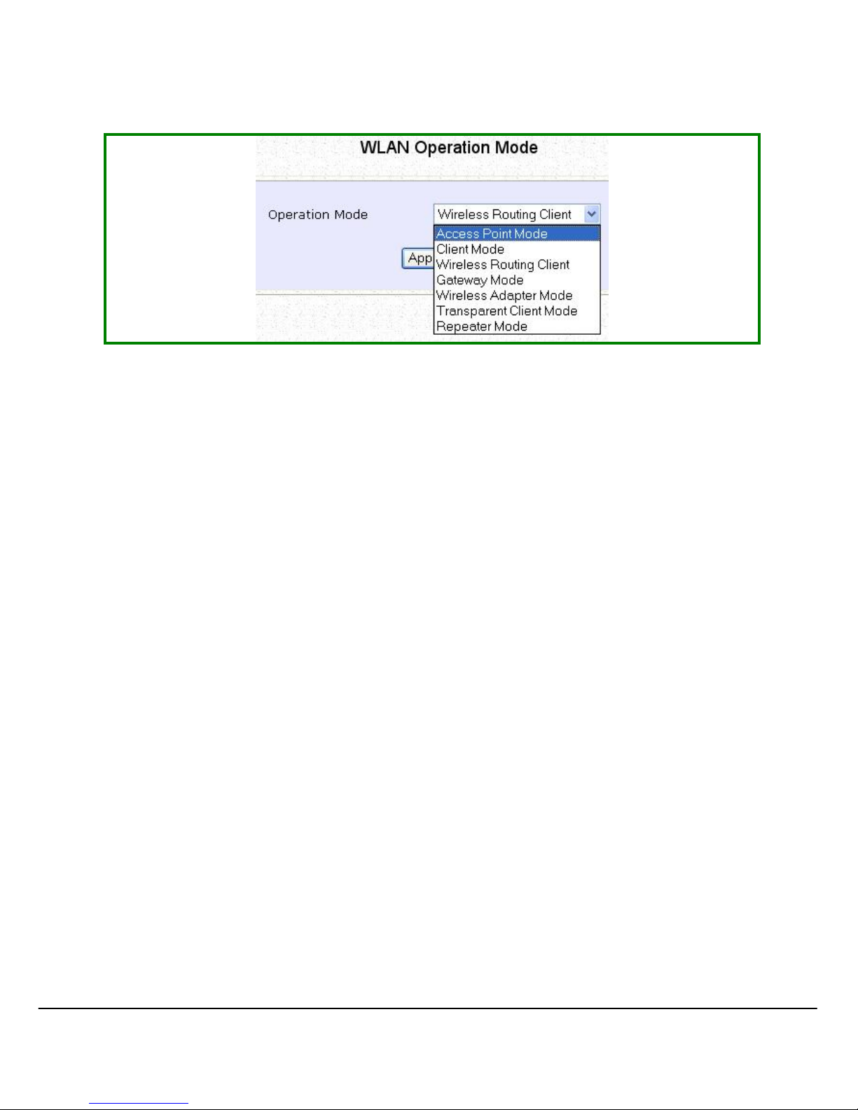
SStteepp 22:: ((OOppttiioonnaall:: CChhaannggee CCuurrrreenntt mmooddee))
If you wish to change the current mode of your access point, click on
CChhaanngge
e, select your OOppeerraattiioonn MMooddee and click on the AAppppllyy button to
access the setup page of your selected mode. Then you are prompted to
reboot the access point so as to activate the mode setting.
Page 51
44
Page 52
45
SStteepp 33::
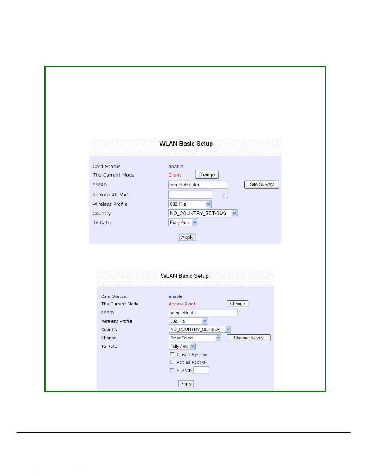
Enter the parameters in thei r respective fields, click on the AAppppllyy button and
reboot your device to let your changes take effec t.
Note that the WWLLAANN BBaassiicc SSeettuupp pages for the modes are different.
Example: WWLLAANN BBaassiicc SSeettuupp page for CClliieenntt MMoodd
e
e
Example: WWLLAANN BBaassiicc SSeettuupp page for AAcccceessss PPooiinntt
This table describes the parameters that can be modified in the WWLLAANN BBaassiicc
SSeettuup
p page.
Page 53

46
Parameters Description
The Current Mode The default operating mode of the access point is the
Access Point mode. The access point can operate in 6
modes:
• Access Point Mode
• Client Mode
• Wireless Routing Client
• Gateway Mode
• Wireless Adapter Mode
• Transparent Client Mode
• Repeater Mode
You can toggle the mode by clicking on the CChhaannggee
button.
ESSID Enter a preferred name for the wireless network. Your
wireless clients must be configured with the same ESSID.
This case-sensitive entry can consi st of a maximum of 32
characters.
Site Survey
A list of wireless devices that are detected by your
access point in the WLAN. Information such as MAC
address, channel, SSID, algorithm and signal strength can
be found in the listing.
Page 54

47
Wireless Profile A selection of network environment types in which to
operate the access point:
••
880022..1111bb oonnllyy
This mode supports wireless B clients with data rates of up
to 11Mbps in the frequency range of 2.4GHz.
••
880022..1111bb//gg mmiixxeedd
This mode supports both wireless B and G clients.
••
880022..1111gg oonnl
lyy
This mode supports wireless-G clients that offer
transmission rates of up to 54Mbps in the 2.4GHz
frequency band.
Country Choose the Country where you are located.
Channel
This option allows you to select a frequ ency channel for
the wireless communication. This parameter is only
available in the Access Point, Transparent Client, and
Repeater modes.
Select SmartSelect to automatically scan and
recommend the best channel that the access point can
utilize.
Tx Rate Allow you to choose the rate of data transmission from
1Mbps to Fully Auto.
Closed System The access point will not broadcast its WLAN name
(ESSID) when Closed system is enabled. By default
Closed system is disabled.
Page 55

48
Act as RootAP
The access point will connect with one or multiple clients to
create a point-to-point and point-to-multi-point connections
network with 2 or more APs.
This connection method is fully compliant with 802.1h standards.
VLANID
Select and specify the VLANID.
This is a number to identify the different virtual network segments
to which the network devices are grouped.
This can be any number from 1 to 4094.
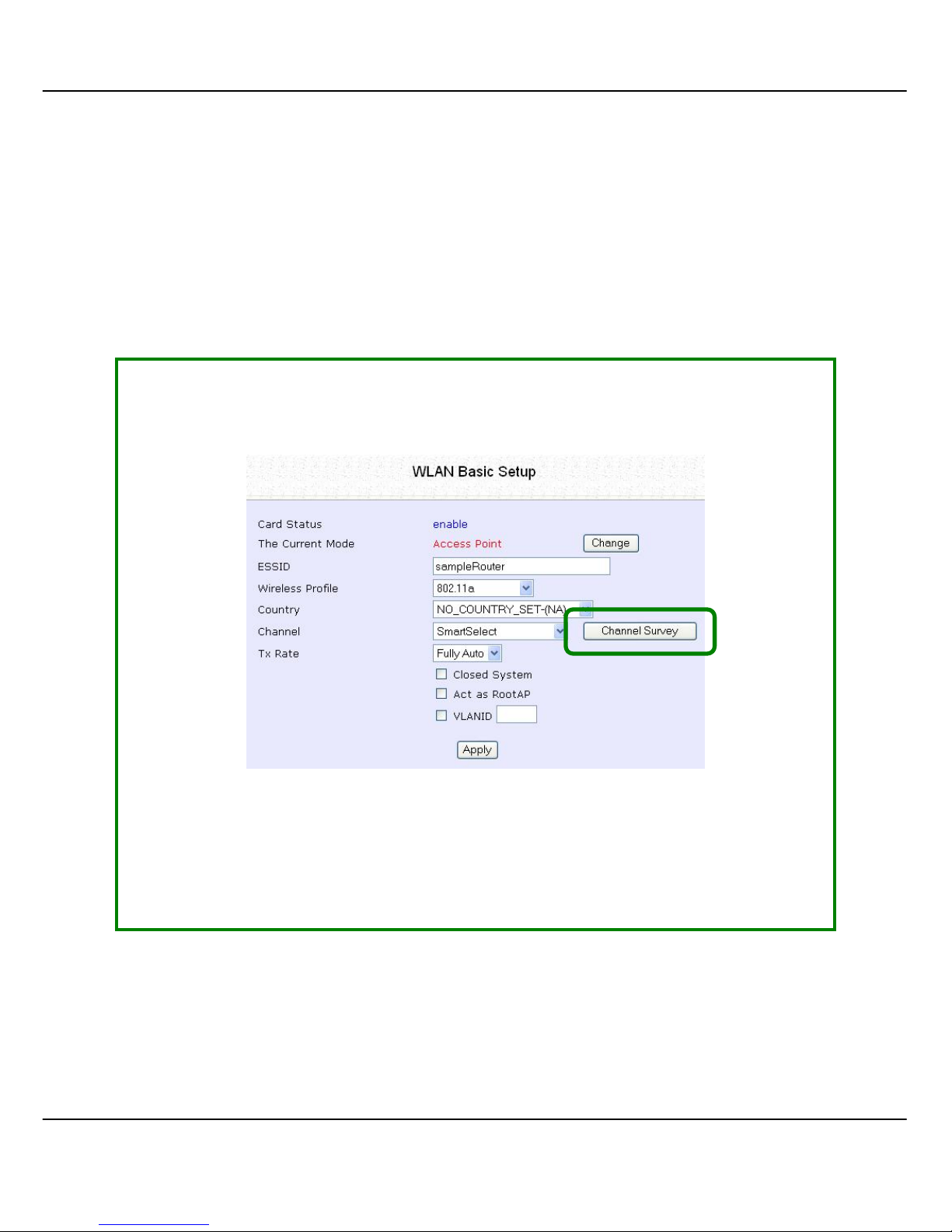
Channel Survey
A list of channels that are detected by your access point
in the WLAN. Information such as frequency, channel,
MyQuality, NeighQuality, APCount and
Recommendation can be found in the listing.
The Access Point and Gateway modes support this
feature.
Page 56
49
S
S
CCAANN FFOORR
S
S
IITTEE
S
S
UURRVVEEYY
((O
O
NNLLYY
F
F
OORR
C
C
LLIIEENNTT
M
M
OODDEE AANNDD
W
W
IIRREELLEESSSS
R
R
OOUUTTIINNGG
C
C
LLIIEENNTT
M
M
OODDEE
))
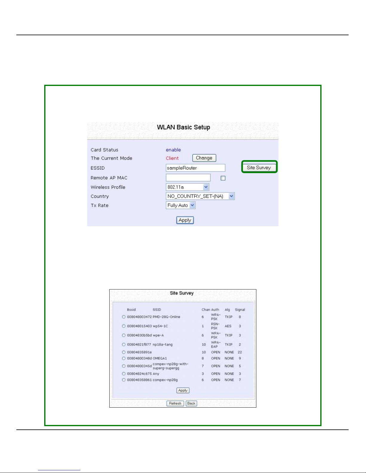
SStteepp 11::
In the MMooddee SSeettuupp page, click on the SSiittee SSuurrvveeyy button.
The SSiittee SSuurrvveeyy provides a list of the MMAACC aaddddrreesssseess ((BBSSSSIIDD)) and SSSSIIDD of
neighbouring access points detected, the CChhaann (channels), AAuutthh
(Authentication), AA
l
lgg (Algorithm) used, and the strength of the SSiiggnnaall
received.
Page 57

50
SStteepp 22::
To connect the WPP54GG-client to one of the access points detected:
Select the radio button corresponding to the access point you want to
connect to.
SStteepp 33::
Click on the AAppppllyy button to effect the change and return to the setup
page.
SStteepp 44::
Click on the RReeffrreesshh button to update this screen.
This table describes the read-only parameters of neighbouring access points
that can be viewed from the Site Survey page.
Parameters Description
Bssid In an infrastructure wireless network, the BSSID refers to
the wireless MAC address of the access point.
SSID Refers to the network name that uniquely identifies the
network to which the access point is connected.
Chan Refers to the channel being used for transmissi on.
Auth Refers to the types of authentic ation, such as WPA , WPA-
Personal, etc being used by the access point.
Alg Refers to the types of algorithm, such as WEP, TKIP, etc
being used by the access point.
Signal Describes the strength of the signal received in
percentage.
Page 58

51
NOTE
The purpose of using Site Survey is to scan and display all access
points based on the current security setting of your access point.
For instance, the following informati on supplied by the Site Surv ey
according to the security setting is explained:
• If the security mode i s set to None or WEP, the scan will show
all available access points that have no security or WEP
security
• If the security mode is set to WPA-Personal, the scan will show
all available access points having all types of securi ty from no
security, WEP security to WPA-Personal security.
Page 59
52
S
S
HHOOWW
L
L
IINNKK
I
I
NNFFOORRMMAATTIIOONN
((O
O
NNLLYY
F
F
OORR
C
C
LLIIEENNTT
M
M
OODDEE AANNDD
W
W
IIRREELLEESSSS
R
R
OOUUTTIINNGG
C
C
LLIIEENNTT MMOODDE
E
))
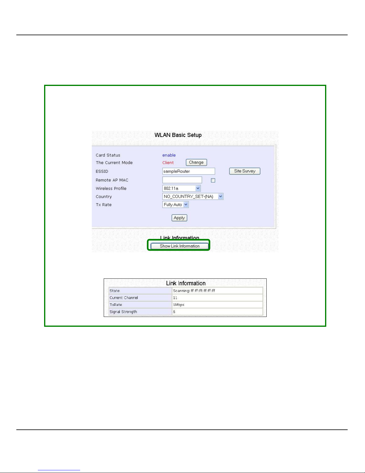
SStteepp 11::
To view the connecti on status when WPP5 4GG-client is linked to ano ther access
point, click on the SShhooww LLiinnkk IInnffoorrmmaattiioonn button.
The LLiinnkk IInnffoorrmmaattiioonn table illustrates the following data:
Page 60

53
This table describes the parameters that can be viewed from the LLiinnkk
IInnffoorrmmaattiioon
n page.
Parameters Description
State Refers to the MAC address of the BSS (AP to which the
WPP54GG-client is connected).
Current Channel The channel that is being presently used for transmission.
Tx Rate The rate of data transmission in Mbps.
Signal Strength Given in percentage, showing the intensity of the signal
received.
Page 61
54
S
S
CCAANN FFOORR
C
C
HHAANNNNEELL
S
S
UURRVVEEYY
(
(
AAVVAAIILLAABBLLEE
F
F
OORR
A
A
CCCCEESSSS
P
P
OOIINNTT
M
M
OODDEE AANNDD
G
G
AATTEEWWAAYY
M
M
OODDEE
))
Channel Survey provides a li st of all channels that are supported by th e access
point. This feature will show relative interference of all channels and
recommend the least congested channel.
When the users want to scan for and find the best channel, they can use
Channel Survey.
SStteepp 11::
In the MMooddee SSeettuupp page, click on the CChhaannnneell SSuurrvveeyy button.
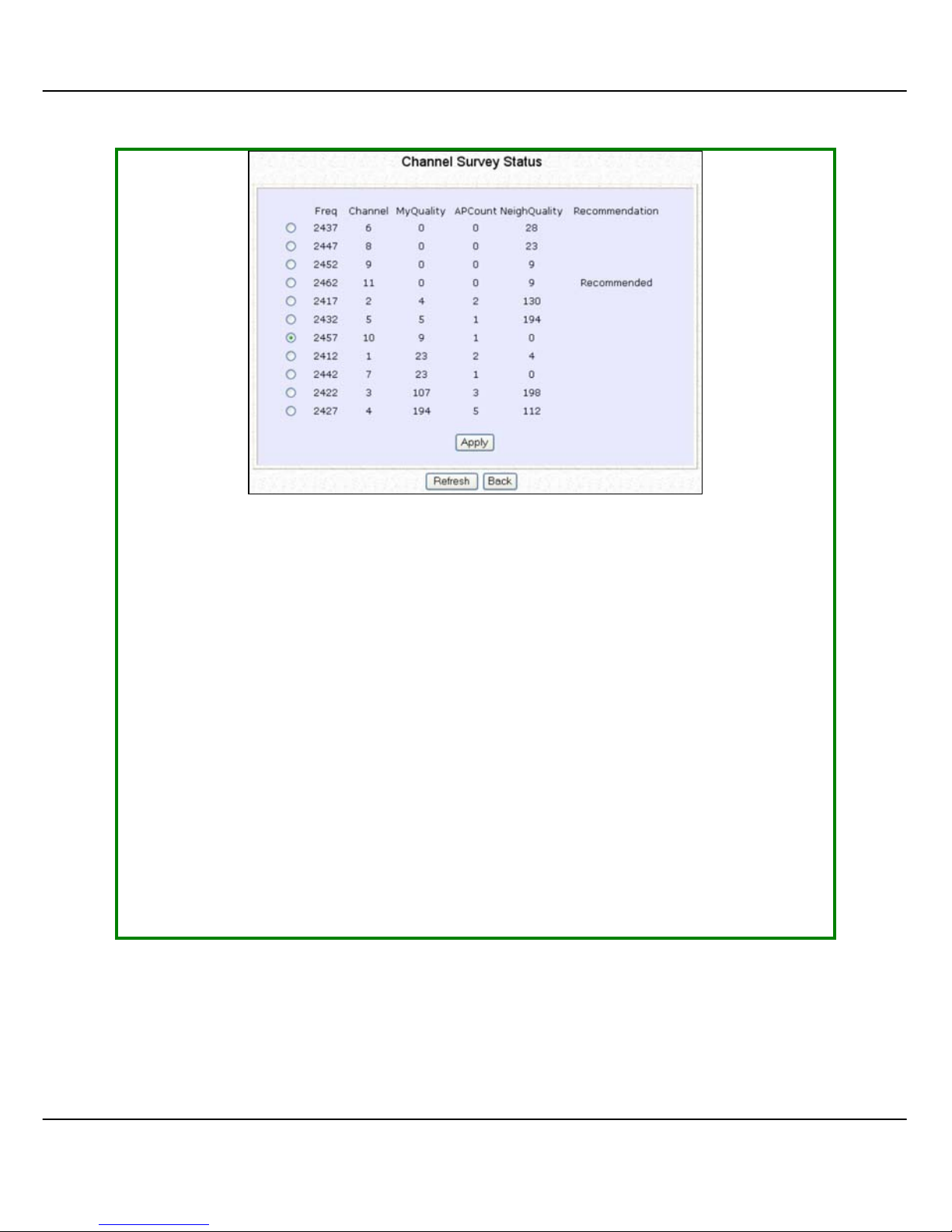
The CChhaannnneell SSuurrvveeyy provides a list of the FFrreeqq (frequency) and CChhaannnneell of
the access point detected, the AAPPCCoouunntt, MMyyQQuuaalliittyy (your access point’s
interference from your access point’s channel signal) received and
NNeeiig
g
hhQQuuaalliitty
y (interference from the neighbouring access points’ channel
signals) received.
Page 62
55
The values indicate the level of interference.
The higher the value, the higher the interference.
If the value is zero, there is no interference.
SStteepp 55::
To connect the WPP54GG-client to one of the channels detec ted, select the
radio button corresponding to the channel you want to connect to.
SStteepp 66::
Click on the AAppppllyy button to effect the change and return to the setup
page.
SStteepp 77::
Click on the RReeffrreesshh button to update this screen.
Page 63

56
This table describes the read-only parameters of all channels that can be
viewed from the Channel Survey page.
Parameters Description
Freq Refers to the frequency of the channel at which your
access point is operating.
Channel Refers to the channel of the access point bei ng used for
transmission depending on its origin of country.
MyQuality
Indicates the interference level of the respective channel
with this AP.
The lower the value, the less interference.
APCount Refers to the total numbe r of access points operating at
the current channel.
NeighQuality
Indicates the interference level with those discovered
APs at those respective channels.
The lower the value, the less interference.
Recommendation
Indicates the best channel for the AP device to use in its
current environment.
Page 64
57
A
A
NNTTEENNNNAA
A
A
LLIIGGNNMMEENNTT
(
(
AAVVAAIILLAABBLLEE
F
F
OORR
A
A
LLLL
M
M
OODDEESS
))
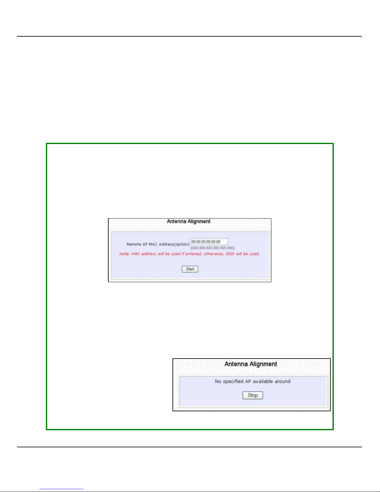
The Antenna Alignment feature in the access point is designed to precisely
align the antenna over such a long distance so that the connectivity
communication between your access point and another remote or
neighbouring access point could be improved as indicated by higher signal
strength.
SStteepp 11::
Click on WWLLAANN SSeettuupp from the CCOONNFFIIGGUURRAATTIIOONN menu. You wi ll see the sub-
menus expanded under WWLLAANN SSeettuupp. Click on AAnntteennnnaa AAlliiggnnmmeenntt. The
AAnntteennnnaa AAlliiggnnmmeennt
t page can act as a diagnostic tool to check the
communication with a remote device. The remote AP MAC Address is
preset to all zeros by default.
SStteepp 22::
If you wish to specify the MAC address of the remote AP , key in the field next
to RReemmoottee AAPP AAddddrreessss ((ooppttiioonn)), followed by executing the SSttaarrtt button. Then
the pop-up status screen will show up, allowing you to monitor the signal
strength received from the remote access points.
If there is no specified AP with
its MAC address you have
keyed in, the screen below will
show on the right. To abort or
key in the MAC address of the
other available remote AP,
click on the SSttoopp button.
Page 65
58
!
NOTE: To ensure pr oper functi onali ty of the device, selec t to
Stop after performing antenna alignm ent.
Alternativ ely, you may also reboot the device.
NOTE
If no MAC address is entered, the Antenna Alignment tool will
make use of the SSID to align the antenna. Please m ake sure that
the correct SSID is entered. If more than one access point (AP)
share the same SSID, the Antenna Alignment tool will show the
strongest signal AP.
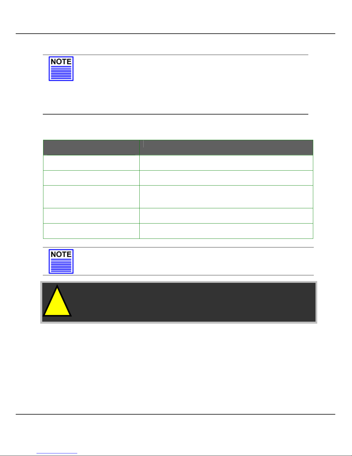
The DIAG LED indicates the signal strength as described below:
Signal Strength
(RSSI Value)
Status of DIAG LED
Above 20dBm Stays turned ON
Between 19 and 17 dBm
Flashes 6 times
Between 17 and 14 dBm Flashes 3 times
Between 13 and 10 dBm
Flashes ONCE
Below 10dBm Turns OFF
NOTE
The signal strength of below RSSI of 10 is not recommended for
outdoor long distance connection.
Page 66
59
T
T
OO CCOONNFFIIGGUURREE TTHHEE
S
S
EECCUURRIITTYY SSEETTUUPP OOFF TTHHEE WWIIRREELLEESSSS MMOODDE
E
Kindly refer to Chapter 5 on WLAN Security for details on setting the different
security modes of the access point.
T
T
OO CCOONNFFIIGGUURREE TTHHEE
A
A
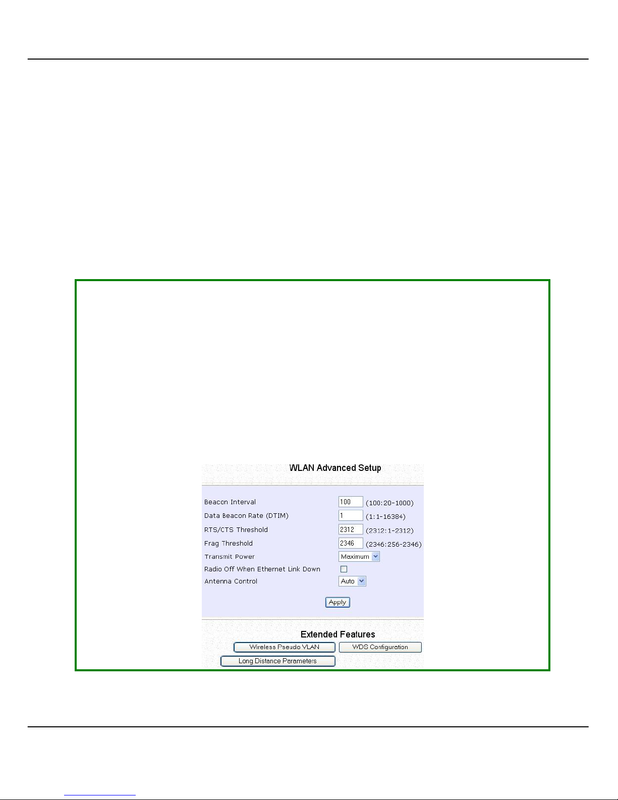
DDVVAANNCCEEDD SSEETTUUPP OOFF TTHHEE WWIIRREELLEESSSS MMOODDEE
The following will guide you to configure the advanced setup of the wireless
mode you have selected.
SStteepp 11::
Click on WWLLAANN SSeettuupp from the CCOONNFFIIGGUURRAATTIIOONN m enu to expand into the four
sub-menus. From here, click on AAddvvaanncceedd.
SStteepp 22::
In the WWLLAANN AAddvvaanncceedd SSeettuupp page, enter the parameters.
SStteepp 33::
Click on the AAppppllyy button to update the changes.
Page 67

60
This table describes the parameters that can be modified in the WWLLAANN
AAddvvaanncceedd SSeettuup
p page.
Parameters Description
Beacon Interval
(Only in Access
Point mode)
The Beacon Interval is the amount of time between
beacon transmissions. A beacon is a guidance signal
sent by the access point to announce its presence to
other devices in the network.
Before a client enters the power-sav e mode, it needs the
beacon interval to know when to wake up to receiv e the
beacon (and learn whether th ere are buffered frames at
the access point).
Data Beacon Rate
(DTIM)
(Only in Access
Point mode)
The Data Beacon Rate (DTIM) determines how often the
beacon contains a delivery traffic indication message
(DTIM). The DTIM identifies which clients (in power-save
mode) have data frames waiting for them in the access
point’s buffer.
If the beacon period is set at 100 (default value), and the
data beacon rate is set at 1 (default value), then the
access point sends a beacon containing a DTIM every
100 Kμsecs (1 Kμsec equals 1,024 μsec).
RTS/CTS Threshold The RTS/CTS Threshold value determi nes the minimu m size
of a packet in bytes that would trigger the RTS/CTS
mechanism.
Frag Threshold The Frag Threshold v alue indi cates the maxi mum si ze that
a packet can reach without being fragmented.
This value extends from 256 to 2346 bytes, where a value
of 0 indicates that all the packets should be transmitted
using RTS.
Transmit Power The Transmit Power drop-down list lets you pick from a
range of transmission power.
Radio Off When
Ethernet Link
Down
The Radio Off When Ethernet Link Down function detects
when the Ethernet link is down and disables the radio card
automatically.
Page 68
61
Antenna Control
The Antenna Control function allows you to control whether to
use the:
• External antenna (Default)
• Internal antenna
NOTE
The values illustrated in the examples are suggested values for
their respective parameters.
S
S
TTAATTIISSTTIICCS
S
The following shows you the information on the wireless device that is
connected to the WLAN.
I
I
NN
A
A
CCCCEESSSS
P
P
OOIINNTT MMOODDE
E
SStteepp 11::
Click on WWLLAANN SSeettuupp from the CCOONNFFIIGGUURRAATTIIOONN menu. You will see the sub-
menus expanded under WWLLAANN SSeettuupp. Click on SSttaattiissttiiccss.
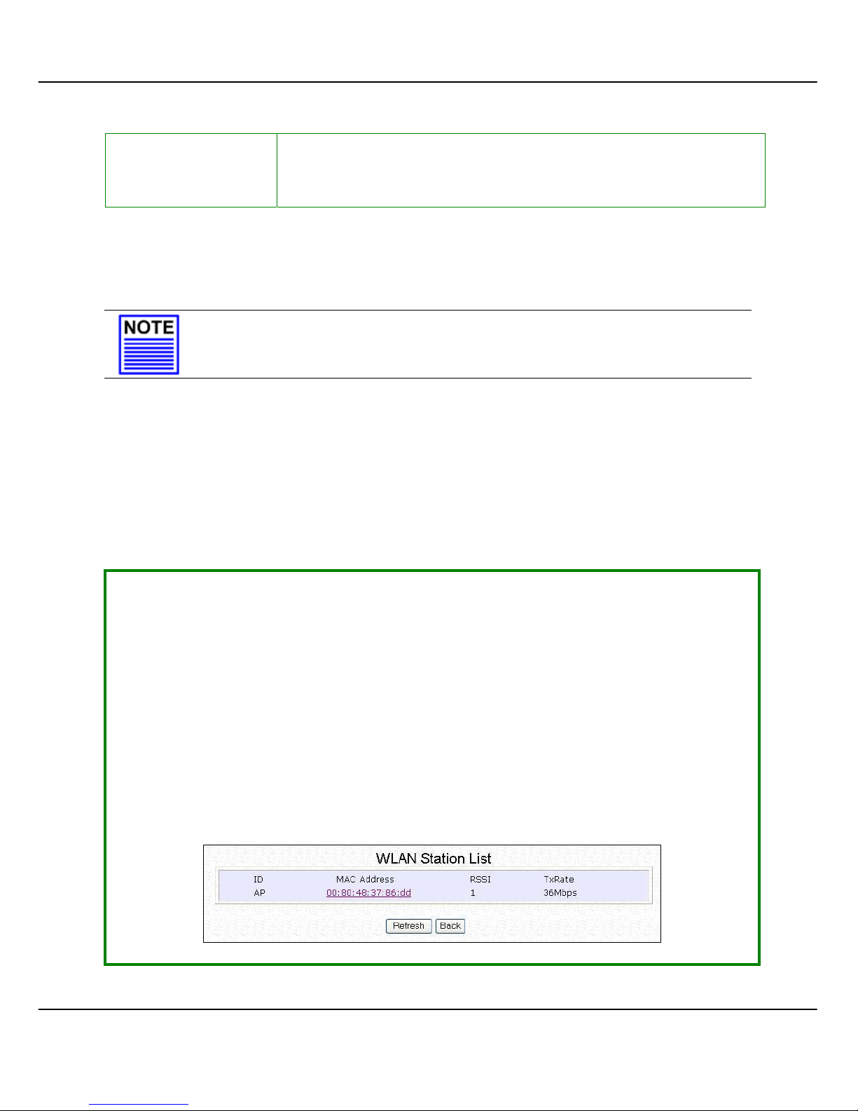
Wireless clients that are connected to the WLAN are shown in the WLAN
Station List.
SStteepp 22::
Click on the RReeffrreesshh button to get the lates t information on the avai lability of
wireless clients in the wireless network.
Page 69
62
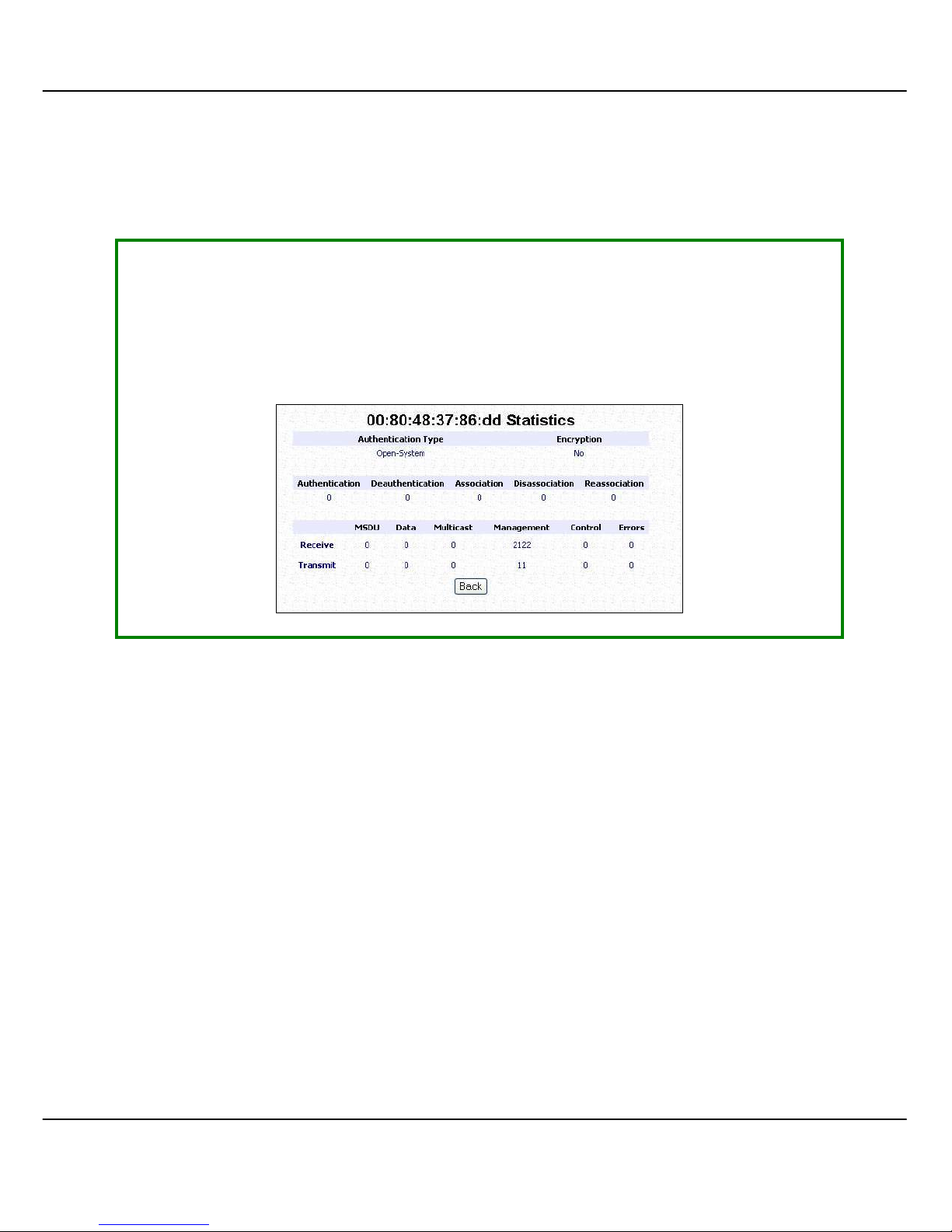
SStteepp 33::
To check the details on individual wirel ess client, click on the MAC Address in
the WLAN Station List.
The following screen will show the statistics of the selected wireless client.
Page 70
63
I
I
NN
C
C
LLIIEENNTT MMOODDE
E
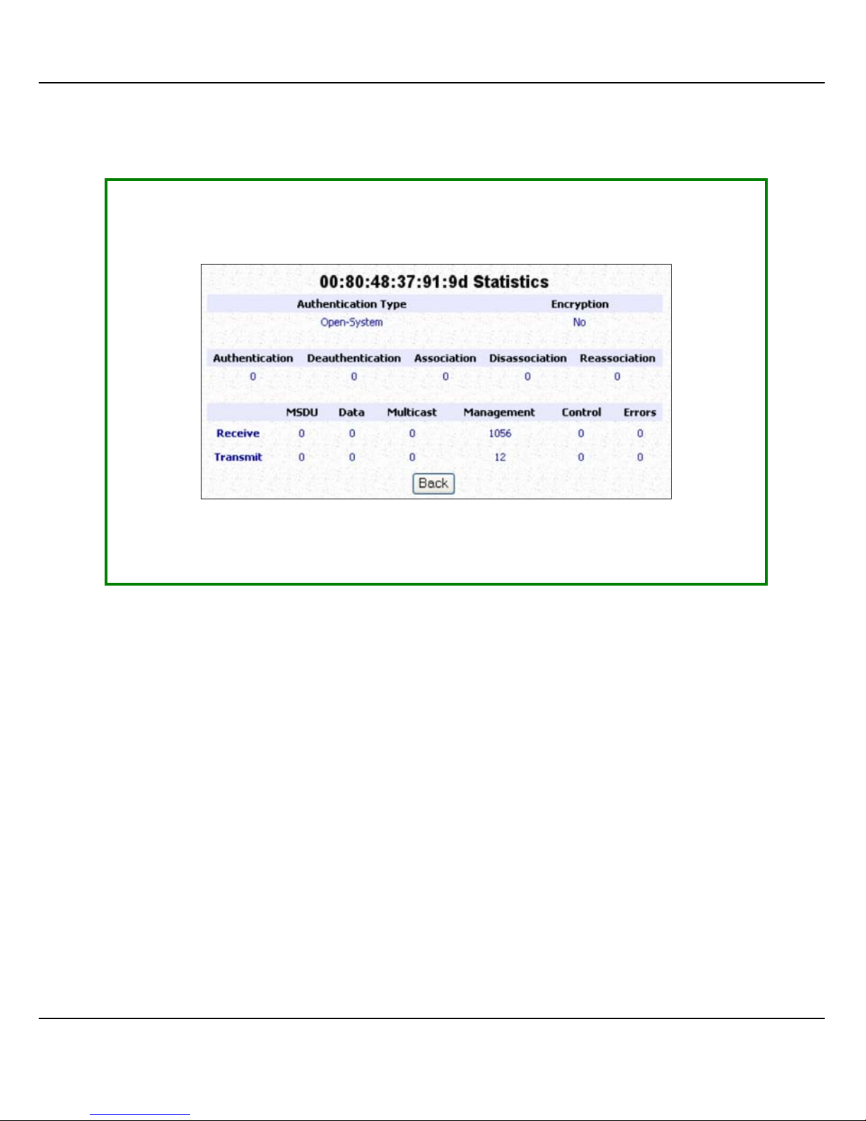
Click on WWLLAANN SSeettuupp from the CCOONNFFIIGGUURRAATTIIOONN menu. You will see the sub-
menus expanded under WWLLAANN SSeettuupp. Click on SSttaattiissttiiccss.
In CClliieenntt mode, you are not allowed to vi ew other wirel ess clients’ sta tistics. To
view other wireless clients information, you need to change to Access Point
mode.
Page 71
64
I
I
NN
W
W
IIRREELLEESSSS
R
R
OOUUTTIINNGG
C
C
LLIIEENNT
T
,, W
W
IIRREELLEESSSS
A
A
DDAAPPTTEER
R
,,
AANNDD
T
T
RRAANNSSPPAARREENNTT
C
C
LLIIEENNTT
M
M
OODDEES
S
Click on WWLLAANN SSeettuupp from the CCOONNFFIIGGUURRAATTIIOONN menu. You will see the sub-
menus expanded under WWLLAANN SSeettuupp. Click on SSttaattiissttiiccss.
Page 72
65
I
I
NN
G
G
AATTEEWWAAYY MMOODDE
E
Click on WWLLAANN SSeettuupp from the CCOONNFFIIGGUURRAATTIIOONN menu. You will see the sub-
menus expanded under WWLLAANN SSeettuupp. Click on SSttaattiissttiiccss.
To view the statistics informati on if a wireless client connec ted to the AP, click
on the MAC address of that client.
Page 73
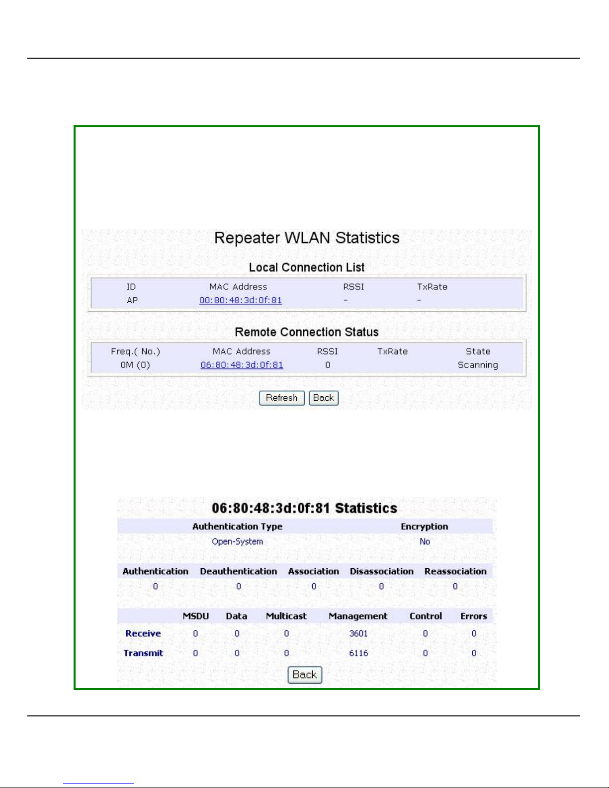
66
I
I
NN
R
R
EEPPEEAATTEERR MMOODDE
E
Click on WWLLAANN SSeettuupp from the CCOONNFFIIGGUURRAATTIIOONN menu. You will see the sub-
menus expanded under WWLLAANN SSeettuupp. Click on SSttaattiissttiiccss.
Click on the RRee
ffrreessh
h button to get the latest informati on on the wireless clients
in the wireless network.
To check the details on individual wirel ess client, click on the MAC Address in
the lists.
The following screen will show the statistics of the selected wireless client.
Page 74
67
WWAANN S
S
EETTUUP
P
(only supported by Wireless Routing Client and Gateway)
A correct WAN Setup allows you to successfully share your Internet connection
among the wired and wireless clients of the access point. To do so, you need to
identify the type of broadband I nternet access you are subscribed to. If you are
using :
• Cable Internet where your ISP dynamically assigns a WAN IP address to you,
refer to WAN Setup - Cable Internet with Dynamic I P Assignment.
• Cable Internet where your ISP provides you with a fixed WAN IP address (or
a range of fixed IP addresses), refer to WAN Setup - Cable Internet with
Static IP Assignment.
• ADSL Internet that requires standard PPP over Ethernet (PPPoE) for
authentication , refer to WAN Setup - ADSL Internet using PP P over Ethernet
(PPPoE).
• ADSL Internet that requires standard Point-to-Point Tunneling Protocol (PPTP)
for authenticati on, refers to WAN Setup – ADSL Intern et using Point-to-Point
Tunneling Protocol (PPTP).
WAN Setup - Cable Internet with Dynamic IP Assignment
The access point is pre-configured to support a WAN type that dynamically
obtains an IP address from the ISP. However, you may verify the WAN settings with
the following steps:
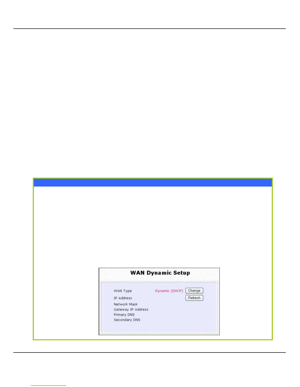
SStteepp 11:: UUnnddeerr CCOONNFFIIGGUURRAATTIIOONN oonn tthhee ccoommmmaanndd mmeennuu,, c
clliicckk
oonn WWAANN SSeettuupp..
SStteepp 22::
On the WWAANN DDyynnaammiicc SSeettuupp screen that follows, veri fy that the WWAANN TTyyppee reads
DDyynnaammiicc ((DDHHCCPP)
) in red colour. Otherwise, click on the CChhaannggee button.
Page 75
68
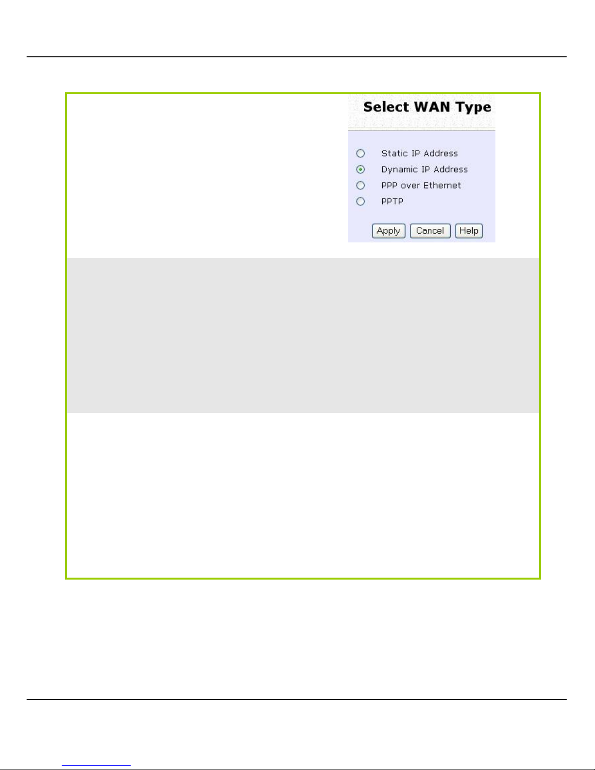
Step 3:
Simply select DDyynnaammiicc IIPP AAddddrreessss
and hit the AAppppllyy button.
Please remember to click RReebboooott
SSyysstteem
m under SSYYSSTTEEMM TTOOOOLL
S
S and hit
the RReebboooott button to let the setting s
take effect.
Note:
Additional configuration might be required before your ISP will allocate an IP
address to the access point.
Certain ISPs require authentication through a DHCP Client ID before releasing a
public IP address to you. The access point uses the System Name in the System
Identity as the DHCP Client ID.
Therefore, if this is the case, refer to your ISP for the correct DHCP Client I D
to be set and follow steps 4 - 5 to accomplish the setup.
SStteepp 44::
Steps 4 - 5 are for those who need to
set up the SSyysstteemm NNaammee in SSyysstteemm
IIddeennttiitty
y so that your ISP can
authenticate it as a valid DHCP Client
ID.
Click on SSyysstteemm IIddeennttiittyy under the
SSYYSSTTEEM
M
TTOOOOLLS
S command menu.
Page 76

69
Step 5:
On the following screen, key in the
your ISP assigned DHCP Client ID as
the SSyysstteemm NNaammee (You may also like
to key in a preferred SSyysstteemmss CCoonnttaacctt
person and the SSyysstteemm LLooccaattiioonn of
the access point). Click the AAppppllyy
button to complete.
Please remember to click RReebboooott
SSyysstteem
m under SSYYSSTTEEMM TTOOOOLLSS and hit
the RReebboooott button to let the settings
take effect.
Page 77
70
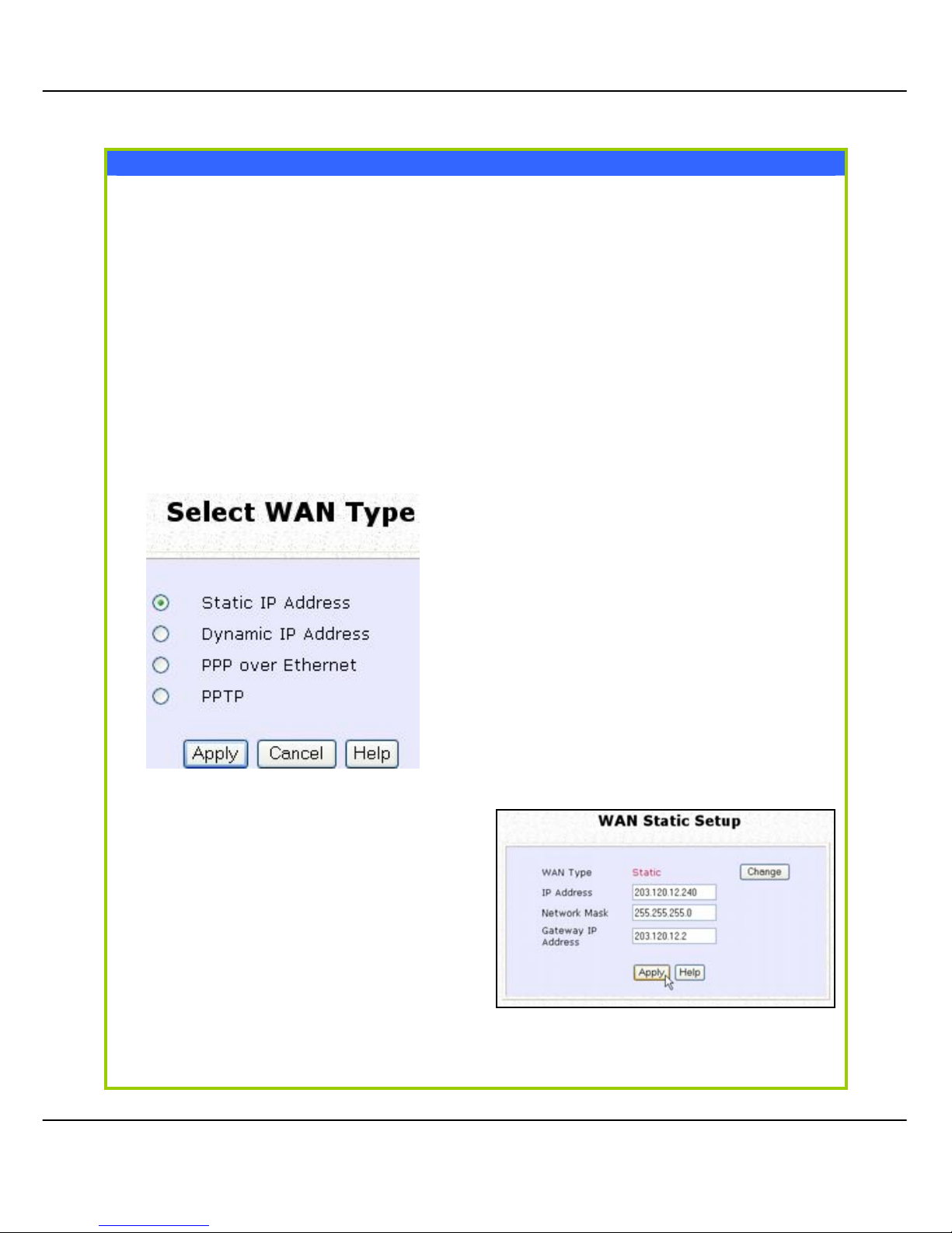
WAN Setup - Cable Internet with Static IP Assignment
If you have an ISP that leases a sta ti c WAN IP for your subscri pti on, you will need
to configure your access point’s WAN type accordingly. For example, if the ISP
provided you with the following setup i nformation , you can set up your WAN as
described below:
IP Address : 203.120.12.240
Network Mask : 255.255.255.0
Gateway IP Address : 203.120.12.2
Step 1:
Under CCOONNFFIIGGUURRAATTIIOONN on the command menu, click on WWAANN SSeettuupp.
Step 2:
Access the SSeelleecctt WWAANN TTyyppee page
and choose SSttaattiicc IIPP AAddddrreessss before
clicking the AAppppllyy button. You will
then be brought to the following
page requiring your inputs.
Step 3:
Fill in the information provided by
your ISP in the IIPP AAddddrreessss,, NNeettwwoorrkk
MMaassk
k and GGaatteewwaayy IIPP AAddddrreessss
fields, before clicking the AAppppllyy
button.
Please remember to click RReebboooott
SSyysstteem
m under SSYYSSTTEEMM TTOOOOLLSS and hit
the RReebboooott button to let the settin gs
take effect.
Page 78
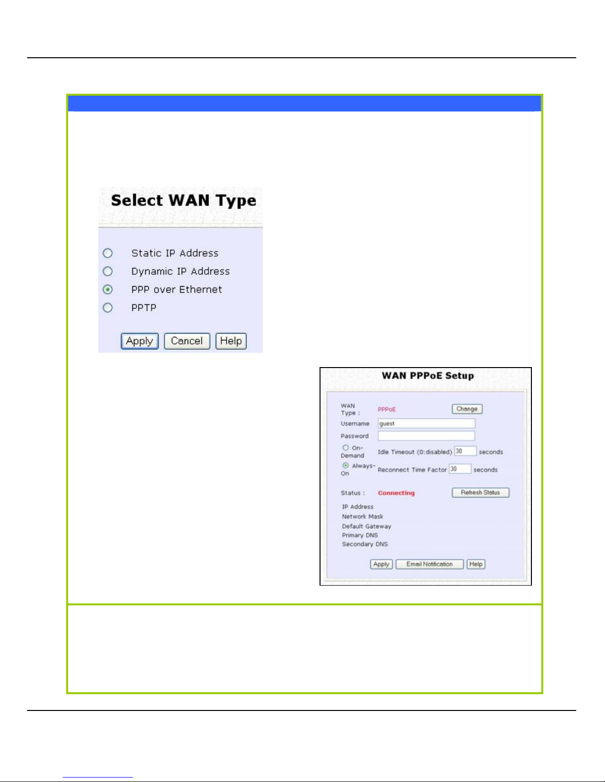
71
WAN Setup - ADSL Internet using PPP over Ethernet (PPPoE)
If you subscribe to an ADSL service using PPP over Ethernet (PPPoE)
authentication, you can set up your access point’s WAN type as follows. For
example, you may configure an account whose username is ‘guest’ as
described below:
Step 1:
Under CCOONNFFIIGGUURRAATTIIOONN on the
command menu, click on WWAANN SSeettuupp.
Step 2:
Access the SSeelleecctt WWAANN TTyyppee page
and choose PPPPPP oovveerr EEtthheerrnneett before
clicking the AAppppllyy button. You will
then be brought to the following
page requiring your inputs.
Step 3:
For UUsseerrnnaammee, key in your ISP
assigned account name (e.g. guest
for this example), followed by your
account PPaasssswwoorrdd.
Step 4:
Select AAllwwaayyss--OOnn if you want your
access point to always maintain a
connection with the ISP. Otherwise,
you may select OOnn--DDeemmaanndd. The
access point will then c onn ect to the
ISP automatically when it receives
Internet requests from the PCs in your
network.
The IIddllee TTiimmeeoouutt setting is associated with the OOnn--DDeemmaanndd option, allowing you
to specify the value (in seconds) after which the access point will disconnect
from the ISP after the last I nter ne t ac ti vity. A value of “0” will di sabl e idl e timeout.
RReeccoonnnneecctt TTiimmee FFaaccttoor
r is associated with the AAllwwaayyss
--oon
n option and specifies
the maximum time the access poi nt will wait before re-attempting to connect
with your ISP. Hit the AAppppllyy button and RReebboooott the access point.
Page 79
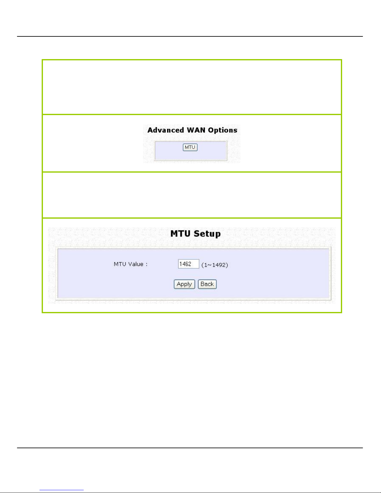
72
You can limit the maximum size a packet can be in a network by setting the MMTTUU
(Maximum Transmissible Unit).
Click the MMTTUU Button in AAddvvaanncceedd WWAANN OOppttiioonnss.
The MMTTUU VVaalluuee has a range of 1 to 1492.
Enter the MMTTUU VVaalluuee and click AAppppllyy.
Page 80
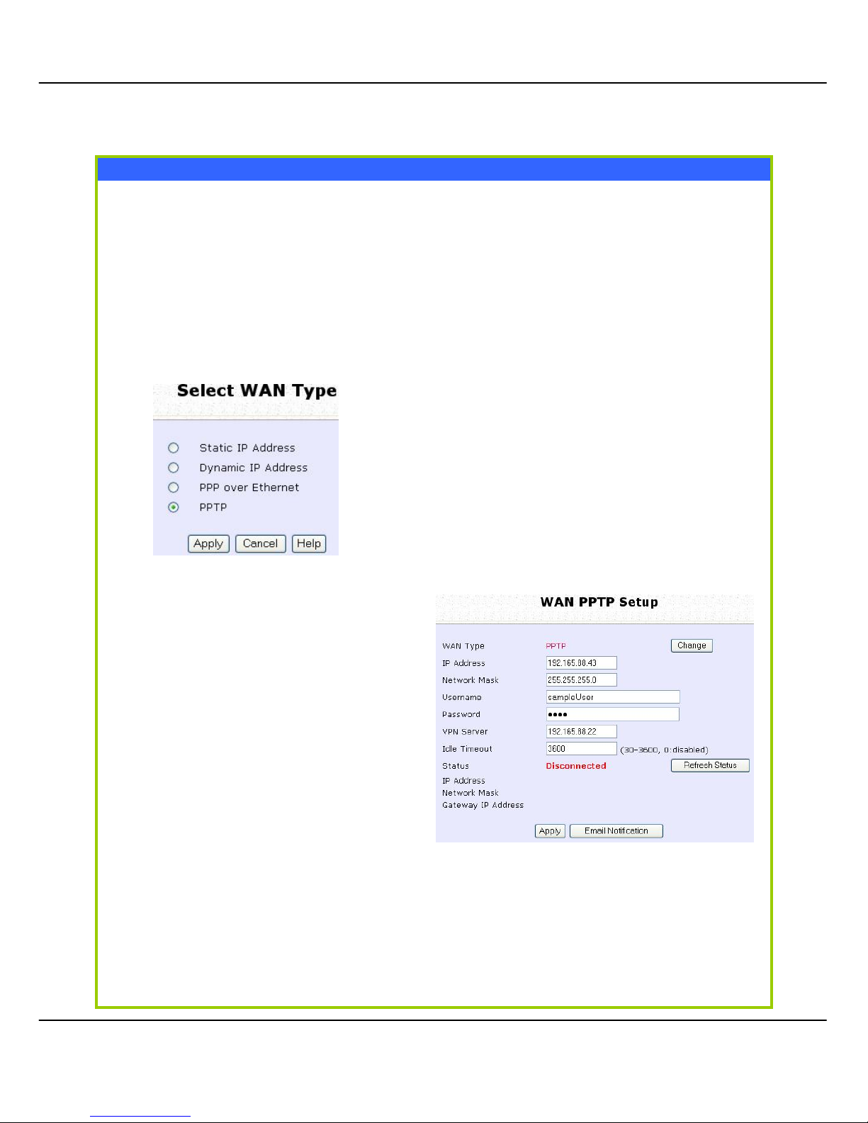
73
WAN Setup – ADSL Internet using PPTP
If you subscribe to an ADSL serv ic e usi ng Point-to-Point Tunneling Protocol (PPTP)
authentication, you can set up your access point’s WAN type from the steps
that follow. For example, if the ISP provided you with the following set up
information, you can set up your WAN as described below:
IP Address : 203.120.12.47
Network Mask : 255.255.255.0
VPN Server : 203.120.12.15
Step 1:
Under CCOONNFFIIGGUURRAATTIIOONN on the command menu, click on WWAANN SSeettuupp.
Step 2:
Access the SSeelleecctt WWAANN TTyyppee page and
choose PPPPTTPP before clicking the AAppppllyy
button. You will then be brought to the
following page requiring your inputs.
Step 3:
Fill in the information provided by
your ISP in the IIPP AAddddrreessss,,
NNeettwwoorrkk MMaassk
k, VVPPNN SSeerrvveerr, and
DDHHCCPP
fields, followed by clicking
the AAppppllyy button.
Please remember to click RRee
b
boooott
SSyysstteem
m under SSYYSSTTEEMM TTOOOOLLSS and
hit the RReebboooott button to let the
settings take effect.
The IIddllee TTiimmeeoouutt setting allows
you to specify the value (in
seconds) after which the access
point will disconnect from the ISP
after the last Internet activity. A
value of “0” will disable idle
timeout.
Page 81
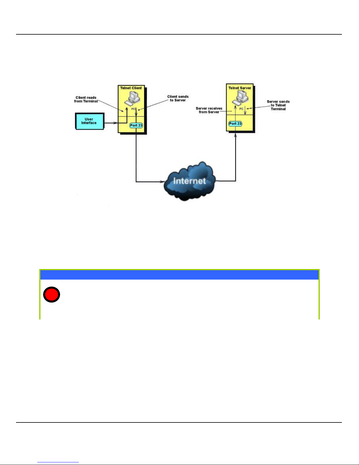
74
T
T
EELLNNEET
T
//SSSSHH S
S
EETTUUP
P
Telnet allows a computer t o remotely connect to the NetPassage WPP54GG CLI
(Command Line Interface) for control and monitoring.
SSH (Secure Shell Host) establishes a secure host conn ection to the NetPassage
WPP54GG CLI for control and monitoring.
Telnet/SSH Setup
Click Telnet/SSH Setup from the CONFIGURATION menu.
1
Page 82
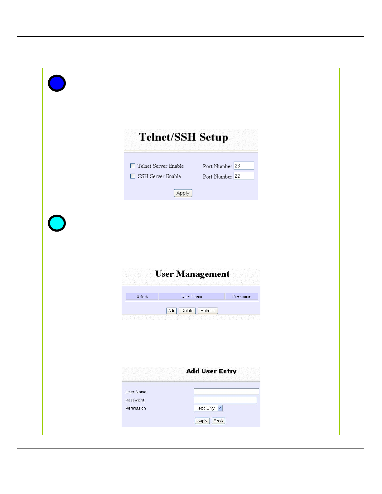
75
1. To enable Telnet Server: Select Telnet Server Enable and enter the Port Number.
2. To enable SSH server: Select SSH Server Enable and enter the Port Number.
Click Apply.
To add user:
1. Click Add button.
2. In Add User Entry Page, enter User Name, Password, and specify whether user is
granted permission to Read Only or Read/Write.
3. Click Apply.
2
3
Page 83
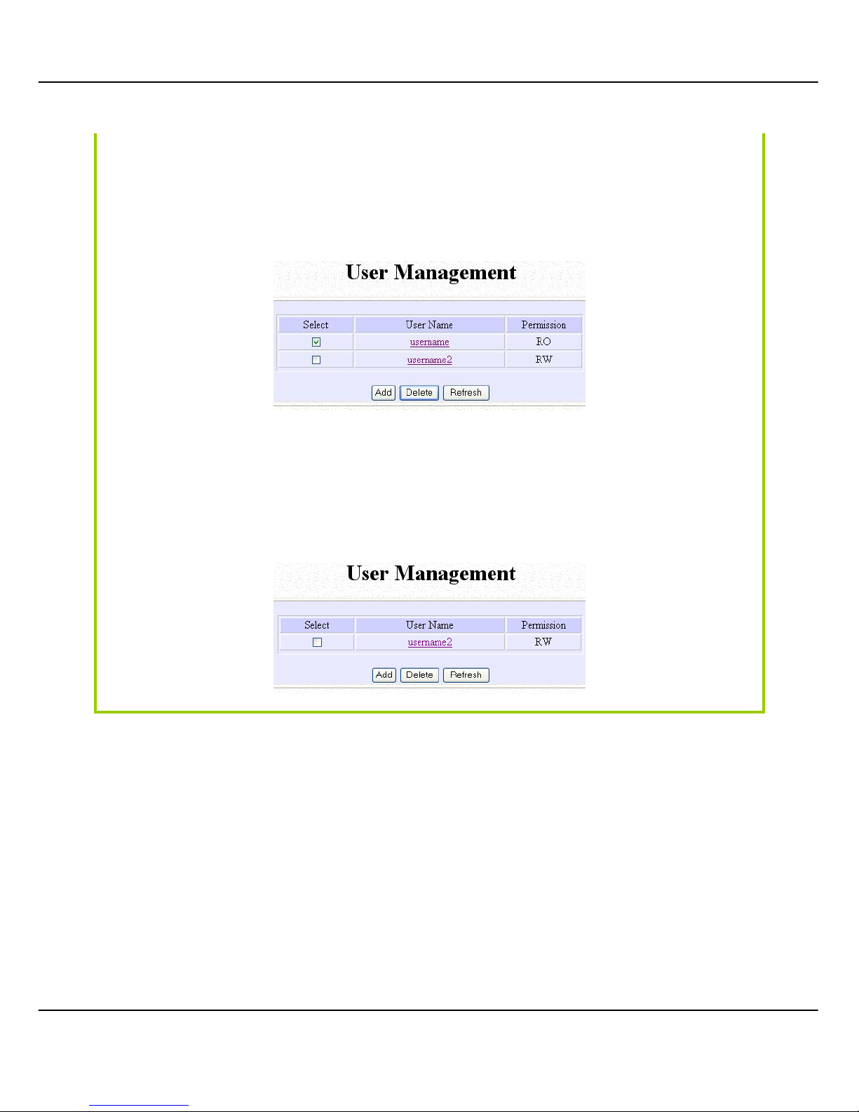
76
To Dele te User:
1. Select which user to Delete.
2. Click Delete.
User Management list refreshes to update users.
To Refresh User Management list:
Click Refresh to refresh User Management list.
Page 84
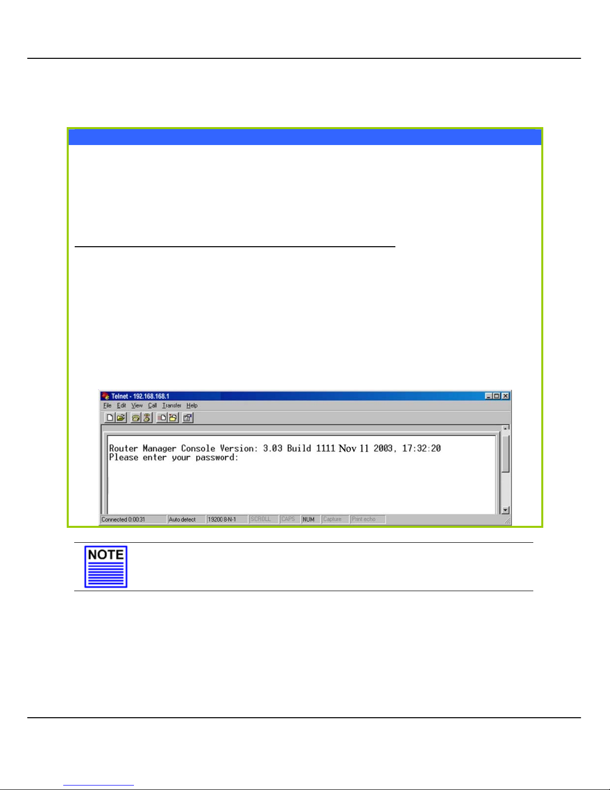
77
TTEELLNNEETT C
C
OOMMMMAANNDD
L
L
IINNEE
I
I
NNTTEERRFFAACCE
E
Telnet CLI (Command Line Interface)
The user may connect to the CLI (Command Line I nter face ) vi a a TELNE T sessi on
to the default IP, 192.168.168.1. This section uses Microsoft TELNET command for
instruction. You may use any TELNET client.
Connecting to CLI (Command Line Interface) via TELNET
1. Connect to CLI (Command Line Interface) with the following
command at DOS prompt. The TELNET application will then be launched and
connected.
C:\WINDOWS\TELNET 192.168.168.1
2. At the login prompt, type in “password” (default password) and press
the <ENTER> key, as shown in Figure 2.4c. You will then login to the CLI.
NOTE
Please refer to Appendix IV for the list of commands available at
the console.
Page 85
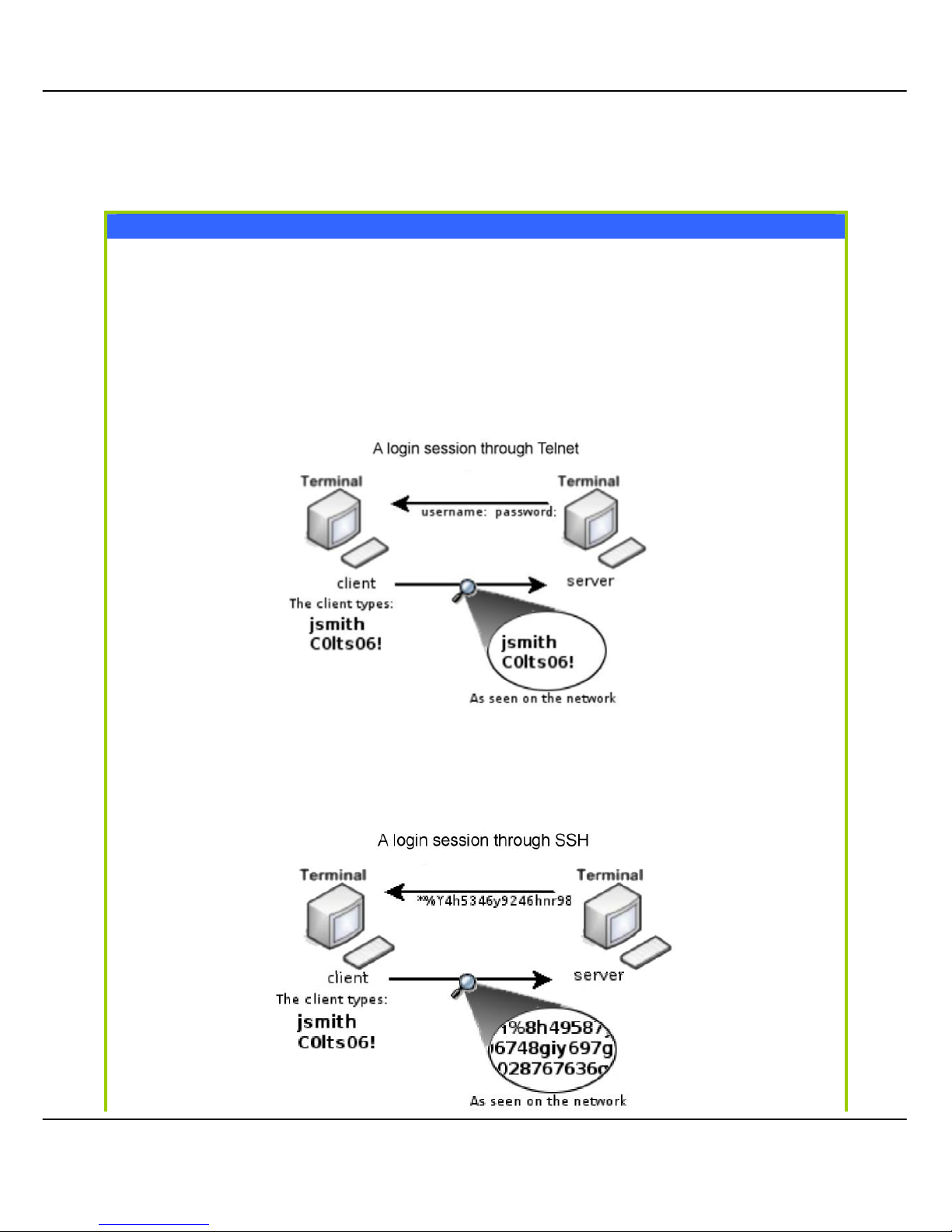
78
SSSSHH C
C
OOMMMMAANNDD
L
L
IINNEE
I
I
NNTTEERRFFAACCE
E
SSH CLI (Secure Shell Host Command Line Interface)
SSH is designed and created to provide the best security when
accessing another computer remotely. Not only does it encrypt the
session, it also provides better authentication facilities and features that
increase the security of other protocols. It can use different forms of
encryption and ciphers.
The first diagram below shows a telnet session.
The second diagram below shows how an encrypted connection like
SSH is not viewable on the network. The server still can read the
information, but only after negotiating the encrypted session with the
client.
Page 86
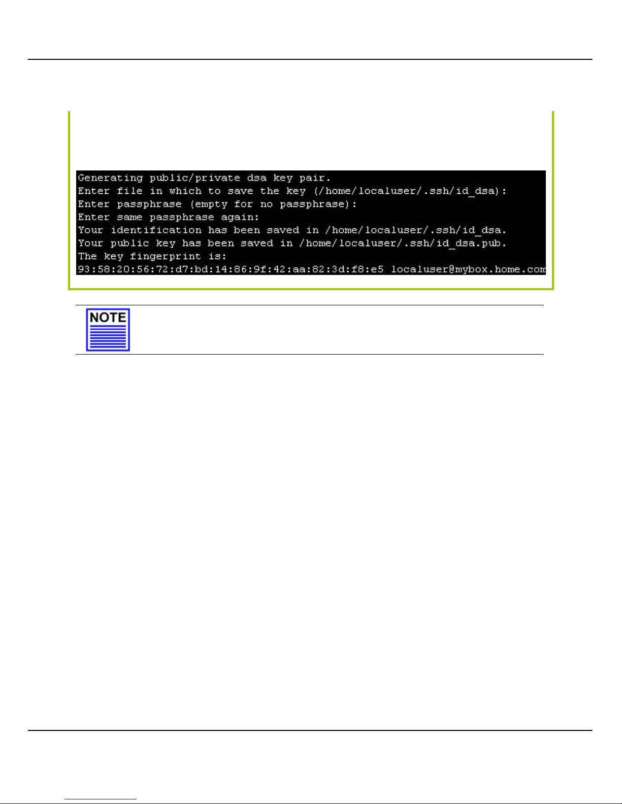
79
SSH CLI has a command line interface like shown below for example.
NOTE
Please refer to Appendix V for the list of commands available a t
the console.
Page 87
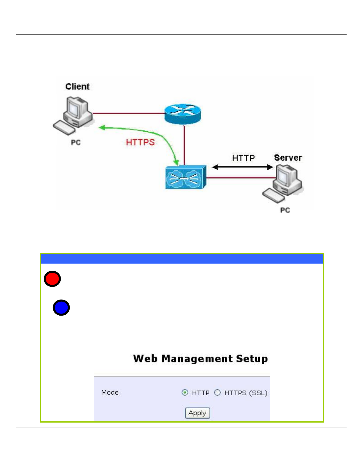
80
W
W
EEBB
M
M
AANNAAGGEEMMEENNTT
S
S
EETTUUP
P
NetPassage WPP54G supports HTTPS (SSL) in addition to the standard HTTP.
HTTPS (SSL) features additional authentication and encryption for secure
communication.
Web Management Setup
Select Web Management Setup from the CONFIGURATION menu.
1. Select whether to set web server to HTTP or HTTPS (SSL) mode.
2. Click Apply.
Changes will be effected after reboot.
1
2
Page 88
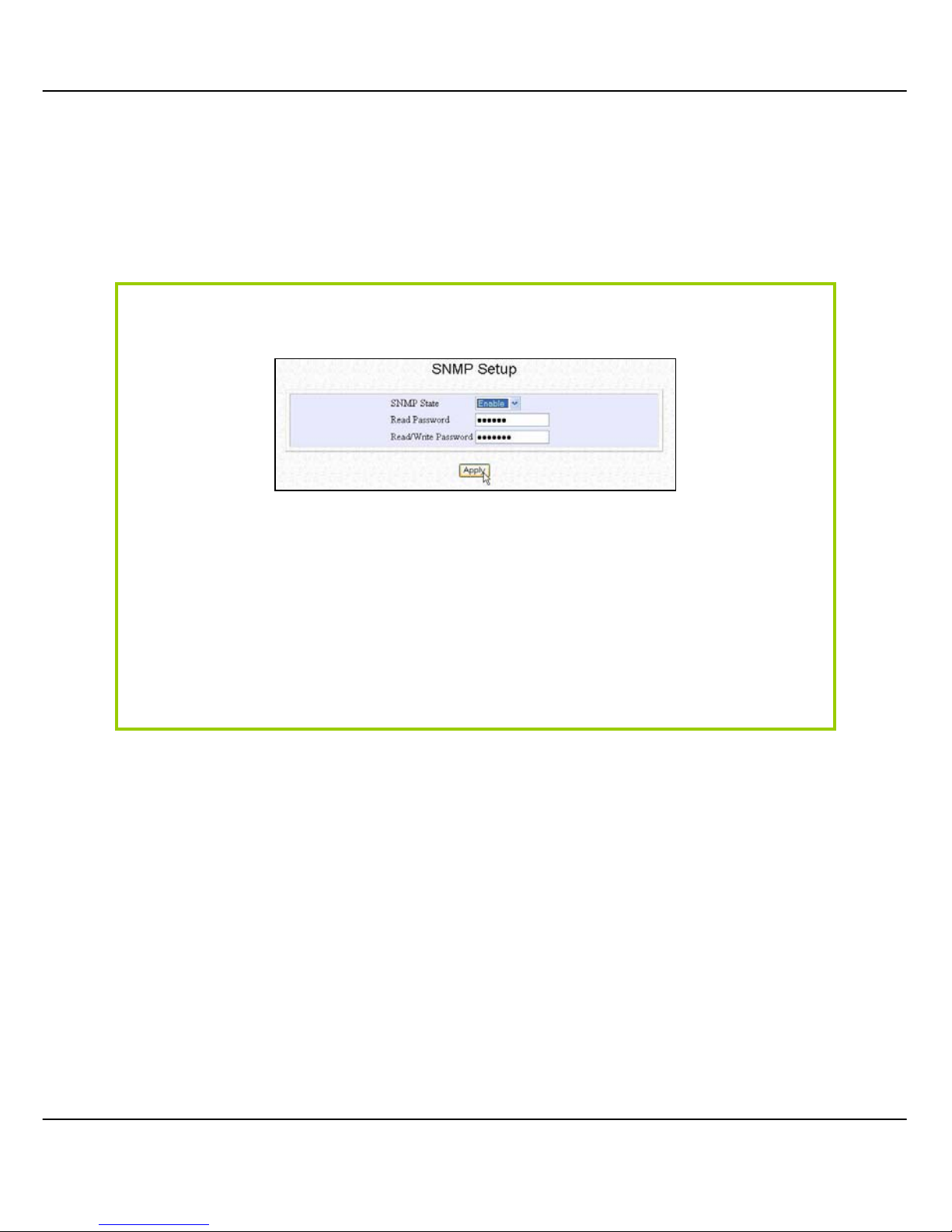
81
SSNNMMPP S
S
EETTUUP
P
Simple Network Management Protocol (SNMP) is a set of communication
protocols that separates the management architecture from the architecture
of the hardware devices.
Step 1:
Click on SSNNMMPP from the CCOONNFFIIGGUURRAATTIIOONN menu.
Step 2:
Select EEnnaabbllee from the SSNNMMPP SSttaattee drop-down list.
The default RReeaadd PPaasssswwoorrdd is set to public while the default RReeaadd//WWrriittee
PPaasssswwo
orrdd is private.
Step 3:
Click on the AAppppllyy button.
Page 89
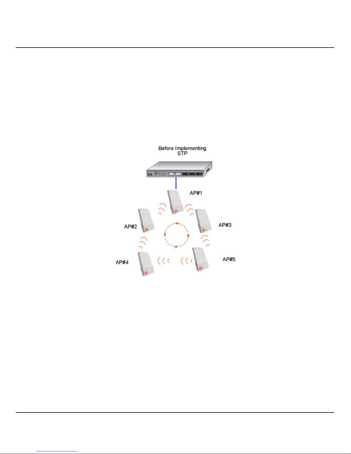
82
SSTTPP S
S
EETTUUPP
(Only available in Access Point, Transparent Client, and Repeater Modes)
Spanning Tree Protocol (STP) is a link management
protocol that helps to
prevent undesirable loops occurs in the network. For an Ethernet network to
function properly, only one active path can exist between two stations. If a
loop exists in the network topol ogy, duplication of messages will occur and this
might confuse the forwarding algorithm and allow duplicate frames to be
forwarded.
In short, the main purpose of activating STP is to prevent looping when you
have redundant paths in the network. Without activating STP, redundant
topology will cause broadcast storming.
To establish path redundancy, STP creates a
tree that spans all of the devices in
an extended network, forcing redundant paths into a standby, or blocked,
state, but establishing the redundant links as a backup in case the active link
should fail. If STP costs change, or if one network segment in the STP becomes
unreachable, the spanning tree algorithm reconfigures the spanning tree
topology and re-establishes the connection by activating the standby path.
Without spanning tree in place, it is possible that more than one connection
may be simultaneously live, which could result in an endless loop of traffic on
the
LAN.
Page 90
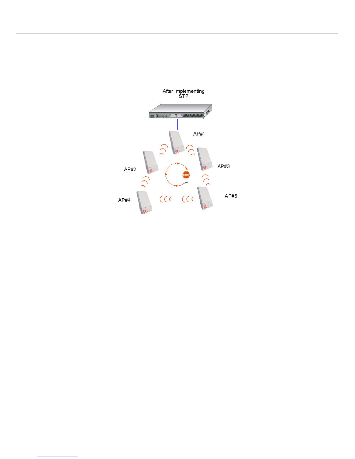
83
Spanning-Tree Protocol operation is transparent to end stations, which are
unaware whether they are connec ted to a single LAN segment or a switched
LAN of multiple segments.
The path with the smallest cost wil l be used and extra redundant paths will be
disabled.
To explain the effect of STP on the wireless clients , we will compare 2 separate
scenarios.
Page 91
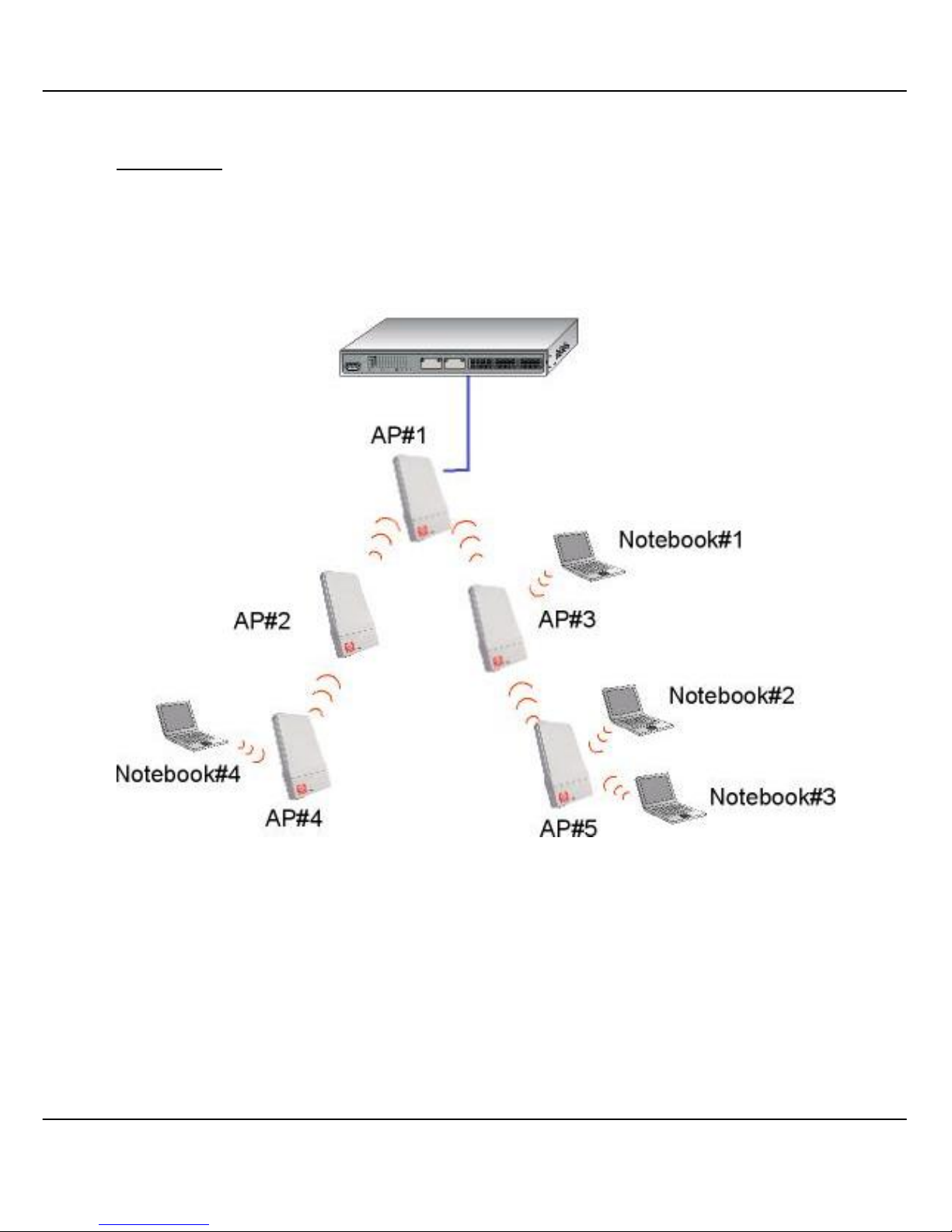
84
Scenario #1 – (No STP)
Referring to the illustration below, if the Spanning Tree Protocol (STP) is not
implemented in a network, all clients (Notebook#1 , #2, #3 & #4,) can access to
one another, resulting in low level of data security. Due to the redundant paths
found in this network, broadcast packets will be duplicated and forwarded
endlessly resulting in a broadcast storm.
Page 92
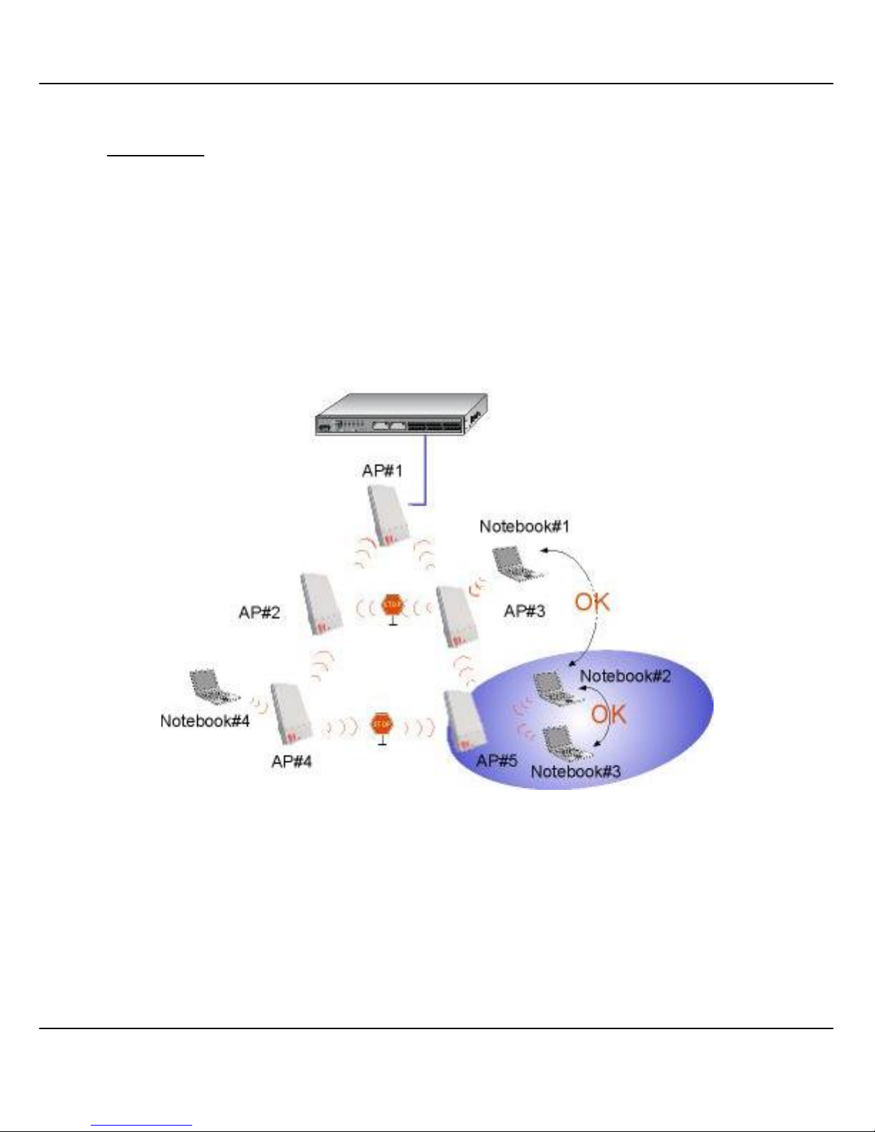
85
Scenario #2 – (With STP)
When STP is enabled, extra redundant network paths between APs will be
disabled, hence preventing multi ple active network paths in-between any two
APs.
If one of the APs is down, the STP algorithm will reactivate one of the redundant
paths so that the network connection will not be lost.
All wireless users will be able to communicate with each other if they are
associated to the APs that are in the same zone.
Page 93
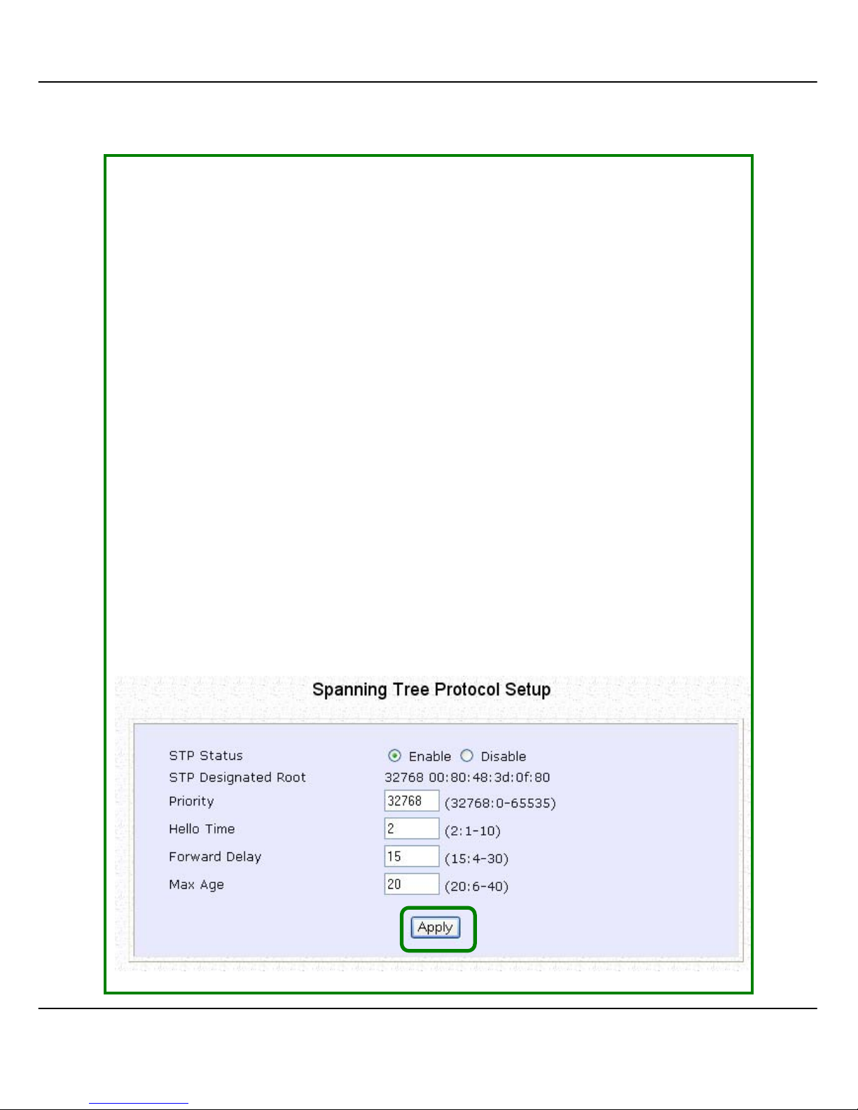
86
SStteepp 11::
Click on SSTTPP SSeettuupp from the CCOONNFFIIGGUURRAATTIIOONN menu.
SStteepp 22::
Select EEnnaabbllee from the SSTTPP SSttaattuuss radio button. Fill in the fields, and cli ck on
the AAppppllyy button to update the changes.
Priority: (Default: 32768, Range: 0 – 65535)
This is the relative priority.
The lowest priority will be elected as the root.
Hello Time: (Default: 2, Range: 1 – 10)
This is the hello time.
Every (this number) seconds, a hello packet is sent out by.
Hello packets are used to communicate information about the topology
throughout the entire STP network.
Forward Delay: (Default: 15, Range: 4 – 30)
The forward delay is the time that is spent i n the listening and learning state.
Max Age: (Default: 20, Range: 6 – 40)
The max age timer control s the m aximum length of time that pass es befor e a
port saves its configuration information.
Page 94

87
MMAACC F
F
IILLTTEERRIINNG
G
MAC Filtering acts as a securi ty measure by controlling the users accessing to
the network through their MAC address. Each WLAN or radi o card supports up
to 16 virtual access points and has i ts own MAC address listing. The client MAC
addresses entries can be set apply to all, or to only selected virtual access
points.
!
NOTE: MAC Filtering will not filter any MAC address
from Ethernet port.
Page 95
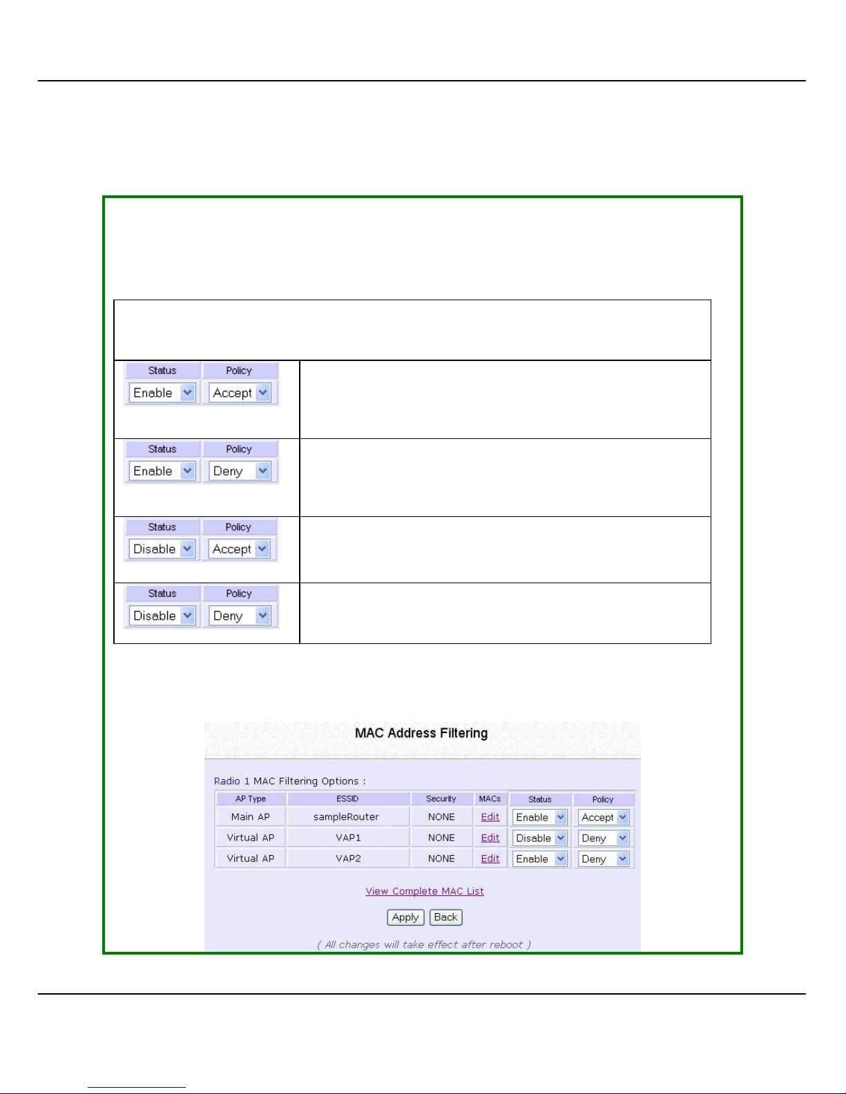
88
A
A
DDDD AA
MMAACC
AADDDDRREESSSS TTOO TTHHEE
MMAACC A
A
DDDDRREESSSS
L
L
IISST
T
..
SStteepp 11::
Select MMAACC FFiilltteerriinngg from WWLLAANN SSeettuupp((aa//bb//gg)).
MAC Address Filtering page displays.
In this page you may also set the MAC Filtering Status to EEnnaabbllee or DDiissaabbllee
for access points and set the Policy to either AA
cccceepptt
or DDeennyy MAC
addresses.
MAC Filtering set to EEnnaabbllee with Policy to AAcccceepptt
only the MAC addresses in the MAC Filter Address
List and deny all other MAC addresses.
MAC Filtering set to EEnnaabbllee with Policy to DDeennyy all
the MAC addresses in the MAC Filter Address List
and accept all other MAC addresses.
MAC Filtering set to DDiissaabbllee. Whether Policy is set to
EEnnaabblle
e or DDeennyy does not matter.
MAC Filtering set to DDiissaabbllee. Whether Policy is set to
EEnnaabblle
e or DDeennyy does not matter.
Click EEddiitt.
(This displays the MAC Address List of individual virtual access points.)
Page 96
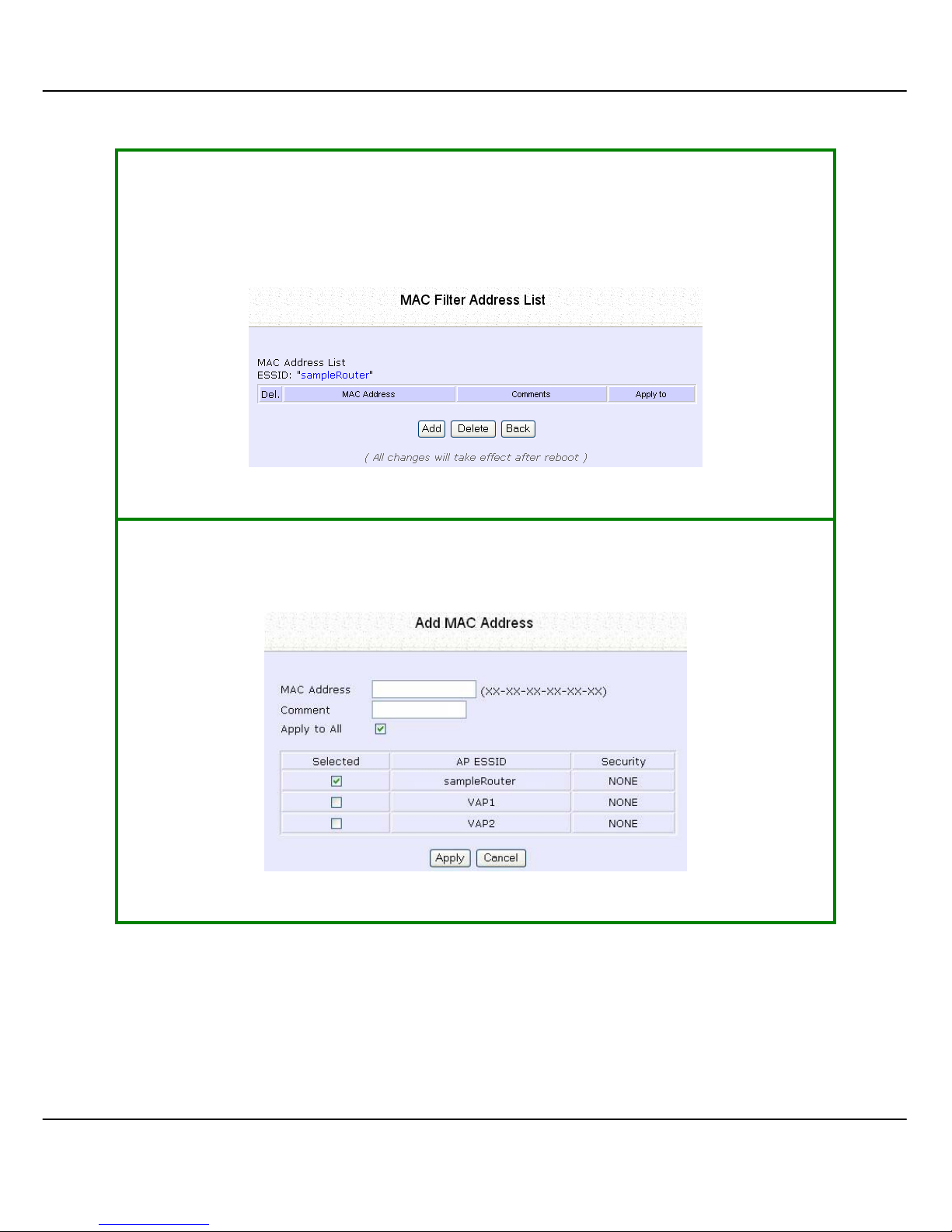
89
SStteepp 22::
MAC Filter Address List page displays.
Click the AAdddd button.
SStteepp 33::
Add MAC Address page displays.
Page 97
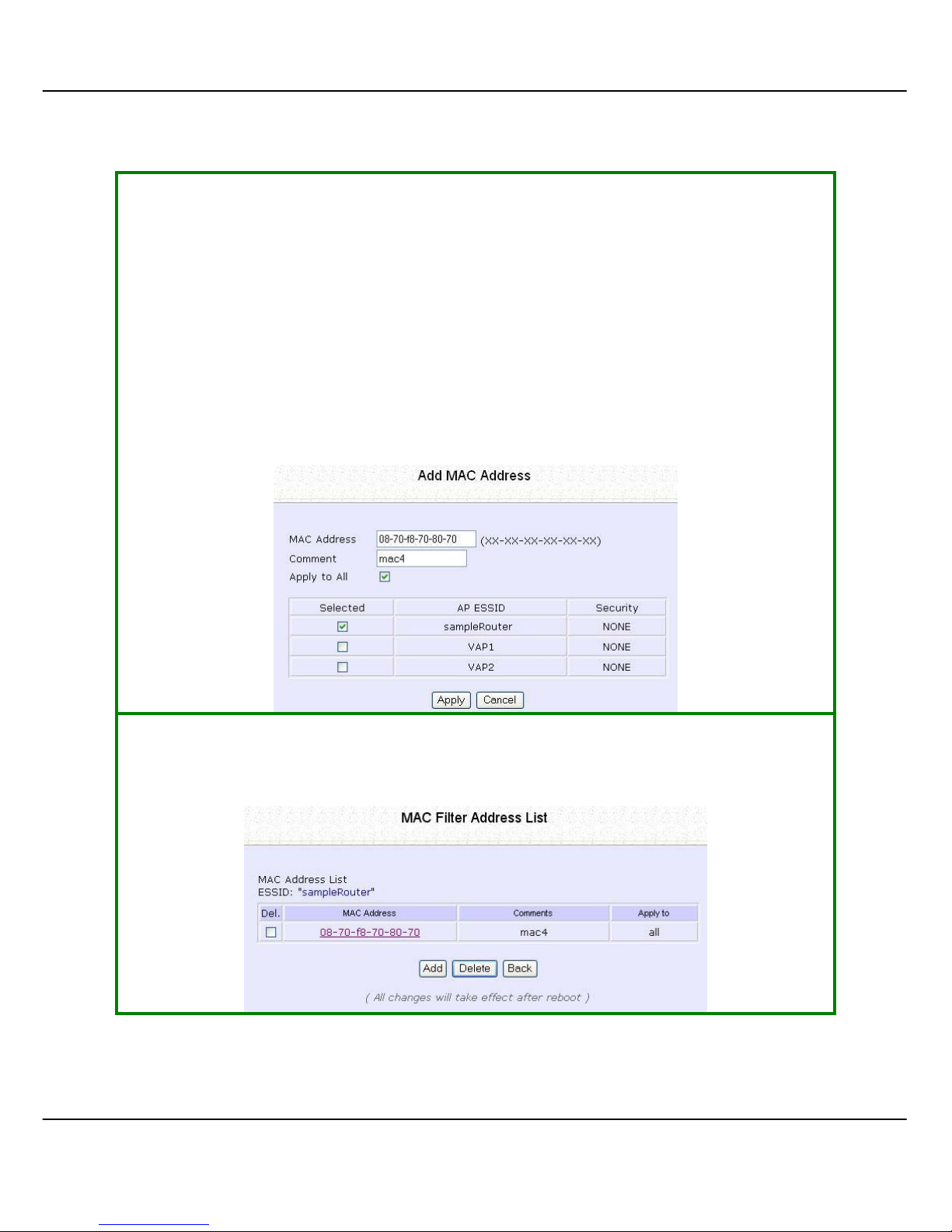
90
SStteepp 44::
Enter the MAC Address of the client in the format xx-xx-xx-xx-xx-xx, where x
can take any value in the range 0-9 or a-f.
Enter the Comment. This describes the MAC Address you have entered.
To apply to all virtual access points: Check AAppppllyy ttoo AAllll.
To apply to specific virtual access point: Select the checkb ox of the corresponding
AP.
Click the AAppppllyy button.
SStteepp 55::
MAC Filter Address List page displays with updated MAC Address List.
Page 98
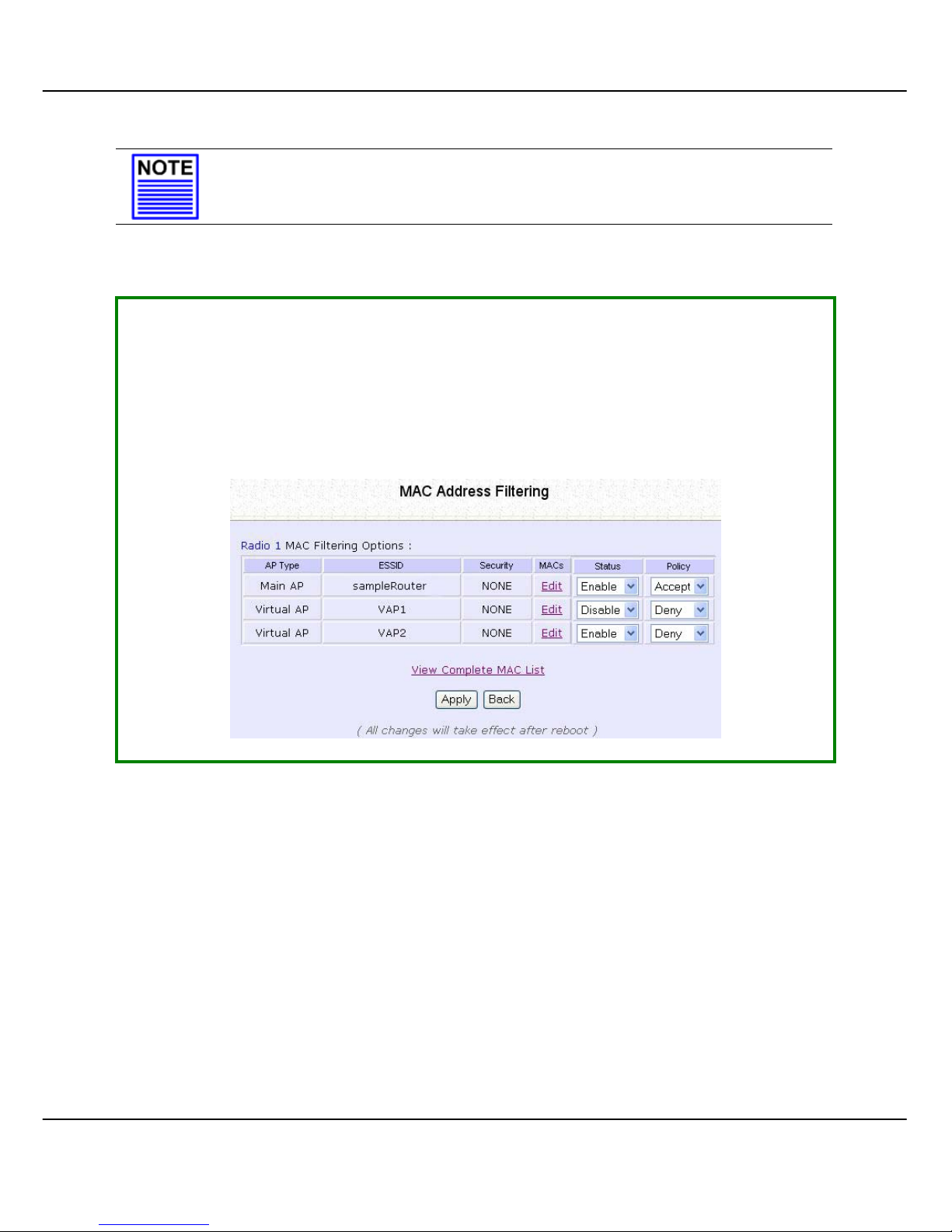
91
NOTE
Please reboot to effect all changes and new MAC address
entries.
D
D
EELLEETTEE AA
MMAACC
AADDDDRREESSSS FFRROOMM AALLLL AACCCCEESSSS PPOOIINNTTS
S
..
SStteepp 11::
Select MMAACC FFiilltteerriinngg from WWLLAANN SSeettuupp((aa//bb//gg)).
MAC Address Filtering page displays.
Click VViieeww CCoommpplleettee MMAACC
LLiisstt.
.
(This displays the MAC Address List of the radio card.)
Page 99
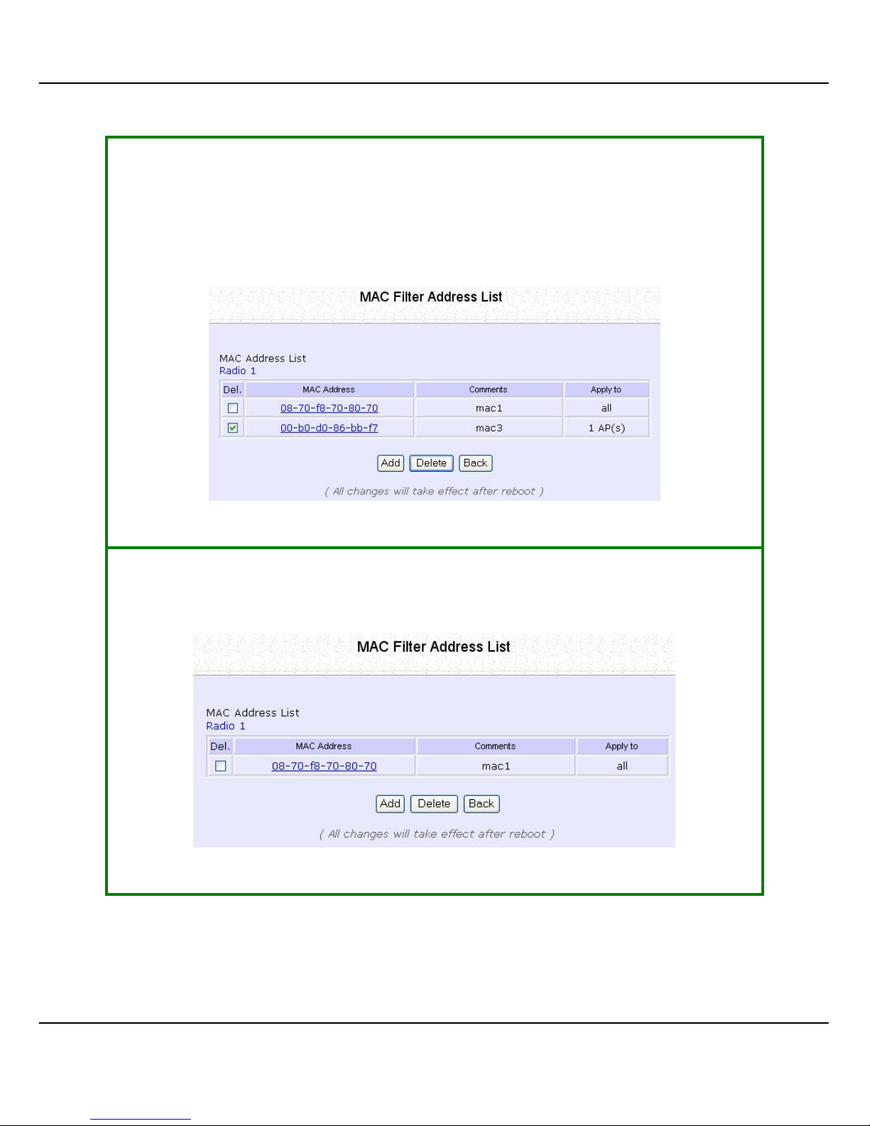
92
SStteepp 22::
MAC Filter Address List page displays.
Select the checkbox of the MAC address you wish to delete.
Click the DDeelleettee button.
SStteepp 33::
MAC Filter Address List page displays with updated MAC Address List.
Page 100
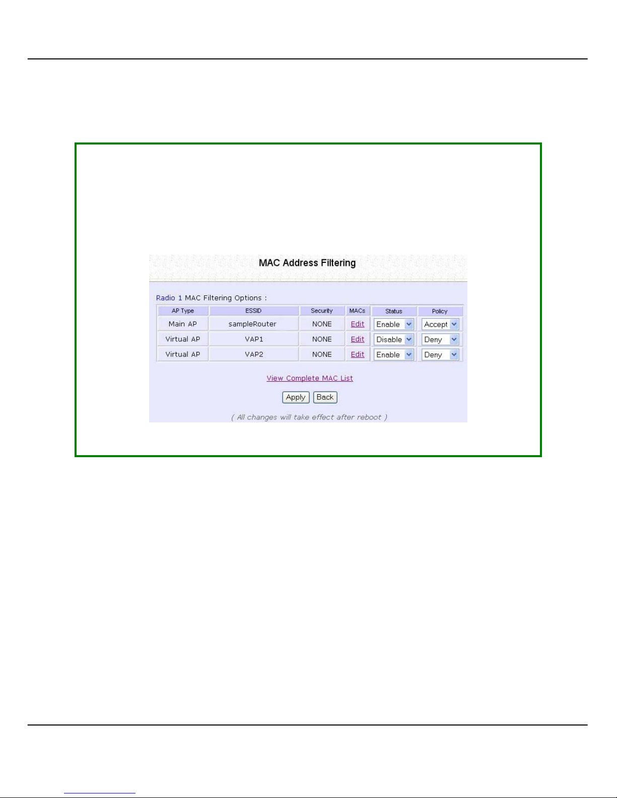
93
D
D
EELLEETTEE AA
MMAACC
AADDDDRREESSSS FFRROOMM IINNDDIIVVIIDDUUAALL AACCCCEESSSS PPOOIINNT
T
..
SStteepp 11::
Select MMAACC FFiilltteerriinngg from WWLLAANN SSeettuupp((aa//bb//gg)).
MAC Address Filtering page displays.
Click EEddiitt for the corresponding access point.
 Loading...