


© Copyright 2006 Compex Systems Pte Ltd
All Rights Reserved
This document contains information, which is protected by copyright.
Reproduction, adaptation or translation without prior permission is prohibited,
except as allowed under the copyright laws.
Trademark Information
Compex®, ReadyLINK® and MicroHub® are registered trademarks of Compex,
Inc. Microsoft Windows and the Windows logo are the trad emarks of Microsoft
Corp. NetWare is the registered trademark of Novell Inc. All other brand and
product names are trademarks or registered trademarks of their respective
owners.
Notice: Copyrights © 2006 by Compex, Inc. All rights reserved. Reproduction,
adaptation, or translati on without prior permi ssion of Compex, Inc. is prohibi ted,
except as allowed under the copyright laws.
Manual Revision by Daniel
Manual Number: U-0496-V1.3C Version 1.3 September 2006
Disclaimer
Compex, Inc. provides this manual without warranty of any ki nd, expressed or
implied, including but not limited to the implied warranties of merchantability
and fitness for a particular purpose. Compex, Inc. may make improvements
and/or changes to the product and/or specifications of the prod uct described
in this manual, without prior notice. Compex, Inc will not be liable for any
technical inaccuracies or typographi cal errors found in thi s guide. Changes ar e
periodically made to the information contained herein and will be
incorporated into later versions of the manual. The information contained is
subject to change without prior noti c e.
Your Feedback
We value your feedback. If you find any errors in this user’s manual, or if you
have suggestions on improving, we would like to hear from you. Please contact
us at:
Fax: (65) 62809947
Email:
feedback@compex.com.sg

iii
FCC NOTICE
This device has been tested and found to comply with the limits for a Class B
digital device, pursuant to Part 15 of the FCC Rules. These limits are desi gned to
provide reasonable protection against harmful interference in a residential
installation. This device generates, uses and can radiate radio frequency
energy and, if not installed and used in accordance with the instru ctions, may
cause harmful interference to radio communications. However, there is no
guarantee that interference will not occur in a particular installation. If this
device does cause harmful interference to radio or television reception, the
user is encouraged to try to correct the interference by one or more of the
following measures:
Reorient or relocate the receiv ing antenna.
Connect the computer i nto an outlet on a circuit different from that to which
the receiver is connected.
Increase the separation between the computer and receiver.
Consult the dealer or an experienced radio/TV technician for help.
Caution: Any changes or modifications not expressly approv ed by the grantee
of this device could void the user's authority to operate the equipment.
FCC Compliance Statement: This device complies with Part 15 of the FCC Rules.
Operation is subject to the foll o wing two conditions:
This device may not cause harmful interference, and
This device must accept any interference received, including interference that
may cause undesired operation.
This device must accept any interference received, including interference that
may cause undesired operation.
Products that contain a rad io transm itter are labelled with FCC I D and may al so
carry the FCC logo.
Caution: Exposure to Radio Frequency Radiation.
To comply with the FCC RF exposure compliance requirements, the following
antenna installation and device operating configurati ons m u st be satisfied:
a. For configurations using the integral antenna, the separation distance
between the antenna(s) and any person’s body (including hands, wrists,
feet and ankles) must be at least 2.5cm (1 inch).
b. For configurations using an approved external antenna, the separation
distance between the antenna and any person’s body (including hands,
wrists, feet and ankles) must be at least 20cm (8 inch).

iv
The transmitter shall not be coll ocated wi th other transm itters or antennas.
ICES 003 Statement
This Class B digital apparatus complies with Canadian ICES-003.
Declaration of Conformity
Compex, Inc. declares the following:
Product Name: Wireless Access Point with Integrated PoE
Model No.: WP54G conforms to the following Product Standards:
This device complies with the Electromagnetic Compatibility Directive
(89/336/EEC) issued by the Commission of the European Community.
Compliance with this directive implies conformity to the following European
Norms (in brackets are the equivalent international standards.)
Electromagnetic Interference (Conduction and Radiation)
: EN 55022 (CISPR 22)
Electromagnetic Immunity
: EN 55024 (IEC61000-4-2, 3,4,5,6,8,11)
Low Voltage Directive:
EN 60 950: 1992+A1: 1993+A2: 1993+A3: 1995+A4:
1996+A11: 1997.
Therefore, this product is in conformity with the following regional standards:
FCC Class B: following the provisions of FCC Part 15 directi ve, CE Mark: following
the provisions of the EC directive.
Compex, Inc. also declares that:
The wireless card in this product complies with the R&TTE Directi ve (1999/5/EC)
issued by the Commission of the European Community. Compliance with this
directive implies conformity to the foll owing:
EMC Standards:
FCC: 47 CFR Part 15, Subpart B, 47 CFR Part 15, Subpart C
(Section 15.247); CE: EN 300 328-2, EN 300 826 (EN 301 489-17)
Therefore, this product is in conformity with the following regional standards:
FCC Class B: following the provisions of FCC Part 15 directi ve, CE Mark: following
the provisions of the EC directive.
v
Technical Support Information
The warranty information and registration form are found in the Quick Install
Guide.
For technical support, you may contact Compex or its subsidiaries. For your
convenience, you may also seek techni cal assistance from the l ocal distributor ,
or from the authorized dealer/reseller that you have purchased this product
from. For technical support by email, write to
support@compex.com.sg.
Refer to the table below for the nearest Technical Support Centres:
Technical Support Centres
Contact the technical support centre that servi ces your location.
U.S.A., Canada, Latin America and South America
Write
Compex, Inc.
840 Columbia Street, Suite B
Brea, CA 92821, USA
Call
Fax
Tel:
Tel:
Fax:
+1 (714) 482-0333 (8 a.m.-5 p.m. Pacific time)
+1 (800) 279-8891 (Ext.122 Technical Support)
+1 (714) 482-0332
Asia, Australia, New Zealand, Middle East and the rest of the World
Write
Compex Systems Pte Ltd
135, Joo Seng Road #08-01, PM Industrial Building
Singapore 368363
Call
Tel:
Tel:
Fax:
(65) 6286-1805 (8 a.m.-5 p.m. local time)
(65) 6286-2086 (Ext.199 Technical Support)
(65) 6283-8337
Internet
access/
E-mail:
FTPsite:
support@compex.com.sg
ftp.compex.com.sg
Website: http://www.cpx.com or http://www.compex.com.sg
Fax

vi
About This Document
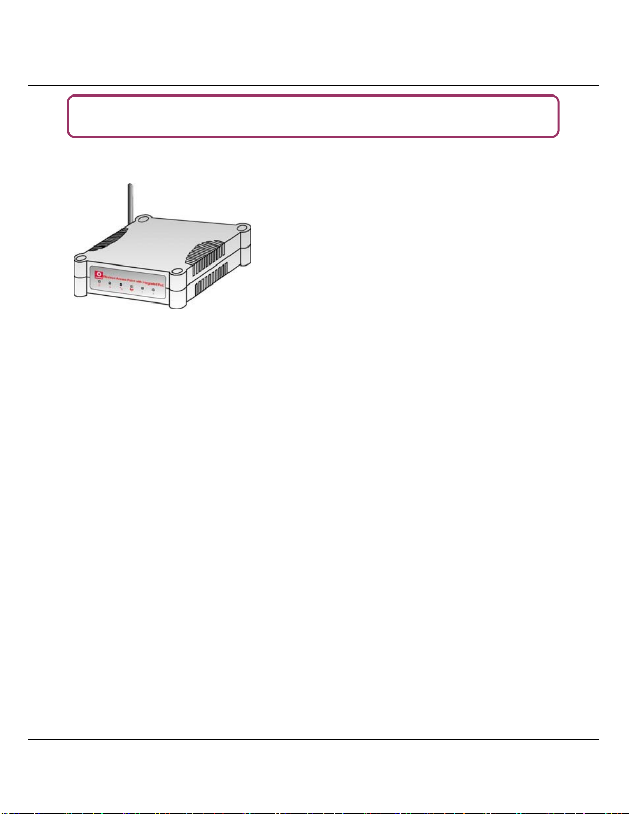
The product described in this document, Wireless Access Point with I ntegrated
PoE, WP54G is a licensed product of Compex Systems Pte Ltd. This document
contains instructions for installing, configuring and using WP54G. It also gives an
overview of the key applicati ons and the networking concepts with respect to
the product.
This documentation is for both Network Administrators and the end user who
possesses some basic knowledge in the networking structure and protocols.
It makes a few assumptions that th e host computer has already been installed
with TCP/IP and already up & running and accessing the Internet. Procedures
for Windows 98SE/ME/2000/XP operating systems are included in this document.
However, for other operating system, you may need to refer to your operati ng
system’s documentation for networking.
How to Use this Document
This document may become superseded, i n which case you may find its latest
version at:
http://www.compex.com.sg
The document is written in such a way th at you as a user will find it convenient
to find specific information pertai ning to the product. It comprises of chapters
that explain in detai ls on the installation and confi g uration of WP54G.
Firmware
This manual is written based on Firmware version 2.02
vii
Conventions
In this document, special conventions are used to help and present the
information clearly. The Wireless Access Point with Integrated PoE is often
referred to as WP54G or Access Point in this document. Below is a list of
conventions used throughout.
NOTE
This section will consist of important features or instructions
CAUTION
This section concerns risk of injury, system damage or loss of data
WARNING
This section concerns risk of severe injury
References on Menu Command, Push Button, Radio Button, LED and Label
appear in Bold. For example, “Click on Ok.”

viii
Copyrights © 2006 Compex Systems Pte Ltd ................................................................ i
Trademark Infor mation ..................................................................................................... i
Disclaimer............................................................................................................................ i
Your F eedback...................................................................................................................i
FCC NOTICE........................................................................................................................ii
Declaration of Conformity ...............................................................................................ii
Technical Supp ort Info rmation.......................................................................................iii
About This D ocument...................................................................................................... iv
How to Use th i s Do c u m e nt............................................................................................. iv
Firmware............................................................................................................................iv
Conventions...................................................................................................................... iv
CHAPTER 1: PRODUCT OVERVIEW..............................................1
Introduction...............................................................................................................1
Features and Benefits..............................................................................................2
When to use which mode ......................................................................................3
Access Point Mo de............................................................................................3
Access Point Client Mod e ................................................................................4
CHAPTER 2: HARDWARE INS TALLATION.....................................5
Setup Requirements ................................................................................................5
Hardware Installation ..............................................................................................5
OPTION On e: Using power adapter to supply p ower to the unit..............5
OPTION Two: Using PoE to supply po wer to the u nit....................................7
Optional: Mounting on the Wall....................................................................10
CHAPTER 3: ACCESS TO WEB-BASED INTERFACE ...................11
Access to the Web interface with uConfi g.......................................................11
Manual access to web-based interface via Internet Explorer......................15
CHAPTER 4: COMMON CONFIGURATION ..............................20
Manage ment Port Setup......................................................................................20
Setti ng up your LAN.........................................................................................21
To view the active DHCP leases....................................................................24
To reserve specific IP addresses for predetermined DHCP clients..........25
WLAN Setup ............................................................................................................28
To configur e the Basic setup of the wireless mode ...................................29

ix
To configure the Security setup of the wireless mode ...............................43
To configur e the Advanced s etup of the wireless mode.........................43
Statistics..............................................................................................................46
STP Setu p..................................................................................................................48
MAC Filtering...........................................................................................................53
Add a MAC address to the MAC Address List............................................54
Delete a MAC address from all access points. ..........................................57
Delete a MAC address from individual access point................................59
Edit MAC address from the MAC Address List............................................61
CHAPTER 5: WLAN SE CURITY.....................................................63
How to se t up WEP.................................................................................................64
How to se t up WPA-Personal ................................................................................66
How to set up 802.1x/RADIUS...............................................................................68
How to set up WPA Enter prise ..............................................................................70
CHAPTER 6: WI RE LE SS EXTENDED FEATURES ............................73
Virtual AP (Multiple SSID).......................................................................................73
Preferred APs (Only available in Client Mode).................................................75
Long Distance Parameters...................................................................................76
Point-to-Point & Point-to-MultiPoint Setup .........................................................79
CHAPTER 7: SYSTE M UTILITIES .....................................................82
Using th e SYSTEM TOOLS Men u............................................................................82
System Identity..................................................................................................82
System Clock Setup.........................................................................................84
Firmwa re Up grade...........................................................................................85
Backup or Reset S ettings ................................................................................87
Reboot System..................................................................................................90
Change Password............................................................................................91
Logout................................................................................................................92
Using th e HELP menu.............................................................................................93
Get Technical Sup p or t....................................................................................93
About System....................................................................................................94

x
APPENDIX I: FIRMWARE RECOVERY .........................................95
APPEND IX II: TCP/ IP CONFIGURATION.....................................97
For Wind ows 95/ 9 8/ 98 S E/M E /N T ....................................................................97
For Windows XP/2000.......................................................................................99
APPENDIX III: PANEL VIEWS & DESCRIPTIONS........................102
APPENDIX IV: VIRTUAL AP (MULTI-SSID) FAQ.........................105
APPENDIX V: TECHNICAL SPECIFICATIONS ...........................109
1
CChhaapptteerr 11:: PPrroodduucctt O
Ovveerrvviieeww
I
I
NNTTRROODDUUCCTTIIOON
N
The high-performance access point (AP) is designed
for enterprise and public access applications.
Embedded with the Atheros chipset, it boasts network
robustness, stability and wider network coverage.
Based on 802.11g, the access point supports highspeed data transmission of up to 54Mbps in the 2.4GHz
frequency band.
The access point is capable of operating in different
modes: Access Point and Access Point Client, which
makes it suitable for a wide variety of wireless applications, including long-distance
deployments.
Equipped with an SMA connector for external antenna support, the access point
provides a wider coverage for your network. Moreov er, its integra ted Power over E thernet
(PoE) allows the access point to be used in areas where power outlets are not readily
available.
To protect your security and privacy, the access point is armed with many enhanced
wireless security features such as Wi-Fi Protected Access (WPA), WPA2 (with Advanced
Encryption Standard encryption) MAC Address Filtering, IEEE 802.1x Authentication and
64/128-bit WEP (Wired Equivalent Privacy) to ensure privacy for the heterogeneous mix of
users within the same wireless network.
The access point also incorporates a unique set of advanced features such as: Virtual AP
to deliver multiple services; Long-Range parameter fine-tuning which provide the access
point wi th the ability to au to-calculate pa rameters such as slot time, ACK ti me-out and
CTS time-out to achieve a longer range; and Spanning Tree Protocol (STP) which provides
extra redundancy and the ability to auto-reconfigure when there are changes in the
network topology.

2
F
F
EEAATTUURREESS AANNDD
B
B
EENNEEFFIITTS
S
The access point has been designed for high performance and offers a rich
suite of features, with which you shoul d acquaint yourself to be able to exploit
your access point’s full potential.
Virtual AP (Multiple SSID)
Virtual AP implements mSSID (Multi-SSID)
This allows a single wireless card to be set up with multiple virtual AP
connections with different SSIDs or BSSID (Basic Service Set Identifier) and
security modes.
Highly Secured Wireless Network
The access point supports the highest available wireless security standard:
Wi-Fi Protected Access 2. WPA2 has two different modes: WPA2-PSK for
SOHO users and WPA2-EAP for Enterprise users. The access point also
supports IEEE 802.1x for secure and centralized user-based authentication.
Wireless clients are thus required to authenticate through highly secure
methods like EAP-TLS, EAP-TTLS, and EAP-PEAP, in order to obtain access to
the network.
Smart Select
This feature will automati cally scan and recommend the best channel that
the access point can utili ze.
uConfig Utility
Compex’s exclusive uConfig utility allows users to access the user-friendly
Web configuration interfac e of the access point without having to chang e
the TCP/IP setup of the workstation.
STP
Spanning-Tree Protocol provides path redundancy while preventing
undesirable loops in the network. It forces certain redundant data paths into
a standby (blocked) state. If one network segment in the Spanning-Tree
Protocol becomes unreachable, or if Spanning-Tree Protocol costs chang e,
the spanning-tree algorithm reconfigures the spanning-tree topology and
re-establishes the link by activating the standby path.
Point-to-Point & Point-to-MultiPoint Support
Point-to-Point and Point-to-MultiPoint communication between different
buildings enables you to bridge wireless clients that are kilometres apart
while unifying the networks.
3
W
W
HHEENN TTOO UUSSEE WWHHIICCHH MMOODDE
E
The access point is v ersatile in the sense that i t may operate in 2 di fferent types
of modes: Access Point Mode and Client Mode.
This section presents a brief outline of the different network applications that
can be accommodated through the different modes of the access point.
A
A
CCCCEESSSS
P
P
OOIINNTT
M
M
OODDE
E
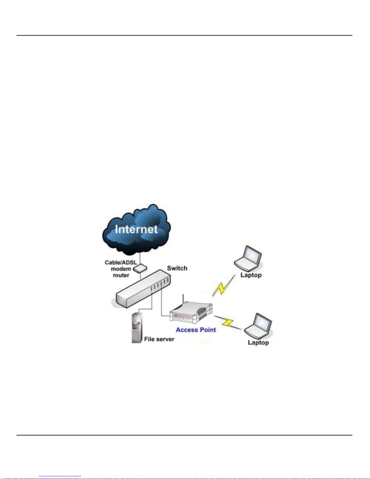
This is the default mode of the access point. The Access Point mode enables
you to bridge wireless clients to access the wired network infrastru cture and to
communicate with each other.
In the example above, the wireless users will be able to access the file server
connected to the switch through the access point in Access Poi nt m ode.
4
A
A
CCCCEESSSS
P
P
OOIINNTT
C
C
LLIIEENNTT
M
M
OODDE
E
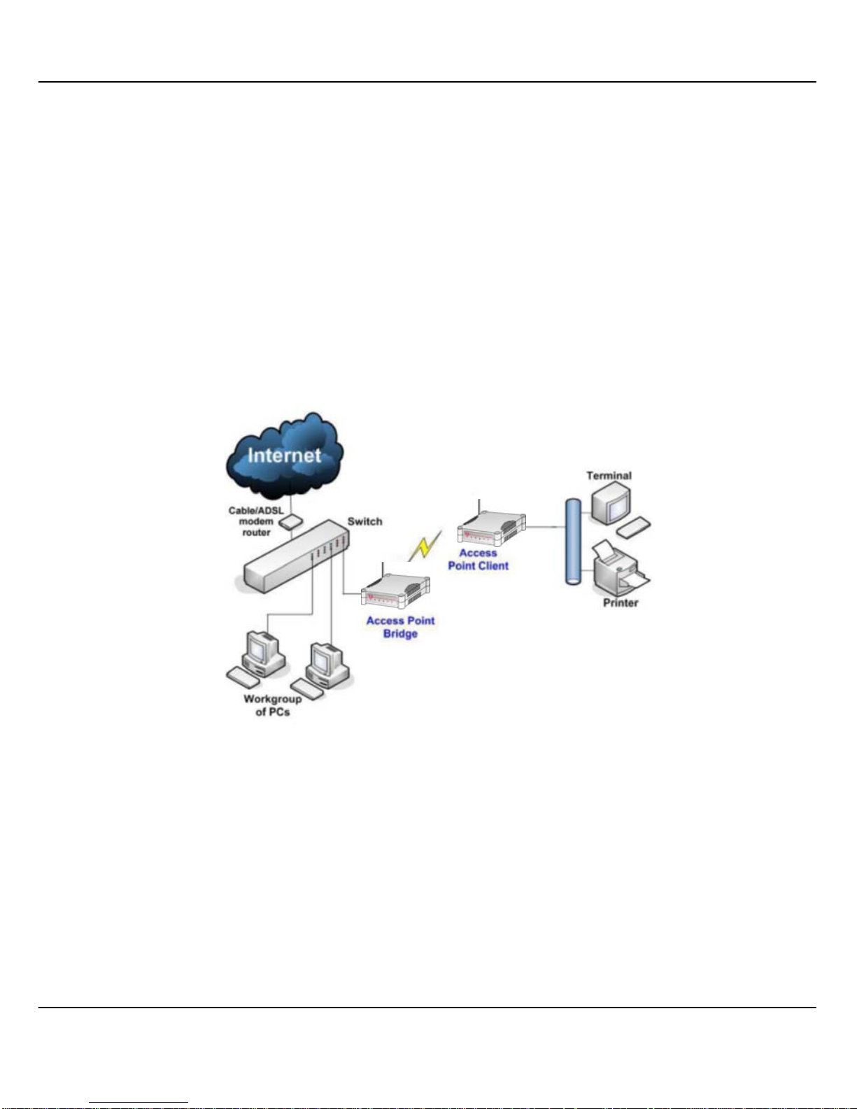
In Access Point Client mode, the device acts as a wireless client.
When connected to an access point, it will create a network link between the
Ethernet network connected at this cli ent device, and the wireless and Ethern et
network connected at the access point.
In this mode it can only connect with an access point. Other wireless clients
cannot connect with it directly unless connected to the same access point allowing them to communicate with al l devices connec ted at th e Ethern et port
of the WP54G.
In the example above, the workgroup PCs will be able to access the printer
connected to the access point in Access Point Client mode.
5
CChhaapptteerr 22:: HHaarrddwwaarree IInnssttaallllaattiioonn
S
S
EETTUUPP
R
R
EEQQUUIIRREEMMEENNTTS
S
Before starting, please verify that the fol lowing is available:
CAT5/5e networking cable
At least one computer is installed with a Web browser and a wired or wireless
network interface adapter
TCP/IP protocol is installed and IP address parameters are properly configured
on all your network’s nodes
H
H
AARRDDWWAARREE
I
I
NNSSTTAALLLLAATTIIOON
N
The access point can be p owered using either the power adap ter provided or
a PoE Injector. The installation process for both options is described below.
OOPPTTIIOONN O
O
NNE
E
:: U
U
SSIINNGG PPOOWWEERR AADDAAPPTTEERR TTOO SSUUPPPPLLYY PPOOWWEERR TTOO TTHHEE UUNNIITT
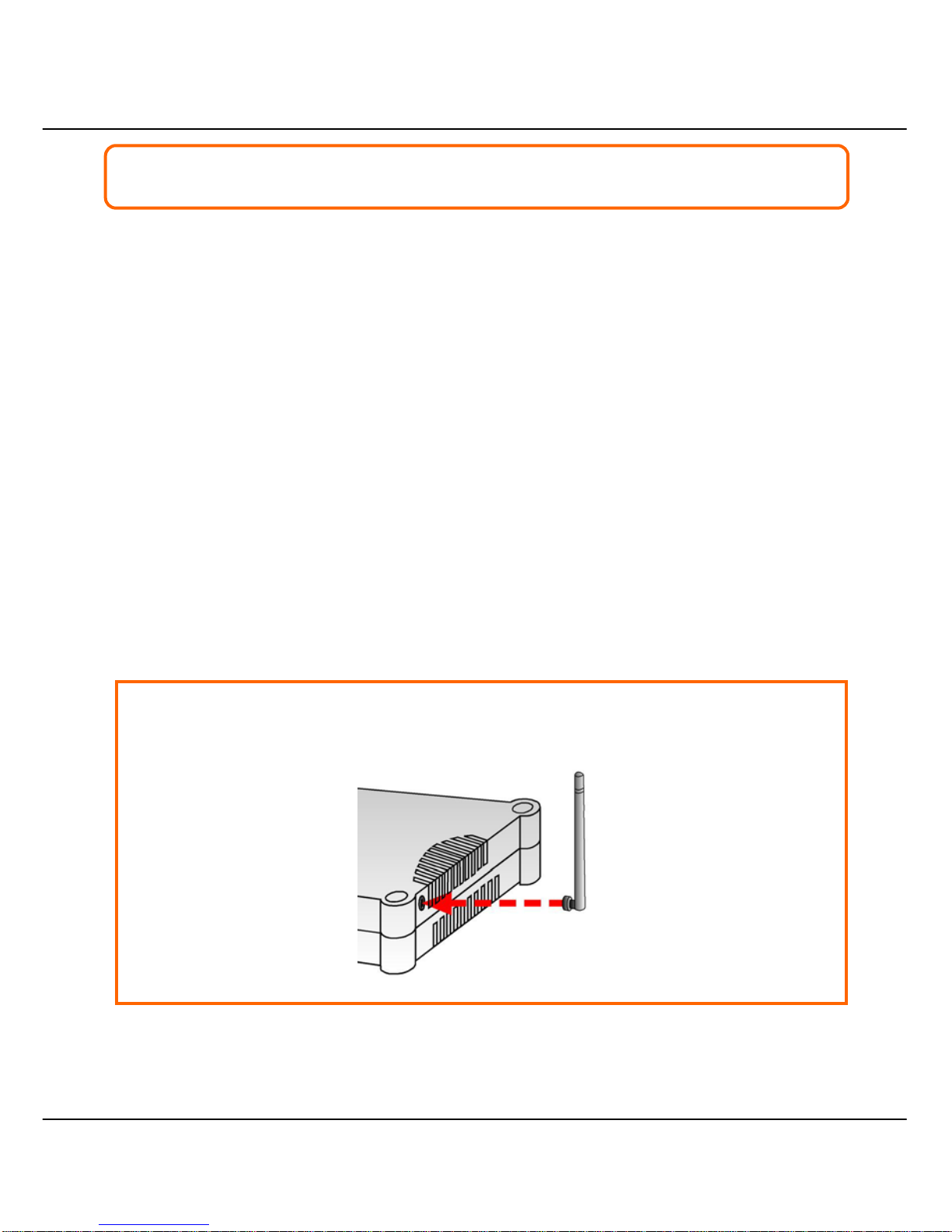
SStteepp 11::
Connect the external antenna to the SMA connector of the access poi nt.

6
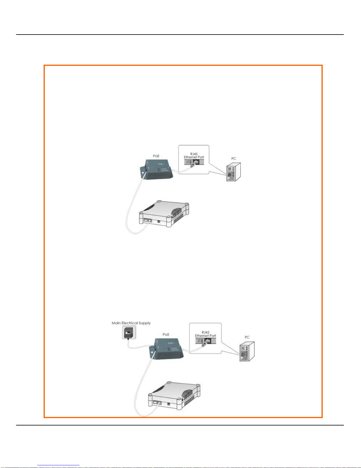
SStteepp 22::
Insert one end of the Ethernet cable to any of the Ethernet ports on your
access point, and the other end of the cable to your PC’s Ethernet network
adapter.
SStteepp 33::
Attach the power adapter to the main electrical supply, and connect the
power plug into the socket of the access point.
SStteepp 44::
Turn ON the power supply and power ON your PC. Notice that the LEDs: Power
and Port 1 or 2 (depending on which port you have connected the RJ45
Ethernet cable to) have lighted up. This indicates that connection has been
established successfully between your access point and your PC.
PC

7
OOPPTTIIOONN T
T
WWO
O
:: U
U
SSIINNGG
P
P
O
O
EE
TTOO SSUUPPPPLLYY PPOOWWEERR TTOO TTHHEE UUNNIIT
T
The access point is fully compati ble with a Power-Ov er-Ethernet (PoE) kit. A PoE
accessory supplies operational power to th e wireless AP via the Ethernet cable
connection.
Users who have already purchased a PoE and who wish to use it to supply
power to the access point may follow the installation procedures shown below:
SStteepp 11::
Connect the external antenna to the SMA connector of the access poi nt.
SStteepp 22::
Use an RJ45 Ethernet cable to connec t one end of the cable to the LAN OUT
port of the Injector and the other end to Ethernet port 1 of the access point.
8
SStteepp 33::
Next, connect the RJ45 Ethernet cable attached to the PoE Injector to your
PC’s Ethernet network adapter.
Once you have finished config uring your access point, you can connect the
PoE Injector’s RJ45 Ethernet cable to your network device, such as to a switch
or hub.
SStteepp 44::
Connect the power adapter supplied in the PoE kit to the main electrical
supply and the power plug into the socket of the injector.
Note:
The voltage and current supplied to the po wer adapter and the PoE kit power
adapter are different. Do not interchange the power adapters.

9
SStteepp 55::
Turn on your power supply. Notice that the Power LED has lighted up. This
indicates that the access point is receiving power through the Compex PoE
Injector. Notice also that the corresponding port LEDs have lighted up. This
indicates that connection between your access point and your PC has been
established.

10
O
O
PPTTIIOONNAAL
L
:: M
M
OOUUNNTTIINNGG OONN TTHHEE
W
W
AALLL
L
SStteepp 11::
Screw the mount onto the unit.
SStteepp 22::
Align the unit and mount to the wall.
Use the mount as a guide, make 2 marks and drill 2 holes into the wall.
SStteepp 33::
Next, secure the unit and mount to the wall.

11
CChhaapptteerr 33:: AAcccceessss ttoo W
Weebb--bbaasseedd
IInntteerrffaaccee
There are two methods to access to the web-based Interface of the access
point:
Through our Compex Utility – uConfig
You can access to the web-based interface directly without the need to
assign a different IP address to your PC.
By entering the IP address of the access point in the address bar of Internet
Explorer
You need to assign an IP address to your PC, such as 192.168.168.x, where x
can take any value from 2 to 254, so that it is in the same subnet as the
access point.
A
A
CCCCEESSSS TTOO TTHHEE
W
W
EEBB IINNTTEERRFFAACCEE WWIITTHH U
U
C
C
OONNFFIIG
G
Compex has developed a powerful uConfig utility that has been desi gned to
give you direct access to the Web interface.
SStteepp 11::
Insert the Product CD into your CD-ROM drive. The CD will run automatically.
SStteepp 22::
From the Utilities section, select to install the uConfig utility to your hard disk.

12
SStteepp 33::
When the utility has been installed, double-click on the uConfig icon. The
following screen will appear, click on the Yes button to proc eed .
SStteepp 44::
Select WWPP5544GG in the CCoommppeexx PPrroodduuccttss LLiisstt section and click on the OO
ppeenn WWeeb
b
button. To retrieve and display the latest device(s) in the list, click on the
R
R
eeffrreessh
h button.

13
SStteepp 55::
Do not exit the uConfig program whil e accessing to the web-based interface.
This will disconnect you from the device. Click on the OK button to proceed.
SStteepp 66::
At the login page, press the LLOOGGIINN!! button to enter the configuration page.
The default password is “password”.

14
SStteepp 77::
You will then reach the home page of the access point’s web-based
interface.

15
M
M
AANNUUAALL AACCCCEESSSS TTOO WWEEB
B
-
-
BBAASSEEDD IINNTTEERRFFAACCEE VVIIAA
I
I
NNTTEERRNNEETT
E
E
XXPPLLOORREER
R
For this method, you need to assign an IP address to your PC so that it belongs
to the same subnet as your access point. In this example, we are using Windows
XP for illustration. For Windows 98/98SE/2000/NT/ME, kindly refer to Appendix II
“TCP/IP Configuration”.
SStteepp 11::
Go to your desktop, right-click on My Network Places icon and select
Properties.
SStteepp 22::
Go to your network adapter icon, right-click and select Properties.
16
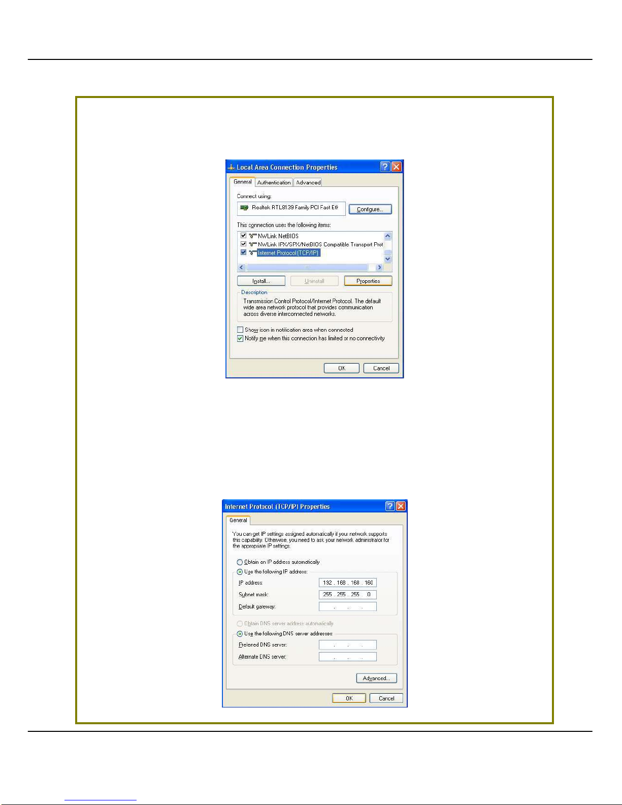
SStteepp 33::
Highlight Internet Protocol (TCP/IP) and click on the PPrrooppeerrttiieess button.
SStteepp 44::
Select the radio button for Use the following IP address. Enter the IP Address
and Subnet Mask as 192.168.168.x and 255.255.255.0, where x can be any
number from 2 to 254, except 1. In this example, we are using 192.168.168.160
as the static IP Address.

17
SStteepp 55::
Click on the OOKK button to close all windows.
SStteepp 66::
Next, in order to check if the IP address has been correctly assigned to your
PC, go to Start menu, Accessories, select Command Prompt and type the
command ipconfig/all.
Your PC is now ready to configure the access point.
SStteepp 77::
Launch your Web browser. Under the Tools tab, select Internet Options.
18
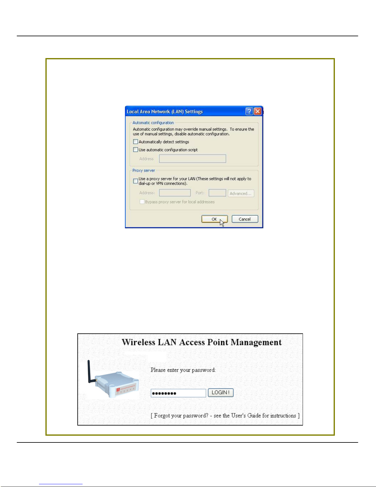
SStteepp 88::
Open the Connections tab and in the LAN Settings section, disable all the
option boxes. Click on the OOKK button to update the changes.
SStteepp 99::
At the Address bar, enter http://192.168.168.1 and press Enter on your
keyboard.
SStteepp 1100::
At the login page, click on the LLOOGGIINN!! button to enter the configuration
pages.

19
You will then reach the home page of the access point’s Web interface.

20
CChhaapptteerr 44:: CCoom
m
m
moonn CCoonnffiigguurraattiioonn
This chapter illustrates the following features, which are available in ALL
the
operating modes of the access point, unless stated otherwise.
• Management Port
• WLAN Basic Setup
• WLAN Security
• STP Setup
• SNMP
• MAC Filtering
• Antenna Alignment
M
M
AANNAAGGEEMMEENNTT
P
P
OORRTT
S
S
EETTUUP
P
This section shows you how to customize the parameters of the ac cess point to
suit the needs of your network. It also explai ns how to make use of the built-in
DHCP server of the access point.
 Loading...