

Page 1

Page 2

ii
© Copyright 2007 Compex Systems Pte Ltd
All Rights Reserved
This document contains information, which is protected by copyright.
Reproduction, adaptation or translation without prior permission is prohibited,
except as allowed under the copyright laws.
Trademark Information
Compex® is a registered trademark of Compex, Inc. Microsoft Windows and the
Windows logo are the trademarks of Microsoft Corp. NetWare is the registered
trademark of Novell Inc. All other brand and product names are trademarks or
registered trademarks of their respective owners.
Notice: Copyrights © 2007 by Compex, Inc. All rights reserved. Reproduction,
adaptation, or translation without prior permission of Compex, Inc. is prohibited,
except as allowed under the copyright laws.
Manual Revision by Daniel
Manual Number: U-0524-V1.3 Version 1.3January 2007
Disclaimer
Compex, Inc. provides this manual without warranty of any kind, expressed or
implied, including but not limited to the implied warranties of merchantability
and fitness for a particular purpose. Compex, Inc. may make improvements
and/or changes to the product and/or specifications of the product described
in this manual, without prior notice. Compex, Inc will not be liable for any
technical inaccuracies or typographical errors found in this guide. Changes are
periodically made to the information contained herein and will be
incorporated into later versions of the manual. The information contained is
subject to change without prior notice.
Your Feedback
We value your feedback. If you find any errors in this user’s manual, or if you
have suggestions on improving, we would like to hear from you. Please contact
us at:
Fax: (65) 62809947
Email:
feedback@compex.com.sg
Page 3

FCC NOTICE
This device has been tested and found to comply with the limits for a Class B
digital device, pursuant to Part 15 of the FCC Rules. These limits are designed to
provide reasonable protection against harmful interference in a residential
installation. This device generates, uses and can radiate radio frequency
energy and, if not installed and used in accordance with the instructions, may
cause harmful interference to radio communications. However, there is no
guarantee that interference will not occur in a particular installation. If this
device does cause harmful interference to radio or television reception, the
user is encouraged to try to correct the interference by one or more of the
following measures:
! Reorient or relocate the receiving antenna.
! Connect the computer into an outlet on a circuit different from that to
which the receiver is connected.
! Increase the separation between the computer and receiver.
! Consult the dealer or an experienced radio/TV technician for help.
Caution: Any changes or modifications not expressly approved by the grantee
of this device could void the user's authority to operate the equipment.
FCC Compliance Statement: This device complies with Part 15 of the FCC Rules.
Operation is subject to the following two conditions:
This device may not cause harmful interference, and
This device must accept any interference received, including interference that
may cause undesired operation.
Products that contain a radio transmitter are labelled with FCC ID and may also
carry the FCC logo.
Caution: Exposure to Radio Frequency Radiation.
To comply with the FCC RF exposure compliance requirements, the following
antenna installation and device operating configurations must be satisfied:
a. For configurations using the integral antenna, the separation distance
between the antenna(s) and any person’s body (including hands, wrists,
feet and ankles) must be at least 2.5cm (1 inch).
b. For configurations using an approved external antenna, the separation
distance between the antenna and any person’s body (including hands,
wrists, feet and ankles) must be at least 20cm (8 inch).
The transmitter shall not be collocated with other transmitters or antennas.
iii
Page 4

ICES 003 Statement
This Class B digital apparatus complies with Canadian ICES-003.
Declaration of Conformity
Compex, Inc. declares the following:
Product Name: Wireless Access Point with PoE
Model No.: WP54AG conforms to the following Product Standards:
This device complies with the Electromagnetic Compatibility Directive
(89/336/EEC) issued by the Commission of the European Community.
Compliance with this directive implies conformity to the following European
Norms (in brackets are the equivalent international standards.)
Electromagnetic Interference (Conduction and Radiation)
Electromagnetic Immunity
Low Voltage Directive:
1996+A11: 1997.
Therefore, this product is in conformity with the following regional standards:
FCC Class B: following the provisions of FCC Part 15 directive, CE Mark: following
the provisions of the EC directive.
Compex, Inc. also declares that:
The wireless card in this product complies with the R&TTE Directive (1999/5/EC)
issued by the Commission of the European Community. Compliance with this
directive implies conformity to the following:
EMC Standards:
(Section 15.247); CE: EN 300 328-2, EN 300 826 (EN 301 489-17)
Therefore, this product is in conformity with the following regional standards:
FCC Class B: following the provisions of FCC Part 15 directive, CE Mark: following
the provisions of the EC directive.
FCC: 47 CFR Part 15, Subpart B, 47 CFR Part 15, Subpart C
: EN 55024 (IEC61000-4-2, 3,4,5,6,8,11)
EN 60 950: 1992+A1: 1993+A2: 1993+A3: 1995+A4:
: EN 55022 (CISPR 22)
iv
Page 5

Technical Support Information
Contact the technical support centre that services your location.
U.S.A., Canada, Latin America and South America
Write
Compex, Inc.
840 Columbia Street, Suite B
Brea, CA 92821, USA
! Call
Fax
Tel:
Tel:
Fax:
+1 (714) 482-0333 (8 a.m.-5 p.m. Pacific time)
+1 (800) 279-8891 (Ext.122 Technical Support)
+1 (714) 482-0332
Asia, Australia, New Zealand, Middle East and the rest of the World
Write
Compex Systems Pte Ltd
135, Joo Seng Road #08-01, PM Industrial Building
Singapore 368363
! Call
Tel:
Tel:
Fax:
(65) 6286-1805 (8 a.m.-5 p.m. local time)
(65) 6286-2086 (Ext.199 Technical Support)
(65) 6283-8337
Internet
access/
E-mail:
FTPsite:
support@compex.com.sg
ftp.compex.com.sg
Website: http://www.cpx.com or http://www.compex.com.sg
Fax
The warranty information and registration form are found in the Quick Install
Guide.
For technical support, you may contact Compex or its subsidiaries. For your
convenience, you may also seek technical assistance from the local distributor,
or from the authorized dealer/reseller that you have purchased this product
from. For technical support by email, write to
Refer to the table below for the nearest Technical Support Centres:
support@compex.com.sg.
Technical Support Centres
v
Page 6

About This Document
The product described in this document, Wireless Access Point with PoE,
WP54AG is a licensed product of Compex Systems Pte Ltd. This document
contains instructions for installing, configuring and using Access point. It also
gives an overview of the key applications and the networking concepts with
respect to the product.
This documentation is for both Network Administrators and the end user who
possesses some basic knowledge in the networking structure and protocols.
It makes a few assumptions that the host computer has already been installed
with TCP/IP and already up & running and accessing the Internet. Procedures
for Windows 98SE/ME/2000/XP operating systems are included in this document.
However, for other operating system, you may need to refer to your operating
system’s documentation for networking.
How to Use this Document
This document may become superseded, in which case you may find its latest
version at:
The document is written in such a way that you as a user will find it convenient
to find specific information pertaining to the product. It comprises of chapters
that explain in details on the installation and configuration of WP54AG.
http://www.compex.com.sg
Firmware
This manual is written based on Firmware version 1.5
vi
Page 7

Conventions
NOTE
This section will consist of important features or instructions
CAUTION
This section concerns risk of injury, system damage or loss of data
WARNING
This section concerns risk of severe injury
References on Menu Command, Push Button, Radio Button, LED and Label
appear in Bold. For example, “Click on Ok.”
In this document, special conventions are used to help and present the
information clearly. The Wireless Access Point with PoE is often referred to as
WP54AG or access point or AP in this document. Below is a list of conventions
used throughout.
vii
Page 8

Copyrights © 2007 Compex Systems Pte Ltd ................................................................ i
Trademark Information ..................................................................................................... i
Disclaimer............................................................................................................................ i
Your Feedback................................................................................................................... i
FCC NOTICE ........................................................................................................................ii
Declaration of Conformity ...............................................................................................ii
Technical Support Information .......................................................................................iii
About This Document...................................................................................................... iv
How to Use this Document............................................................................................. iv
Firmware ............................................................................................................................ iv
Conventions...................................................................................................................... iv
CHAPTER 1: PRODUCT OVERVIEW..............................................1
Introduction...............................................................................................................1
Features and Benefits..............................................................................................2
When to use which mode ......................................................................................4
Access Point Mode............................................................................................4
Access Point Client Mode ................................................................................5
Point to Point Mode ...........................................................................................6
Point to Multiple point Mode ...........................................................................7
Wireless Routing Client Mode ..........................................................................8
Gateway Mode.................................................................................................. 9
Wireless Adapter Mode ..................................................................................11
CHAPTER 2: HARDWARE INSTALLATION...................................12
Setup Requirements ..............................................................................................12
Hardware Installation ............................................................................................12
OPTION One: Using power adapter to supply power to the unit............12
OPTION Two: Using PoE to supply power to the unit..................................14
Optional: Mounting on the Wall....................................................................17
CHAPTER 3: ACCESS TO WEB-BASED INTERFACE ...................18
Access to the Web interface with uConfig.......................................................18
Manual access to web-based interface via Internet Explorer......................22
CHAPTER 4: COMMON CONFIGURATION ..............................27
Management Port Setup......................................................................................27
viii
Page 9

Setting up your LAN .........................................................................................28
To view the active DHCP leases....................................................................31
To reserve specific IP addresses for predetermined DHCP clients..........32
WLAN Setup ............................................................................................................35
To configure the Basic setup of the wireless mode ................................... 36
To configure the Security setup of the wireless mode...............................52
To configure the Advanced setup of the wireless mode .........................52
Statistics..............................................................................................................54
WAN Setup ..............................................................................................................61
Telnet/SSH Setup.....................................................................................................69
TELNET Command Line Interface ..................................................................72
Secure Shell Host Command Line Interface ...............................................73
WEB Mode...............................................................................................................75
SNMP Setup.............................................................................................................76
STP Setup..................................................................................................................77
MAC Filtering...........................................................................................................83
Add a MAC address to the MAC Address List............................................83
Delete a MAC address from all access points. .......................................... 87
Delete a MAC address from individual access point................................89
Edit MAC address from the MAC Address List. ...........................................91
CHAPTER 5: WLAN SECURITY .....................................................93
How to set up WEP.................................................................................................94
How to set up WPA-Personal................................................................................96
How to set up 802.1x/RADIUS...............................................................................98
How to set up WPA Enterprise............................................................................100
CHAPTER 6: WIRELESS EXTENDED FEATURES ..........................103
Access Control – The Wireless Pseudo VLAN...................................................103
Wireless Pseudo VLAN Per Node .................................................................104
Wireless Pseudo VLAN Per Group................................................................107
Wireless Setup - The Wireless Distributed System.......................................111
Long Distance Parameters...........................................................................117
CHAPTER 7: ADVANCED CONFIGURATION ..........................120
Routing...................................................................................................................120
To configure Static Routing ..........................................................................122
NAT..........................................................................................................................123
To configure Virtual Servers based on De-Militarized Zone Host ...........124
To configure Virtual Servers based on Port Forwarding ..........................126
ix
Page 10

To configure Virtual Servers based on IP Forwarding ..............................129
Bandwidth Control...............................................................................................130
To enable or disable Bandwidth Control...................................................130
To configure WAN Bandwidth Control Setting .........................................131
To configure LAN Bandwidth Control Setting ...........................................132
Remote Management........................................................................................134
To set up Remote Management.................................................................134
Parallel Broadband..............................................................................................135
To enable Parallel Broadband.....................................................................136
Email Notification .................................................................................................137
Static Address Translation...................................................................................139
DNS Redirection ...................................................................................................141
To enable/disable DNS Redirection............................................................143
Dynamic DNS Setup ............................................................................................143
To enable/disable Dynamic DNS Setup.....................................................144
To manage Dynamic DNS List......................................................................144
CHAPTER 8: SECURITY CONFIGURATION ...............................150
Packet Filtering .....................................................................................................150
To configure Packet Filtering........................................................................150
URL Filtering ...........................................................................................................154
To configure URL Filtering..............................................................................154
Firewall Configuration .........................................................................................155
To configure SPI Firewall................................................................................155
Firewall Logs ..........................................................................................................159
To view Firewall Logs......................................................................................159
CHAPTER 9: SYSTEM UTILITIES ...................................................160
Using the SYSTEM TOOLS Menu..........................................................................160
Ping Utility.........................................................................................................160
Syslog................................................................................................................161
System Identity................................................................................................164
System Clock Setup .......................................................................................165
Firmware Upgrade .........................................................................................166
Backup or Reset Settings ..............................................................................168
Reboot System................................................................................................171
Change Password..........................................................................................172
Logout ..............................................................................................................173
Using the HELP menu ...........................................................................................174
Get Technical Support ..................................................................................174
About System..................................................................................................175
x
Page 11

APPENDIX I: FIRMWARE RECOVERY .......................................176
APPENDIX II: TCP/IP CONFIGURATION...................................178
For Windows 95/98/98SE/ME/NT ..................................................................178
For Windows XP/2000.....................................................................................181
APPENDIX III: PANEL VIEWS & DESCRIPTIONS........................184
APPENDIX IV: COMMAND LINE INTERFACE COMMANDS...187
APPENDIX V: TECHNICAL SPECIFICATIONS ...........................192
xi
Page 12

CChhaapptteerr11::PPrroodduuccttOOvveerrvviieew
w
I
NNTTRROODDUUCCTTIIOON
I
The Wireless Access Point is a high-performance access point (AP) that is
designed for enterprise and public access applications. Embedded with the
Atheros chipset, it boasts network robustness, stability and wider network
coverage. Based on 802.11g and 802.11a, the access point supports highspeed data transmission of up to 54Mbps in the 2.4GHz and 5GHz frequency
band.
The access point is capable of operating in 7 modes: Access Point, Access
Point Client, Point-to-Point, Point-to-Multi Point, Wireless Routing Client, Gateway
and Wireless Adapter. Which makes it suitable for a wide variety of wireless
applications, including long-distance deployments.
Equipped with an SMA connector for external antenna support, the access
point provides a wider coverage for your network. Moreover, its integrated
Power over Ethernet (PoE) allows the access point to be used in areas where
power outlets are not readily available.
To protect your security and privacy, the access point is armed with many
enhanced wireless security features such as Wi-Fi Protected Access (WPA),
WPA2 (with Advanced Encryption Standard encryption) MAC Address Filtering,
IEEE 802.1x Authentication and 64/128-bit WEP (Wired Equivalent Privacy) to
ensure privacy for the heterogeneous mix of users within the same wireless
network.
The access point also incorporates a unique set of advanced features such as:
Wireless Distribution System (WDS) to wirelessly link associated access points
together and extend network coverage, Long-Range parameter fine-tuning
which provide the access point with the ability to auto-calculate parameters
such as slot time, ACK time-out and CTS time-out to achieve a longer range;
Spanning Tree Protocol (STP) which provides extra redundancy and the ability
to auto-reconfigure when there are changes in the network topology; Pseudo
VLAN which enables the creation of wireless isolated nodes or workgroups of
wireless clients to enhance security in a public access wireless network; HTTPS
which feature additional authentication and encryption; and Telnet which
allows remote connection; and SSH which provides a secure host connection.
N
1
Page 13

F
EEAATTUURREESSAANND
F
The access point has been designed for high performance and offers a rich
suite of features, with which you should acquaint yourself to be able to exploit
your access point’s full potential.
D
B
EENNEEFFIITTS
B
S
!!WWiirreelleessssDDiissttrriibbuuttiioonnSSyysstteemm((WWDDSS)
This feature allows linking of several access points, virtually creating a larger
network infrastructure that allows mobile users to roam wirelessly, while still
being able to access network resources.
P
!!WWiirreelleessssP
The unique Wireless Pseudo VLAN technology is a feature that allows wireless
clients to be segmented individually or into workgroups, thus blocking
access to another user’s/group’s PCs, and enhancing the privacy of the
wireless clients. This is especially useful in public hotspot deployment.
!!HHiigghhllyySSeeccuurreeddWWiirreelleessssNNeettwwoorrk
The access point supports the highest available wireless security standard:
Wi-Fi Protected Access 2. WPA2 has two different modes: WPA2-Personal for
SOHO users and WPA2-Enterprise for Enterprise users. The access point also
supports IEEE 802.1x for secure and centralized user-based authentication.
Wireless clients are thus required to authenticate through highly secure
methods like EAP-TLS, EAP-TTLS, and EAP-PEAP, in order to obtain access to
the network.
!SSmmaarrttSSeelleecctt
!
This feature will automatically scan and recommend the best channel that
the access point can utilize.
!!uuCCoonnffiiggUUttiilliitty
The exclusive uConfig utility allows users to access the user-friendly Web
configuration interface of the access point without having to change the
TCP/IP setup of the workstation.
sseeuuddooVVLLAAN
y
N
)
k
P
!!SSTTP
Spanning-Tree Protocol provides path redundancy while preventing
undesirable loops in the network. It forces certain redundant data paths into
a standby (blocked) state. If one network segment in the Spanning-Tree
Protocol becomes unreachable, or if Spanning-Tree Protocol costs change,
the spanning-tree algorithm reconfigures the spanning-tree topology and
re-establishes the link by activating the standby path.
2
Page 14

!!HHTTTTPPS
S
The access point supports HTTPS (SSL) in addition to the standard HTTP.
HTTP (SSL) features additional authentication and encryption for secure
communication.
!!TTeellnneet
!!SSSSH
t
Telnet allows a computer to remotely connect to the access point CLI
(Command Line Interface) for control and monitoring.
H
SSH (Secure Shell Host) establishes a secure host connection to the access
point CLI for control and monitoring.
3
Page 15
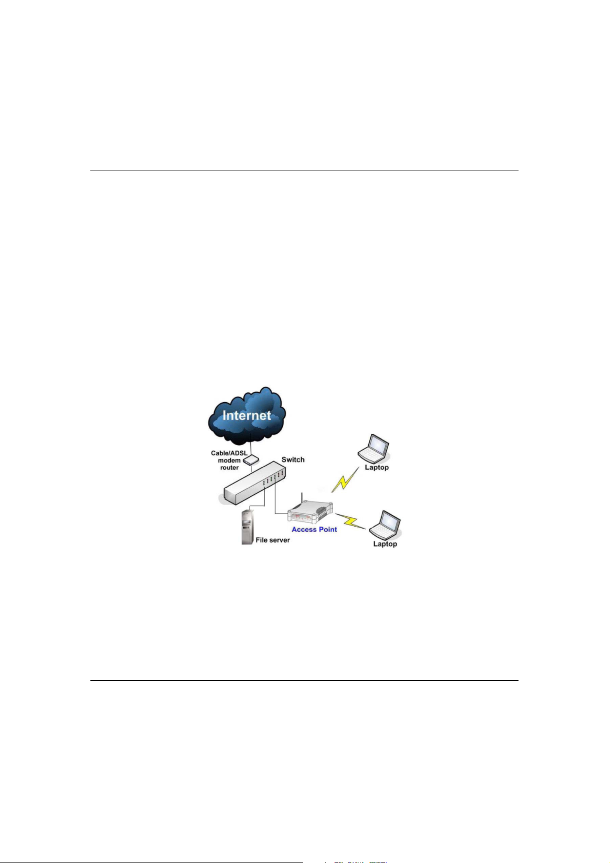
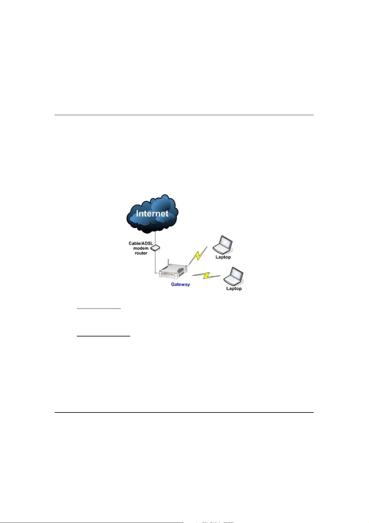
W
In the example above, the wireless users will be able to access the file server
connected to the switch through the access point in Access Point mode.
HHEENNTTOOUUSSEEWWHHIICCHHMMOODDE
W
The access point is versatile in the sense that it may operate in six different types
of modes: Access Point Mode, Client Mode, Point to Point, Point to Multiple
Point, Wireless Routing Client and Gateway.
This section presents a brief outline of the different network applications that
can be accommodated through the different modes of the access point.
E
A
CCCCEESSS
A
This is the default mode of your access point. The Access Point mode enables
you to bridge wireless clients to access the wired network infrastructure and to
communicate with each other.
P
S
P
OOIINNT
M
T
M
OODDE
E
4
Page 16
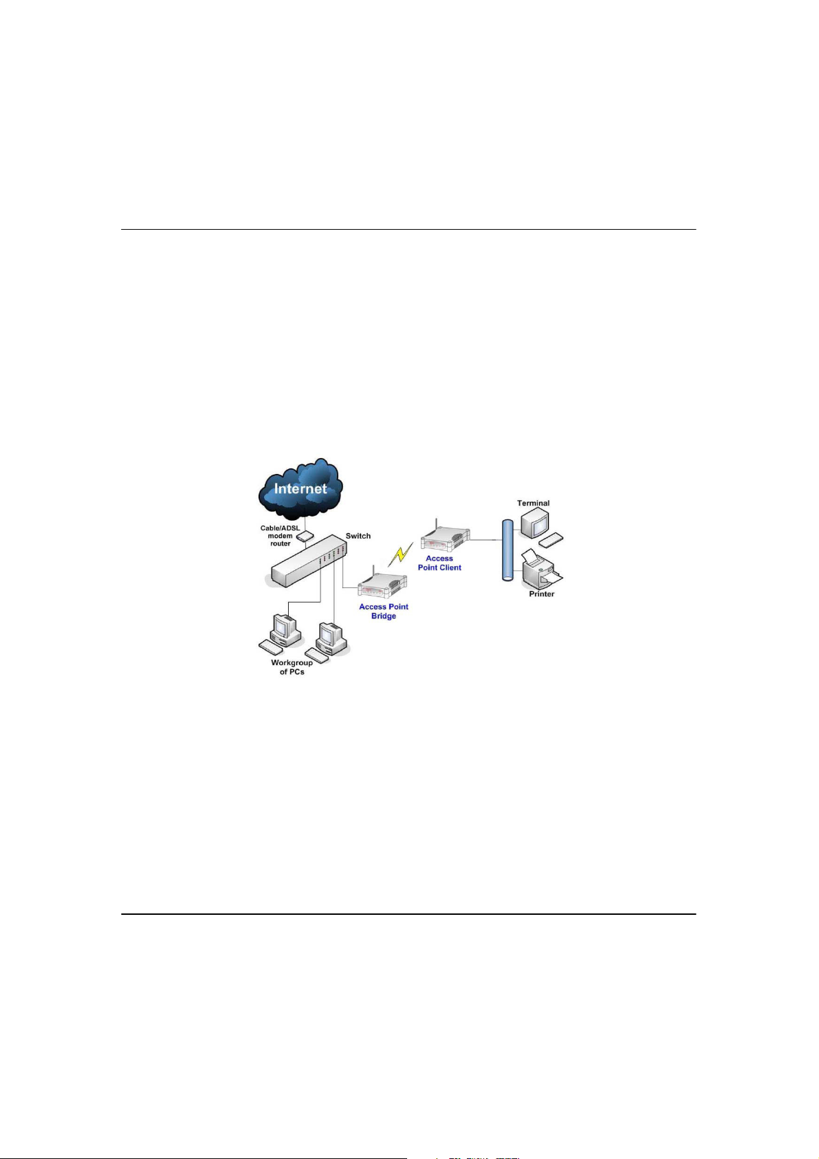
A
In the example above, the workgroup PCs will be able to access the printer
connected to the access point in Access Point Client mode.
CCCCEESSS
A
In Access Point Client mode, the device acts as a wireless client.
When connected to an access point, it will create a network link between the
Ethernet network connected at this client device, and the wireless and Ethernet
network connected at the access point.
In this mode it can only connect with an access point. Other wireless clients
cannot connect with it directly unless connected to the same access point allowing them to communicate with all devices connected at the Ethernet port
of the access point.
P
S
P
OOIINNT
C
T
C
LLIIEENNT
M
T
M
OODDE
E
5
Page 17

P
In the example above, you may configure two access points (AP) to perform
transparent bridging between two buildings
OOIINNTTTTO
P
In Point to Point mode, the access point allows point-to-point communication
between different buildings. It enables you to bridge wireless clients that are
kilometres apart while unifying the networks.
P
O
P
OOIINNT
M
T
M
OODDE
E
6
Page 18
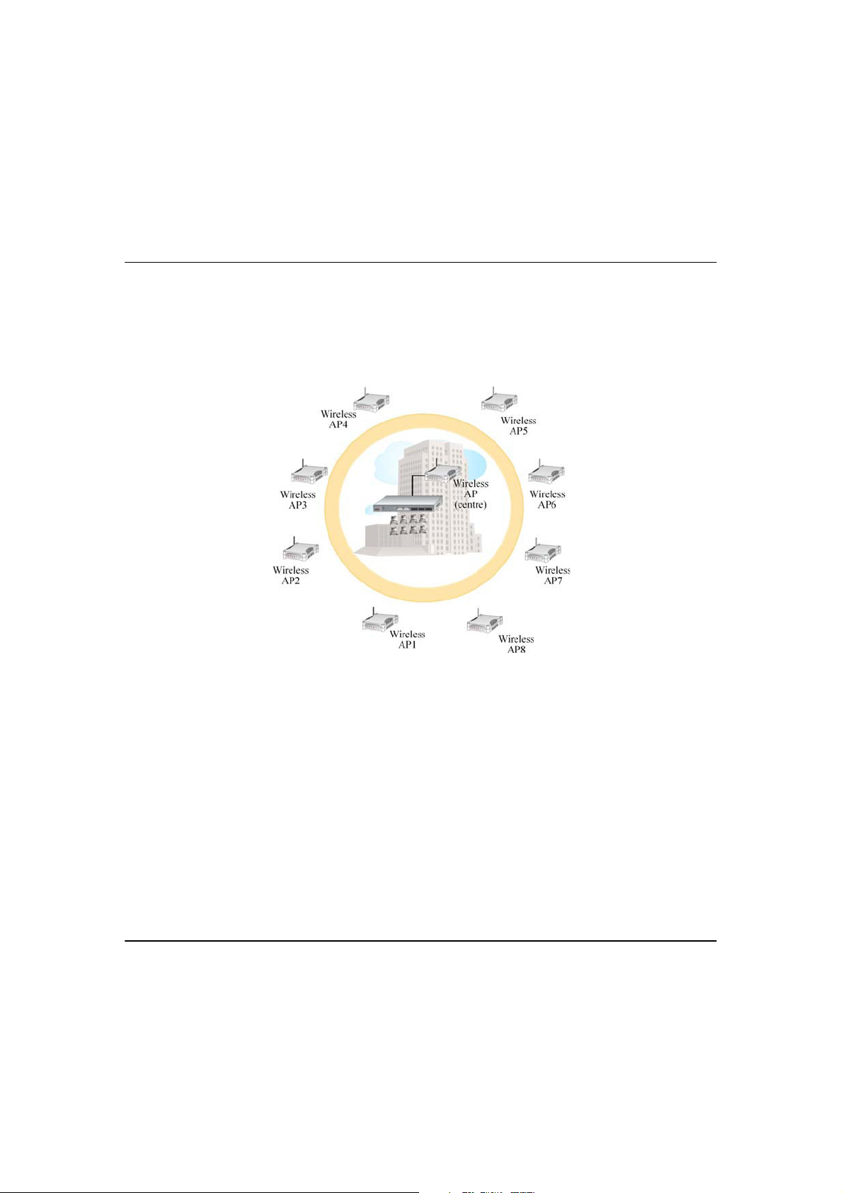
P
The above illustration describes how this mode operates.
OOIINNTTTTO
P
In Point to Multiple Point mode, this mode is similar to that of the Point-to-Point
mode. But the access point located at one facility is able to connect to up to 8
access points (AP) installed in any direction from that facility.
M
O
UULLTTIIPPLLEEPPOOIINNT
M
M
T
M
OODDE
E
7
Page 19
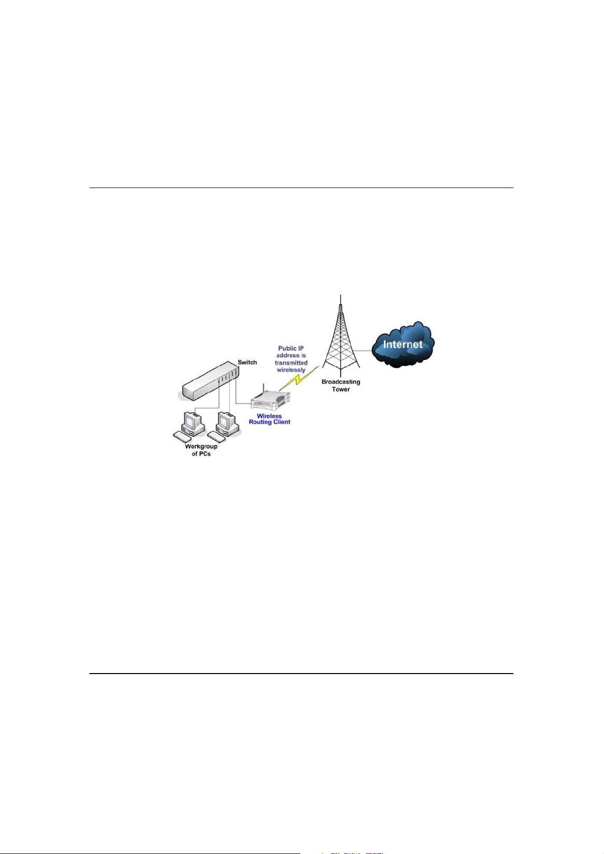
W
The above illustration describes how this mode operates.
IIRREELLEESSS
W
An application of this mode would be for the Ethernet port of the Wireless
Routing Client to be used for connection with other devices on the network
while access to the Internet would be achieved through wireless
communication with wireless ISP.
R
S
R
OOUUTTIINNG
C
G
C
LLIIEENNT
M
T
M
OODDE
E
8
Page 20
G
Static IP address
Use this type of connection if you have subscribed to a fixed IP address or to a
range of fixed IP addresses from your Internet Service Provider.
Dynamic IP address
When powered using this type of connection, the access point requests for an
IP address which will be automatically assigned to it by your Internet Service
Provider.
This type of connection applies for instance to:
! Singapore Cable Vision subscribers
! @HOME Cable Service users
AATTEEWWAAY
G
Or put it more simply, Broadband Internet sharing in a wireless network!
Since the access point supports several types of broadband connections, the
first step in setting up the access point as a Broadband Internet Gateway is to
identify the type of broadband Internet access you are subscribed to.
M
Y
M
OODDE
E
9
Page 21

PPP over Ethernet (PPPoE)
Select this type of connection if you are using ADSL services in a country utilising
standard PPP over Ethernet for authentication.
For instance:
If you are in Germany which uses T-1 connection or
If you are using SingNet Broadband or Pacific Internet Broadband in Singapore.
PPTP
Select this type of connection if you are using ADSL services in a country utilising
PPTP connection and authentication.
L2TP
Short for Layer Two (2) Tunneling Protocol, an extension to the PPP protocol that
enables ISPs to operate Virtual Private Networks (VPNs). L2TP merges the best
features of two other tunneling protocols: PPTP from Microsoft and L2F from
Cisco Systems.
10
Page 22
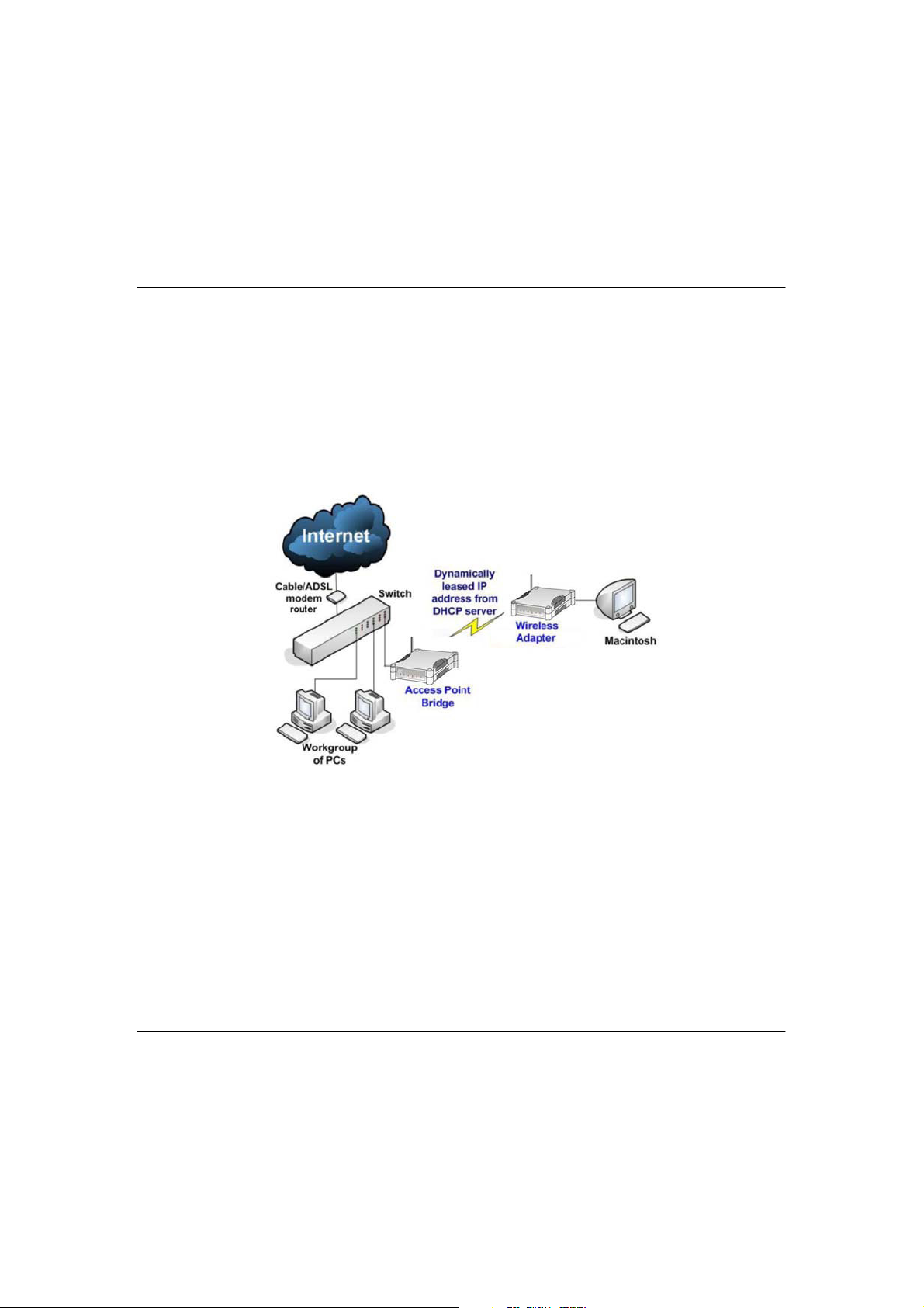
W
IIRREELLEESSS
W
Similarly to the Access Point Client mode, the access point used in this mode, is
able to communicate wirelessly with another access point to perform
transparent bridging between two networks.
However here, the Wireless Adapter connects a single wired workstation only.
No client software or drivers are required while using this mode.
A
S
A
DDAAPPTTEER
M
R
M
OODDE
E
11
Page 23
12
CChhaapptteerr22::HHaarrddwwaarreeIInnssttaallllaattiioon
n
S
S
EETTUUP
P
R
R
EEQQUUIIRREEMMEENNTTS
S
Before starting, please verify that the following is available:
! CAT5/5e networking cable
! At least one computer is installed with a Web browser and a wired or
wireless network interface adapter
! TCP/IP protocol is installed and IP address parameters are properly
configured on all your network’s nodes
H
H
AARRDDWWAARRE
E
I
I
NNSSTTAALLLLAATTIIOON
N
The access point can be powered using either the power adapter provided or
a PoE Injector. The installation process for both options is described below.
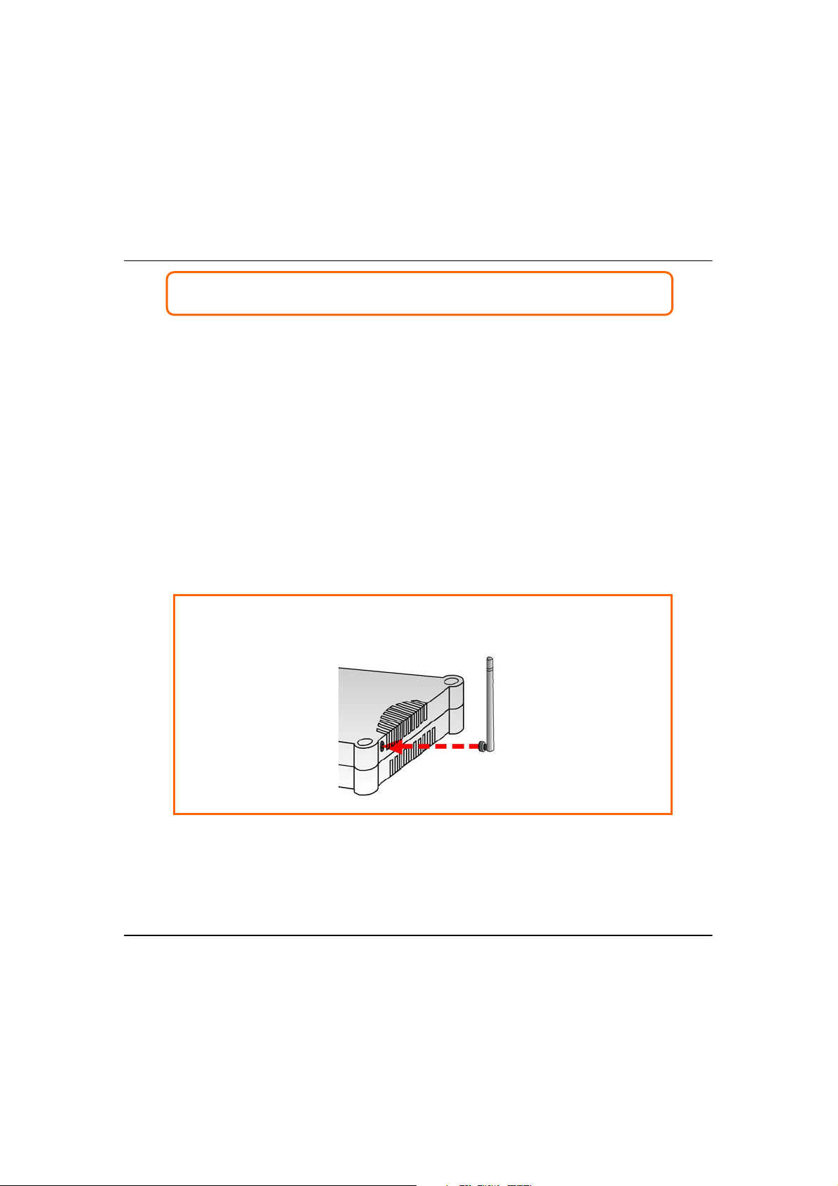
OOPPTTIIOONNO
O
NNE
E
::U
U
SSIINNGGPPOOWWEERRAADDAAPPTTEERRTTOOSSUUPPPPLLYYPPOOWWEERRTTOOTTHHEEUUNNIIT
T
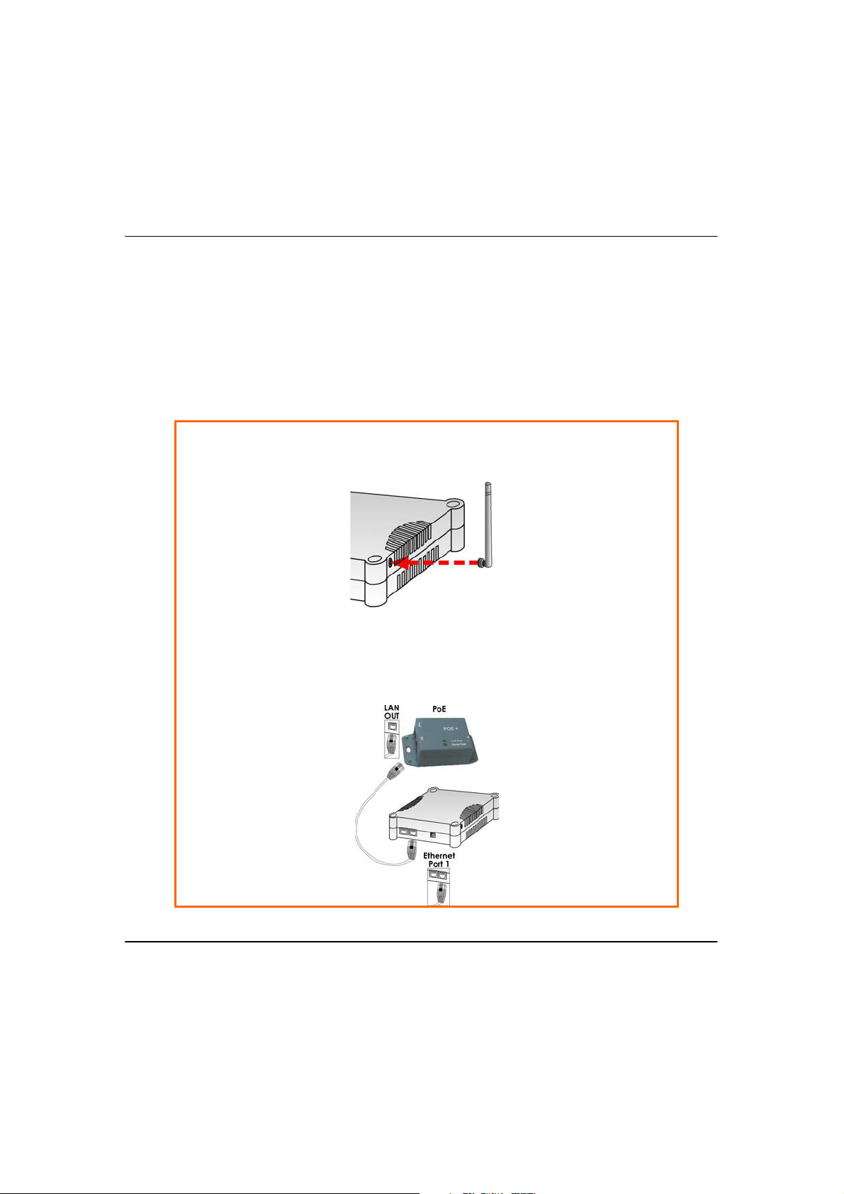
SStteepp11:
:
Connect the external antenna to the SMA connector of the access point.
Page 24
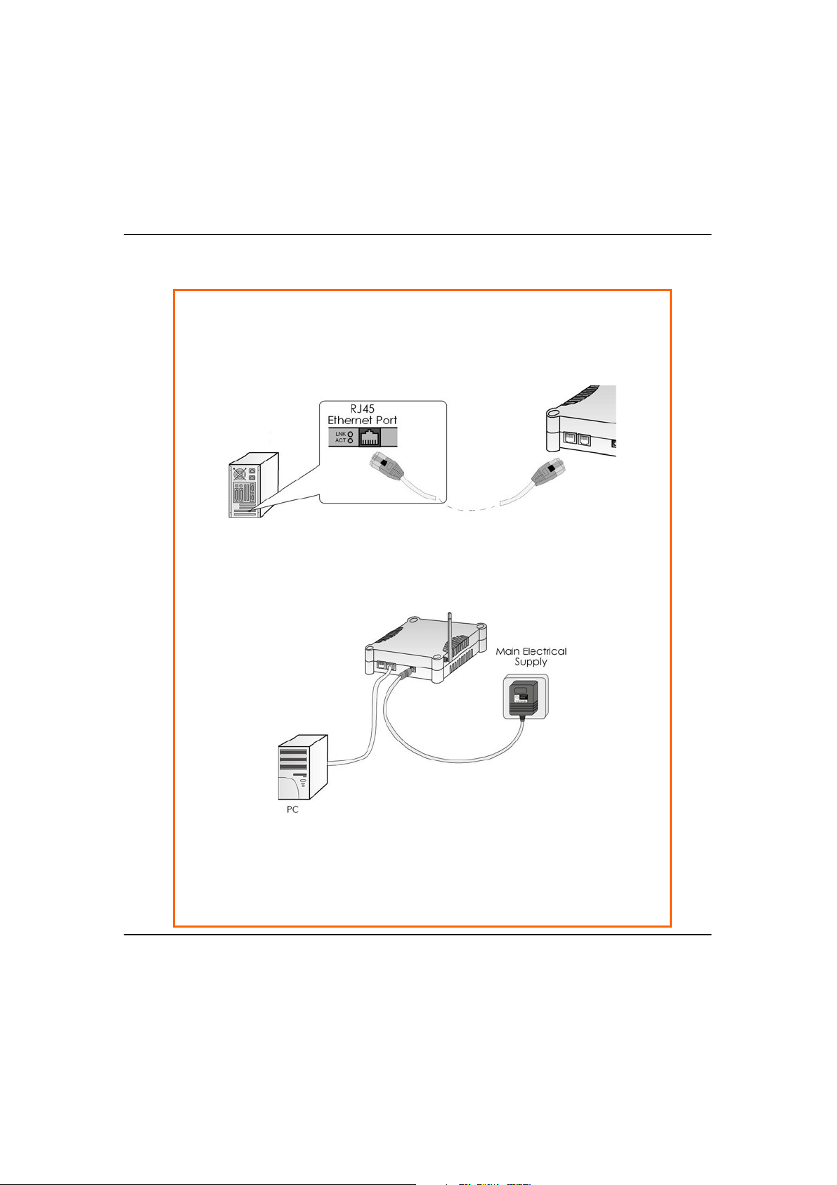
SStteepp33:
:
Attach the power adapter to the main electrical supply, and connect the
power plug into the socket of the access point.
SStteepp44:
:
Turn ON the power supply and power ON your PC. Notice that the LEDs: Power
and Port 1 or 2 (depending on which port you have connected the RJ45
Ethernet cable to) have lighted up. This indicates that connection has been
established successfully between your access point and your PC.
PC
SStteepp22:
Insert one end of the Ethernet cable to any of the Ethernet ports on your
access point, and the other end of the cable to your PC’s Ethernet network
adapter.
:
13
Page 25
T
SStteepp22:
:
Use an RJ45 Ethernet cable to connect one end of the cable to the LAN OUT
port of the Injector and the other end to Ethernet port 1 of the access point.
U
O
OOPPTTIIOONNT
The access point is fully compatible with a Power-Over-Ethernet (PoE) kit. A PoE
accessory supplies operational power to the wireless AP via the Ethernet cable
connection.
Users who have already purchased a PoE and who wish to use it to supply
power to the access point may follow the installation procedures shown below:
WWO
::U
SSIINNG
P
E
G
O
O
TTOOSSUUPPPPLLYYPPOOWWEERRTTOOTTHHEEUUNNIIT
P
E
T
SStteepp11:
Connect the external antenna to the SMA connector of the access point.
:
14
Page 26
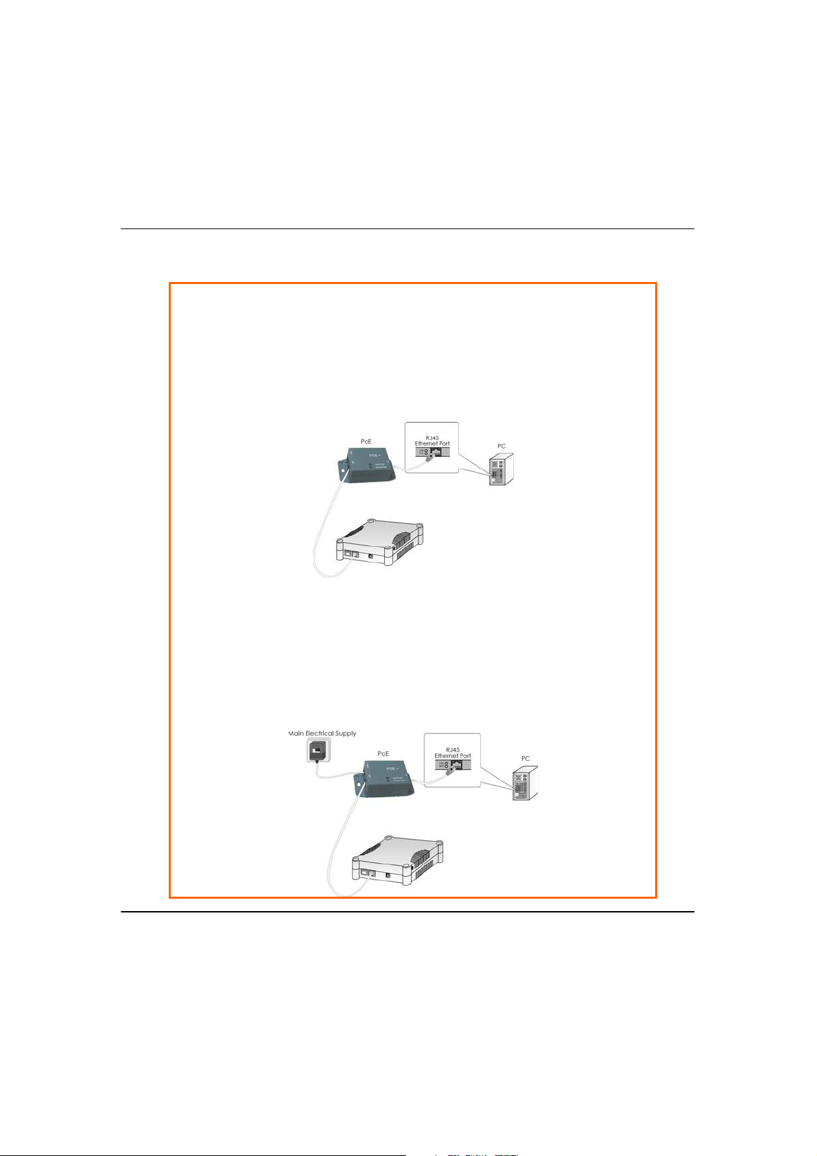
SStteepp33:
SStteepp44:
:
Connect the power adapter supplied in the PoE kit to the main electrical
supply and the power plug into the socket of the injector.
Note:
The voltage and current supplied to the power adapter and the PoE kit power
adapter are different. Do not interchange the power adapters.
Next, connect the RJ45 Ethernet cable attached to the PoE Injector to your
PC’s Ethernet network adapter.
Once you have finished configuring your access point, you can connect the
PoE Injector’s RJ45 Ethernet cable to your network device, such as to a switch
or hub.
:
15
Page 27

SStteepp55:
Turn on your power supply. Notice that the Power LED has lighted up. This
indicates that the access point is receiving power through the PoE Injector.
Notice also that the corresponding port LEDs have lighted up. This indicates
that connection between your access point and your PC has been
established.
:
16
Page 28
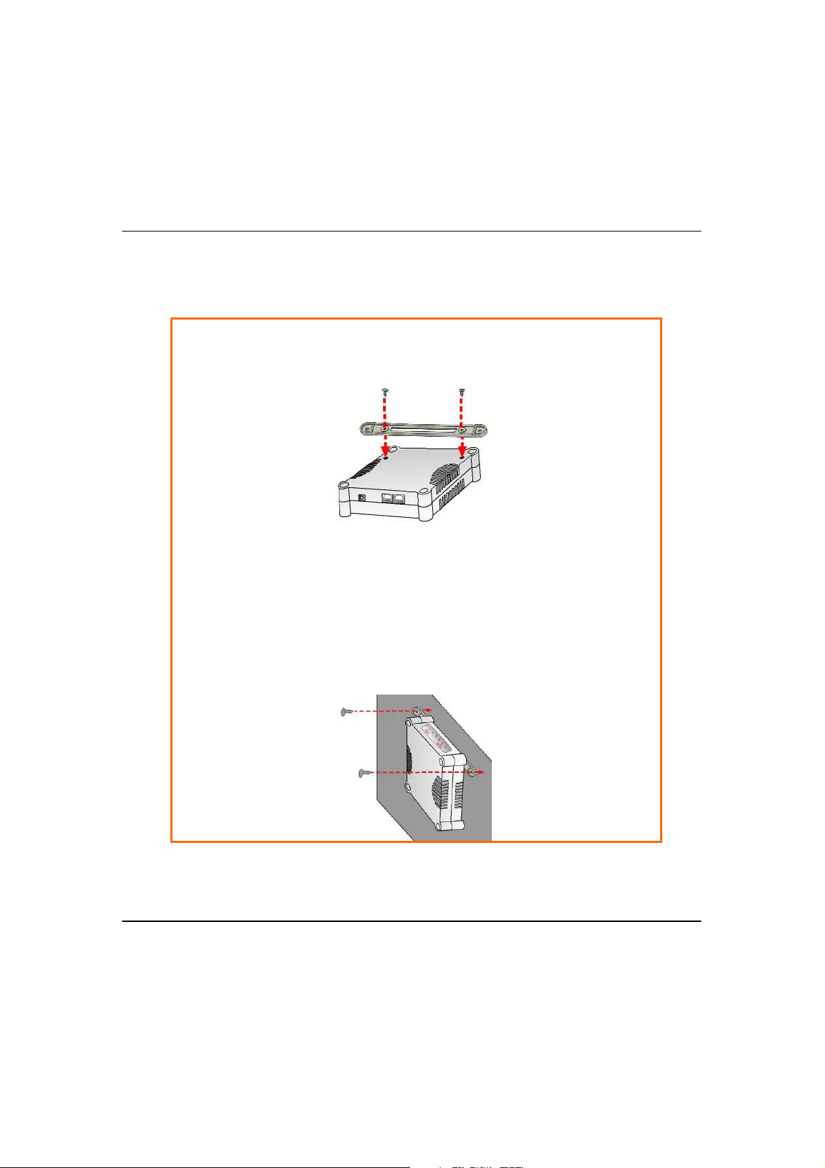
O
SStteepp22:
:
Align the unit and mount to the wall.
Use the mount as a guide, make 2 marks and drill 2 holes into the wall.
SStteepp33:
:
Next, secure the unit and mount to the wall.
PPTTIIOONNAAL
O
M
L
OOUUNNTTIINNGGOONNTTHHE
::M
W
E
L
AALLL
W
SStteepp11:
Screw the mount onto the unit.
:
17
Page 29

CChhaapptteerr33::AAcccceessssttooWWeebb--bbaasseed
d
U
e
C
C
G
OONNFFIIG
IInntteerrffaacce
There are two methods to access to the web-based Interface of your access
point:
!!TThhrroouugghhoouurrUUttiilliittyy––uuCCoonnffiig
You can access to the web-based interface directly without the need to
assign a different IP address to your PC.
t
!!BByyeenntteerriinnggt
EExxpplloorreer
You need to assign an IP address to your PC, such as 192.168.168.x, where x
can take any value from 2 to 254, so that it is in the same subnet as Access
point.
A
CCCCEESSSSTTOOTTHHE
A
The powerful uConfig utility has been designed to give you direct access to the
Web interface.
SStteepp11:
Insert the Product CD into your CD-ROM drive. The CD will run automatically.
SStteepp22:
From the UUttiilliittiieess section, select to install the uuCCoonnffiigg utility to your hard disk.
:
:
hheeIIPPaaddddrreessssooffAAcccceessssppooiinnttiinntthheeaaddddrreessssbbaarrooffIInntteerrnneet
r
E
W
EEBBIINNTTEERRFFAACCEEWWIITTHHU
W
g
t
18
Page 30
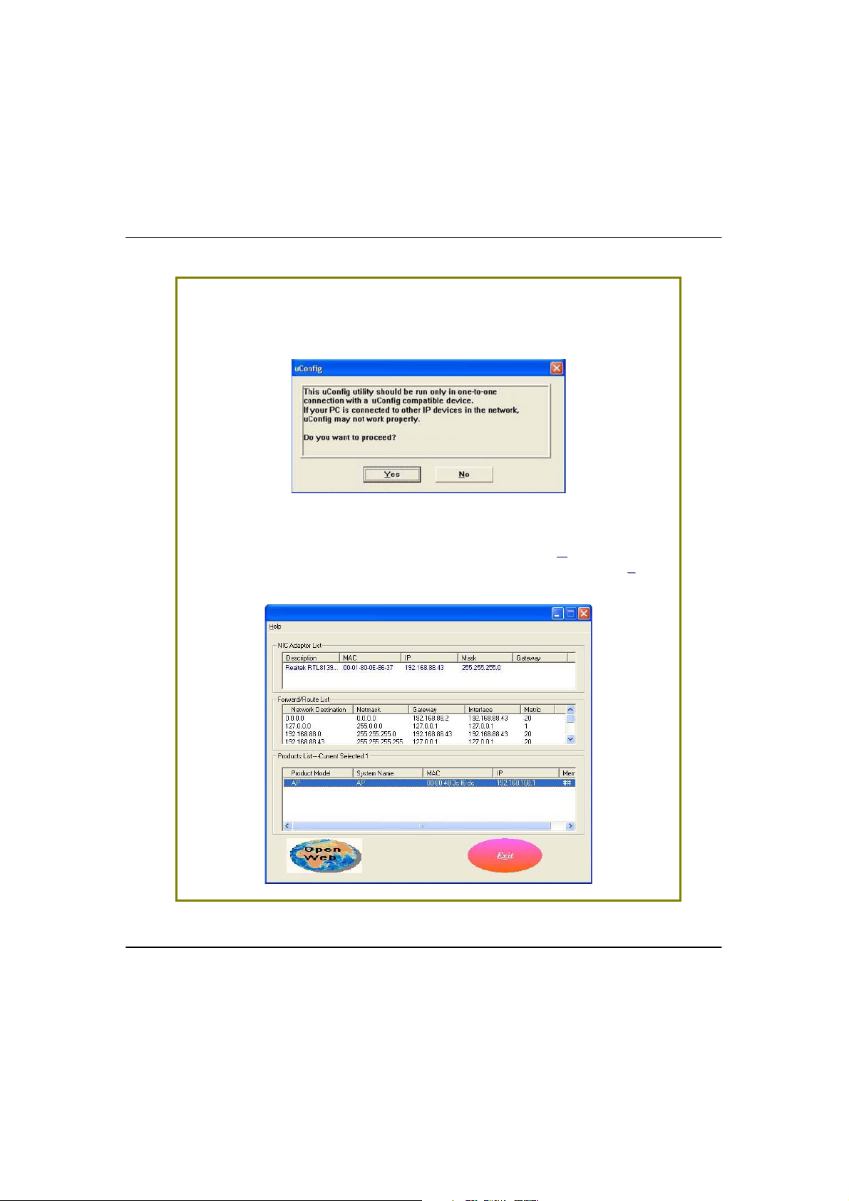
SStteepp33:
SStteepp44:
:
Select the access point in the products list and click on the OOppeennWWeebb button.
To retrieve and display the latest device(s) in the list, click on the RReeffrreesshh
button.
When the utility has been installed, double-click on the uuCCoonnffiigg icon. The
following screen will appear, click on the
:
s button to proceed.
YYees
19
Page 31

SStteepp55:
SStteepp66:
:
At the login page, press the LLOOGGIINN!! button to enter the configuration page.
The default password is “password”.
Do not exit the uConfig program while accessing to the web-based interface.
This will disconnect you from the device. Click on the
:
K button to proceed.
OOK
20
Page 32

SStteepp77:
You will then reach the home page of your access point’s web-based
interface.
:
21
Page 33

M
AANNUUAALLAACCCCEESSSSTTOOWWEEB
M
E
XXPPLLOORREER
E
For this method, you need to assign an IP address to your PC so that it belongs
to the same subnet as your access point. In this example, we are using Windows
XP for illustration. For Windows 98/98SE/2000/NT/ME, kindly refer to Appendix II
“TCP/IP Configuration”.
R
B
-
BBAASSEEDDIINNTTEERRFFAACCEEVVIIA
-
A
I
NNTTEERRNNEET
I
T
SStteepp11:
Go to your desktop, right-click on MMyyNNeettwwoorrkkPPllaacceess icon and select
PPrrooppeerrttiiees
SStteepp22:
Go to your network adapter icon, right click and select PPrrooppeerrttiieess.
:
s.
:
22
Page 34

SStteepp33:
SStteepp44:
:
Select the radio button for UUsseetthheeffoolllloowwiinnggIIPPaaddddrreessss. Enter the IP Address
and Subnet Mask as 192.168.168.x and 255.255.255.0, where x can be any
number from 2 to 254, except 1. In this example, we are using 192.168.168.160
as the static IP Address.
Highlight IInntteerrnneettPPrroottooccooll((TTCCPP//IIPP)) and click on the PPrrooppeerrttiieess button.
:
23
Page 35

SStteepp55:
Your PC is now ready to configure your access point.
SStteepp77:
:
Launch your Web browser. Under the TToooollss tab, select IInntteerrnneettOOppttiioonnss.
Click on the OOKK button to close all windows.
:
SStteepp66:
Next, in order to check if the IP address has been correctly assigned to your
PC, go to
command ipconfig/all.
:
t menu, AAcccceessssoorriieess, select CCoommmmaannddPPrroommpptt and type the
SSttaarrt
24
Page 36

SStteepp88:
Open the CCoonnnneeccttiioonnss tab and in the LLAANNSSeettttiinnggss section, disable all the
option boxes. Click on the
:
K button to update the changes.
OOK
SStteepp99:
At the AAddddrreessss bar, enter http://192.168.168.1 and press EEnntteerr on your
keyboard.
SStteepp1100:
At the login page, click on the LLOOGGIINN!! button to enter the configuration
pages.
:
:
25
Page 37

26
You will then reach the home page of your access point’s Web interface.
Page 38

CChhaapptteerr44::CCoommmmoonnCCoonnffiigguurraattiioon
n
This chapter illustrates the following features, which are available in ALL
operating modes of your access point, unless stated otherwise.
!!MMaannaaggeemmeennttPPoorrt
!!WWLLAANNBBaassiiccSSeettuup
!!WWLLAANNSSeeccuur
!!SSTTPPSSeettuup
!!SSNNMMP
!!MMAACCFFiilltteerriinng
!!AAnntteennnnaaAAl
M
AANNAAGGEEMMEENNT
M
This section shows you how to customize the parameters of your access point to
suit the needs of your network. It also explains how to make use of the built-in
DHCP server of your access point.
p
P
t
p
y
r
iitty
g
liiggnnmmeenntt
T
P
OORRT
P
T
S
S
EETTUUP
P
the
27
Page 39

S
SStteepp22:
:
Click on the AAppppllyy button to save your new parameters.
EETTTTIINNGGUUPPYYOOUUR
S
You can opt to adjust the default values of your access point and customize
them to your network settings.
R
N
LLAAN
SStteepp11:
Click on MMaannaaggeemmeennttPPoorrtt from the CCOONNFFIIGGUURRAATTIIOONN menu.
In the MMaannaaggeemmeennttPPoorrttSSeettuupp page, refer to the table below to replace the
default settings of Access point with appropriate values to suit the needs of
your network.
:
28
Page 40

This table describes the parameters that can be modified in the Management
Description
IP Address When the DHCP server of the access point is enabled (unless you
set a different DHCP Gateway IP Address), this LAN IP Address
would be allocated as the Default Gateway of the DHCP client.
The IP address of your Access point is set by default to
192.168.168.1.
Network Mask The Network Mask serves to identify the subnet in which your
Access point resides. The default network mask is 255.255.255.0.
Management
Gateway IP
(Optional) As a bridge Access Point, the access point does not
usually communicate with devices on other IP subnets. However,
the Management Gateway here acts as the equivalent of the
Default Gateway of a PC, to allow the access point to
communicate with devices on different subnets. For instance, if
you want to access the access point from the Internet or from a
router on the LAN, enter the router IP address in the
Management Gateway IP field.
The Management Gateway IP address of your access point is set
to nil by default.
The next two fields (DHCP Start IP Address and DHCP End IP Address) allow you to define
the range of IP addresses from which the DHCP Server can assign an IP address to the
LAN.
DHCP Start IP
Address
This is the first IP address that the DHCP server will assign. The
value that you input here should belong to the same subnet as
your access point. For example, if the IP address and network
mask of your access point are 192.168.168.1 and 255.255.255.0
respectively, the DHCP Start IP Address should be 192.168.168.X,
where X can take any value from 2 to 254. It is pre-set to
192.168.168.100.
DHCP End IP
Address
This is the last IP address that the DHCP server can assign. It
should also belong to the same subnet as your access point. For
instance, if the IP address and network mask of your access point
are 192.168.168.1 and 255.255.255.0 respectively, the DHCP End
IP Address should be 192.168.168.X, where X can take any value
from 2 to 254. It is pre-set as 192.168.168.254.
Port Setup page.
Parameters
29
Page 41

Description
DHCP Gateway IP
Address
Though usually, the DHCP server also acts as the Default
Gateway of the DHCP client, the access point gives you the
option to define a different Gateway IP Address, which will be
allocated as the Default Gateway IP of the DHCP client. The
DHCP client will thus receive its dynamic IP address from the
access point but will access to the Internet or to the other LAN
through the Default Gateway defined by the DHCP Gateway IP
Address.
For instance, if the access point is used in Access Point Client
mode and connects to an Internet gateway,
X, a PC wired to
the access point will be unable to obtain a dynamic IP address
directly from
X. But if you can enable the DHCP server of the
access point and set the IP address of
X as the DHCP Gateway IP
Address, the PC will then obtain its IP address from the access
point and access the Internet through
X.
Always use these
DNS servers
Enable this checkbox if you want the access point to only use
the DNS server(s) you have specified below.
Primary DNS IP
Address
Your ISP usually provides the IP address of the DNS server.
Secondary DNS IP
Address
This optional field is reserved for the IP address of a secondary
DNS server.
DHCP Server If you disable the DHCP server, you will need to manually
configure the TCP/IP parameters of each computer in your
network.
Parameters
30
Page 42

T
The DHCP Active Leases table displays:
! The Host Name of the DHCP client
! The IP Address that has been allocated to the DHCP client
! Its Hardware (MAC) Address
! The Lease Expired Time.
NOTE
Invalid date and time displayed in the Lease Expired Time column
indicates that the clock of your access point has not been properly
set. Please refer to the SYSTEM TOOLS section for more details on
how to set the system clock.
OOVVIIEEWWTTHHEEAACCTTIIVVE
T
The following will guide you to a page display of the active IP address leases
that have been allocated by the built-in DHCP server of Access point.
E
DDHHCCP
P
LLEEAASSEES
S
SStteepp11:
Click on MMaannaaggeemmeennttPPoorrtt from the CCOONNFFIIGGUURRAATTIIOONN menu.
SStteepp22:
Go to the AAddvvaanncceeddDDHHCCPPSSeerrvveerrOOppttiioonnss section, click on the SShhoowwAAccttiivvee
DDHHCCPPlleeaasse
:
:
e
s button.
s
31
Page 43

T
SStteepp22:
:
Click on AAdddd button.
OORREESSEERRVVEESSPPEECCIIFFIIC
T
Making an IP address reservation lets you inform the DHCP server to exclude
that specific address from the pool of free IP addresses it draws on for dynamic
IP address allocation.
For instance, if you set up a publicly accessible FTP/HTTP server within your
private LAN, while that server would require a fixed IP address, you would still
want the DHCP server to dynamically allocate IP addresses to the rest of the
PCs on the LAN.
The following shows you how to reserve a particular IP address.
P
C
AADDDDRREESSSSEESSFFOORRPPRREEDDEETTEERRMMIINNEED
IIP
D
DDHHCCP
P
CCLLIIEENNTTS
S
SStteepp11:
From the AAddvvaanncceeddDDHHCCPPSSeerrvveerr Options section, click on the DDHHCCPPSSeerrvveerr
RReesseerrvvaattiioonns
:
s button.
32
Page 44

SStteepp33:
The DDHHCCPPSSeerrvveerrRReesseerrvvaattiioonnss page will then be refreshed to illustrate the
currently reserved IP addresses.
Fill in:
The host portion of the IP Address to reserve.
The Hardware Address, in pairs of two hex values
:
Press the
y button to make your new entry effective.
AApppplly
33
Page 45

D
SStteepp22:
:
Click on the DDeelleettee button.
The DDHHCCPPSSeerrvveerrRReesseerrvvaattiioonnss table will then be refreshed to reflect your
changes.
E
EELLEETTE
D
If you do not need the DHCP server to reserve an IP address anymore, you
can delete the DHCP Server Reservation.
DDHHCCPPS
S
EERRVVEERRRREESSEERRVVAATTIIOON
N
SStteepp11:
Click on the reserved IP address that you wish to delete, e.g. 192.168.168.20.
:
34
Page 46

P
S
WWLLAANNS
This section shows how to perform the following functions:
Basic
This function performs a basic setup of the wireless modes of operation: Access
Point mode, Access Point Client mode and other operating modes.
EETTUUP
:
Security
This function performs data encryption and protection for the access point.
Kindly refer to Chapter 5 on WLAN Security for details.
Advanced
This function furthers the basic configuration of the access point by setting the
system’s additional parameters: Wireless Pseudo VLAN, WDS Configuration and
Long Distance Parameters.
Kindly refer to Chapter 6 on Wireless Extended Features for details.
Statistics
This function uses the Scan Feature to monitor and interpret the statistics data
collected.
MAC Filtering
MAC Filtering acts as a security measure by restricting the users accessing to
the network through their MAC address.
Antenna Alignment
It is a tool for aligning outdoor antenna between 2 access points over long
distances. The signal level can be checked from the web page and also from
the DIAG LED indicator.
:
:
:
(only applicable to Access Point mode):
:
35
Page 47

T
OOCCOONNFFIIGGUURREETTHHE
T
The following will guide you to configure the basic setup of the wireless mode
you have selected.
B
E
AASSIICCSSEETTUUPPOOFFTTHHEEWWIIRREELLEESSSSMMOODDE
B
E
SStteepp11:
Click on WWLLAANNSSeettuupp from the CCOONNFFIIGGUURRAATTIIOONN menu. You will see the submenus expanded under
The default operating mode of Access point is the Access Point mode.
:
WWLLAANNSSeettuup
p. Click on BBaassiicc.
36
Page 48

SStteepp22::((OOppttiioonnaall::CChhaannggeeCCuurrrreennttmmooddee)
If you wish to change the current mode of your access point, click on
CChhaanngge
access the setup page of your selected mode. Then you are prompted to
reboot the access point so as to effect the mode setting.
e, select your OOppeerraattiioonnMMooddee and click on the AAppppllyy button to
)
37
Page 49

SStteepp33:
If you wish to set the access point in the PPooiinntt--ttoo--PPooiinntt mode, click on CChhaannggee
to select PPooiinnttttooPPooiinntt, and then you will see the page below.
Enter the parameters in their respective fields, click on the AAppppllyy button and
reboot your device to let your changes take effect.
:
Note that the
that of the Access Point mode.
WWLLAANNBBaassiiccSSeettuup
p page for the Client mode is different from
38
Page 50

If you wish to set the access point in the PPooiinnttttooMMuullttiipplleePPooiinntt mode, click on
To create a new peer MAC, click on the PPeeeerrMMAACCLLiisstt button. The page will
appear. ( Please take note that PtMP stands for Point to Multiple Point ).
Click on AAdddd, and then you are prompted to key in HHaarrddwwaarreeAAddddrreessss and
CCoommmmeennt
t.
CChhaanngge
below.
e to select PPooiinnttttooMMuullttiipplleePPoo
t, and then you will see the page
iinnt
39
Page 51

This table describes the parameters that can be modified in the WWLLAANNBBaassiicc
Description
The Current Mode The default operating mode of the access point is the
Access Point mode. The access point can operate in 6
modes:
! Access Point
! Client
! Point to Point
! Point to Multiple Point
! Wireless Routing Client
! Gateway
! Wireless Adapter
You can toggle the mode by clicking on the CChhaannggee
button.
ESSID Enter a preferred name for the wireless network. Your
wireless clients must be configured with the same ESSID.
This case-sensitive entry can consist of a maximum of 32
characters.
Site Survey
A list of wireless devices that are detected by your
access point in the WLAN. Information such as MAC
address, channel, SSID, algorithm and signal strength can
be found in the listing.
This feature is supported by the Access Point Client and
Wireless Routing Client modes.
Wireless Profile A selection of network environment types in which to
operate the access point:
!!880022..1111aaoonnlly
y
This mode supports wireless A clients with data rates of up
to 54Mbps in the frequency range of 5.4GHz.
!!880022..1111bboonnlly
y
This mode supports wireless B clients with data rates of up
to 11Mbps in the frequency range of 2.4GHz.
p page.
SSeettuup
Parameters
40
Page 52

!!880022..1111bb//ggmmiixxeed
This mode supports both wireless B and G clients.
d
!!880022..1111ggoonnlly
This mode supports wireless-G clients that offer
transmission rates of up to 54Mbps in the 2.4GHz
frequency band.
Peer Mac ( Only in
Point-to-Point
mode )
Peer MACs (Only
in Point-toMultiple Point
mode)
Country Choose the Country where you are located.
Channel This option allows you to select a frequency channel for
This mode can support more than one access point. This
feature allows you to create a new peer MAC for
another access point so that the router operating in the
access point mode can connect to another access
point.
This mode can support multiple access points. This
feature allows you to create multiple peer MAC
addresses so that the router can connect to multiple
access points.
the wireless communication. This parameter is only
available in the Access Point, Point to Point and Point to
Multiple Point modes.
Select SmartSelect to automatically scan and
recommend the best channel that the access point can
utilize.
y
Tx Rate Allow you to choose the rate of data transmission from
1Mbps to Fully Auto.
Closed System The access point will not broadcast its WLAN name
(ESSID) when Closed system is enabled. By default
Closed system is disabled.
Channel Survey
A list of channels that are detected by your access point
in the WLAN. Information such as frequency, channel,
MyQuality, NeighQuality, APCount and
Recommendation can be found in the listing.
The Access Point and Gateway modes support this
feature.
41
Page 53

S
The SSiitteeSSuurrvveeyy provides a list of the MMAACCaaddddrreesssseess((BBSSSSIIDD)) andSSSSIIDD of
neighbouring access points detected, the
CChhaan
n (channels), AAuutthh
(Authentication), AA
l
lgg (Algorithm) used, and the strength of the SSiiggnnaall
received.
CCAANNFFOOR
S
O
Y
NNLLY
((O
S
S
R
E
IITTE
S
F
C
R
OOR
F
C
UURRVVEEY
S
LLIIEENNT
M
T
M
Y
OODDEEAANND
D
W
IIRREELLEESSS
W
R
S
R
OOUUTTIINNG
C
M
G
C
LLIIEENNT
T
M
OODDE
)
E
)
SStteepp11:
In the MMooddeeSSeettuupp page, click on the SSiitteeSSuurrvveeyy button.
:
42
Page 54

SStteepp22:
Description
Bssid In an infrastructure wireless network, the BSSID refers to
the wireless MAC address of the access point.
SSID Refers to the network name that uniquely identifies the
network to which the access point is connected.
Chan Refers to the channel being used for transmission.
Auth Refers to the types of authentication, such as WPA, WPA-
Personal, etc being used by the access point.
Alg Refers to the types of algorithm, such as WEP, TKIP, etc
being used by the access point.
Signal Describes the strength of the signal received in
percentage.
To connect the client to one of the access points detected:
Select the radio button corresponding to the access point you want to
connect to.
:
SStteepp33:
Click on the AAppppllyy button to effect the change and return to the setup
page.
SStteepp44:
Click on the RReeffrreesshh button to update this screen.
This table describes the read-only parameters of neighbouring access points
that can be viewed from the Site Survey page.
Parameters
:
:
43
Page 55

NOTE
The purpose of using Site Survey is to scan and display all access
points based on the current security setting of your access point.
For instance, the following information supplied by the Site Survey
according to the security setting is explained:
! If the security mode is set to None or WEP, the scan will show
all available access points that have no security or WEP
security
! If the security mode is set to WPA-Personal, the scan will show
all available access points having all types of security from no
security, WEP security to WPA-Personal security.
44
Page 56

S
TheLLiinnkkIInnffoorrmmaattiioonn table illustrates the following data:
HHOOW
S
O
((O
W
NNLLY
L
IINNK
L
F
Y
OOR
F
I
K
NNFFOORRMMAATTIIOON
I
C
R
T
LLIIEENNT
C
M
OODDEEAANND
M
N
W
D
W
IIRREELLEESSS
R
S
R
OOUUTTIINNG
C
G
C
LLIIEENNTTMMOODDE
)
E
)
SStteepp11:
To view the connection status when the client is linked to another access
point, click on the
:
SShhoowwLLiinnkkIInnffoorrmmaattiioon
n button.
45
Page 57

This table describes the parameters that can be viewed from the LLiinnkk
Description
State Refers to the MAC address of the BSS (AP to which the
client is connected).
Current Channel The channel that is being presently used for transmission.
Tx Rate The rate of data transmission in Mbps.
Signal Strength Given in percentage, showing the intensity of the signal
received.
IInnffoorrmmaattiioon
Parameters
n page.
46
Page 58

S
The CChhaannnneellSSuurrvveeyy provides a list of the FFrreeqq (frequency) and CChhaannnneell of
the access point detected, the
AAPPCCoouunntt,MMyyQQuuaalliitty
y (your access point’s
interference from your access point’s channel signal) received and
NNeeiig
g
hhQQuuaalliitty
y (interference from the neighbouring access points’ channel
signals) received.
CCAANNFFOOR
S
(
AAVVAAIILLAABBLLE
(
Channel Survey provides a list of all channels that are supported by the access
point. This feature will show relative interference of all channels and
recommend the least congested channel.
When the users want to scan for and find the best channel, they can use
Channel Survey.
R
E
C
HHAANNNNEEL
C
F
OOR
F
R
A
CCCCEESSS
A
S
L
S
UURRVVEEY
P
S
P
Y
OOIINNT
M
T
M
OODDEEAANND
D
G
AATTEEWWAAY
G
M
M
OODDE
)
E
)
Y
SStteepp11:
In the MMooddeeSSeettuupp page, click on the CChhaannnneellSSuurrvveeyy button.
:
47
Page 59

The values indicate the level of interference.
The higher the value, the higher the interference.
If the value is zero, there is no interference.
SStteepp55:
:
To connect the client to one of the channels detected, select the radio
button corresponding to the channel you want to connect to.
SStteepp66:
:
Click on the AAppppllyy button to effect the change and return to the setup
page.
SStteepp77:
:
Click on the RReeffrreesshh button to update this screen.
48
Page 60

This table describes the read-only parameters of all channels that can be
Description
Freq Refers to the frequency of the channel at which your
access point is operating.
Channel Refers to the channel of the access point being used for
transmission depending on its origin of country.
MyQuality
Indicates the interference level of the respective channel
with this AP.
The lower the value, the less interference.
APCount Refers to the total number of access points operating at
the current channel.
NeighQuality
Indicates the interference level with those discovered
APs at those respective channels.
The lower the value, the less interference.
Recommendation
Indicates the best channel for the AP device to use in its
current environment.
viewed from the Channel Survey page.
Parameters
49
Page 61

A
SStteepp22:
:
If you wish to specify the MAC address of the remote AP, key in the field next
to
RReemmootteeAAPPAAddddrreessss((ooppttiioonn)
), followed by executing the SSttaarrtt button. Then
the pop-up status screen will show up, allowing you to monitor the signal
strength received from the remote access points.
If there is no specified AP with
its MAC address you have
keyed in, the screen below will
show on the right. To abort or
key in the MAC address of the
other available remote AP,
click on the
SSttoop
p button.
NNTTEENNNNA
A
(
AAVVAAIILLAABBLLE
(
The Antenna Alignment feature in the access point is designed to precisely
align the antenna over such a long distance so that the connectivity
communication between your access point and another remote or
neighbouring access point could be improved as indicated by higher signal
strength.
A
A
A
F
E
LLIIGGNNMMEENNT
A
R
L
OOR
LLL
F
A
M
M
T
OODDEES
)
S
)
SStteepp11:
Click on WWLLAANNSSeettuupp from the CCOONNFFIIGGUURRAATTIIOONN menu. You will see the submenus expanded under WWLLAANNSSeettuupp. Click on AAnntteennnnaaAAlliiggnnmmeenntt. The
AAnntteennnnaaAAlliiggnnmmeennt
communication with a remote device. The remote AP MAC Address is
preset to all zeros by default.
:
t page can act as a diagnostic tool to check the
50
Page 62

NOTE
If no MAC address is entered, the Antenna Alignment tool will
make use of the SSID to align the antenna. Please make sure that
the correct SSID is entered. If more than one access point (AP)
share the same SSID, the Antenna Alignment tool will show the
strongest signal AP.
The DIAG LED indicates the signal strength as described below:
Signal Strength
(RSSI Value)
Status of DIAG LED
Above 20 Stays turned ON
Between 19 and 17 Flashes 6 times
Between 17 and 14 Flashes 3 times
Between 13 and 10 Flashes ONCE
Below 10 Turns OFF
NOTE
The signal strength of below RSSI of 10 is not recommended for
outdoor long distance connection.
!
NOTE: To ensure proper functionality of the device, select to
Stop after performing antenna alignment.
Alternatively, you may also reboot the device.
51
Page 63

T
OOCCOONNFFIIGGUURREETTHHE
T
Kindly refer to Chapter 5 on WLAN Security for details on setting the different
security modes of the access point.
S
E
EECCUURRIITTYYSSEETTUUPPOOFFTTHHEEWWIIRREELLEESSSSMMOODDE
S
E
T
OOCCOONNFFIIGGUURREETTHHE
T
The following will guide you to configure the advanced setup of the wireless
mode you have selected.
SStteepp11:
Click on WWLLAANNSSeettuupp from the CCOONNFFIIGGUURRAATTIIOONN menu to expand into the four
sub-menus. From here, click on
SStteepp22:
In the WWLLAANNAAddvvaanncceeddSSeettuupp page, enter the parameters.
SStteepp33:
Click on the AAppppllyy button to update the changes.
:
:
:
A
E
DDVVAANNCCEEDDSSEETTUUPPOOFFTTHHEEWWIIRREELLEESSSSMMOODDE
A
AAddvvaanncceed
d.
E
52
Page 64

Description
Beacon Interval
(Only in Access
Point mode)
The Beacon Interval is the amount of time between
beacon transmissions. A beacon is a guidance signal
sent by the access point to announce its presence to
other devices in the network.
Before a client enters the power-save mode, it needs the
beacon interval to know when to wake up to receive the
beacon (and learn whether there are buffered frames at
the access point).
Data Beacon Rate
(DTIM)
(Only in Access
Point mode)
The Data Beacon Rate (DTIM) determines how often the
beacon contains a delivery traffic indication message
(DTIM). The DTIM identifies which clients (in power-save
mode) have data frames waiting for them in the access
point’s buffer.
If the beacon period is set at 100 (default value), and the
data beacon rate is set at 1 (default value), then the
access point sends a beacon containing a DTIM every
100 K"secs (1 K"sec equals 1,024 "sec).
RTS/CTS Threshold The RTS/CTS Threshold value determines the minimum size
of a packet in bytes that would trigger the RTS/CTS
mechanism.
Frag Threshold The Frag Threshold value indicates the maximum size that
a packet can reach without being fragmented.
This value extends from 256 to 2346 bytes, where a value
of 0 indicates that all the packets should be transmitted
using RTS.
Transmit Power The Transmit Power drop-down list lets you pick from a
range of transmission power.
Radio Off When
Ethernet Link
Down
The Radio Off When Ethernet Link Down function detects
when the Ethernet link is down and disables the radio card
automatically.
This table describes the parameters that can be modified in the WWLLAANN
AAddvvaanncceeddSSeettuup
p page.
Parameters
53
Page 65

Antenna Control
NOTE
The values illustrated in the examples are suggested values for
their respective parameters.
S
S
TTAATTIISSTTIICCS
S
The following shows you the information on the wireless device that is
connected to the WLAN.
I
I
N
N
A
A
CCCCEESSS
S
P
P
OOIINNTTMMOODDE
E
SStteepp11:
:
Click on WWLLAANNSSeettuupp from the CCOONNFFIIGGUURRAATTIIOONN menu. You will see the submenus expanded under
WWLLAANNSSeettuup
p. Click on SSttaattiissttiiccss.
Wireless clients that are connected to the WLAN are shown in the WLAN
Station List.
SStteepp22:
:
Click on the RReeffrreesshh button to get the latest information on the availability of
wireless clients in the wireless network.
The Antenna Control function allows you to control whether to
use the:
! Main antenna
! Aux (auxiliary) antenna
! Auto (Default), to monitor the signal from each
antenna and automatically switch to the one with
better signal
54
Page 66

SStteepp33:
To check the details on individual wireless client, click on the MAC Address in
the WLAN Station List.
The following screen will show the statistics of the selected wireless client.
:
55
Page 67

I
In CClliieenntt mode, you are not allowed to view other wireless clients’ statistics. To
view other wireless clients information, you need to change to Access Point
mode.
C
N
N
I
C
LLIIEENNTTMMOODDE
E
Click on
WWLLAANNSSeettuup
menus expanded under
p from the CCOONNFFIIGGUURRAATTIIOONN menu. You will see the sub-
WWLLAANNSSeettuup
p. Click on SSttaattiissttiiccss.
56
Page 68

I
N
N
I
P
OOIINNTTTTO
P
P
O
OOIINNTTMMOODDE
P
E
Click on
WWLLAANNSSeettuup
p from the CCOONNFFIIGGUURRAATTIIOONN menu. You will see the sub-
menus expanded under
WWLLAANNSSeettuup
p. Click on SSttaattiissttiiccss.
57
Page 69

I
N
N
I
PPOOIINNTTTTOOMMUULLTTIIPPLLEEPPOOIINNT
T
MMOODDE
E
Click on
WWLLAANNSSeettuup
p from the CCOONNFFIIGGUURRAATTIIOONN menu. You will see the sub-
menus expanded under
WWLLAANNSSeettuup
p. Click on SSttaattiissttiiccss.
58
Page 70

I
W
N
N
I
W
IIRREELLEESSS
R
S
R
OOUUTTIINNG
C
G
LLIIEENNTTMMOODDE
C
E
Click on
WWLLAANNSSeettuup
p from the CCOONNFFIIGGUURRAATTIIOONN menu. You will see the sub-
menus expanded under
WWLLAANNSSeettuup
p. Click on SSttaattiissttiiccss.
59
Page 71

I
To view the statistics information if a wireless client connected to the AP, click
on the MAC address of that client.
G
N
N
AATTEEWWAAYYMMOODDE
I
G
E
Click on
WWLLAANNSSeettuup
p from the CCOONNFFIIGGUURRAATTIIOONN menu. You will see the sub-
menus expanded under
WWLLAANNSSeettuup
p. Click on SSttaattiissttiiccss.
60
Page 72

P
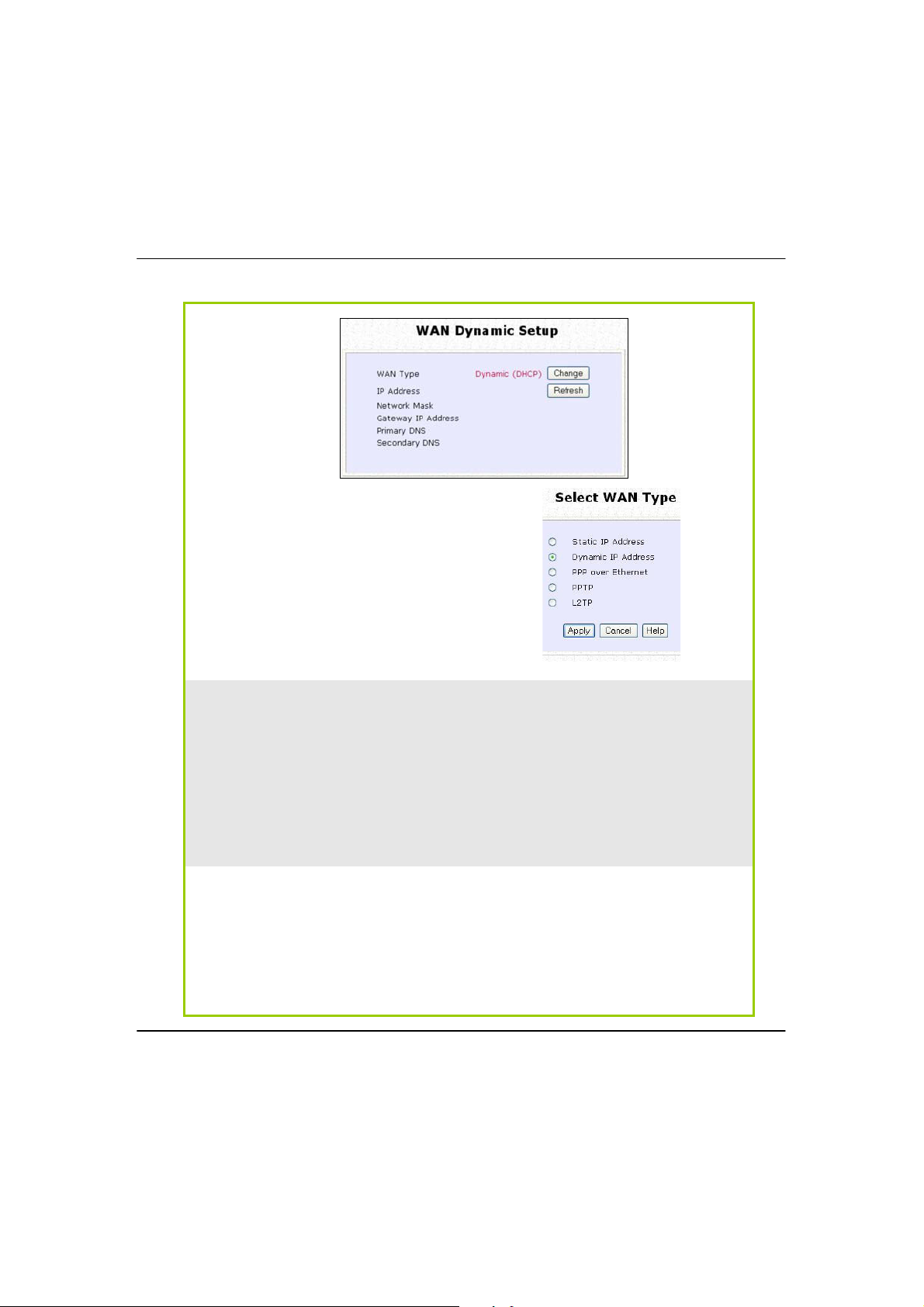
The access point is pre-configured to support a WAN type that dynamically
obtains an IP address from the ISP. However, you may verify the WAN settings with
the following steps:
Step 1: Under
CCOONNFFIIGGUURRAATTIIOON
N on the command menu, click on WWAANN
SSeettuup
p.
SStteepp22:
:
On the WWAANNDDyynnaammiiccSSeettuupp screen that follows, verify that the WWAANNTTyyppee reads
DDyynnaammiicc((DDHHCCPP)
) in red colour. Otherwise, click on the CChhaannggee button.
S
WWAANNS
(only supported by Wireless Routing Client and Gateway)
A correct WAN Setup allows you to successfully share your Internet connection
among the wired and wireless clients of the access point. To do so, you need to
identify the type of broadband Internet access you are subscribed to. If you are
using :
! Cable Internet where the ISP dynamically assigns a WAN IP address to you,
! Cable Internet where your ISP provides you with a fixed WAN IP address (or
! ADSL Internet that requires standard PPP over Ethernet (PPPoE) for
! ADSL Internet that requires standard Point-to-Point Tunneling Protocol (PPTP)
WAN Setup - Cable Internet with Dynamic IP Assignment
EETTUUP
refer to WAN Setup - Cable Internet with Dynamic IP Assignment.
a range of fixed IP addresses), refer to WAN Setup - Cable Internet with
Static IP Assignment.
authentication, refer to WAN Setup - ADSL Internet using PPP over Ethernet
(PPPoE).
for authentication, refer to WAN Setup – ADSL Internet using Point-to-Point
Tunneling Protocol (PPTP).
61
Page 73
Step 3:
Note:
Additional configuration might be required before your ISP will allocate an IP
address to the access point.
Certain ISPs require authentication through a DHCP Client ID before releasing a
public IP address to you. The access point uses the System Name in the System
Identity as the DHCP Client ID.
Therefore, if this is the case, refer to your ISP for the correct DHCP Client ID
to be set and follow steps 4 - 5 to accomplish the setup.
SStteepp44:
:
Steps 4 - 5 are for those who need to
set up the
SSyysstteemmNNaamme
e in SSyysstteemm
IIddeennttiitty
y so that your ISP can
authenticate it as a valid DHCP Client
ID.
Simply select DDyynnaammiiccIIPPAAddddrreessss
and hit the AAppppllyy button.
Please remember to click
m under SSYYSSTTEEMMTTOOOOLL
SSyysstteem
the
t button to let the settings
RReebboooot
S and hit
S
RReebboooot
t
take effect.
62
Page 74

Click on SSyysstteemmIIddeennttiittyy under the
SSYYSSTTEEMMTTOOOOLLS
S command menu.
Step 5:
On the following screen, key in the
your ISP assigned DHCP Client ID as
the
SSyysstteemmNNaamme
to key in a preferred
person and the SSyysstteemmLLooccaattiioonn of
the access point). Click the
button to complete.
e (You may also like
SSyysstteemmssCCoonnttaacct
AApppplly
y
t
Please remember to click
m under SSYYSSTTEEMMTTOOOOLLSS and hit
SSyysstteem
the
take effect.
t button to let the settings
RReebboooot
RReebboooot
t
63
Page 75

64
WAN Setup - Cable Internet with Static IP Assignment
If you have an ISP that leases a static WAN IP for your subscription, you will need
to configure your access point’s WAN type accordingly. For example, if the ISP
provided you with the following setup information, you can set up your WAN as
described below:
IP Address : 203.120.12.240
Network Mask : 255.255.255.0
Gateway IP Address : 203.120.12.2
Step 1:
Under CCOONNFFIIGGUURRAATTIIOONN on the command menu, click on WWAANNSSeettuupp.
Step 2:
Access the SSeelleeccttWWAANNTTyyppee page
and choose
SSttaattiiccIIPPAAddddrreesss
s before
clicking the
AApppplly
y button. You will
then be brought to the following
page requiring your inputs.
Step 3:
Fill in the information provided by
your ISP in the
IIPPAAddddrreessss,,NNeettwwoorrk
k
MMaassk
k andGGaatteewwaayyIIPPAAddddrreessss
fields, before clicking the AAppppllyy
button.
Please remember to click
RReebboooot
t
SSyysstteem
m under SSYYSSTTEEMMTTOOOOLLSS and hit
the
RReebboooot
t button to let the settings
take effect.
Page 76

WAN Setup - ADSL Internet using PPP over Ethernet (PPPoE)
If you subscribe to an ADSL service using PPP over Ethernet (PPPoE)
authentication, you can set up your access point’s WAN type as follows. For
example, you may configure an account whose username is ‘guest’ as
described below:
Step 1:
Under CCOONNFFIIGGUURRAATTIIOONN on the
command menu, click on
WWAANNSSeettuup
p.
Step 2:
Access the SSeelleeccttWWAANNTTyyppee page
and choose
PPPPPPoovveerrEEtthheerrnneet
t before
clicking the
AApppplly
y button. You will
then be brought to the following
page requiring your inputs.
Step 3:
ForUUsseerrnnaammee, key in your ISP
assigned account name (e.g. guest
for this example), followed by your
account
PPaasssswwoorrd
d.
Step 4:
Select AAllwwaayyss--OOnn if you want your
access point to always maintain a
connection with the ISP. Otherwise,
you may select
OOnn--DDeemmaannd
d. The
access point will then connect to the
ISP automatically when it receives
Internet requests from the PCs in your
network.
The IIddlleeTTiimmeeoouutt setting is associated with the OOnn--DDeemmaanndd option, allowing you
to specify the value (in seconds) after which the access point will disconnect
from the ISP after the last Internet activity. A value of “0” will disable idle timeout.
RReeccoonnnneeccttTTiimmeeFFaaccttoor
r is associated with the AAllwwaayy
s
s--oonn option and specifies
the maximum time the access point will wait before re-attempting to connect
with your ISP. Hit the
AApppplly
y button and RReebboooott the access point.
65
Page 77

You can limit the maximum size a packet can be in a network by setting the MMTTUU
TheMMTTUUVVaalluuee has a range of 1 to 1492.
Enter the
MMTTUUVVaalluue
e and click AAppppllyy.
(Maximum Transmissible Unit).
Click the
U Button in AAddvvaanncceeddWWAANNOOppttiioonnss.
MMTTU
66
Page 78

WAN Setup – ADSL Internet using PPTP
If you subscribe to an ADSL service using Point-to-Point Tunneling Protocol (PPTP)
authentication, you can set up your access point’s WAN type from the steps
that follow. For example, if the ISP provided you with the following set up
information, you can set up your WAN as described below:
IP Address : 203.120.12.47
Network Mask : 255.255.255.0
VPN Server : 203.120.12.15
Step 1:
Under CCOONNFFIIGGUURRAATTIIOONN on the command menu, click on WWAANNSSeettuupp.
Step 2:
Access the SSeelleeccttWWAANNTTyyppee page and
choose
PPPPTTP
P before clicking the AAppppllyy
button. You will then be brought to the
following page requiring your inputs.
Step 3:
Fill in the information provided by
your ISP in the
IIPPAAddddrreessss,
,
NNeettwwoorrkkMMaasskk,VVPPNNSSeerrvveer
r, and
DDHHCCP
P fields, followed by clicking
the
AApppplly
y button.
Please remember to click
RReeb
boooott
SSyysstteem
m under SSYYSSTTEEMMTTOOOOLLSS and
hit the
RReebboooot
t button to let the
settings take effect.
The
IIddlleeTTiimmeeoouut
t setting allows
you to specify the value (in
seconds) after which the access
point will disconnect from the ISP
after the last Internet activity. A
value of “0” will disable idle
timeout.
67
Page 79

WAN Setup – L2TP
If you’re using Layer 2 Tunneling Protocol (L2TP) authentication, you can set up
your access point’s WAN type from the steps that follow. For example, if the ISP
provided you with the following set up information, you can set up your WAN as
described below:
IP Address : 203.120.12.47
Network Mask : 255.255.255.0
VPN Server : 203.120.12.15
Step 1:
Under CCOONNFFIIGGUURRAATTIIOONN on the command menu, click on WWAANNSSeettuupp.
Step 2:
Access the SSeelleeccttWWAANNTTyyppee page and
choose
LL22TTP
P before clicking the AAppppllyy
button. You will then be brought to the
following page requiring your inputs.
Step 3:
Fill in the information provided by
your ISP in the
IIPPAAddddrreessss,
,
NNeettwwoorrkkMMaasskk,VVPPNNSSeerrvveer
r, and
DDHHCCP
P fields, followed by clicking
the
AApppplly
y button.
Please remember to click
RReeb
boooott
SSyysstteem
m under SSYYSSTTEEMMTTOOOOLLSS and
hit the
RReebboooot
t button to let the
settings take effect.
The
IIddlleeTTiimmeeoouut
t setting allows
you to specify the value (in
seconds) after which the access
point will disconnect from the ISP
after the last Internet activity. A
value of “0” will disable idle
timeout.
68
Page 80

T
Telnet allows a computer to remotely connect to the access point CLI
(Command Line Interface) for control and monitoring.
SSH (Secure Shell Host) establishes a secure host connection to the access point
CLI for control and monitoring.
Telnet/SSH Setup
Click Telnet/SSH Setup from the CONFIGURATION menu.
1. To enable Telnet Server: Select Telnet Server Enable and enter the Port Number.
2. To enable SSH server: Select SSH Server Enable and enter the Port Number.
Click
Apply.
1
2
EELLNNEET
T
T
//SSSSHHS
S
EETTUUP
P
69
Page 81

70
To add user:
1. Click Add button.
2. In Add User Entry Page, enter User Name, Password, and specify whether user is
granted permission to Read Only or Read/Write.
3. Click Apply.
To Delete User:
1. Select which user to Delete.
2. Click Delete.
3
Page 82

71
User Management list refreshes to update users.
To Refresh User Management list:
Click Refresh to refresh User Management list.
Page 83

C
The user may connect to the CLI (Command Line Interface) via a TELNET session
to the default IP, 192.168.168.1. This section uses Microsoft TELNET command for
instruction. You may use any TELNET client.
Connecting to CLI (Command Line Interface) via TELNET
1. Connect to CLI (Command Line Interface) with the following
command at DOS prompt. The TELNET application will then be launched and connect.
C:\WINDOWS\TELNET 192.168.168.1
2. At the login prompt, type in “password” (default password) and press
the <ENTER> key, as shown in Figure 2.4c. You will then login to the CLI.
TTEELLNNEETTC
Telnet CLI (Command Line Interface)
OOMMMMAANND
L
L
IINNE
I
E
NNTTEERRFFAACCE
I
E
D
72
Page 84

S
SSH is designed and created to provide the best security when
accessing another computer remotely. Not only does it encrypt the
session, it also provides better authentication facilities and features that
increase the security of other protocols. It can use different forms of
encryption and ciphers.
The first diagram below shows a telnet session.
The second diagram below shows how an encrypted connection like
SSH is not viewable on the network. The server still can read the
information, but only after negotiating the encrypted session with the
client.
EECCUURRE
S
SSH CLI (Secure Shell Host Command Line Interface)
S
H
E
L
HHEELLL
S
H
OOSST
C
T
OOMMMMAANND
C
L
L
IINNE
I
E
NNTTEERRFFAACCE
I
E
D
73
Page 85

SSH CLI has a command line interface like shown below for example.
74
Page 86

WWEEBBM
The access point supports HTTPS (SSL) in addition to the standard HTTP.
HTTPS (SSL) features additional authentication and encryption for secure
communication.
Web Management Setup
Select Web Management Setup from the CONFIGURATION menu.
1. Select whether to set web server to HTTP or HTTPS (SSL) mode.
2. Click
Apply.
Changes will be effected after reboot.
1
2
M
OODDE
E
75
Page 87

76
SSNNMMPPS
S
EETTUUP
P
Simple Network Management Protocol (SNMP) is a set of communication
protocols that separates the management architecture from the architecture
of the hardware devices.
Step 1:
Click on SSNNMMPP from the CCOONNFFIIGGUURRAATTIIOONN menu.
Step 2:
Select EEnnaabbllee from the SSNNMMPPSSttaattee drop-down list.
The default
RReeaaddPPaasssswwoorrd
d is set to public while the default RReeaadd//WWrriittee
PPaasssswwo
orrdd is private.
Step 3:
Click on the AAppppllyy button.
Page 88

P
S
SSTTPPS
(Only available in Access Point, Point to Point and Point to Multiple Point
modes)
EETTUUP
Spanning Tree Protocol (STP) is a link management
prevent undesirable loops occurs in the network. For an Ethernet network to
function properly, only one active path can exist between two stations. If a
loop exists in the network topology, duplication of messages will occur and this
might confuse the forwarding algorithm and allow duplicate frames to be
forwarded.
protocol that helps to
77
Page 89

78
In short, the main purpose of activating STP is to prevent looping when you
have redundant paths in the network. Without activating STP, redundant
topology will cause broadcast storming.
To establish path redundancy, STP creates a
tree that spans all of the devices in
an extended network, forcing redundant paths into a standby, or blocked,
state, but establishing the redundant links as a backup in case the active link
should fail. If STP costs change, or if one network segment in the STP becomes
unreachable, the spanning tree algorithm reconfigures the spanning tree
topology and re-establishes the connection by activating the standby path.
Without spanning tree in place, it is possible that more than one connection
may be simultaneously live, which could result in an endless loop of traffic on
the
LAN.
Spanning-Tree Protocol operation is transparent to end stations, which are
unaware whether they are connected to a single LAN segment or a switched
LAN of multiple segments.
Page 90

79
The path with the smallest cost will be used and extra redundant paths will be
disabled.
To explain the effect of STP & Pseudo VLAN on the wireless clients, we will
compare 3 separate scenarios.
Scenario #1
– (No STP, No Pseudo VLAN)
Referring to the illustration below, if the Spanning Tree Protocol (STP) and
Pseudo VLAN are not implemented in a network, all clients (Notebook#1, #2,
#3 & #4,) can access to one another, resulting in low level of data security. Due
to the redundant paths found in this network, broadcast packets will be
duplicated and forwarded endlessly resulting in a broadcast storm.
Page 91

80
Scenario #2 – (With STP, No Pseudo VLAN)
When STP is enabled, extra redundant network paths between APs will be
disabled, hence preventing multiple active network paths in-between any two
APs.
If one of the APs is down, the STP algorithm will reactivate one of the redundant
paths so that the network connection will not be lost.
All wireless users will be able to communicate with each other if they are
associated to the APs that are in the same WDS zone.
Page 92

81
Scenario #3 – (With STP and Pseudo VLAN)
In this example, both STP and Pseudo VLAN Per Node are implemented in this
network. When Pseudo VLAN Per Node is activated, the wireless users will be
unable to access one another.
Page 93

82
SStteepp11:
:
Click on SSTTPPSSeettuupp from the CCOONNFFIIGGUURRAATTIIOONN menu.
SStteepp22:
:
Select EEnnaabbllee from the SSTTPPSSttaattuuss radio button, fill in the fields, and click on
the
AApppplly
y button to update the changes.
Priority: (Default: 32768, Range: 0 – 65535)
This is the relative priority.
The lowest priority will be elected as the root.
Hello Time: (Default: 2, Range: 1 – 10)
This is the hello time.
Every (this number) seconds, a hello packet is sent out by.
Hello packets are used to communicate information about the topology
throughout the entire STP network.
Forward Delay: (Default: 15, Range: 4 – 30)
The forward delay is the time that is spent in the listening and learning state.
Max Age: (Default: 20, Range: 6 – 40)
The max age timer controls the maximum length of time that passes before a
port saves its configuration information.
Page 94

F
g
will not filter any MAC address
from Ethernet port.
MMAACCF
MAC Filtering acts as a security measure by controlling the users accessing to
the network through their MAC address. Each WLAN or radio card supports up
to 16 virtual access points and has its own MAC address listing. The client MAC
addresses entries can be set apply to all, or to only selected virtual access
points.
IILLTTEERRIINNG
G
NOTE: MAC Filterin
!
83
Page 95

Add a MAC address to the MAC Address List.
MAC Filtering set to EEnnaabbllee with Policy to AAcccceepptt
only the MAC addresses in the MAC Filter Address
List and deny all other MAC addresses.
MAC Filtering set to EEnnaabbllee with Policy to DDeennyy all
the MAC addresses in the MAC Filter Address List
and accept all other MAC addresses.
MAC Filtering set to DDiissaabbllee. Whether Policy is set to
EEnnaabblle
e or DDeennyy does not matter.
MAC Filtering set to DDiissaabbllee. Whether Policy is set to
EEnnaabblle
e or DDeennyy does not matter.
ClickEEddiitt.
(This displays the MAC Address List of individual virtual access points.)
SStteepp11:
SelectMMAACCFFiilltteerriinngg from WWLLAANNSSeettuupp((aa//bb//gg)).
MAC Address Filtering page displays.
:
In this page you may also set the MAC Filtering Status to
for access points and set the Policy to either AA
addresses.
EEnnaabblle
t orDDeennyy MAC
cccceeppt
e orDDiissaabbllee
84
Page 96

SStteepp22:
SStteepp33:
:
Add MAC Address page displays.
MAC Filter Address List page displays.
:
Click the
AAddd
d button.
85
Page 97

SStteepp44:
SStteepp55:
:
MAC Filter Address List page displays with updated MAC Address List.
Enter the MAC Address of the client in the format xx-xx-xx-xx-xx-xx, where x
can take any value in the range 0-9 or a-f.
Enter the Comment. This describes the MAC Address you have entered.
:
To apply to all virtual access points: Check
To apply to specific virtual access point: Select the checkbox of the corresponding
AP.
Click the
AApppplly
y button.
AAppppllyyttooAAlll
l.
86
Page 98

NOTE
Please reboot to effect all changes and new MAC address
entries.
D
D
EELLEETTEEA
A
MMAAC
C
AADDDDRREESSSSFFRROOMMAALLLLAACCCCEESSSSPPOOIINNTTS
S
.
.
SStteepp11:
:
SelectMMAACCFFiilltteerriinngg from WWLLAANNSSeettuupp((aa//bb//gg)).
MAC Address Filtering page displays.
Click
VViieewwCCoommpplleetteeMMAAC
C
LLiisstt.
.
(This displays the MAC Address List of the radio card.)
87
Page 99

SStteepp22:
SStteepp33:
:
MAC Filter Address List page displays with updated MAC Address List.
MAC Filter Address List page displays.
Select the checkbox of the MAC address you wish to delete.
:
Click the
DDeelleette
e button.
88
Page 100

D
EELLEETTEEA
D
A
MMAAC
C
AADDDDRREESSSSFFRROOMMIINNDDIIVVIIDDUUAALLAACCCCEESSSSPPOOIINNT
.
T
.
SStteepp11:
SelectMMAACCFFiilltteerriinngg from WWLLAANNSSeettuupp((aa//bb//gg)).
MAC Address Filtering page displays.
Click
:
t for the corresponding access point.
EEddiit
89
 Loading...