

Quick Install Guide
Wireless 54Mbps A+G Dualband Access Point
With Integrated PoE
NetPassage WP18 1A, 2A, 2B, 2C, 3A, 3B, 3C, 3D
NetPassage WP18 6A, 6B, 6C, 6D (RoHS-compliant)

Table of Contents
1: Introduction......................................................................................1
Packaging Content.................................................................................. 2
2: Hardwar e Setup ..............................................................................3
Option 1: Using Power Adapter to Supply Power................................ 3
Option 2: Using PoE to Supply Power..................................................... 5
3: Access to Web Interface...............................................................8
Access to the Web Interface Through Utility - uConfig ...................... 9
Access to the Web Interface Manually.............................................. 12
4: Panel Views and Descriptions.....................................................13
Panel Description....................................................................................15
5: Technical Specifications..............................................................17
WARRANTY REGISTRATION C A RD.......................................................21
i

1: Introduction
The Wireless 54Mbps A+G Dualband Access Point doesn’t just operate in wired
network environments, it also upholds simultaneous IEEE802.11a and
IEEE802.11b/g connections, as is often required in hotspots and other public
Internet access deployment.
The access point is designed to support state-of-the-art securi ty standards such
as the Wi-Fi Protected Access (WPA) protocol, the 802.1x authentication
standard, and 64/128-bits Wired Equivalent Privacy (WEP) encryption.
This high-performance access point also bears the ex clusive uConfig utility and
support broadband Internet sharing is an additional function that can be
enabled.
When the user chooses to enable routing, additional enhanced functions to the
wireless access point operation are available, such as Load Balancing; FailOver Redundancy; Parallel Broadband; built-in DHCP server; Virtual Servers
based on IP and Port Forwarding; De-Militarised Zone hosts; Packet Filtering;
and much more!
1
Packaging Content
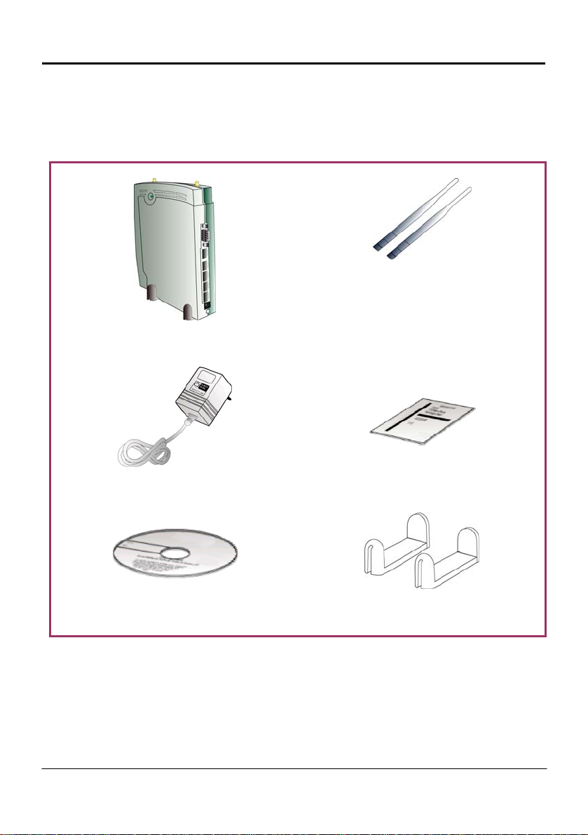
Actual product appearance may differ slightly depending on the hardware
version.
1 X Access Point
1 x Power Adapter
2 x External Antenna
1 x Read-Me-First Note
1 x Product CD
2 x Rest Foot
2
2: Hardware Setup
The access point can be powered using ei ther the power adapter, or the PoE
or IEEE 802.3af PoE.
The installation process for the three options i s described below.
Option 1: Using Power Adapter to Supply Power
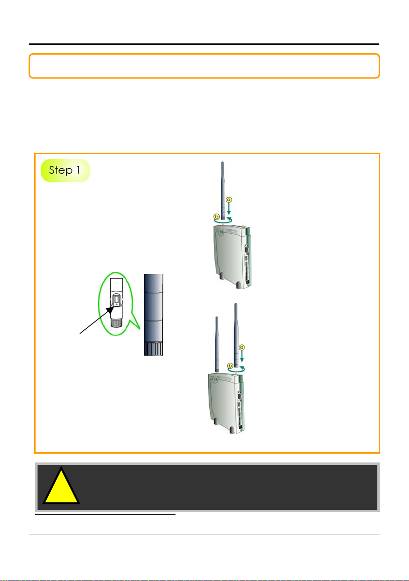
Before attaching a pair of external
antennas to the access point, take
note of the ‘A’ marking on one of
the two antennas.
The antenna with the ‘A’ marking is
the Dualband AG Antenna.
‘A’ marking
The antenna without the marking is
the single-band G Antenna.
!
Important: To ensure proper functionality of the
access point, these two antennas MUST
NOT be swapped.
• PoE is available in several mo dels and powe r outputs.
Please contact your supplier for the correct model and power requirements.
3
Connect the single-band
G antenna to Ant-2 on
the RIGHT.
Connect the Dualband
AG antenna to Ant-1 on
the LEFT.
*
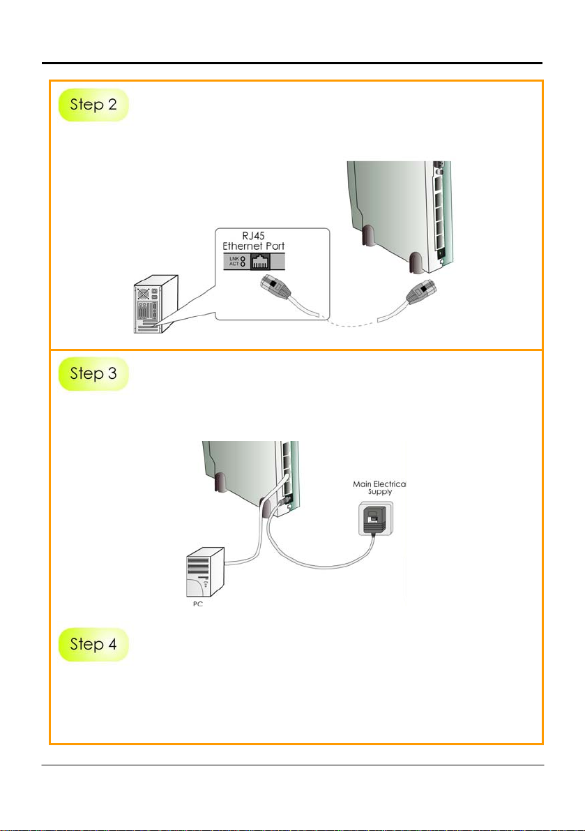
Insert one end of the RJ45 Ethernet cable to any of the LAN ports (1, 2, 3, or 4)
on the access point and the other end to your PC’s Ethernet network adapter.
PC
Attach the power adapter to the main electrical supply and connect the
power plug into the socket of the access point.
Power on your PC.
Notice that the Power and the corresponding port LEDs have lighted up.
This indicates that connection has b een established successfully between the
access point and your PC.
4
Option 2: Using PoE to Supply Power
PoE (Power-Over-Ethernet) can be used to power the access point. This
accessory supplies operational power to the wireless access poi nt through the
Ethernet cable connection and is available separately.
If you wish to use PoE to supply power to the access point, follow the steps
below:
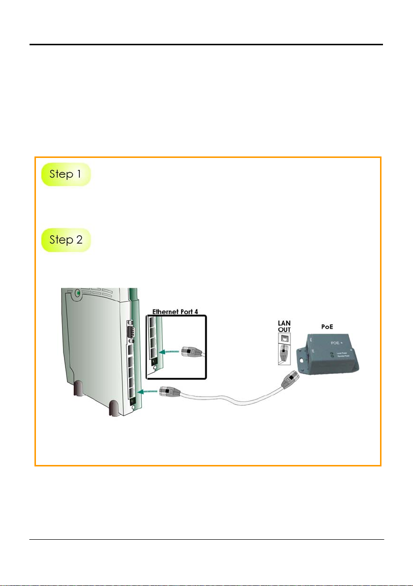
Follow the steps described in Option One.
Connect one end of an RJ45 Ethernet cable to LAN OUT port of the PoE
Injector and the other end to Port 4 of the access point.
For PoE, the recommended length of the RJ45 Category 5 cable is up to 50
metres.
5

Connect the RJ45 Ethernet cable attached to the PoE Inj ector to your PC’s
Ethernet network adapter.
Once you have finished configuri ng the access point, you can connect the
PoE Injector’s RJ45 Ethernet cable to your network device, such as a switch or
a hub.
Connect the power adapter supplied in the PoE kit to the main electrical
supply and the power plug into the socket of the injector.
Note:
DO NOT interchange the access point and PoE power adapters.
The voltage and current supply is incompatible.
6
 Loading...