

Page 1
Quick Install Guide
Wireless 54Mbps A+G Dualband Access Point
With Integrated PoE
NetPassage WP18 1A, 2A, 2B, 2C, 3A, 3B, 3C, 3D
NetPassage WP18 6A, 6B, 6C, 6D (RoHS-compliant)
Page 2

Table of Contents
1: Introduction......................................................................................1
Packaging Content.................................................................................. 2
2: Hardwar e Setup ..............................................................................3
Option 1: Using Power Adapter to Supply Power................................ 3
Option 2: Using PoE to Supply Power..................................................... 5
3: Access to Web Interface...............................................................8
Access to the Web Interface Through Utility - uConfig ...................... 9
Access to the Web Interface Manually.............................................. 12
4: Panel Views and Descriptions.....................................................13
Panel Description....................................................................................15
5: Technical Specifications..............................................................17
WARRANTY REGISTRATION C A RD.......................................................21
i
Page 3

1: Introduction
The Wireless 54Mbps A+G Dualband Access Point doesn’t just operate in wired
network environments, it also upholds simultaneous IEEE802.11a and
IEEE802.11b/g connections, as is often required in hotspots and other public
Internet access deployment.
The access point is designed to support state-of-the-art securi ty standards such
as the Wi-Fi Protected Access (WPA) protocol, the 802.1x authentication
standard, and 64/128-bits Wired Equivalent Privacy (WEP) encryption.
This high-performance access point also bears the ex clusive uConfig utility and
support broadband Internet sharing is an additional function that can be
enabled.
When the user chooses to enable routing, additional enhanced functions to the
wireless access point operation are available, such as Load Balancing; FailOver Redundancy; Parallel Broadband; built-in DHCP server; Virtual Servers
based on IP and Port Forwarding; De-Militarised Zone hosts; Packet Filtering;
and much more!
1
Page 4
Packaging Content
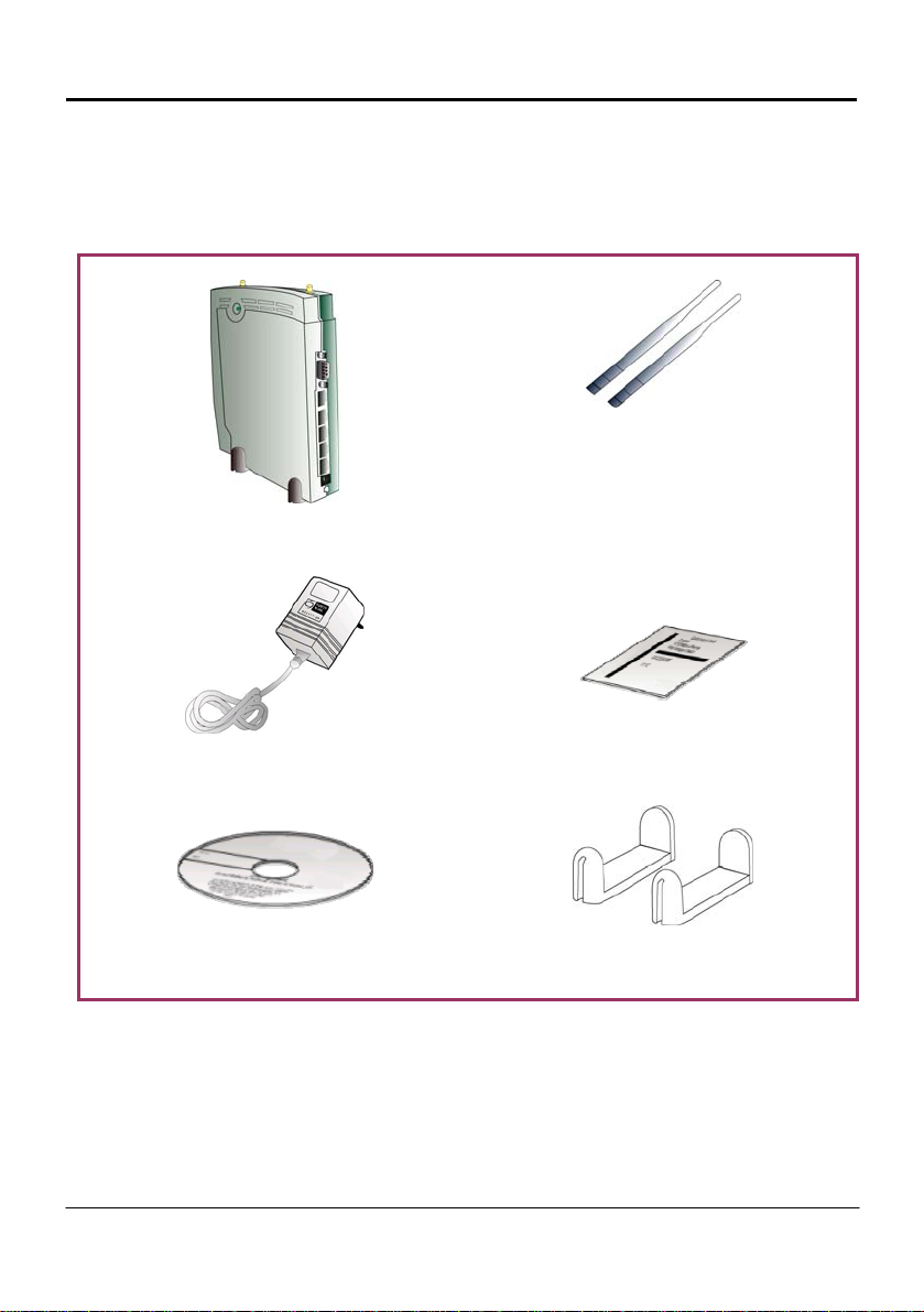
Actual product appearance may differ slightly depending on the hardware
version.
1 X Access Point
1 x Power Adapter
2 x External Antenna
1 x Read-Me-First Note
1 x Product CD
2 x Rest Foot
2
Page 5
2: Hardware Setup
The access point can be powered using ei ther the power adapter, or the PoE
or IEEE 802.3af PoE.
The installation process for the three options i s described below.
Option 1: Using Power Adapter to Supply Power
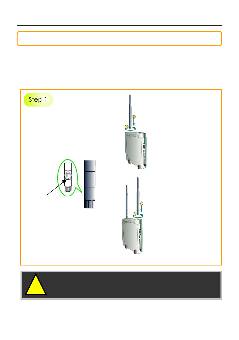
Before attaching a pair of external
antennas to the access point, take
note of the ‘A’ marking on one of
the two antennas.
The antenna with the ‘A’ marking is
the Dualband AG Antenna.
‘A’ marking
The antenna without the marking is
the single-band G Antenna.
!
Important: To ensure proper functionality of the
access point, these two antennas MUST
NOT be swapped.
• PoE is available in several mo dels and powe r outputs.
Please contact your supplier for the correct model and power requirements.
3
Connect the single-band
G antenna to Ant-2 on
the RIGHT.
Connect the Dualband
AG antenna to Ant-1 on
the LEFT.
*
Page 6
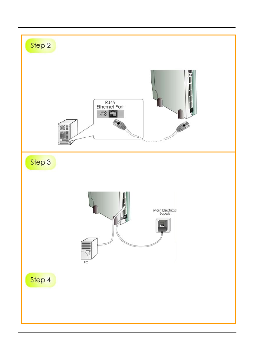
Insert one end of the RJ45 Ethernet cable to any of the LAN ports (1, 2, 3, or 4)
on the access point and the other end to your PC’s Ethernet network adapter.
PC
Attach the power adapter to the main electrical supply and connect the
power plug into the socket of the access point.
Power on your PC.
Notice that the Power and the corresponding port LEDs have lighted up.
This indicates that connection has b een established successfully between the
access point and your PC.
4
Page 7
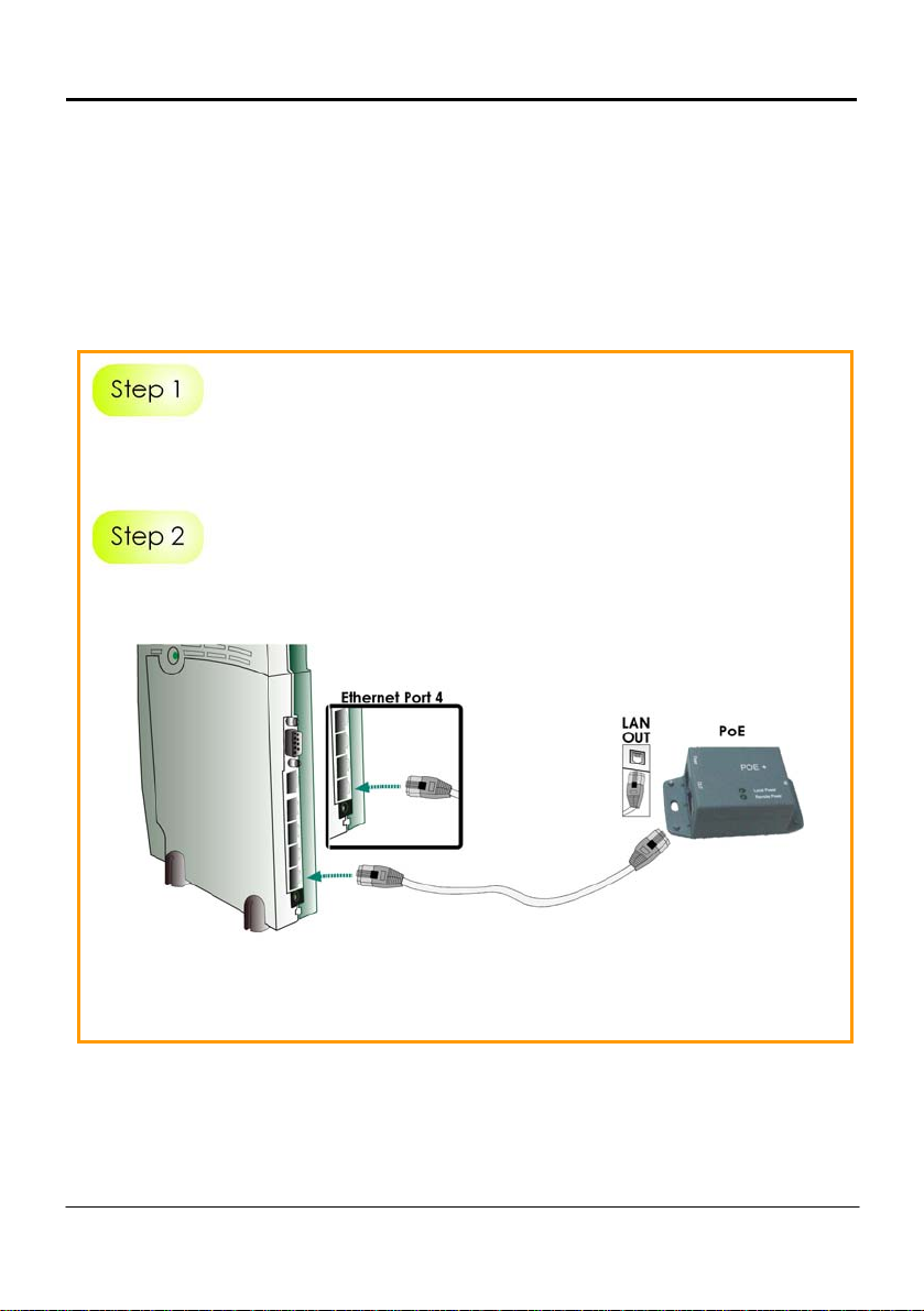
Option 2: Using PoE to Supply Power
PoE (Power-Over-Ethernet) can be used to power the access point. This
accessory supplies operational power to the wireless access poi nt through the
Ethernet cable connection and is available separately.
If you wish to use PoE to supply power to the access point, follow the steps
below:
Follow the steps described in Option One.
Connect one end of an RJ45 Ethernet cable to LAN OUT port of the PoE
Injector and the other end to Port 4 of the access point.
For PoE, the recommended length of the RJ45 Category 5 cable is up to 50
metres.
5
Page 8

Connect the RJ45 Ethernet cable attached to the PoE Inj ector to your PC’s
Ethernet network adapter.
Once you have finished configuri ng the access point, you can connect the
PoE Injector’s RJ45 Ethernet cable to your network device, such as a switch or
a hub.
Connect the power adapter supplied in the PoE kit to the main electrical
supply and the power plug into the socket of the injector.
Note:
DO NOT interchange the access point and PoE power adapters.
The voltage and current supply is incompatible.
6
Page 9

Turn on your power supply. Notice that the Power LEDs have lighted up . This
indicates that the access poi nt is receiving power through th e PoE Injector.
Notice also that the Port 4 LEDs have lighted up. This indicates that
connection between the access point and your PC has been established.
7
Page 10

3: Access to Web Interface
There are 2 methods to access the web interface of the access point:
1. Access to the Web Interface Through Utility – uConfig
Access the web interface direc tly without hav ing to change the I P address
of your PC.
2. Access to the Web Interface Through web browser
1. Assign an IP address to your PC so that it is in the same subnet
as the access point.
(Example: 192.168.168.xxx where x can be any value from 2 to
254)
2. Enter IP address of the access point in the address bar of
Internet Explorer and press Enter.
8
Page 11
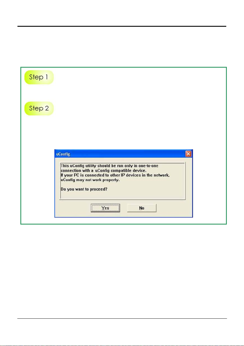
Access to the Web Interface Through Utility - uConfig
The powerful uConfig utility provides convenient access to the web
configuration page.
Insert the Product CD into your CD-ROM drive.
From the Utilities section, select to install the uConfig utility to your hard disk.
After installation, double-click on the uConfig icon.
The following screen will appear, click on the Yes button to proceed.
9
Page 12
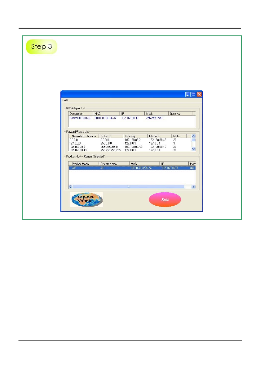
Select the access point in the products list section and click on Open Web
button.
To update and displa y the available device(s) i n the list, click on the Refresh
button.
10
Page 13
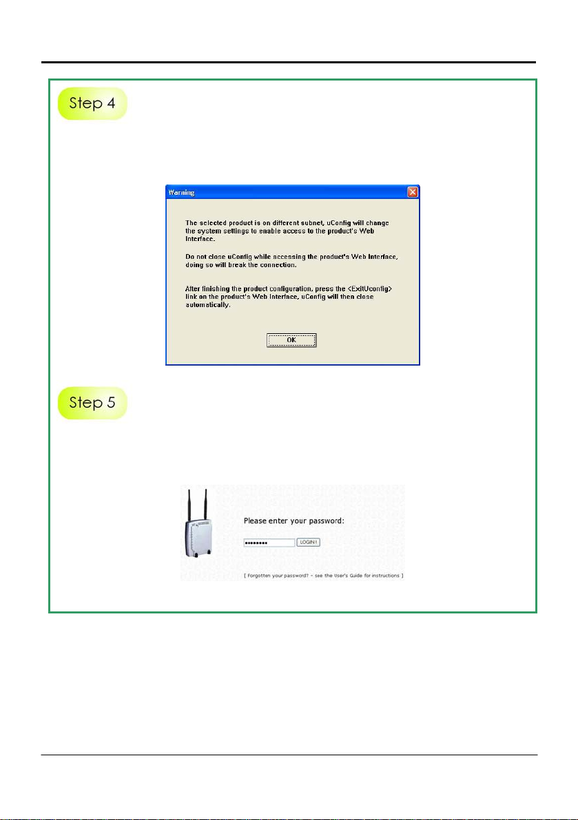
This screen prompts you not to exit your uConfig program while accessing to
your web interface, or else you will fail to connect to your device.
Click on the OK button to proceed.
At the authentication page, click on the LOGIN! button to enter the main
configuration page.
The default password is “password”.
11
Page 14
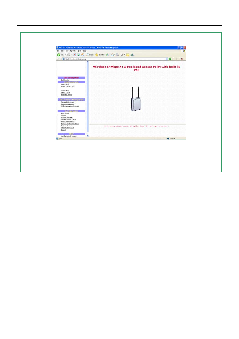
You will then reach the home page of the access point web interface.
Note:
Refer to User’s Manual for detailed instructions on configuring the access point
for wireless access.
Access to the Web Interface Manually
To access the web interface manually, you need to configure the TCP/IP of
your PC.
Refer to User’s Manual Chapter 4: Accessing the Web Interface for details.
12
Page 15
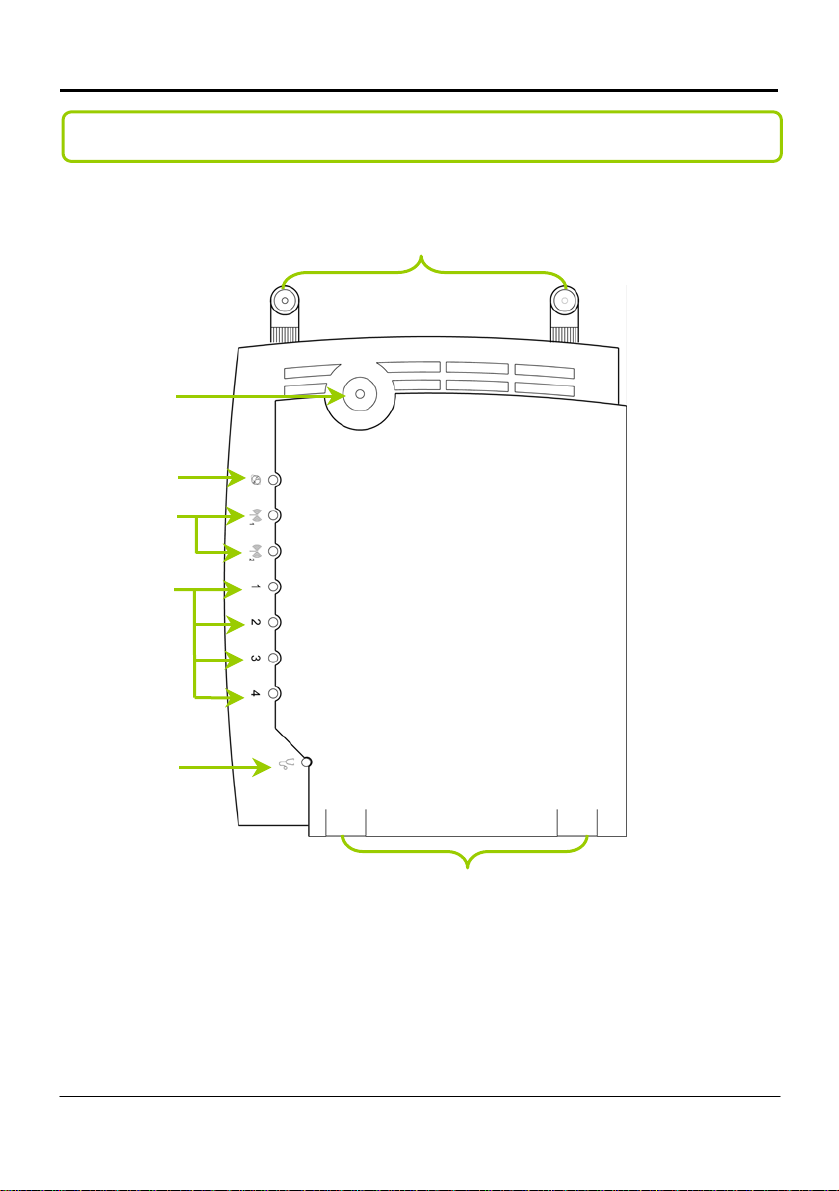
4: Panel Views and Descriptions
Front View in standing position
1
2
3
4
7
5
Rest feet attached to the botto m of
the access point
6
13
Page 16
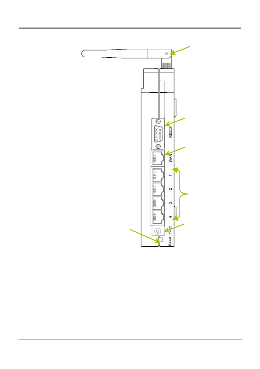
Side View in standing position
7
8
9
10
12
11
14
Page 17
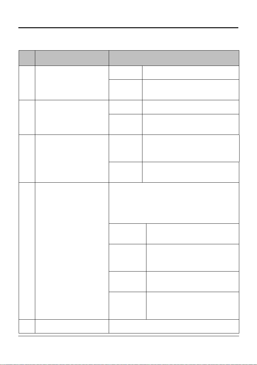
Panel Description
Name Description
1 Power (LED)
2 WAN (Link/Activi ty LED)
3 WLAN (1), (2)
(Link/Activi ty LED)
4 1, 2, 3, 4
(Link/Activity/Speed
LEDs)
5 DIAG (LED) This LED is reserved for diagnostic purposes.
Steady
Green
Off No power is supplied to the
Steady
Green
Flashing
Green
Steady
Green
Flashing
Green
These LEDs reflect the status of the integrated
Fast Ethernet Switch.
They will light up when connected with an
Ethernet cable.
Steady
Green
Flashing
Green
Steady
Amber
Flashing
Amber
15
The device is powered up.
device.
The WAN connection is ON.
Data transmission at WAN
connection.
Wireless interface up and
running.
Ready for operation.
Activity is detected in the wireless
network.
There is a connectivity link of
100Mbps.
100Mbps data transmission is
detected at the port
concerned.
There is a connectivity link of
10Mbps.
10Mbps data transmission is
detected at the port
concerned.
Page 18
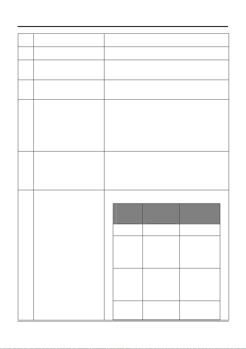
6 Rest Feet These rest feet hold the access point in the
standing position.
7 External Antennas SMA antennas
8 R232 (Integrated Serial
Interface)
Not in use.
Reserved for future update.
9 WAN (Ethernet Port)
10/100Base-T Port connects to Cable/ADSL
modem.
10 1, 2, 3, 4 (Ethernet Ports) Integrated 3-port 10/100Mbps Switching.
Ports 1, 2, 3, and 4 all function as normal
Ethernet ports except that Port 4 supports PoE
connection.
Connect Port 4 to PoE Injector if you wish to
use it to supply power to the unit.
11 DC Jack Direct Current jack.
If using power adapter to supply power to the
unit, attach the power adapter to the main
electrical supply and connect the power plug
into the DC Jack of the access point.
12 Reset (Push Button)
The table below illustrates the use of the Reset
button.
Reset
Push
Button
Less than
3 sec
5 sec Fast Blinking Restores the
Between
8 sec and
10 sec
More
than 10
sec
Diagnostic
LED
Access Point
Behavior
On Reboots.
Slow Blinking Restores all the
Off Reset
default login
password,
which is
‘password’.
default factory
settings
including
password.
cancelled.
16
Page 19
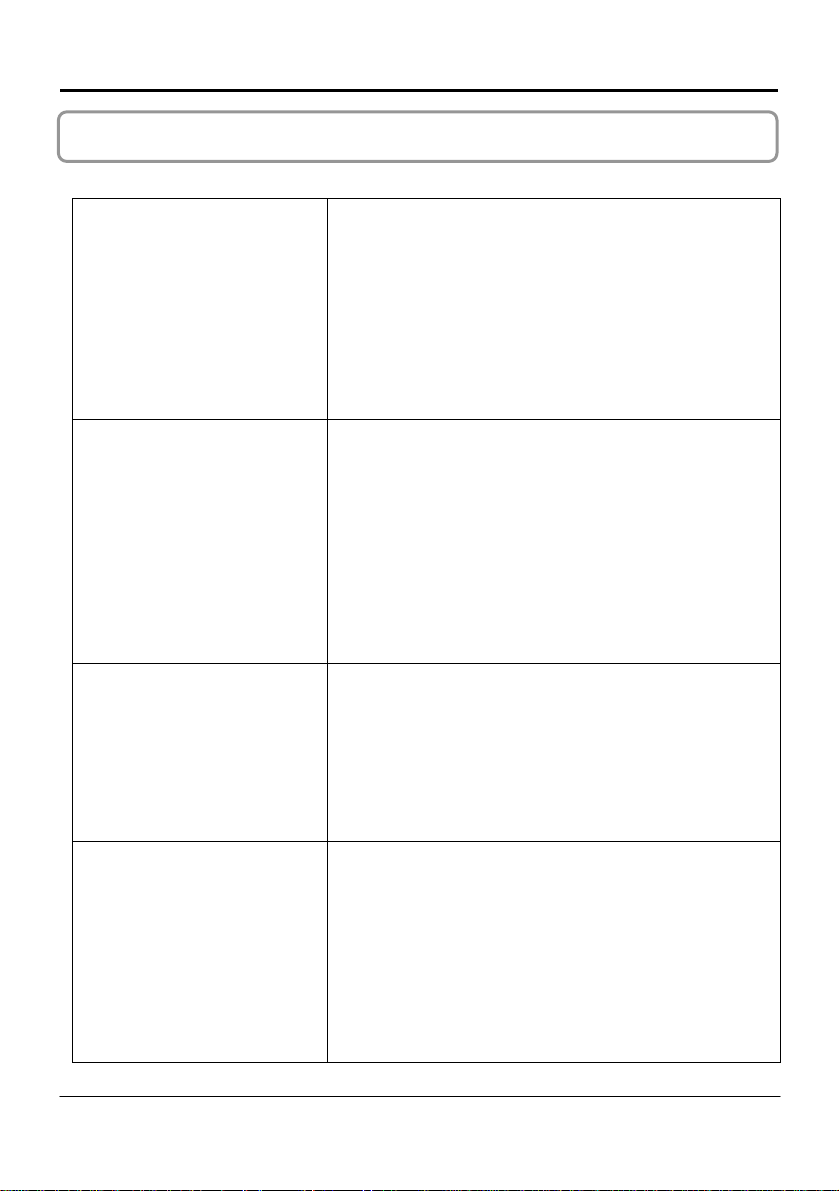
5: Technical Specifications
Safety and
Electromagnetic
Conformance
Standards • IEEE 802.11a
Wireless Operating Range • IEEE 802.11a
Frequency Range
IEEE 802.11a:
IEEE 802.11b:
IEEE 802.11g:
(Frequency range for the
respective countries can
be selected from the
world regulatory domain
selection in device setup.)
• FCC Part 15 SubPart B and SubPart C [for
wireless module]
• EN 300 328-2 [for wireless module]
• EMC CE EN 301 489 (EN300 826) [for wireless
module]
• EN 55022 (CISPR 22)/EN 55024 Class B
• EN 61000-3-2
• EN61000-3-3
• CE EN 60950
54Mbps, 48Mbps, 36Mbps, 24Mbps, 18Mbps,
12Mbps, 9Mbps, 6Mbps, 1Mbps
• IEEE 802.11b
11Mbps, 5.5Mbps, 2Mbps, 1Mbps
• IEEE 802.11g
54Mbps, 48Mbps, 36Mbps, 24Mbps, 18Mbps,
12Mbps, 9Mbps, 6Mbps, 1Mbps
85m (54Mbps outdoor), 20m (54Mbps indoor)
• IEEE 802.11b
300m (11Mbps outdoor), 100m (11Mbps indoor)
• IEEE 802.11g
80m (54Mbps outdoor), 20m (54Mbps indoor)
5.180 ~ 5.825 GHz (For all countries)
2.4 ~ 2.4835 GHz
2.4 ~ 2.497 GHz
17
Page 20

Network Interface
WAN Interface:
1 x 10/100 Mbps
LAN Interface:
3 x 10/100 Mbps
Power over Ethernet:
1 x PoE
Security • 64 - bit / 128 – bit WEP
• WPA Personal
• WPA Enterprise
• WPA2-Personal
• WPA2-Enterprise
• WPA-Auto-Personal
• WPA-Auto-Enterprise
• Wireless Pseudo Virtual LAN
• IEEE 802.1x – TLS, TTLS, PEAP, EAP-SIM
• Stateful Packet Inspection Firewall
Output Power
IEEE 802.11a:
IEEE 802.11b:
IEEE 802.11g:
18 dBm
20 dBm
20 dBm
Management SNMP, Web browser, uConfig
Advanced Features
• Long Distance Parameters Setup
• Dynamic DNS Service (Subscribe service)
• STP
• HTTPS
Resiliency Parallel Broadband
Profile Backup & Restore Yes
Firmware Upgrade Yes
Power Requirements
Using Power Adapter:
Using PoE:
• Output 9VDC (localized to country of sale)
• PoE Injector or IEEE 802.3af Injector
18
Page 21

Certifications • FCC
• CE Mark
• Gost
• C-tick N 12030
Environment Requirements
Operating Temp:
Storage Temp:
Operating Humidity:
Antenna Configuration
(WP18 1A)
ANT-1:
ANT-2:
Antenna Configuration
(WP18 2A, 2B, 2C, 3A, 3C,
3D)
ANT-1:
ANT-2:
0ºC to 55ºC
-20ºC to 75ºC
10% to 80% RH
Humidity (RH – Relative Humidity):
WLM54AG (a/b/g) card MAIN
WLM54AG (a/b/g) card AUX
WLM54AG (a/b/g) card MAIN
WLM54G (b/g) card MAIN
Further Information References
For more details on the access point configuration, please refer to the User’s
Manual in the accompanying Product CD.
This document may become superseded, in which case you may fi nd its latest
version at:
http://www.compex.com.sg
19
Page 22

Disclaimer: Compex, Inc. provides this guide without warranty of any kind, expressed or implied, including but not
limited to the implied warranties of merchantability and fitness for a particular purpose. Compex, Inc. may make
improvements and/or changes to the product and/or specifications of th e produc t descri b e d in this guide, without prior
notice. Compex, Inc will not be liable for any technical inaccuracies or typographical errors found in this guide.
Changes are periodically made to the information contained herein and will be incorporated into later versions of the
guide. The information contained is subject to change witho ut prior notice.
Trademark Information: Compex®, ReadyLINK® and MicroHub® are registered trademarks of Compex, Inc. Microsoft
Windows and the Windows logo are the trademarks of Microsoft Corp. NetWare is the registered trademark of Novell Inc.
All other brand and product names are trademarks or registered trademarks of their respective owners.
Notice: Copyrights © 2006 by Compex, Inc. All rights reserved. Reproduction, adap tation, or translation without prior
permission of Compex, Inc. is prohibited, except as allowed under the copyright laws.
Manual Revision by Daniel
Manual Number: M-0508-V1.3C Version 1.3, December 2006
FCC NOTICE: This device has been tested and found to comply with the limits for a Class B digital device, pursuant to
Part 15 of the FCC Rules. These limits are designed to provide reasonable protection against harmful interference in a
residential installation. This device generates, uses and can radiate radio frequency energy and, if not installed and
used in accordance with the instructions, may cause harmful interference to radio communications. However, there is
no guarantee that interference will not occur in a particular installation. If this device does cause harmful interference to
radio or television reception, the user is encouraged to try to correct the interference by one or more of the following
measures:
Reorient or relocate the receiving antenna.
Connect the computer into an outlet on a
circuit different from that to which the receiver is
connected.
Caution: Any changes or modifications not expressly approved by the grantee of this device could void the user's
authority to operate the equipment.
FCC Compliance Statement: This device complies with Part 15 of the FCC Rules. Operation is subject to the following two
conditions:
(1)
This device may not cause harmful interference, and
(2)
This device must accept any interference received, including interference that may cause undesired
operation.
Products that contain a radio transmitter are labeled with FCC ID and may also carry the FCC logo.
Caution: Exposure to Radio Frequency Radiation.
To comply with the FCC RF exposure compliance requirements, the following antenna installation and device operating
configurations must be satisfied:
a.
For configurations using the integral antenna, the separation distance between the antenna(s) and any person’s
body (including hands, wrists, feet and ankles) must be at least 2.5cm (1 inch).
b.
For configurations using an approved external antenna, the separation distance between the antenna and any
person’s body (including hands, wrists, feet and ankles) must be at least 20cm (8 inch).
The transmitter shall not be collocated with other transmitters or antennas.
ICES 003 Statement
This Class B digital apparatus complies with Canadian ICES-003.
DECLARATION OF CONFORMITY: Compex, Inc. declares that the product:
Product Name: Compex Wireless 54Mbps A+G Access Point with integrated PoE
Model No.: NetPass age WP18 conforms to the following Product Standards:
This device complies with the Electromagnetic Compatibility Directive (89/336/EEC) issued by the Commission of the
European Community. Compliance with this directive implies conformity to the following European Norms (in brackets
are the equivalent international standards.)
Electromagnetic Interference (Conduction and Radiation): EN 55022 (CISPR 22)
Electromagnetic Immunity
Low Voltage Directive:
Therefore, this product is in conformity with the following regional standards: FCC Class B: following the provisions of FCC
Part 15 directive; CE Mark: following the provisions of the EC directive.
DECLARATION OF CONFORMITY: Compex, Inc. declares that:
The wireless card in this product complies with the R&TTE Directive (1999/5/EC) issued by the Commission of the
Europe an Community. Compliance with this dir ective implies conformity to the following:
EMC Standards: FCC: 47 CFR Part 15, Subpart B, 47 CFR Part 15, Subpart C (Secti on 15.247 ); CE: EN 300 328-2, EN 300 826
(EN 301 489-17)
Therefore, this product is in conformity with the following regional standards: FCC Class B: following the provisions of FCC
Part 15 directive; CE Mark: following the provisions of the EC directive.
Manufacturer’s Name: Compex Systems Pte Ltd
Address: 135 Joo Seng Road, PM Industrial Buil ding, #08-01, Singapore 368363
: EN 55024 (IEC61000-4-2,3,4,5,6,8,11)
EN 60 950: 1992+A1: 1993+A2: 1993+A3: 1995+A4: 1996+A11:1997.
Increase the separation between the computer and
receiver.
Consult the dealer or an experienced radio / TV
technician for help.
20
Page 23
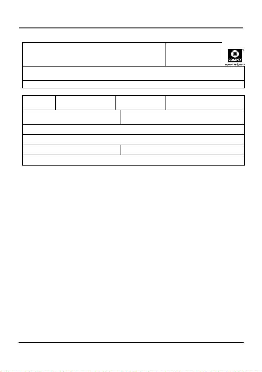
WARRANTY REGISTRATION CARD
Register via the Internet a t http://www.cpx.com
or http://www.compex.com.sg
To activate the warranty, please complete this card and return to Compex
within ninety (90) days from the date of purchase.
Please e-mail this warranty card to [email protected].
Product: Purchase Date: Model: Serial No:
Name: E-mail:
Company:
Address:
Postal/Zip Code: Country:
Phone: ( )
Note:
For purchases within U.S.A and Canada, please fax to Compex, Inc. at
(714) 482 0332
For purchases outside U.S.A and Canada, please fax to Com pex Systems Pte
Ltd at (65) 6280-9947
[M-0088-V2.4C]
21
Page 24

Manual Number:
M-0508-V1.3C
Version 1.3
December 2006
 Loading...