

Page 1
WLU108AG-MC
User manual
Page 2

© Copyright 2007 Compex Systems Pte Ltd
All Rights Reserved
This document contains information, which is protected by copyright.
Reproduction, adaptation or translation without prior permission is prohibited,
except as allowed under the copyright laws.
Trademark Information
Compex® is a registered trademark of Compex, Inc. Microsoft Windows and the
Windows logo are the trademarks of Microsoft Corp. NetWare is the registered
trademark of Novell Inc. All other brand and product names are trademarks or
registered trademarks of their respective owners.
Notice: Copyrights © 2007 by Compex, Inc. All rights reserved. Reproduction,
adaptation, or translation without prior permission of Compex, Inc. is prohibited,
except as allowed under the copyright laws.
Manual Revision by Daniel
Manual Number: U-0550-V1.4C, Version 1.4, May 2007
Disclaimer
Compex, Inc. provides this manual without warranty of any kind, either
expressed or implied, including but not limited to the implied warranties of
merchantability and fitness for a particul ar purpose. Compex, Inc. may make
improvements and/or changes to the product and/or specifications of the
product described in this manual, without pri or notice. Compex, Inc will not be
liable for any technical inaccuracies or typographical errors found in thi s guide.
Changes are periodically made to the information contained herein and will
be incorporated into later versions of the manual. The i nformation contained is
subject to change without prior notice.
Your Feedback
We value your feedback. If you find any errors in this user’s manual, or if you
have suggestions on improving, we would like to hear from you. Please contact
us at:
Fax: (65) 62809947
Email: feedback@compex.com.sg
i
Page 3

FCC NOTICE
This device has been tested and found to comply with the limits for a Class B
digital device, pursuant to Part 15 of the FCC Rules. These limits are designed to
provide reasonable protection against harmful interference in a residential
installation. This device generates, uses and can radiate radio frequency
energy and, if not installed and used in accordance with the instructions, may
cause harmful interference to radio communications. However, there is no
guarantee that interference will not occur in a particular installation. If this
device does cause harmful interference to radio or television reception, the
user is encouraged to try to correct the interference by one or more of the
following measures:
• Reorient or relocate the receiving antenna.
• Connect the computer into an outlet on a circuit different from that to
which the receiver is connected.
• Increase the separation between the computer and receiver.
• Consult the dealer or an experienced radio/TV technici an for help.
Caution: Any changes or modifications not expressly approved by the gran tee
of this device could void the user's authority to operate the equipment.
FCC Compliance Statement: This device complies with Part 15 of the FCC Rules.
Operation is subject to the following two conditio ns:
1. This device may not cause harmful i nterference, and
2. This device must accept any interference received, including interference
that may cause undesired operation.
This device must accept any interference received, including interference that
may cause undesired operation.
Caution: Exposure to Radio Frequency Radiation.
RF exposure warning: The equipment complies with FCC RF exposure limits set
forth for an uncontrolled environment. The equipment must not be co-located
or operating in conjunction with any other antenna or transmi tter.
Max. SAR Measurement (1g)
802.11b: 0.542 W/kg
802.11g: 0.540 W/kg
802.11a (5.2GHz): 1.205 W/kg
802.11a (5.8GHz): 1.314 W/kg
ii
Page 4

Outdoor operations in the 5.15-5.25GHz band is prohibited.
This device has no Ad-hoc capability or peer-to-peer operations for 5250~5350
and 5470~5725 MHz.
IEEE 802.11b or 802.11g operation of this product in the U.S.A. i s firmware-limi ted
to channels 1 through 11.
IMPORTANT NOTE: In the event that these conditions can not be met (for
example certain laptop configurations or co-l ocation with another transmi tter),
then the FCC authorization is no longer considered valid and the FCC ID can
not be used on the final product. In these circumstances, th e OEM integrator
will be responsible for re-evaluati ng the end product (including the tra nsmitter)
and obtaining a separate FCC authorization.
Note: This device has the same WLAN behavior with all other WLAN devices
because we design this device to be compliant to 802.11 specifications.
The fundamental access method of the IEEE802.11 MAC is CSMA/CA, that
means when one station desiring to transmit sense the medium, if the medium is
busy(i.e. some other station is transmitting) then the station will defer its
transmission to a later time. I f the medium is sensed free then the station is
allowed to transmit. The receiving station will check the CRC of the received
packet and send an acknowledgement packet(ACK). Receipt of the ACK will
indicate that no collisi on occurred. If the sender does not receive the ACK then
it will retransmit the fragment until it gets acknowledged or thrown away after
a given number of retransmissions
When WLAN device is in idle status, it is listening (RX), and it won’t send any
packets.
In fault condition, or WLAN device is out of control, WLAN device self can not
generate any packets, even beacon frames , so that WLAN device won’t send
out unexpected frames to air and break FCC rules.
DECLARATION OF CONFORMITY
Compex, Inc. declares that the product:
Product Name: Compex Wireless 108Mbps USB 2.0 Adapter
Model No.: WLU108 conforms to the following Product Standards:
This device complies with the Electromagnetic Compatibility Directive
(89/336/EEC) issued by the Commission of the European Community.
iii
Page 5

Compliance with this directive implies conformity to the following European
Norms (in brackets are the equivalent international standards.)
Electromagnetic Interference (Conduction and Radiation):
EN 55022 (CISPR 22)
EMC Standards:
FCC Part 15: Subpart B, Subpart C, Subpart E;
Low Voltage Directive:
EN 60 950-1: 2001.
Therefore, this product is in conformity with the following regional standards:
FCC Class B - following the provisions of FCC Part 15 directive;
iv
Page 6
Technical Support Information
The warranty information and registration form are found in the Quick Install
Guide.
For technical support, you may contact Compex or its subsidiaries. For your
convenience, you may also seek technical assi stance from the local di stributor,
or from the authorized dealer/reseller that you have purchased this product
from. For technical support by email, write to support@compex.com.sg.
Refer to the table below for the nearest Technical Support Centers:
Technical Support Centers
Contact the technical support center that services your location.
U.S.A., Canada, Latin America and South America
Write
Call
Fax
Write
Call
Fax
Internet
access/
Website:
Compex, Inc.
840 Columbia Street, Suite B,
Brea, CA92821, USA
Tel:
+1 (714) 482-0333 (8 a.m.-5 p.m. Pacific time)
Tel:
+1 (800) 279-8891 (Ext.122 Technical Support)
Fax:
+1 (714) 482-0332
Asia, Australia, New Zealand, Middle East and the rest of the World
Compex Systems Pte Ltd
135, Joo Seng Road #08-01, PM Industrial Building
Singapore 368363
Tel:
(65) 6286-1805 (8 a.m.-5 p.m. local time)
Tel:
(65) 6286-2086 (Ext.199 Technical Support)
Fax:
(65) 6283-8337
E-mail:
FTPsite:
http://www.cpx.com or http://www.compex.com.sg
support@compex.com.sg
ftp.compex.com.sg
v
Page 7

Table of Contents
About This Document
The product described in this document, Compex Wireless 108Mbps USB 2.0
Adapter, Compex WLU108 is a licensed product of Compex Systems Pte Ltd.
This document contains instructions for installing, configuring and using Compex
WLU108. It also gives an overvi ew of the key applications and the networking
concepts with respect to the product.
This documentation is for both Network Administrators and the end user who
possesses some basic knowledge in the networking structure and protocols.
It makes a few assumptions that the host compu ter has already been installed
with TCP/IP and already up & running and accessing the Internet. Procedures
for Windows 2000/XP operating systems are included in this document.
How to Use this Document
This document may become superseded, in which case you may fi nd its latest
version at http://www.compex.com.sg
The document is written in such a way that you as a u ser will find it convenient
to find specific information pertaini ng to the product. It comprises of chapters
that explain in detail the installation and configuration of Compex WLU108.
Drivers & Utilities
This manual is written based on Drivers v ersion 1.5.0.102; Utility version 40.1.2.75
vi
Page 8

Table of Contents
Conventions
In this document, special conventions are used to help and present the
information clearly. The Compex Wireless 108Mbps USB 2.0 Adapter is often
referred to as Compex WLU108 in this document. Belo w is a list of conventions
used throughout.
NOTE
This section will consist of important features or instructions
References on Menu Command, Push Button, Radio Button, LED and Label
appear in Bold. For example, “Click on Ok.”
vii
Page 9

Chapter 1 Product Overview
Chapter 1 Product Overview
1.1 Introduction
The Wireless 108Mbps USB 2.0 Adapter delivers the performance and
capabilities that every mobile user is looking for. Embedded with Atheros
chipset, it boasts network robustness, stability and wider coverage for longrange connectivity. Despite its small size, the USB adapter is big on features;
compatibility with wireless 802.11 networks ensures tha t you can be connected
easily.
Bandwidth needs in the home are increasing rapidly with the introduction of
new devices and services. As broadband infrastructure becomes common in
homes, the demand for multimedia services such as video streaming or VoIP
also increases.
Connecting to a wireless LAN without adequate security measures generally
opens up your shared folders to any casual snoopers. To protect your pri vacy,
the USB adapter is armed with many enhanced wireless security features such
as WPA, IEEE 802.1x Authenticati on and 64/128/152-bit WEP (Wired Equivalent
Privacy) to ensure privacy for the heterogeneous mix of users withi n the same
wireless LAN while maintaining full access to the establishment’s resources.
1
Page 10

Chapter 1 Product Overview
1.2 Features and Benefits
• Compact and Mobile
The USB adapter is designed especially for the mobile generation.
The casing is compact and sleek, and the antenna is built-in to
further preserve the miniature footprint. Weighing just 20 gram s, the
device is light enough to be carried around!
• Fast and Reliable Transmission
The USB adapter can deliver up to 108Mbps wireless throughput. At
the same time, the USB adapter provides reliable wireless
transmission to all wireless users with its auto rate fallback capability.
• USB powered and USB 2.0 fast transfer rate
Leveraging on the USB standard, the USB adapter is powered
through its USB connection and requires no additional power
adapter. USB 2.0 standard allows a significant improvement in
transfer rate, of up to 40 times that of USB 1.1. You have access to
the full 108Mbps transfer rate of Super-AG on USB 2.0. The small form
factor of the USB adapter is conveni ently desi gned to fit exactl y into
a USB port without blocking up neighboring USB ports.
Designed with a USB2.0 interface, the USB adapter can prov ide 40
times higher throughput when connected to the USB2.0 slot of your
PC/notebook. It is also backwards compatible with USB1.1 though
the throughput will then be limited to the 12Mbps of the USB1.1
standard.
• Easy Set up
Using your wireless USB adapter is quick and convenient with USB
plug-and –play. The USB adapter is installed externall y so you do not
have to open up your PC.
• Highly Secured Traffic
The USB adapter supports wireless security features such as
64/128/152-bit WEP and the stronger industry standard WPA and
802.1x authentication to ensure that your data r emains secure while
in transit.
2
Page 11

Chapter 2 Getting Started
Chapter 2 Getting Started
This chapter outlines the basic requirement for any installation and
configuration on the USB adapter.
2.1 Overall Setup Procedures
Here are some of the basic steps to guide you along:
1. Hardware Installation
Please refer to Section 3.1 “Hardware Installation”.
2. Drivers and Utility Installation
Please refer to Section 3.2 “Drivers and Utility Installation”.
3. Configure your USB adapter
Please refer to Chapter 5 “The Atheros Utility Configuration”.
For Windows XP user, you can use the built-in utility – Wireless Zero
Configuration to configure your USB adapter. Please refer to
Appendix III “Windows XP Wireless Zero Configuration Utility”.
NOTE
It is advisable to activate EITHER one of the utilities: the Wireless
Zero Configuration Utility OR the Atheros Utility.
3
Page 12

Chapter 3 Wireless Adapter Installation
Chapter 3 Wireless Adapter Installation
The USB adapter is a plug-and-play device. You can plug it into the USB slot of
your PC/notebook for auto-detection.
3.1 Hardware Installation
1. Insert the USB adapter directly into the USB slot of your PC/notebook.
3.2 Drivers & Utility Installation
1. Insert the Product CD into your computer CD-ROM drive. Click on
Utilities and the system will run the setup.exe automatically.
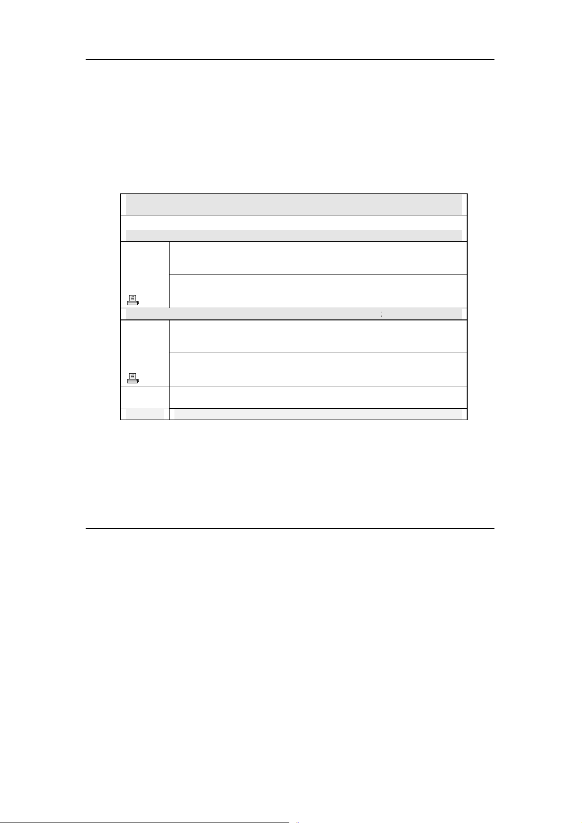
2. Click on Drivers & Utilities section and the system will run the
setup.exe automatically. Soon the Atheros Client Installation
Program screen appears.
3. Next, the Atheros Client Installation Program screen appears. Click
on the Next> button to proceed.
4
Page 13
Chapter 3 Wireless Adapter Installation
4. When the Licens e Agreement screen appears, you are required to
read and accept the agreement to continue. Click on the Next>
button to proceed.
5. Select your preferred setup:
Install Client Utilities and Driver (Recommended) option
You are recommended to select this setup type. This option will
install both the drivers and utility that support your USB adapter.
Install Driver Only option (For Windows XP user only)
5
Page 14

Chapter 3 Wireless Adapter Installation
Select this option if you are going to use the Wireless Zero
Configuration Utility to configure your USB adapter. Note that only
Windows XP comes with the Wireless Zero Configuration Utility.
Make Driver Installation Diskette(s)
Select this option if you wish to make a dupli cate copy of the dri vers
and store in the diskette/s.
6. Click on the Next> butto n and follow the instructions stated on the
screen.
6
Page 15
Chapter 3 Wireless Adapter Installation
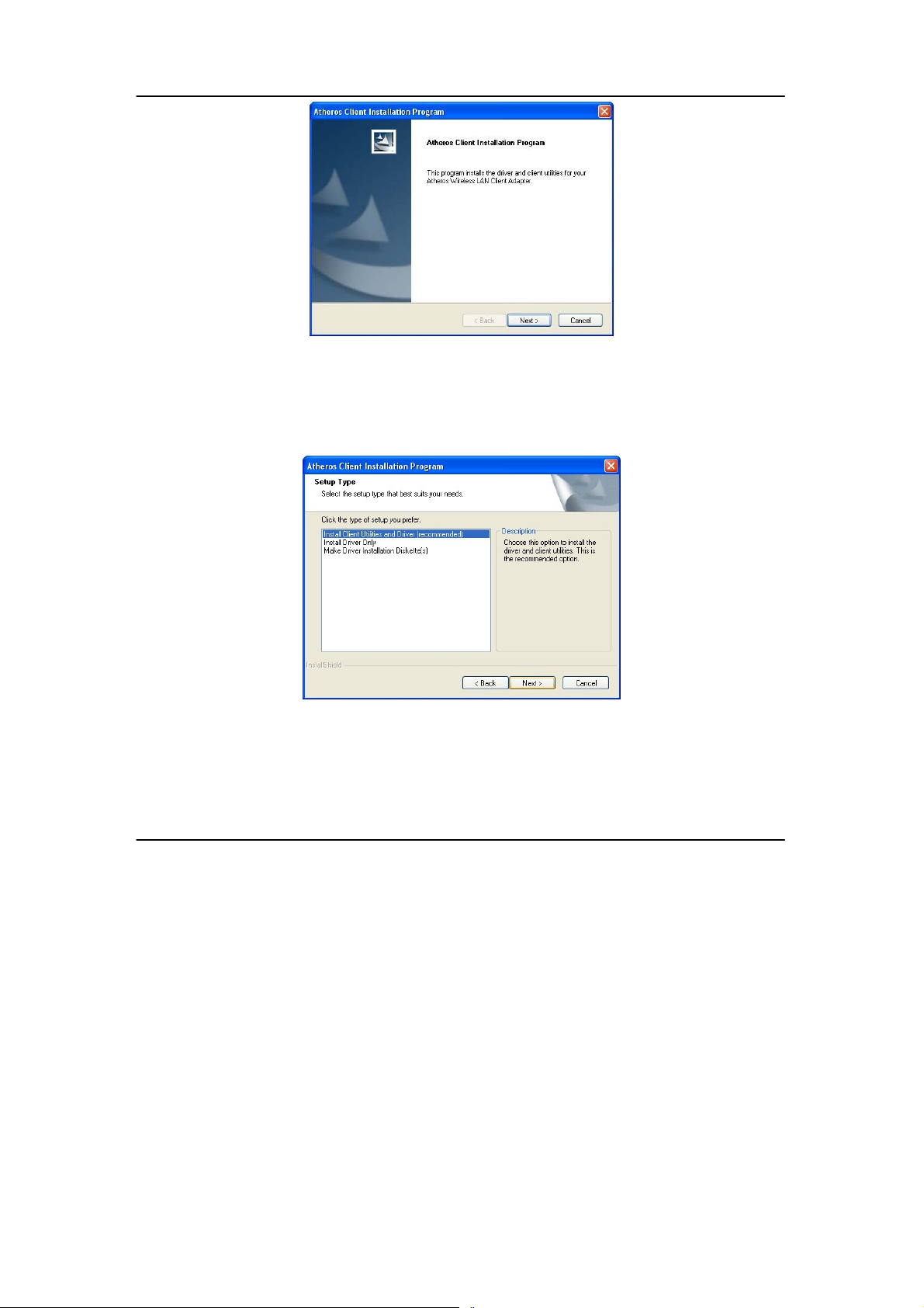
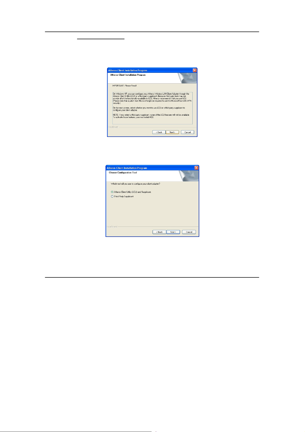
For Windows XP users
7. If you are using Windows XP as operating system, the following
screen will appear. Read the notice carefully and click on the Next>
button to proceed.
8. Select your choice of tool to assist you in configuring your USB
adapter. Click on the Next> button to proceed.
7
Page 16
Chapter 3 Wireless Adapter Installation
Atheros Client Utility (ACU) and Supplicant option
Select this option to install your USB adapter’s utility.
(Recommended)
Third Party Supplicant option
Select this option if you decide to use Wireless Zero Configuration
Utility to configure your wireless device. Installing this tool will only
allow you to view the status of the connected wireless device/s
through the USB adapter’s utility; configuration using the USB
adapter’s utility will not be allowed.
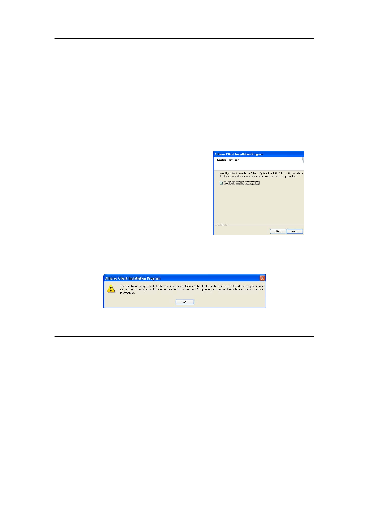
Third Party Supplicant option (continued..)
If you have selected Third Party Supplicant configuration tool, a
screen similar to that on the right will appear, prompting you to
enable/disable the system tray icon.
9. Click on the checkbox besides
Enable Atheros System Tray Utility
and click on the Next> button to
proceed.
10. The screen below appears to inform you that the driver will be
automatically installed if you have already inserted your client
adapter into the USB slot of your computer.
8
Page 17

Chapter 3 Wireless Adapter Installation
Cancel the Found New Hardware Wizard if it appears and click on
the OK button to begin the installation.
11. Click on the OK button to reboot your system and this will complete
the installation.
9
Page 18
Chapter 3 Wireless Adapter Installation
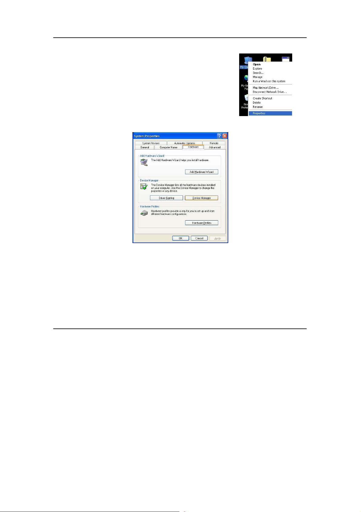
To confirm if the driver has been successful ly installed on your system,
1. Proceed to your desktop, right click on My
Computer and select Properties.
2. Select the Hardware tab and click on Device
Manager.
10
Page 19
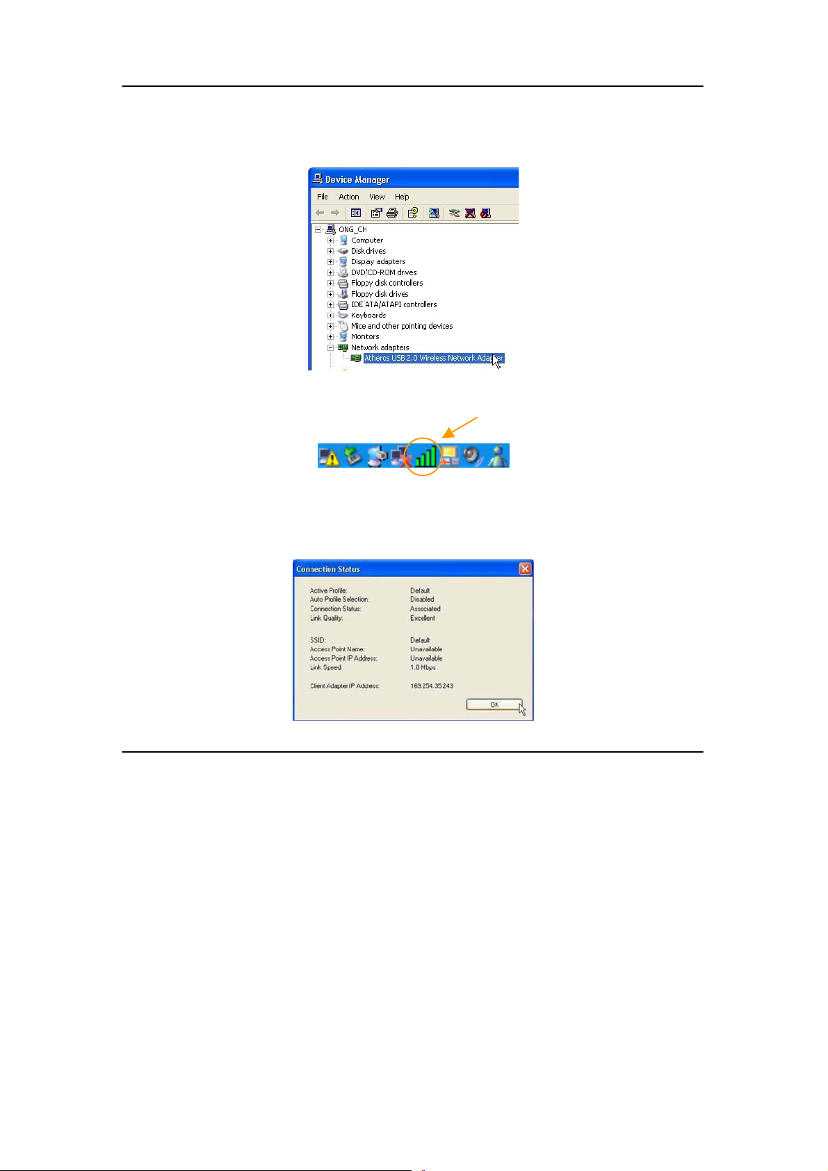
Chapter 3 Wireless Adapter Installation
The folder name, Atheros USB 2.0 Wireless Network Adapter will
appear in the Network Adapters section. This indicates that the
driver for the USB adapter has been successfully installed on your
system!
To activate the utility program, double click on the icon shown in the
system tray.
If you have double-click on the utility option, the following screen will
appear to give you a glimpse of your connection status . To exit i t, click on
the OK button.
11
Page 20

Chapter 3 Wireless Adapter Installation
To use the Atheros Client Utility, go to the Start Menu followed by
Programs. Then select Atheros. From Atheros, s elect Atheros Client Utility.
You may now start to configure your USB adapter.
12
Page 21
Chapter 4 Using the System Tray Utility
Chapter 4 Using the System Tray Utility
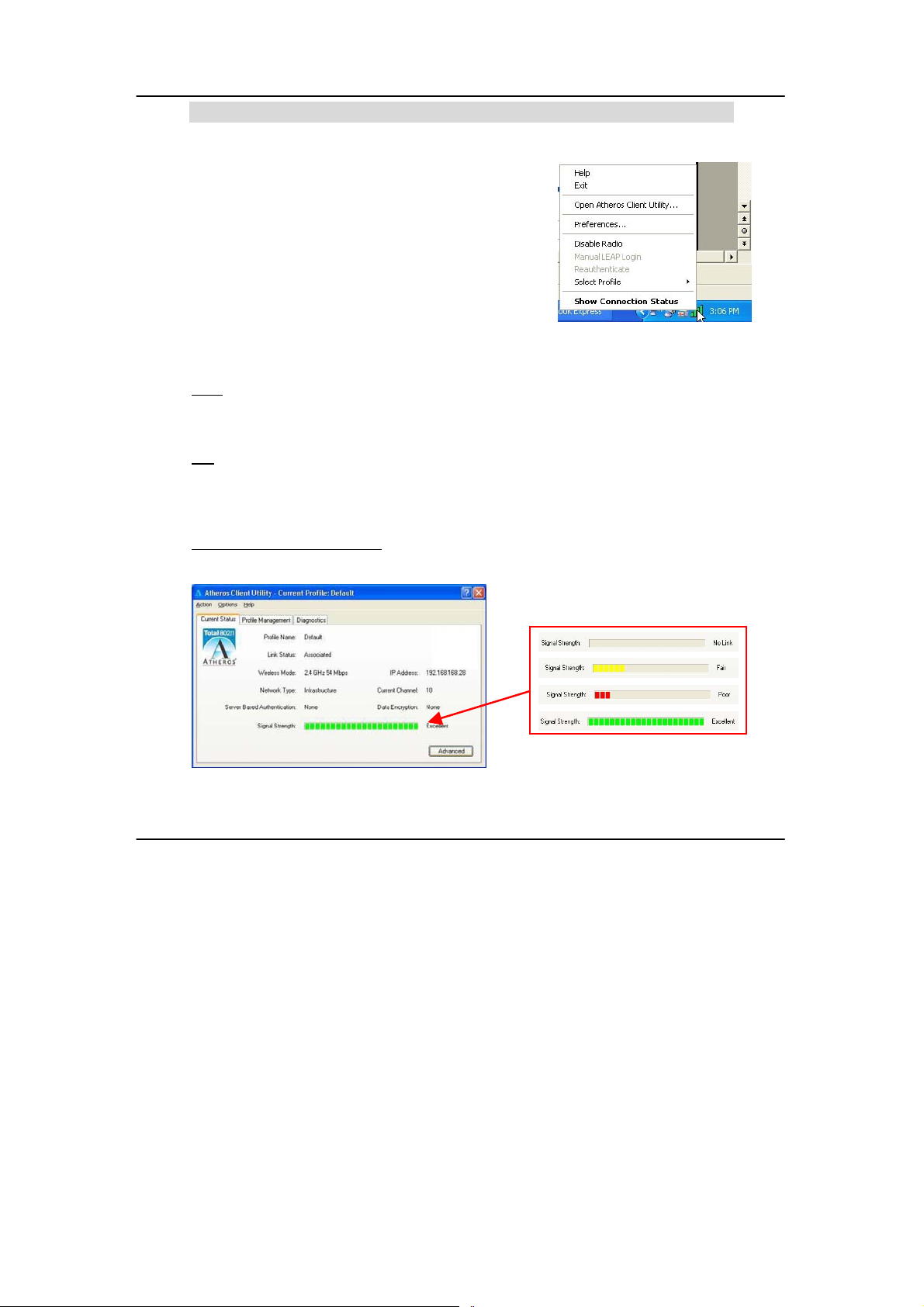
This chapter will elaborate on the Atheros system
tray utility found at the right bottom corner of your
screen. Right click on the utility icon and th e menu
will appear.
The following explains the different opti ons available on the menu:
Help
Open the online help.
Exit
Exit the Atheros Client Utili ty application. Once you exit, the i con will disappear
from the system tray.
Open Atheros Client Utility…
Launch the Client Utility.
Different signal strength indications
13
Page 22
Chapter 4 Using the System Tray Utility
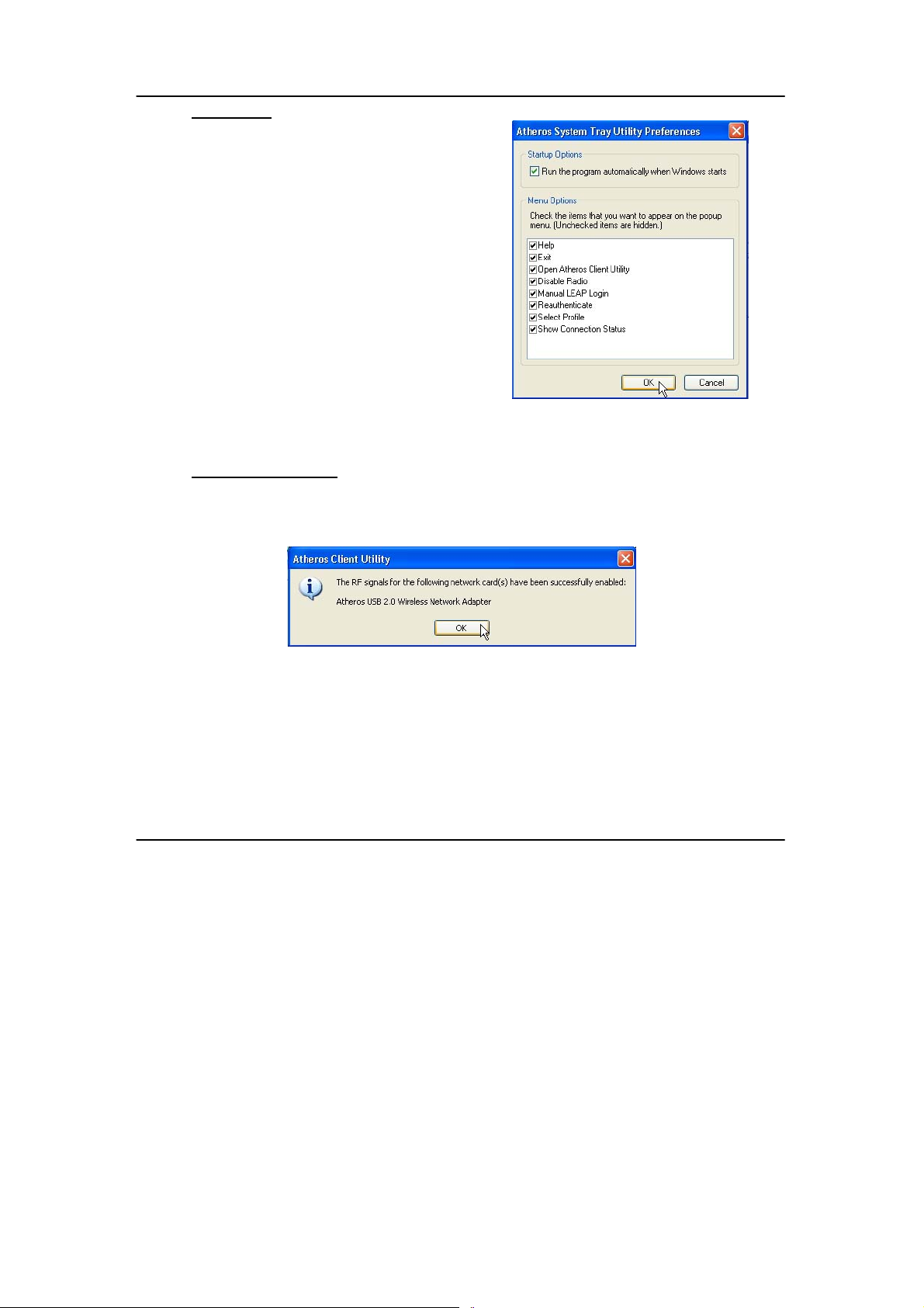
Preferences
This option allows you to set the startup and
menu options for the utility. You can deci de
whether the program should start
automatically when Windows starts, and
which menu items should appear on the pop
up menu.
Disable/Enable Radio
If you are unable to detect the RF signal, disable and enable the radio again.
Once the radio is enabled, the system will prompt you that the RF signals hav e
been successfully enabled.
Click on the OK button to proceed.
14
Page 23
Chapter 4 Using the System Tray Utility
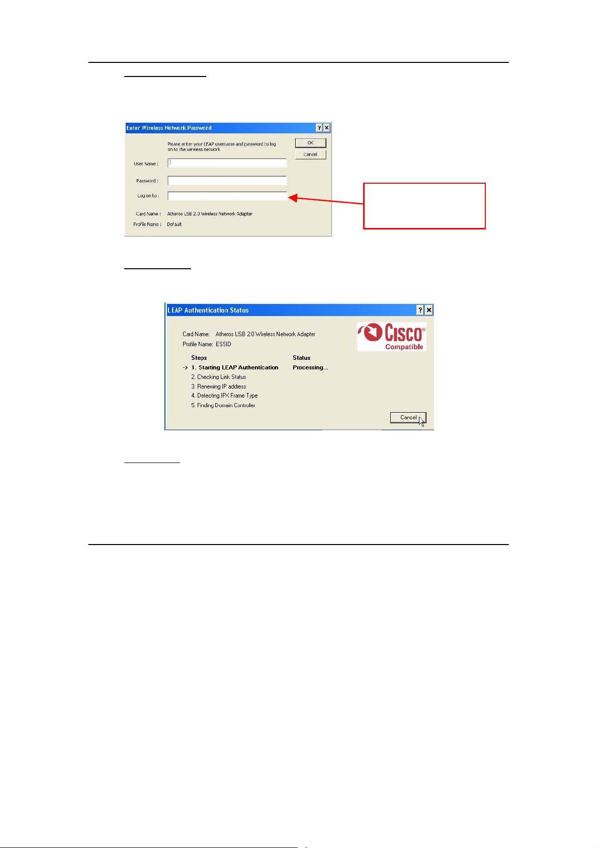
(
Manual LEAP Login
If you select this option, you will have to m anually start the LEA P authentication
process to login to the network instead of being prompted for your LEAP
username and password during your windows logon.
Optional) Enter the
domain name that you
wish to logon to.
Reauthenticate
Reauthenticate to a LEAP-configured access point each time you login to a
LEAP network.
Select Profile
Click on a configuration profile name to switch to a particular wireless network.
If no configuration profil e exists, you will need to add a profile first.
15
Page 24

Chapter 4 Using the System Tray Utility
Connection Status
To view the connection status of your wireless USB adapter.
Alternatively, you may also double click on the utility icon in the system tray.
Active Profile Displays the name of the active configurati on profile.
Auto Profile Selection Shows whether auto profile selection is enabled.
Connection Status Displays whether the adapter is connected to a
wireless network.
Link Quality States the quality of the link connection.
SSID Displays the SSID of the network to which the wireless
adapter is associated.
Access Point Name Shows the name of the access point the wirel ess
adapter is connected to (if any).
Access Point IP Address Shows the IP address of the access point the wireless
adapter is connected to (if any).
Link Speed States the speed of the link connection.
Client Adapter IP Address Displays the IP address of the wireless adapter.
16
Page 25
Chapter 5 Wireless Adapter Utility Features
Chapter 5 Wireless Adapter Utility Features
This chapter shows you how to make use of the util ity to view the status of your
wireless connection; to change your settings and also to monitor your wireless
performance via the statistics.
NOTE
It is advisable to activate only one of the utilities: Either the
Wireless Zero Configuration Utility OR the Atheros Utility.
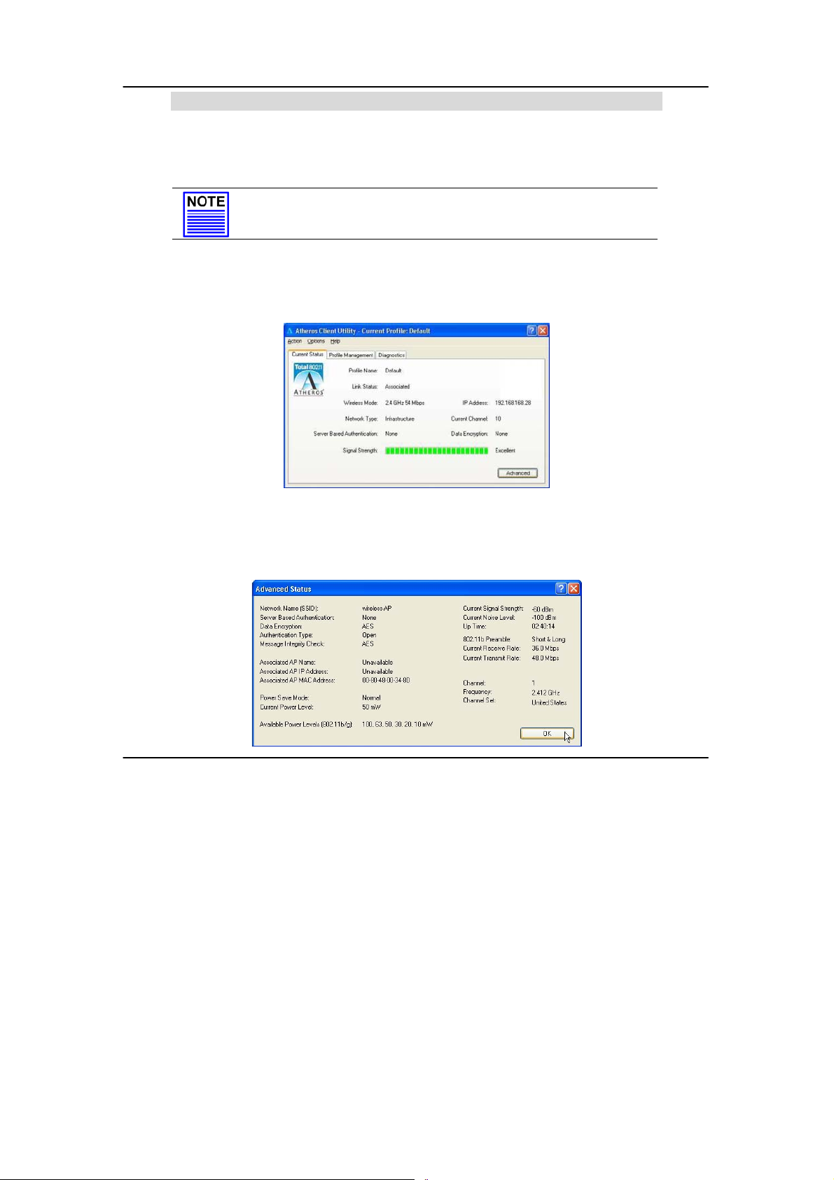
5.1 Current Status Tab
Displays the performance of the USB adapter in the wireless network.
Upon clicking on the Advanced button, you will be able to view all
information on the respective profile, e.g. the types of encryption and
authentication, the signal strength, the MAC address of the conn ected
AP (if you are in Infrastructure mode), etc.
17
Page 26

Chapter 5 Wireless Adapter Utility Features
5.2 Profile Management Tab
This option allows you to manage your profile, set your security options,
and scan for other wireless networks.
18
Page 27

Chapter 5 Wireless Adapter Utility Features
w
r
Click on New button to create a new profile. Enter the profi le name (a
unique name to identify thi s profile), a client name and the SSID of the
wireless network to connect to . Note that the Client name refers to the
name that is registered to your PC/notebook. You can enter up to 3
different SSIDs in order of preference, per profi l e. We are using ABC as the
profile name and APP as the SSID1.
For details on ho
to set the different
authentication and
encryption types
available unde
the Security Tab,
kindly refer to
Chapter 7 “Types
of Authentication
and Encryption
mode”
Click on the OK button to update the changes.
Notice that ABC has been added
to the profile list.
19
Page 28

Chapter 5 Wireless Adapter Utility Features
To modify an existing profile, select the profile that you wish to modify
and click on this button. We are using profile: Any as an example.
To delete an existing profile, select the particular profile that you wish to
delete and click on this button. We are using profile: default as an
example.
Note that the active profile (the profile that you are currently using)
cannot be deleted!
Active profile
indicated by this
icon cannot be
deleted!
20
Page 29

Chapter 5 Wireless Adapter Utility Features
To activate a profile, select the profi le and click on this button. We are
using profile: wireless-AP as an example.
Once a profile is activated, this icon will appear next to the profile
name: wireless-AP.
21
Page 30

Chapter 5 Wireless Adapter Utility Features
This function allows you to save the settings of your profile onto disk.
Select the profile that you wish to sav e and click on this button. We are
using profile: ESSID as an example.
Choose the folder to save to, enter the name under which to save the
profile and click on the Save button.
Now, your profile is saved to your selected folder.
22
Page 31

Chapter 5 Wireless Adapter Utility Features
This function allows you to retrieve a saved profile from disk. We are using
profile: ESSID as an example.
Go to the folder where you have saved your profile, select ESSID.prf and
click on the Open button.
Notice that the profile: ESSID has been imported to the list of profiles.
23
Page 32

Chapter 5 Wireless Adapter Utility Features
This function allows you to scan for wireless networks detected by the
adapter.
24
Page 33

Chapter 5 Wireless Adapter Utility Features
The icons shown beside the Network Name (SSID) indicate the type of
WLAN detected.
Connected to Infrastructure (AP)
Encryption Active
Notice that if there is a icon appearing in the Super column, this
shows that the wireless network supports Super-AG technology (108Mbps ).
Click on the Refresh button to renew the list of wireless networks detected.
Click on the OK button to exit the window.
25
Page 34

Chapter 5 Wireless Adapter Utility Features
If you have created several profil es, this function allows you to establish
the priority order in which the USB adapter should try to connect to a
WLAN. If the USB adapter is unable to connec t to the 1
try to connect to the 2nd profile and so on.
When auto profile selection is enabled,
the USB adapter scans for available
wireless networks and will connect to the
highest priority profile that matches the
networks detected.
To do so, simply click on the Add button
from the Available Profiles list. Refer to
the screen shown below.
Please note that you need AT LEAST TWO profiles to activate the Auto
Select Profiles function; and that each of your profile must connect to at
least one Network Name (SSID).
Notice that if this functi on is
disabled, this means that
you have not added any
profile in the Auto Selected
Profiles list.
st
profile, it will then
26
Page 35

Chapter 5 Wireless Adapter Utility Features
Notice that when a selected profile has been added, i t will be transferre d
to the Auto Selected Profiles list.
Select and click on the Add button to transfer another profile.
You need to transfer at least two profiles to the Auto Selected Profiles list
to activate the Auto Select Profile function.
27
Page 36

Chapter 5 Wireless Adapter Utility Features
5.2.1 Security Tab
Please refer to Chapter 7 “Types of Authentication and
Encryption mode”
5.2.2 Advanced Tab
This option allows you to configure the more advanced
connection settings of your wireless client.
28
Page 37

Chapter 5 Wireless Adapter Utility Features
r
Only applicable to
Infrastructure mode.
You may key in the MAC
address of at most fou
access points to which you
would prefer to connect.
Transmit Power Level
Specifies the wireless transmit power to be used. Reducing the power
level lowers the risk of interference with other nearby wireless devices and
conserves battery power but decreases radio range.
Power Save Mode (Only applicable to Infrastructure mode)
This feature reduces power consumption by the USB adapter to extend
the battery life of your notebook. There are 3 options for this mode:
• Off
The power management is disabled and the card consumes full
power from the computer.
• Normal
The driver turns off the power to the adapter for brief periods over
briefly spaced time intervals.
• Maximum
The driver turns off power to the adapter for longer periods over
more widely spaced time intervals.
29
Page 38

Chapter 5 Wireless Adapter Utility Features
The guideline for choosing between the Normal and Maximum
options:
The USB adapter wakes up more often and responds sooner to
network requests in Normal mode than in Maximum mode; and the
Maximum mode consumes less power than Normal mode.
Network Type
Select either Infrastructure if you are connecti ng to the WLAN using an
access point or Ad-hoc if you are connecting directly to another
computer equipped with a wireless adapter.
802.11b Preamble
The preamble is part of the IEEE 802.11 b physical layer specification. It is
mandatory for all 802.11b devices to support the long preamble format,
but they may optionally support the short preamble. This USB adapter
supports both the short and long preambles.
• Short & Long
This option allows communication with other 802.11b devices that
support short preamble to boost the throughput.
• Long
If your device is having trouble to communicate with other 802 .11b
devices, you may try to select the Long Only option.
Wireless Mode
Specifies 5GHz 54 Mbps, 2.4 GHz 54 Mbps, 2.4 GHz 11 Mbps, or Super A/G
operation in a wireless network where there is an access point.
The wireless adapter must match the wireless mode of the access point i t
associates to.
802.11 Authentication Mode (Only applicable to Infrastructure mode,
after you have enabled the encryption mode)
Select which mode the wireless adapter uses to authenticate to an
access point:
30
Page 39

Chapter 5 Wireless Adapter Utility Features
• Auto
Causes the adapter to attempt authentication using shared
authentication. It then switches to open authentication if shared
authentication fails.
• Open
Enables an adapter to attempt authentication regardless of its WEP
settings. It will only associate with the access poi nt if the WEP key of
the adapter matches that of the access point.
• Shared only
Allows the adapter to authenticate and associate only with access
points that have the same WEP key.
Note:
The USB adapter’s authenticati on mode setting s must match those of the
AP it is trying to connect to for successful com munication.
5.3 Diagnostics Tab
The Diagnostics tab lists the following receive and transmit di agnostics for
packets received by or transmitted to the USB adapter.
• Multicast packets transmitted and received
• Broadcast packets transmitted and received
• Unicast packets transmitted and received
• Total bytes transmitted and received
31
Page 40

Chapter 5 Wireless Adapter Utility Features
This button contains general information about the network interface
card (the wireless USB adapter) and the network driver interface
specification (NDIS).
Card Name The name of the USB adapter
MAC Address The MAC address of the USB adapter
Driver The driver name and path of the USB adapter’s driver
Driver version The version of the USB adapter’s driver
Driver date The creation date of the USB adapter’s driver
Client Name The name of the client computer
This button shows more detailed statis tical informati on on frames that are
either received by or transmi tted to the USB adapter.
32
Page 41

Chapter 5 Wireless Adapter Utility Features
33
Page 42

Chapter 6 Wireless Adapter Utility Configuration
Chapter 6 Wireless Adapter Utility Configuration
This chapter will elaborate on the Client Manager configuration of the USB
adapter using some simple examples.
6.1 Infrastructure Mode
In infrastructure architecture, the wireless clients communicate through
access points that are devices that act as base station for all wireless
communication. Data packets from the wireless clients are transferr ed to
the access points before being tran smitted to other hosts on the network.
The number of wireless clients supported depends on the access points.
34
Page 43

Chapter 6 Wireless Adapter Utility Configuration
6.1.1 Configuration on Infrastructure Mode
In this example, two notebooks and PC2 act as wireless clients to
communicate with the wireless AP. Once all configuration has been
done, wireless clients with the same SSID as the A P will be able to access
wirelessly to PC1 via the wireless AP.
For AP
Ensure that you have enabled the DHC P server in your access point and
that your wireless clients are set to receive their IP address dynamical ly so
that the wireless AP can assign an IP address to its wireless clients. Note
the wireless configuration settings of your access point as shown in the
figure above.
35
Page 44

Chapter 6 Wireless Adapter Utility Configuration
For PC 2
1. Activate your USB adapter’ s utility.
2. Go to the Profile Management tab, click on the Scan button to look
for the wireless AP.
3. Click on the Refresh button if your system is unable to detect your
wireless AP. Once found, select the Network Name (SSID) used by
the AP: Wireless-AP and click on the Activate button to add it to
your profile list.
36
Page 45

Chapter 6 Wireless Adapter Utility Configuration
Notice that the SSID has already been pre-config ured in this profile.
The SSID of both the wireless AP and the wireless client must be the same
for them to communicate with one another.
4. Enter the Profile Name, e.g. Workstation 2 for easy identification.
5. Next, proceed to the Security tab. The wireless client must use the
same security mode as the AP. In our example, select WPA
Passphrase and click on the Configure… button.
37
Page 46

Chapter 6 Wireless Adapter Utility Configuration
6. Enter the encryption key in the field provided. Please note that thi s
key must be the same as the one that you had configured for your
access point.
7. Click on the OK button to update the changes.
Proceed to your Current Status tab to monitor the connecti on between
the access point and the wireless client (PC2).
38
Page 47

Chapter 6 Wireless Adapter Utility Configuration
Alternatively, you can also check the connection from the MS-DOS
Prompt. From PC2, simply proceed to the Start Menu, Run… and type in
cmd. Click on the OK button.
In the MS-DOS Prompt window, type ping 192.168.168.1 –t , whereby this IP
address belongs to your access point.
When the screen appears:
Pinging 192.168.168.1: bytes=32 time=2ms TTL=128
Pinging 192.168.168.1: bytes=32 time=2ms TTL=128
Pinging 192.168.168.1: bytes=32 time=2ms TTL=128
…….
This indicates that the connection between the access point and the
wireless client has been established successfully! You can no w access to
one another wirelessly!
39
Page 48

Chapter 6 Wireless Adapter Utility Configuration
For the rest of the workstations
Refer to the steps for configuring PC2.
If your other wireless clients are not using the USB adapter , you may refer
to the manual of these other adapters for details on Ad-hoc
configuration.
For details on other authenti cation and encryption types, kindly refer to
Chapter 7 “Types of Authentication and Encryption mode”
40
Page 49

Chapter 7 Types of Authentication and Encryption mode
x
Chapter 7 Types of Authentication and Encryption mode
This chapter illustrates the di fferent types of authenti cation and encryption tha t
can be used in the wireless LAN.
7.1 Infrastructure Network Security
Extensible Authentication Protoc ol (EAP) is used to authenticate network
clients before letting them access the enterprise network. It allows the
network administrator to create an arbitrary authentication scheme
(such as EAP-TLS, etc) to validate network access.
7.1.1 EAP-TLS
Extensible Authentication Protoc ol-Transport Layer Security (EAPTLS) makes use of client-side and server-side certificates for
mutual authentication.
To use EAP-TLS security, access the Security tab in the Profile
Management window.
1. You can select
WPA radio button
Or
802.1x radio button
(802.1x enables 802.1x security.
If the access point that the wireless adapter is
associating to has WEP set to Optional while
the wireless adapter has WEP enabled, ensure
that Allow Association to Mixed Cells is
checked to allow association.
Note that this opti on i s av ai labl e onl y i n 802.1
and Pre-Shared Key (Static WEP).
41
Page 50

Chapter 7 Types of Authentication and Encryption mode
2. Choose EAP-TLS from the drop-down menu and click on the
Configure… button.
NOTE
To enable this security, you must ensure that your PC/notebook
has already downloaded its EAP-TLS certificates. Check with your
system administrator for details.
3. If your system does not support EAP-TLS, the following
message will pop up:
7.1.2 EAP-TTLS
If EAP-TLS is supported, select the appropriate certificate
authority from the list. The server/domain name and the login
name are filled in automatically from the certificate
information.
4. Click on the OK button twice to activate the profile.
EAP-TTLS (Tunnel Transport Layer Security) authentication is an
extension to EAP-TLS. It uses certificates and EAP-TLS to
authenticate the server only and establish an encrypted tunnel .
Then within that tunnel, the client authenticates to the server
using either a username and password or a token card.
42
Page 51

Chapter 7 Types of Authentication and Encryption mode
To use EAP-TTLS security, access the Security tab in the Profile
Management window.
1. You can select
WPA radio button
Or
802.1x radio button
2. Choose EAP-TTLS from the drop-down menu and click on the
Configure… button.
3. Select the appropriate certification authority (CA) from
which the server certificate will be downloaded from the
Trusted Root Certification Authorities drop-down list.
4. The EAP username is pre-defined in the User Name field. IF
not, specify your username (which is registered with the
43
Page 52

Chapter 7 Types of Authentication and Encryption mode
server) for EAP authentication. Enter your password in both
the Password and Confirm Password fields.
5. Click on the Advanced… button.
6. Leave the specification server/domain field blank to allow
the client to accept a certificate from any server that
supplies a certificate signed by the CA listed previ ously. The
login name is pre-defined in the Login name field.
7. Click the OK button.
44
Page 53

Chapter 7 Types of Authentication and Encryption mode
7.1.3 PEAP (EAP-GTC)
The PEAP (EAP-Generic Token Card) method is intended for use
with Token Cards supporting challenge /response authentication
and MUST NOT be used to provide support for clear text
passwords in the absence of a protected tunnel with server
authentication.
To use PEAP-GTC security, access the Security tab in the Profile
Management window.
1. You can select
WPA radio button
Or
802.1x radio button
45
Page 54

Chapter 7 Types of Authentication and Encryption mode
2. Choose PEAP-GTC from the drop-down menu and click on
the Configure… button.
NOTE
To enable this security, you must ensure that your PC/notebook
has already downloaded WPA-PEAP certificates; and the server
properties must already be set. Check with your system
administrator for details.
3. Select the appropriate certi ficate authority (CA) from which
the server certificate is downloaded from the drop-down list.
4. Enter your PEAP username (which is register ed with the serv er)
in the User Name field.
5. Specify whether yo u are using a Token or a Static Password.
Click on the Advanced button.
Note that the Token can take the form of hardware token
device or the Secure Computing SofToken Program (version
1.3 or later) to obtain and enter a one-time password for
authentication.
6. Leave the specification server/domain field blank to allow
the client to accept a certificate from any server that
supplies a certificate signed by the CA listed previousl y.
7. The l ogin name will be pre-defined in the field provided . This
login name is used for PEAP tunnel authentication. It will be
filled in automatically as PEAP-xxxxxxxxxxxx, where
xxxxxxxxxxxx is the computer’s MAC address. You may
46
Page 55

Chapter 7 Types of Authentication and Encryption mode
change the login name if needed. Cli ck on the OK button to
save your settings.
7.1.4 PEAP (EAP-MSCHAP V2)
Microsoft-Challenge Handshake Authentication Protocol V2 (MSCHAP V2) is a mutual authentication protocol that requires both
the client and server’s identiti es to be proven. If your connec tion
is configured to use MS-CHAP V2 as its only authentication
method, and the server that you are connecting to does not
provide proof of its identity, your connection disconnects.
To use PEAP-MSCHAP V2 security, access the Security tab in the
Profile Management window.
1. You can select
WPA radio button
Or
802.1x radio button
47
Page 56

Chapter 7 Types of Authentication and Encryption mode
2. Choose PEAP (MS-CHAPV2) from the drop-down menu and
click on the Configure… button.
NOTE
To enable this security, you must ensure that your PC/notebook
has already downloaded WPA-PEAP certificates; and the server
properties must already be set. Check with your system
administrator for details.
3. Enter your PEAP username and password (which are
registered with the server) in the User Name and Password
field respectively. Re-type the password in the Confirm
Password field.
4. Click on the Advanced button.
5. Leave the specification server/domain field blank to allow
the client to accept a certificate from any server that
supplies a certificate signed by the CA listed previousl y.
6. Click the OK button to enable the profile.
48
Page 57

Chapter 7 Types of Authentication and Encryption mode
7.1.5 LEAP
Lightweight Extensible Authentication Protocol (LEAP) security
requires all infrastructure devices (e.g. access poi nts and servers)
to be configured for LEAP authentication.
To use LEAP security, access the Security tab in the Profile
Management window.
1. You can select
WPA radio button
Or
802.1x radio button
49
Page 58

Chapter 7 Types of Authentication and Encryption mode
2. Choose LEAP from the drop-down menu and click on the
Configure… button.
3. You may set your username and password to:
- Use Temporary User Name and Password
Each time your PC reboots, you will be require to enter
your LEAP username and password in order to be
authenticated and obtain access to the network.
- Use Saved User Name and Password.
Authentication is obtained using a saved username and
password (registered with the server) so you will not be
require to enter your LEAP username and password each
time your PC reboots.
Temporary User Name and Password
1. The login page will pop up as shown below. Fill up the
respective fields and cli c k on the OK button twic e.
Next, the system will start the LEAP authentication.
50
Page 59

Chapter 7 Types of Authentication and Encryption mode
Saved User Name and Password
1. Enter the username, password and re-enter password in
Confirm Password field.
(Optional) You may enter a specific domain name, which
will be passed to the server.
2. Enter the LEA P authentication timeout (between 30 and 500
seconds) to specify how long LEAP should wait before
considering an authentication as failed, and sending an
error message. The default is 90 seconds.
3. Click on the OK button.
51
Page 60

Chapter 7 Types of Authentication and Encryption mode
g
g
g
k
r
Check the Include
Windows Lo
with User Name option
to automatically send
your Windows lo
domain to
your user name to the
RADIUS server. (Default)
Check the No Networ
Connection Unless Use
Is Logged In option to
force the wireless
adapter to disassociate
after you log off.
on Domain
in
ether with
7.1.6 WPA Passphrase
WPA Passphrase is also known as WPA-PSK (Pre-shared Key). It
provides strong encryption protection for home/SOHO users who
do not use an enterprise authentication server.
1. Click on the WPA Passphrase radio button and click on the
Configure… button.
52
Page 61

Chapter 7 Types of Authentication and Encryption mode
2. Enter the password and click on the OK button.
Note:
The WPA Passphrase must match that used by the AP/other
wireless clients in the network.
7.1.7 Pre-shared Key (Static WEP)
Wired Equivalent Privacy is a security protocol that allows the
wireless client adapter to comm unicate ONLY with ac cess points
or other wireless clients that have the same WEP key.
WEP Key is categorized into two types: Hexadecimal and ASCII.
Hexadecimal values consist a to f and numbers 0 to 9 whereas
ASCII valu es consist of alphanumeric characters a to z; 0 to 9.
53
Page 62

Chapter 7 Types of Authentication and Encryption mode
x
To define pre-shared encryption keys,
1. Choose the Pre-shared Key (Static WEP) radio button and
click the Configure… button to fill i n the encryption key.
If the access point that the wireless adapter is
associating to has WEP set to Optional while
the wireless adapter has WEP enabled, ensure
that Allow Association to Mixed Cells is
checked to allow association.
Note that this opti on i s av ai labl e onl y i n 802.1
and Pre-Shared Key (Static WEP).
2. Enter your WEP key and click on the OK button.
54
Page 63

Chapter 7 Types of Authentication and Encryption mode
WEP Key size
- 64-bit WEP: 10 hexadecimal or 5 ASCII Text
- 128-bit WEP: 26 hexadecimal or 13 ASCII Text
- 152-bit WEP: 13 hexadecimal or 16 ASCII Text
55
Page 64

Appendix I Remove USB Adapter from the System
Appendix I Remove USB Adapter from the System
To safely remove your USB adapter from your system,
1. From the system tray, go to Safely Remove Hardware icon and click Safely
Remove Hardware.
2. Select Atheros USB 2.0 Wireless Network Adapter and click on the Stop
button to terminate all activities.
56
Page 65

Appendix I Remove USB Adapter from the System
3. Next, select Atheros USB 2.0 Wireless Network Adapter to confirm you will
be removing it from the USB port and click on the OK button.
4. The system will then inform you that the device can now be safely
removed from the system.
5. Click on the Close button to exit this window.
57
Page 66

Appendix II Un-install Wireless Adapter
Appendix II Un-install Wireless Adapter
Please note that in case there is a software upgrade for the wireless adapter,
you will need to un-install the current softwar e version before installing the ne w
software.
When you un-install the USB adapter’s software, any existing profiles will be
removed. If you want to re-use your profiles, please refer to Section 5.2 Profile
Management Tab for further details on how to export a profile to disk. You are
advised to close all programs and to leave the USB adapter in the USB slot of
your PC/notebook before un-installing your USB adapter.
1. From your Start menu, go to Settings, Control Panel and then cli ck on the
Add or Remove Programs icon.
2. Highlight the Atheros Client Installation Program and click on the
Change/Remove button.
58
Page 67

Appendix II Un-install Wireless Adapter
3. Wait until you see the Atheros Client Installation Program screen. Select
Uninstall the previous installation. Then click on the Next> button to
proceed.
4. The prompt scree n appears to notify you that the uninstall option requi res
the system to be rebooted at the end of the uninstall process. Click on the
Yes button to proceed.
5. Your system will prompt you to confirm whether you want to remove th e
application completely. Click OK to proceed.
59
Page 68

Appendix II Un-install Wireless Adapter
6. You will be asked to decide whether to remove the device driver or not.
Click on the Yes button to accept.
7. The uninstall process will then begin. Soon the pro mpt screen will appear
informing you that the uninstal l process is successful, and that your system
needs to be rebooted.
8. Click OK to reboot the system.
60
Page 69

Appendix III Certificate Application for WPA mode
Appendix III Certificate Application for WPA mode
The USB adapter supports WPA and WPA-PSK mode in Windows 2000/XP.
WPA is a specification of standards-based, interoperable security
enhancement that strongly increases the l evel of data protection (encryption)
and access control (authentication) in your wireless network. The technical
components of WPA include Temporal Key Integrity Protocol (TKIP) for dynamic
key exchange, and 802.1x for authentication.
WPA requires a RADIUS Server to complete the au thentication among wireless
stations and Access Points. Typically, this mode is used in an enterprise
environment. WPA-PSK does not require a RADI US Server and is very conv enient
for home/SOHO users. In this chapter, we will explain how to apply for a
certificate in order to access to a wireless network usi ng WPA mode.
NOTE
For Windows XP users with Service Pack 1 (SP1), you need to
upgrade to SP2, available from the Microsoft website or to install
the two patch files provided in the Product CD.
Overall procedures to apply certificate for WPA mode
• Install Windows XP Service Pack 2
• Apply certification via Internet Browser
• Become domain member
61
Page 70

Appendix III Certificate Application for WPA mode
AIII.I Installing Window XP Service Pack Patch File (For Windows XP
users)
To check whether you have already
installed Windows XP SP2, go to My
Computer, right click and select
Properties.
If you are using the Windows XP SP1 and do not intend to upgrade to SP2,
you will need to install the two patch files provided in the Product CD.
1. After ensuring that you have installed Windows XP SP1, insert your
Product CD into your CD-ROM drive, go to Drivers & Utilities section,
select to install WindowsXP- Q815485_WXP_SP2_x86_ENU.exe
followed by WindowsXP-KB826942-x86-ENU.exe.
You may need to restart
your PC to complete the
installation.
62
Page 71

Appendix III Certificate Application for WPA mode
AIII.2 Installing certificate on your server
If you are using Microsoft Certificates services,
1. Click on the Install this certificate link in the window to start the
installation.
Chapter 8 Click on the Yes button on the pop up window to
continue with the installation.
Chapter 9 To add the certificate to the Root Store, click on the
Yes button.
63
Page 72

Appendix III Certificate Application for WPA mode
Chapter 10 The following window will appear showing that the
certificate has been successfully installed into your
PC.
AIII.3 Applying for Client Certifications
If you have installed Microsoft SP2 or Microsoft XP SP1 with the 2 patch
files provided on the Product CD, you are now ready to apply for a
certificate for your wireless client.
At this stage, ensure that your wireless client has conn ectivity to the CA
server. You should disable your key encryption.
1. Open your Internet browser; enter e.g. http://192.168.88.26/certsrv
where 192.168.88.26 is the server’s IP address.
64
Page 73

Appendix III Certificate Application for WPA mode
Chapter 11 Next, you need to
connect to your
server in order to get
a certification. Enter
the username and
password that are
provided by your
system administrator.
Chapter 12 Once you get connected to your server, the
following screen shot will appear. Select the
Request a certificate radio button and click on the
Next> button. Follow the instructions shown on the
screen.
The screen below will appear to indicate that a certificate has been
successfully issued to your PC.
65
Page 74

Appendix III Certificate Application for WPA mode
Chapter 13 To confirm whether you have
received your certificate, go
to your web browser and
select Internet Options… from
your Tools pull down menu.
Chapter 14 Go to the Content tab and click on the
Certificates… button. Notice that your username is
in the listing. This shows that the certificate has been
issued to you.
66
Page 75

Appendix III Certificate Application for WPA mode
AIII.4 Becoming a domain member
Next, you need to add your username in the domain so that you can
communicate with the access point connected to your server.
1. From the My Computer icon on your
desktop, right click and go to Properties.
Chapter 15 Go to the Computer Name tab
and select Change… button
as shown in the screen on the
right.
Chapter 16 From the Member of section, select the Domain:
radio button and enter the name of your domain. In
67
Page 76

Appendix III Certificate Application for WPA mode
this example, we are using test as the domain
name.
Chapter 17 Next, you need to enter your username and
password again for verification. Please note that
your system administrator provides this information.
Chapter 18 Click on the OK button to proceed.
68
Page 77

Appendix III Certificate Application for WPA mode
Chapter 19 When done, a message will appear as shown below.
You may need to restart your computer for the
changes to take effect.
69
Page 78

Appendix IV Wireless Zero Configuration Utility
Appendix IV Wireless Zero Configuration Utility
If your computer is running under the Windows XP operati ng system, you can
opt to configure the Wireless Network Connection from your Windows XP
operating system, instead of the Atheros Utility. You need to exit from the
Atheros Utility before accessing to Windows XP’s Wireless Zero Configuration
Utility.
AIV.1 Enable Wireless Zero Configuration Utility
To set Wireless Zero Configuration on Windows XP, take the following steps:
1. From the system tray, right cli ck on the
Wireless Network icon and select View
Available Wireless Networks option.
2. Click on the Change advanced settings option on the left-hand
column.
70
Page 79

Appendix IV Wireless Zero Configuration Utility
Chapter 20 Select the check box Use Windows to configure my
wireless network settings to activate Wireless Zero
Configuration Utility.
When this check box is selected, Windows XP takes control of these
settings for all configuration profiles:
- SSID
- Security Keys
- Ad-hoc settings
71
Page 80

Appendix IV Wireless Zero Configuration Utility
When the Wireless Zero Configuration Utility is in use, a pop-up
message is displayed on the Utility when you attempt to create or
edit a configuration profile from the Profile Management tab of the
utility.
CAUTION
If you activate BOTH (not recommended) the Wireless Zero
Configuration Utility and the Atheros Utility simultaneously, the
Profile setting configured by the Atheros Uti lity will be overridden
by those of the Wireless Zero Configuration Utility.
AIV.2 Disable Wireless Zero Configuration Utility
To turn Wireless Zero Configuration Utility off on Windows XP,
1. Open the Wireless Zero Configuration Properties dialog box.
Chapter 21 Clear the check box Use Windows to configure my
wireless network settings.
Chapter 22 When this check box is cleared, all profile settings
will be controlled by the USB adapter’s utility.
72
Page 81

Appendix V Panel Views and Descriptions
Appendix V Panel Views and Descriptions
Components Indications & Descriptions
1 Power Green Indicates that power is being supplied
to the USB adapter.
2 USB Connector Connect this end to the USB port of your
PC/notebook.
3 MC Connector
(Version MC)
4 Hook As a strap holder to prevent the USB adapter form
Connect the testing line to the MC connector.
being lost or carelessly dropped.
73
Page 82

Appendix VI Technical Specifications
Appendix VI Technical Specifications
Network Protocol, Standards and Electrical Emissions
Industry Standards • IEEE 802.11b/g
• IEEE 802.11b/g/A (Version AG)
• USB 2.0
Performance
Frequency Band
IEEE 802.11g:
IEEE 802.11b:
IEEE 802.11a (Version AG):
Data Rates
(with automatic fallback)
Modulation • BPSK (Binary Phase Shift Keying)
Radio Technology • DSSS (Direct Sequence Spread Spectrum)
Drivers/Operating system
Supported
Media Access Protocol Carrier Sense Multiple Access with Collision
RF Output Power
2.400 ~ 2.4835GHz (US, Canada)
5.15-5.35GHz;5.725-5.85GHz
108Mbps, 54Mbps, 48Mbps, 36Mbps, 24Mbps,
18Mbps, 12Mbps, 11Mbps, 9Mbps, 6Mbps,
5.5Mbps, 2Mbps, 1Mbps
• QPSK (Quadrature Phase Shift Keying)
• CCK (Complementary Code Keying)
• 16 QAM, 64 QAM (Quadrature Amplitude
Modulation)
• OFDM(Orthogonal Frequency Division
Multiplexing)
Windows XP/2000
Avoidance (CSMA/CA)
15 dBm (typical)
74
Page 83

Appendix VI Technical Specifications
Receiver Sensitivity -95 dBm at 1Mbps (typical)
-92 dBm at 6Mbps (typical)
-90 dBm at 11Mbps (typical)
-73 dBm at 54Mbps (typical)
Host Interface USB 2.0
Security • 64/128/152-bit WEP encryption
• IEEE 802.1x supports – EAP-TLS,EAP- TTLS,
PEAP-GTC, PEAP_MSCHAP V2, LEAP
• WPA, WPA-PSK
Physical and Environment
Environmental Requirements
Operating temperature:
Storage temperature:
Operating humidity:
Non-operating humidity:
Power Consumption 5V DC, 500mA max
Physical Dimensions 87mm x 26.6mm x 7.7mm
0°C to 55°C
-20°C to 70°C
10% to 70% RH
5% to 90% RH
75
 Loading...