

COMP Cams 6300 Hi-Tech Belt Drive Systems User Manual
COMP Cams®
3406 Democrat Rd.
Memphis, TN 38118
Phone: (901) 795-2400 Fax: (901) 366-1807
www.compcams.com
Part #188
Revised 3/14/08
INSTRUCTIONS
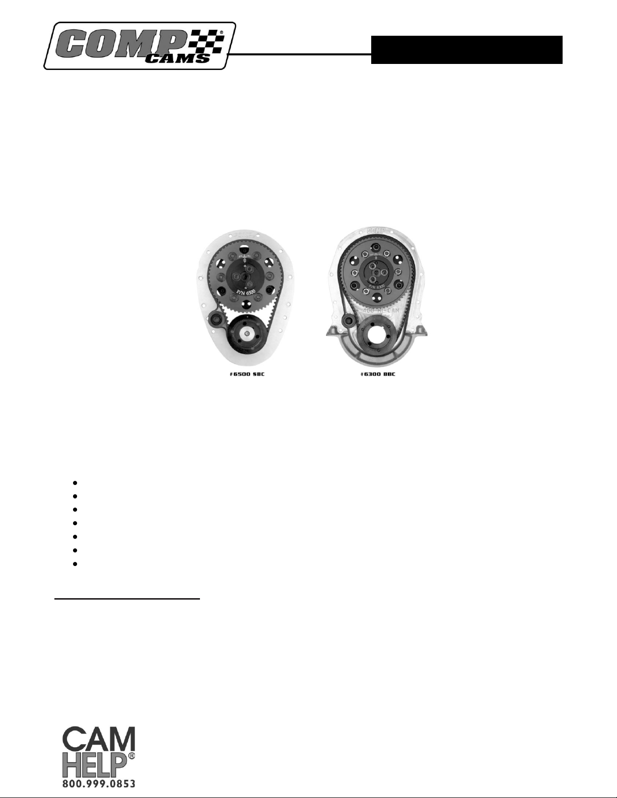
Hi-Tech™ Belt Drive Systems
Small Block Chevrolet #6500, 6502, 6504, 6506 & 6507
Big Block Chevrolet #6200 and 6300
Thank you for choosing COMP Cams® products; we are proud to be your manufacturer of choice. Please read
this instruction sheet carefully before beginning installation, and also take a moment to review the included
limited warranty information.
COMP Cams® belt drives represent the ultimate in cam timing systems. Our belt drives are designed to absorb a
significant amount of crankshaft harmonics, which will affect valve motion if they reach the valve train. COMP
Cams® belt drives require less power to operate than conventional belt drives. Last but not least, our belt drives
have proven to be more durable than either gear or chain drives.
Excellent for all NASCAR and NHRA applications
Unique camshaft thrust adjustment system does not require the use of shims to set end play
Belt idler reduces belt “flap”
High performance belt
Idlers available in different diameters for align bored blocks
Adjustable camshaft timing with simple Vernier sprocket
Double lip oil seals ensure maximum crankcase vacuum
Installation Instructions:
NOTE: The COMP Cams® Chevrolet belt drive system can be installed on an assembled engine.
However, the installing mechanic should be prepared to remove the camshaft for the purpose of
drive hub installation and end play adjustment.

COMP Cams®
3406 Democrat Rd.
Memphis, TN 38118
Phone: (901) 795-2400 Fax: (901) 366-1807
www.compcams.com
Part #188
Revised 3/14/08
Step 1: Disassemble the unit. It comes from the factory with several components assembled for protection during
shipping. Unbolt the camshaft pulley from the drive flange and separate the flange from the cam hub. This is done
by removing three 5/16 cap screw head bolts and using a drift punch or driver to separate the flange and hub (fig.
1). Remove the belt tensioner from the rear belt cover. Also, remove the camshaft endplay adjustment housing
(three Allen bolts)
Step 2: Trial fit front cover to make sure it clears the block. Much detail has been
given to fitment and most covers will not require modification. If required, use a die
grinder or mill to remove excess material from cover and/or block. Take steps to
prevent removed material from contaminating engine.
Step 3: Install front cover on engine using supplied gaskets and fasteners. Torque the
front cover bolts to 7-10 ft lbs of torque.
Step 4: Install crank pulley on crankshaft snout. Lubricate
the bore and seal area of the crank pulley with COMP
Cams® pro cam lube, part # 152. Use COMP® part #4789 crank gear installation tool and
#4920 harmonic balancer installation tool to press pulley onto snout or a section of 2-1/4"
o.d. x .375" wall aluminum tubing (fig. 2) as a driver. Caution: Be certain that the
crankshaft snout is not marred and that the crank hub seats squarely on the crank’s
shoulder step.
Step 5: Ensure that the front face of the camshaft is clean and free of surface burrs.
Any minor imperfections may be removed with a fine grit knife sharpening stone.
Install cam hub on camshaft (you may need to tap into place using a plastic mallet,
etc.). If needed, brace the camshaft by its bearing journals in a vise, being sure to pad
the jaws with wood or plastic to prevent damage to the camshaft. Use supplied 5/16" x
1" cap screws to secure hub. Add a small amount of medium strength thread locking
adhesive and tighten bolts to 18-22 ft lbs of torque (fig. 3).
Step 6: Lubricate roller thrust bearing with engine oil and install on backside of cam
hub. You can slide the bearing over the camshaft. Be sure that black-colored side of the
thrust bearing seats on the cam hub (fig. 4).
Step 7: Install camshaft in engine and place other roller thrust bearing on front side of
the hub (with black surface of bearing contacting the hub).
Step 8: Make sure cam hub and bearings are seated squarely on face of the engine block.
Any irregularities may cause a premature bearing and/or hub failure.
Step 9: Remove o-ring from camshaft end play
adjustment housing, install housing on the cam hub and
make sure seal is properly seated. Rotate housing
clockwise until it bottoms out on ramp. Gradually rotate
housing counterclockwise until desired camshaft
endplay is achieved. An endplay range of .002" to .007"
is suggested. However, this is ultimately left to the
discretion of the installing mechanic (fig. 5). The
assembly is designed so that each adjustment point
during rotation (where bolt holes line up) is equal to
.005". Once the desired endplay has been achieved, mark the housing and front cover at the appropriate bolt hole
with a felt tip pen as an indicator for reassembly (fig. 6). A scribe may also be used to mark the housing and front
 Loading...