

COMP Cams 4799 Timing Chain User Manual
Timing Chain Installation
Thank you for choosing COMP Cams® products; we are proud to be your manufacturer of choice. Please read
this instruction sheet carefully before beginning installation, and also take a moment to review the included
limited warranty information.
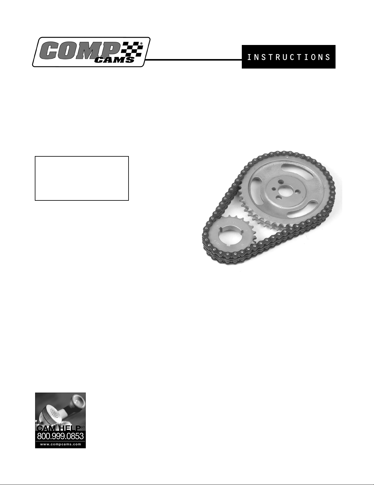
Kit Components:
o Upper timing gear
o Lower timing gear
o Timing chain
Tools and Supplies Needed:
1. Basic hand tools as required for your
particular camshaft balancer bolts.
2. Torque Wrench
3. Harmonic Balancer Installation Tool (Part
#4920, for units with press on balancer).
4. Crankshaft Timing gear Installation Tool
(Part # 4933 to be used in conjunction with #4920. For units with press on crankshaft gear only).
5. Pro Cam Lube (Part #153 or #154)
6. Camshaft Degree Kit (Part #4796 including degree video)
7. Crankshaft Socket (For your particular application)
Part #4793 Chevy Small Block 265-400, 90º V6, Pontiac and GM 4 cylinder
Part #4797 Chevy Big Block
Part #4798 Ford 289-351W, 429-460, Pontiac 389-455, and Buick
Part #4799 Chrysler V8, “LA”, “RB”, and Hemi
8. Thread Locking Compound
9. Engine Repair Manual for your particular engine
Revised 1/7/04
Competition Cams, Inc
3406 Democrat Rd.
Memphis, TN 38118
(901)795-2400 FAX (901)366-1807
www.compcams.com
Part #174

The following instructions begin after the timing cover and old timing set have been removed. Installing the
timing set and degreeing the camshaft will be easier if you loosen the rocker arms so that the camshaft can turn
freely. You should be able to turn the camshaft by hand. Make sure that the engine mounting surfaces and your
new timing set has been thoroughly cleaned with a good solvent. If you are using a timing set with three
keyways, select the appropriate keyway for your camshafts timing specifications. COMP Cams® recommends
the standard timing position for most applications. This position uses the round or “O” timing mark and round or
“O” keyway mark.
Standard Timing Location: This is the same as original O.E.M. setting. Use keyway marked “O” and
crankshaft gear tooth marked “O”.
4 Degree Advance: Use keyway marked “∆” (triangle) and the crankshaft gear tooth marked “∆” (triangle).
Note: The “∆” or advanced position should not be used without degreeing the camshaft. Many camshafts
have the proper advance built into the camshaft. Advancing the camshaft will reduce the intake valve to
piston clearance and increase exhaust piston to valve clearance.
4 Degree Retard: Use keyway marked “ڤ” (Rectangle or Square) and crankshaft gear tooth marked “ڤ”
(Rectangle or Square). Note: The “ڤ” or retarded position should not be used without degreeing the
camshaft. Many camshafts have the proper advance built into the camshaft. Retarding the camshaft will
reduce exhaust valve to piston clearance and increases intake piston to valve clearance.
Step 1 – Lower Gear Installation
Install your lower timing gear on the crankshaft making sure that the crankshaft timing gear is fully seated
against the crankshaft flange and timing marks are facing out toward you. If your engine is one with a press on
crankshaft timing gear, NEVER STRIKE THE GEAR WITH A HAMMER, CHISEL, OR PUNCH.
Step 2 – Chain Installation
Now that the lower timing gear has been installed, check the timing mark alignment in your engine manual.
Rotate the crankshaft using you crankshaft socket until the timing mark on the gear is in the proper position. If
your engine is equipped with a camshaft retaining plate or thrust plate, it should be installed at this time. Some
engines have a spacer between the camshaft and the camshaft timing gear, and some camshaft timing gears have
the spacer incorporated into the gear. To ensure that you have the right amount of camshaft endplay and the
correct combination of parts check the endplay of the camshaft. It should be within .004” and .008” when the
retainer plate is used. NOTE: To check camshaft endplay when using a camshaft retaining plate and
camshaft timing gear onto the end of the camshaft. Use a feeler gauge to check the clearance between the
camshaft retaining plate and front camshaft bearing journal. The proper clearance should be between .004”
and .008”. Temporarily install your camshaft timing gear and rotate the camshaft until the timing mark on the
camshaft gear is in the proper position according to your engines repair manual instructions. Remove the
camshaft timing gear and loop the chain over the camshaft gear. Lift the camshaft gear into place on the
camshaft. Install the camshaft bolt or bolts (finger tight for now). Check your manual again for the proper timing
mark positions and make sure that both the camshaft timing mark and crankshaft timing mark are correct. If this
procedure is missed by even one tooth engine damaged can result.
For a more accurate installation, we recommend that you degree your cam at this time using the instructions and
video provided with your COMP Cams® degree kit (Part #4796). Then refer to you repair manual for proper
torque specifications and torque specifications for all your attaching hardware. If camshaft bolts loosen up,
severe engine damage can result. A good thread locking compound should be used on all bolts. Make sure that
the engine oil has a clear path to the timing set through the lifter valley drain holes or some other means. Timing
sets require plenty of oil to survive.
also increase.
When increasing timing chain speed (RPM’s), lubrication of the chain must
 Loading...