

COMP Cams 3125KT Bolt Adjustable Timing Set User Manual
Chrysler 383-440 3 Bolt Adjustable Timing Set
Part # 3125KT
Thank you for choosing COMP Cams® products; we are proud to be your manufacturer of choice.
Please read this instruction sheet carefully before beginning installation, and also take a moment to
review the included limited warranty information.
Note: The installation procedures which follow assume that the engine has been disassembled and
cleaned as it would be for a normal timing set change.
1. Prepare the Engine. Loosen
all rocker arms so that the
camshaft can rotate freely.
2. Clean Everything! Make sure
that the engine mounting surfaces
and timing set components are as
clean as possible. The life of the
chain and sprockets depend on it.
3. Mount the Crankshaft Sprocket. Select the appropriate keyway for the camshaft timing baseline
desired. We recommend the Standard Timing position, which uses the round timing mark and round
keyway mark. Carefully tap the sprocket onto the crankshaft using a sleeve to protect the sprocket.
Make sure that the sprocket is fully seated on the crankshaft. Rotate the crankshaft until the appropriate
crankshaft sprocket timing mark is in the 12:00 position. Make sure
that the number one piston is at top dead center.
4. Install the Thrust Bearing. Install the Thrust Needle Bearing on
the back side of the camshaft sprocket with the Black Side of the
Bearing toward the Sprocket. Installing the Silver Side toward the
sprocket will cause the sprocket to Wear Out!
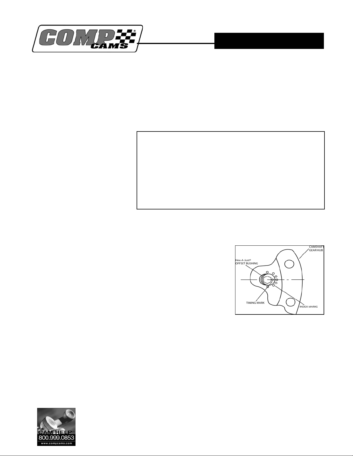
5. Insert the Timing Bushing. Insert the offset bushing (with the
Hex hole) into the slot in the camshaft sprocket hub. Rotate it with a 1/4”
Hex Wrench so that the timing mark on the bushing points away from the
center of the hub (Figure 1). The adjustable Timing Bushing is infinitely
adjustable so you can fine adjust your engine’s CAMSHAFT TIMING to EXACTLY WHERE YOU
WANT IT.
6. Mount the Camshaft Sprocket. Loop the chain over the camshaft sprocket. Align the camshaft
and crankshaft timing marks and loop the chain around the crankshaft sprocket. Lift the camshaft
sprocket into place on the camshaft, with the Thrust Bearing and Bushing in place. Be sure that the
timing mark aligns with Socket Head Cap Screws supplied. Install these bolts slightly loose.
1. 5/16” Hex Bit Socket or Hex Wrench
2. Torque Wrench
3. Hammer
4. 1/4” Hex Bit Socket or Hex Wrench
5. Sleeve to fit over crankshaft for installing crankshaft sprocket
6. Degree Wheel (optional, but recommended)
7. Assembly Lube or Camshaft Lube
8. Thread Locking compound
9. Cam button (optional, but recommended)
INSTRUCTIONS
Tools and supplies needed:
Inserting Offset Bushing
(Figure 1)
Competition Cams, Inc
3406 Democrat Rd.
Memphis, TN 38118
(901)795-2400 FAX (901)366-1807
www.compcams.com
1
Part #229
Revised 7/6/05
7. Install the Cam Button. Install the cam button using the
instructions enclosed with it.
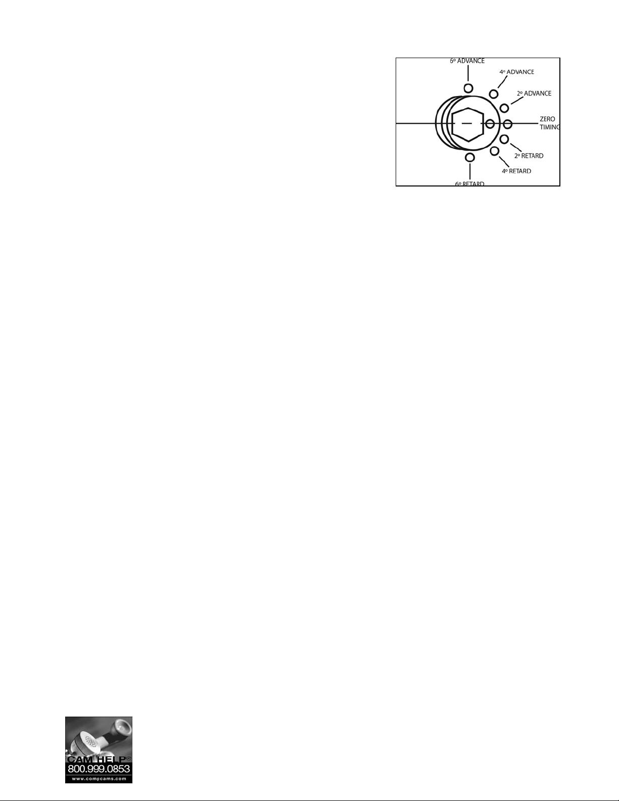
8. Adjust the Camshaft Timing. Do NOT try to turn the camshaft
with the bushing unless there is NO LOAD on the camshaft. There
must be NO VALVE SPRING PRESSURE against the camshaft or
the bushing will SPLIT. Make sure that the three camshaft bolts
are LOOSE. For a simple installation, adjust the bushing to the
desired timing setting (Figure 2). For a more accurate installation,
use a degree wheel. The degree wheel method is strongly
recommended.
Adjusting the Timing
(Figure 2)
9. Torque Loose Bolts. Remove each of the three (3) Cam Gear
mounting bolts, one at a time, and apply the Thread Locking Compound,
then torque each bolt to 300 in-lb (25 ft-lb).
10. Lubricate the Timing Set. Make sure that the engine oil has a clear path to the timing set through
the lifter valley oil drain-back holes, or through some other means. A timing set requires plenty of oil
to survive. Before installing the timing cover gasket and timing cover, pour plenty of assembly lube
over the sprockets and bearings. Assembly lube will stay on the sprockets until the engine is started.
11. Install the Timing Cover and Gasket. Install the timing cover gasket using a small amount of
gasket sealer if desired. Mount the timing cover and install the mounting bolts. Torque these bolts
as specified by the manufacturer.
Limited Warranty
Competition Cams, Inc. warrants that all of its products are free from defects in material and workmanship, and against
excessive wear for a period of (1) one year from the date of purchase. This limited warranty shall cover the original
purchaser.
Competition Cams, Inc.’s obligation under this warranty is limited to the repair or replacement of its product. To
make a warranty claim, the part must be returned within (1) one year of purchase to the address listed below, freight
prepaid. Items covered under warranty will be returned to you freight collect.
It is the responsibility of the installer to ensure that all of the components are correct before installation. We assume
no liability for any errors made in tolerances, component selection, or installation.
There is absolutely no warranty on the following:
A) Any parts used in racing applications
B) Any product that has been physically altered, improperly installed or maintained;
C) Any product used in improper applications, abused, or not used in conjunction with the proper parts.
There are no implied warranties of merchantability or fitness for a particular purpose. There are no warranties,
which extend beyond the description of the face hereof. Competition Cams, Inc. will not be responsible for incidental and
consequential damages, property damage or personal injury damages to the extent permitted by law. Where required by
law, implied warranties or merchantability and fitness are limited for a term of (1) one year from the date of original
purchase.
This warranty gives you specific legal rights and you may also have other legal rights, which vary from state to state.
Competition Cams, Inc
3406 Democrat Rd.
Memphis, TN 38118
(901)795-2400 FAX (901)366-1807
www.compcams.com
2
Part #229
Revised 7/6/05
 Loading...