

COMP Cams 31-1001 Ford Hydraulic Roller Lifter Kit User Manual
Ford Hydraulic Roller Lifter Kit
Part #31-1000 (Retro-Fit) & #31-1001
Thank you for choosing COMP Cams® products; we are proud to be your manufacturer of choice.
Please read this instruction sheet carefully before beginning installation and also take a moment to
review the included limited warranty information.
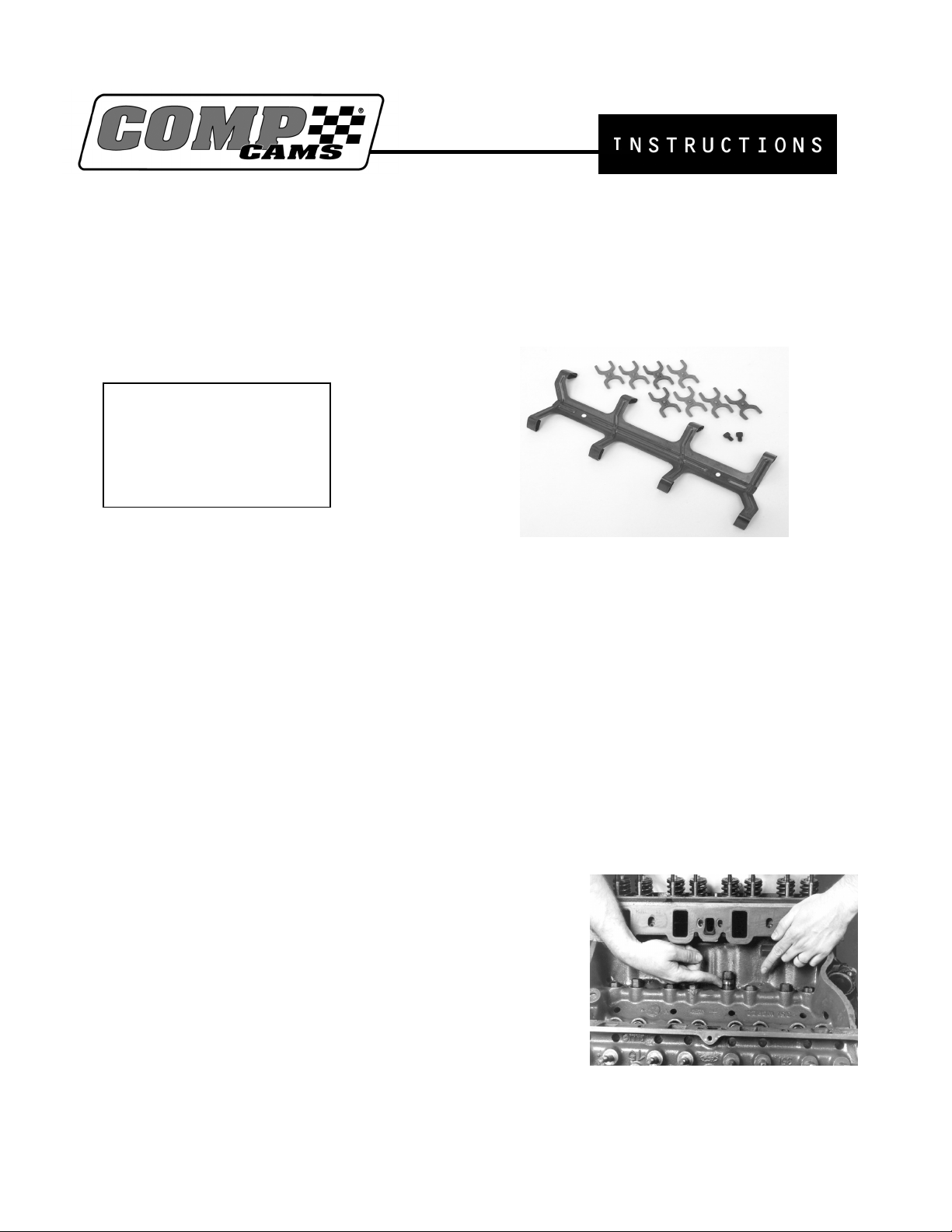
Kit Includes
• Lifter Guides (8)
• Lifter Retainer (1)
• Allen Bolts (2)
Before you Start
Please read these instructions carefully and completely before installing these products!
• This kit (Part #31-1000) is designed to allow installation of hydraulic roller cams in standard
Ford V8 engines (289, 302, 351W, 351C, 351M and 400M) not originally equipped with
hydraulic roller cams. However, it can only be used with specially designed COMP Cams®
retro-fit hydraulic roller cams with special sized base circles, or severe engine damage may
result. Also, this kit should only be used in engines with adjustable valve trains.
• This kit (Part #31-1001) is designed to allow installation of hydraulic roller lifters in standard
Ford V8 engines originally equipped with hydraulic roller cams. In order to use this kit, your
engine must have two bosses cast into the block in the lifter valley area. These bosses may or
may not be drilled and tapped for ¼”-20 bolts. If yours are not drilled and tapped then you must
be prepared to do so during this installation process.
Step 1 – Installing the Lifters
Slide the lifters (Part #851-16) into the lifter bores just like a
regular lifter, and then rotate them until the flat surfaces on the
sides of all lifters face inward toward the lifter valley. Each
lifter has two flats, one on each side. It does not matter which
flat faces the valley and which faces the cylinders. You may
encounter some difficulty in trying to install the end lifters in
each bank due to interference from an ear on each end of the
head gaskets. Gently bend this ear out of the way, install the
lifters, and then bend the ear back into place. The purpose of
this ear is to help locate the intake gasket during manifold
assembly, so do not bend or remove permanently.
Part #177
Revised 12/18/03

Step 2 – Installing the Lifter Guides
The purpose of the guides is to prevent the lifters from rotating,
therefore keeping the lifter wheels rolling over the cam lobes as
opposed to sliding. With all the flats on the lifters in line,
install one of the lifter guides over each cylinder’s pair of
lifters in the valley. They should be installed with the word
“UP” stamp into each guide facing up. It does not matter
whether the “UP” stamp is toward the front or the rear of the
block. The forks on each end of the guides should nest over the
top of the flats on either side on each lifter. Also, the lifter
guides should sit perfectly flat on the milled top surface of the
lifter bore pairs. If they do not, stop and figure out why before
proceeding. Failure to do so may result in significant engine damage.
Note: If you are using a factory hydraulic roller block and part # 31-1001, precede to Step 4.
Step 3 – Preparing the Block
Place tape over the four vent holes in the valley of the block to
prevent anything from falling through. Place the stamped steel
lifter retainer in the valley of the block with the fingers of the
retainer between the pairs of lifters and riding on the raised ball
area of the lifter guides. Use the lifter retainer in this position
as a template. Center punch the valley of the block through the
two holes, two inches from each end of the lifter retainer. Then
drill 13/64” holes no more than 3/8” (0.375”) deep. Warning:
Do not drill any deeper or you may cause damage to the cam
bearings. Be sure to drill the two holes as straight as possible.
Remove the lifter retainer. Clean up all metal shavings. Clean the freshly drilled holes using a cotton
swab lightly coated with grease. Thread the holes using ¼”-20 N.C. starter tap. Then tap again with a
bottom tap. Again, clean the threaded holes with a cotton swab lightly coated with grease. Then use a
clean cotton swab and cleaning solvent to remove the grease from the threaded holes. Once all the
metal chips have been cleaned from the valley, remove the tape from the four vent holes in the valley
of the block
.
Step 4 – Final Assembly of the Lifter Retainer
Lower the lifter retainer in place for installation, with the fingers of the retainer between the pairs of
the lifters and riding on top of the raised ball area of the lifter guides. Check the thread fit of the two
¼”-3/8 N.C. Allen bolts. Clean the threads of the Allen bolts. Put two drops of thread locker on each
bolt and tighten very lightly to approximately five foot pounds of torque.
Step 5– Final Check
Spin the engine over by hand at the crankshaft with a wrench and watch closely to movement of the
lifters. As the lifters move up and down, the lifter guides should remain perfectly flat on the tops of the
lifter bores. They should not be moved at all. If they do, the camshaft does not have the correct base
circle size to be used with these retro-fit lifters in non-hydraulic roller cam engines. Stop here and
replace the camshaft with the proper one before proceeding. Running the engine with this condition
will surely result in major engine damage. The installation of your COMP Cams® hydraulic roller
lifter kit is now complete. Refer to the camshaft installation and degreeing instructions that came with
 Loading...