

Page 1
com
atico
p
• I
• I
■
0
C
Page 2

Table of Contents
Introduction ...............................................................................................................2
Tools Required ..................................................................................................3
Electrical Power Distribution & Wire Management .........................................4
Pre-Installation Requirements ..........................................................................4
Installation Preparation .....................................................................................4
Installation Sequence........................................................................................5
Panel Support ....................................................................................................5
Load Capacities .................................................................................................6
Panel Installation ......................................................................................................7
Connecting Panels to Connectors ..........................................................................7
Connecting Panels to Panels ..................................................................................8
Panel End Cap Kit ....................................................................................................8
Panel Height Change—At Connector .....................................................................9
Panel Height Change—In-line.................................................................................10
Variable Height Filler Trim .......................................................................................11
Wall Hanger Strips ...................................................................................................11
T-Connection Installation .........................................................................................13
Power Distribution
Specifications & Installation ...................................................................................................14
Duplex Receptacles................................................................................................................. 15
Power Entry ............................................................................................................................... 15
Wiring Guide .............................................................................................................................. 15
Panel Base & Connector Base Covers.............................................................................. 16
Base End Caps ......................................................................................................................... 17
Work Surfaces
Straight .........................................................................................................................18
Corner ..........................................................................................................................19
Peninsula ..................................................................................................................................21
Transaction Surface ..............................................................................................................22
Pencil Drawer .......................................................................................................................... 22
Overhead Storage
Shelf ...........................................................................................................................................23
Flipper Door ............................................................................................................................. 24
Tack Board/Marker Board ................................................................................................... 24
Task Light ................................................................................................................................. 25
Storage Pedestals.......................................................................................................................... 25
AO1 / AO2
/ AO2 PolyPanells
2
Page 3

Introduction
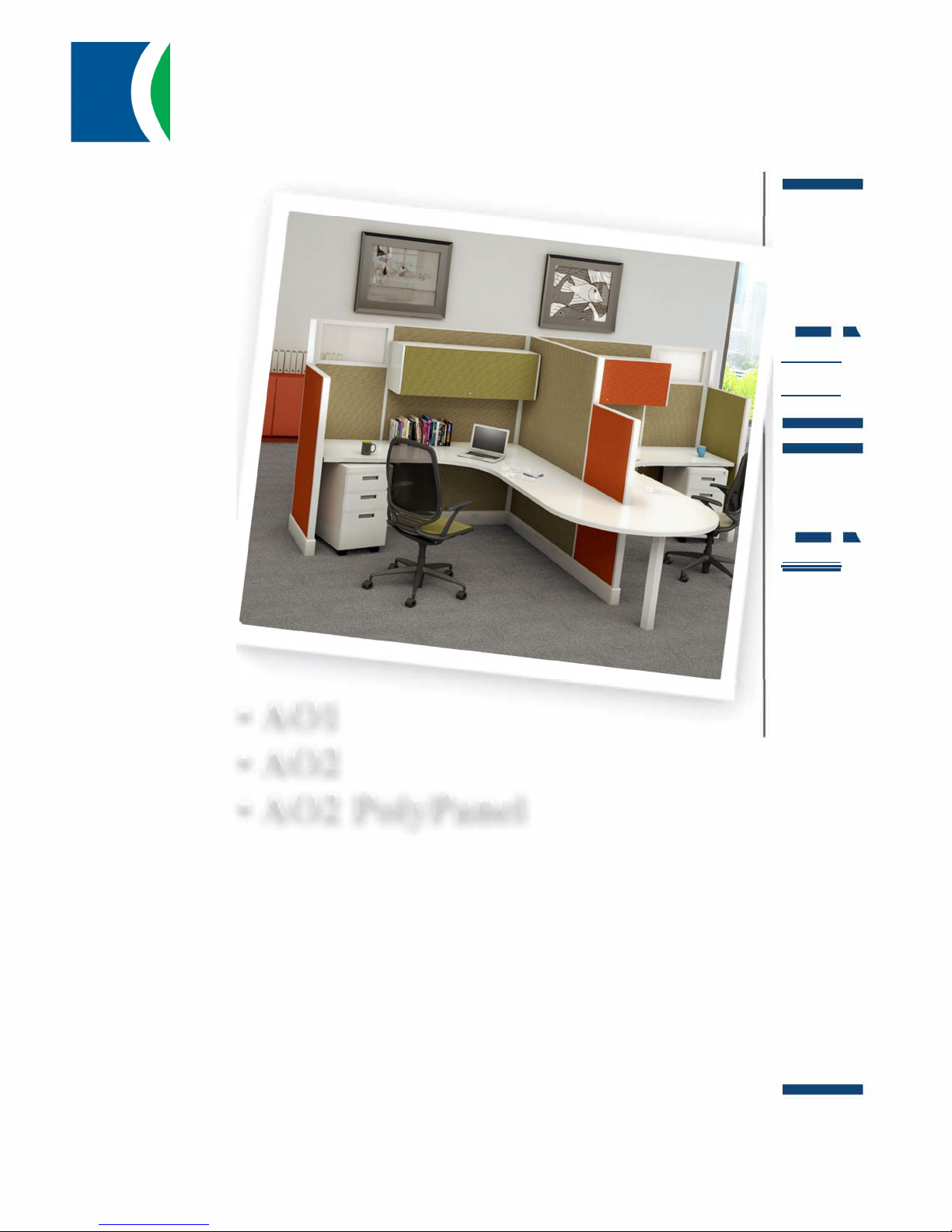
These instructions provide the necessary information to safely install Compatico’s following products:
• AO1
• AO2
• AO2 PolyPanel
AO1/AO2/AO2 PolyPanel is a time-tested office partition furniture sys
tem that includes a
comprehensive vocabulary of panels, power/cabling management, work and storage
components as well as accessories. These products also offer the distinction of family of
modular furniture designed to provide a broad range of solutions for both open plan and private
office requirements. AO1/AO2/AO2 PolyPanel is designed to provide inordinate flexibility and
cost savings with the added ability to route, manage and store cables in accordance with the
latest telecommunications industry standards.
The characteristics of the system require panel arrangements and panel supports as outlined in this
manual for a safe and secure installation. Rearrangements and additions to an installation must to
the same stability and installation guidelines to ensure continued safe use. Compatico shall not be
liable for product that is used or altered in any other way.
WARNING: Failure to follow these instructions can result in personal injury or product damage or
both.
Tools Required
Many products are shipped assembled at the factory and need only to be installed. Some
products are shipped in subassemblies requiring field assembly during installation. The
following are tools necessary to properly install Compatico AO1/AO2/AO2 PolyPanel products.
• ” Allen Wrench
• #2 and #3 Philips Screwdriver/bits
• 25’ – 30’ Tape Measure
• Plastic/Rubber Mallet
Slotted Screwdriver
•
• 6” long Philips Extension Bit (for pencil drawer bearers)
• 9”-long or longer Magnetic ‘Torpedo’ Level
• Utility Razor Knif
e
The following tools will speed-up larger installations or be handy in special circumstances.
• 12v – 18v Drill/Driver (with spare batteries and charger)
• Set of Drill Bits & Screw Bits
• ” Ratchet Allen Wrenc
• Chalk Line and/or 2” Masking Tape (to locate/mark panel run starts)
• 4’ Carpenter’s Bubble Level
• Hack Saw or Power Reciprocating Saw with Metal Blades
Hammer
•
• Pliers
• 250-lb capacity Wonder™ Bar (pry bar)
• Aviator/Tin Snips (yellow handle)
• Continuity/Electrical Tester
• Panel Skates (for 10 work stations or more)
• Dollies & Panel Carts (for 10 work stations or more)
• Laser Leveler Device (for 10 work stations or more)
AO1 / AO2 / AO2 PolyPanells
h
3
Page 4

Electrical Power Distribution and Wire Management
Electrical power distribution components are modular and allow complete integration with the
AO1/AO2-series furniture system products. Please read and follow this information carefully before
proceeding with any furniture installation requiring electrical components.
WARNING: Disconnect power before servicing any component. Failure to do so can cause
rical shock and personal injury or property damage.
elect
Electrical power system is:
• UL-Listed/CSA-Certified and labeled
• Constructed with shielded conduit to provide an effective built-in EMF barrier
• Eight-wire, four-circuit design
• 15-amp capacity
• Three general-purpose circuits
• One dedicated circuit with isolated ground
Pre-Installation Requirements
The electrical power distribution system is an eight-wire/four-circuit modular system that can supply up to four
circuits with single-phase or three-phase power. Each circuit is rated 125v/15-amps and can supply a maximum
of 13 receptacles.
1. Before starting the electrical component installation, be sure to coordinate the layout with the building
wer supply sources.
po
2. Connection of the electrical components to the building electrical supply must be performed by a
qualified electrician.
Installation Preparation
Take care examining contents of each box making sure small packages within boxes are not
overlooked.
1. Sort and stage all items:
•
Panels
•
Connectors and End Trim
•
Wire Management Raceway (AO1 only)
•
Power Components
•
Wall Tracks
•
Cable Poles
•
Work Surfaces and Support Components
•
Overhead and File Pedestal Storage Components
•
Pencil Drawers and Accessories
2.
Review building drawings closely to determine exact location of panel runs.
3. Mark floors with chalk lines and/or tape to mark starting points and openings.
4. Start at high point of the floor, if possible.
AO1 / AO2 / AO2 PolyPanells
4
Page 5
Installation Sequence
Compatico recommends the following sequence to assemble AO1/AO2/AO2 PolyPanel product:
Install Panels and Connectors (with Wire Management/Power kits—AO1 only); install
1.
Panel End Trim at ends of panel runs.
Install Power Distribution and In-feeds (not wired to power supply).
2.
Install Overhead Storage and Task Lights.
3.
Install Work Surfaces and Floor-supported/hanging Pedestals and/or File Centers.
4.
Install Tack Boards & Marker Boards.
5.
Install Accessories.
6.
Wipe down furniture.
7.
Panel Support
These panel installation instructions are written for user safety. Please follow them at time of
planning and specification, initial installation and any addition or reconfiguration.
Definition and Application:
1. Panel runs are any two or more panels connected in a straight line.
2. Panels mounted at right angles to panel runs are called support panels. Height of
support panels must be equal to the height of the panels in a run or
• 62”/67”h for 80”/85”h panels
• 48”/53”h for 62”/67”h panels
• 42”/47”h for 48”/53”h panels
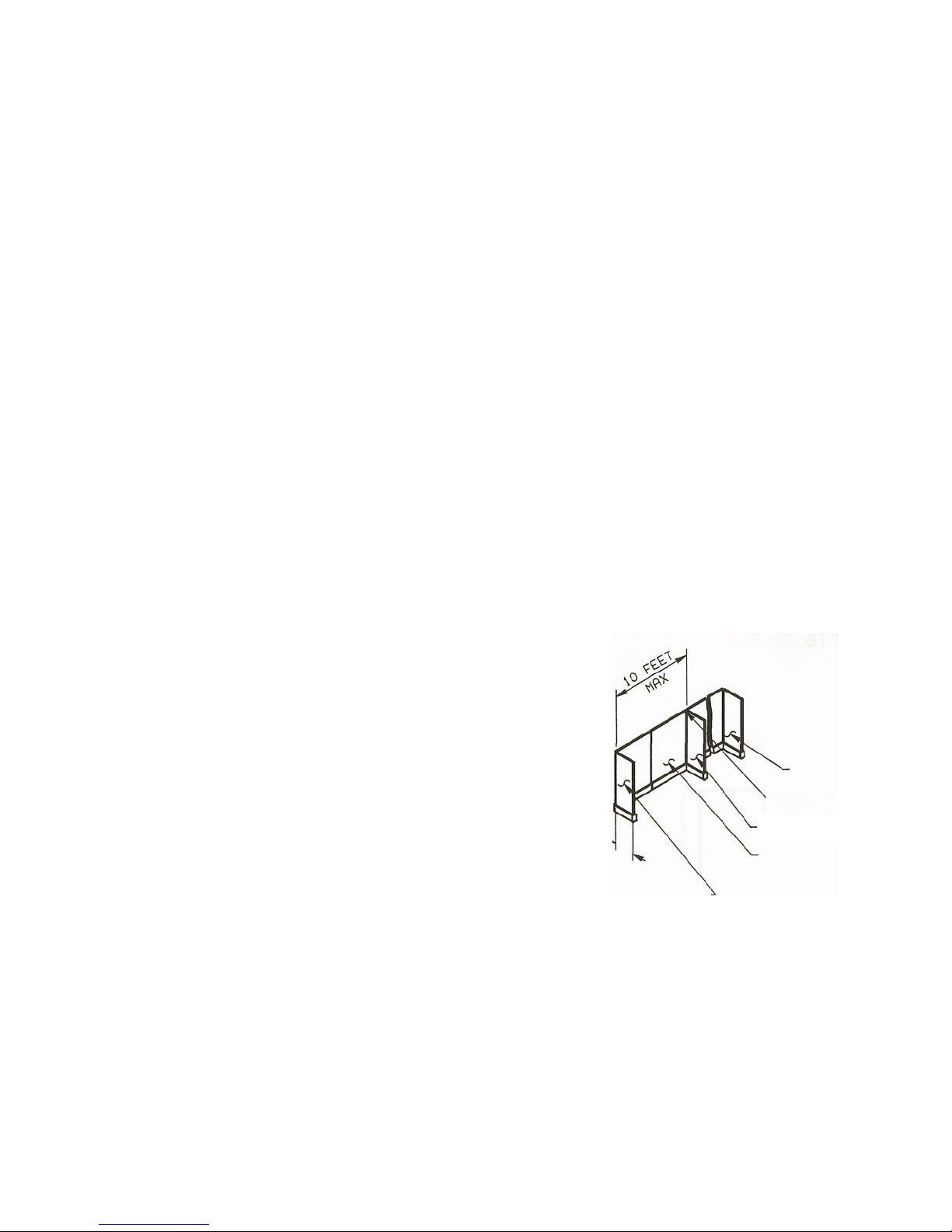
3. All support panels must be at right angles to run panels and on one or both sides of run
panels, depending on the panel loading, and spaced no more than ten feet apart.
• Panel runs loaded on one side with
overhead storage and/or work surfaces
must have support panels on the load
ed
side with 36” minimum width at the
beginning and ending panels and at
intervals not to exceed ten feet; for
Acoustical, Glazed and Open-Frame
panels, must not exceed eight feet.
36” min
Support
panel
Support panel
Panel Connector Joint
Support panel
Load-bearing side of panel
AO1 / AO2 / AO2 PolyPanells
5
Page 6
•
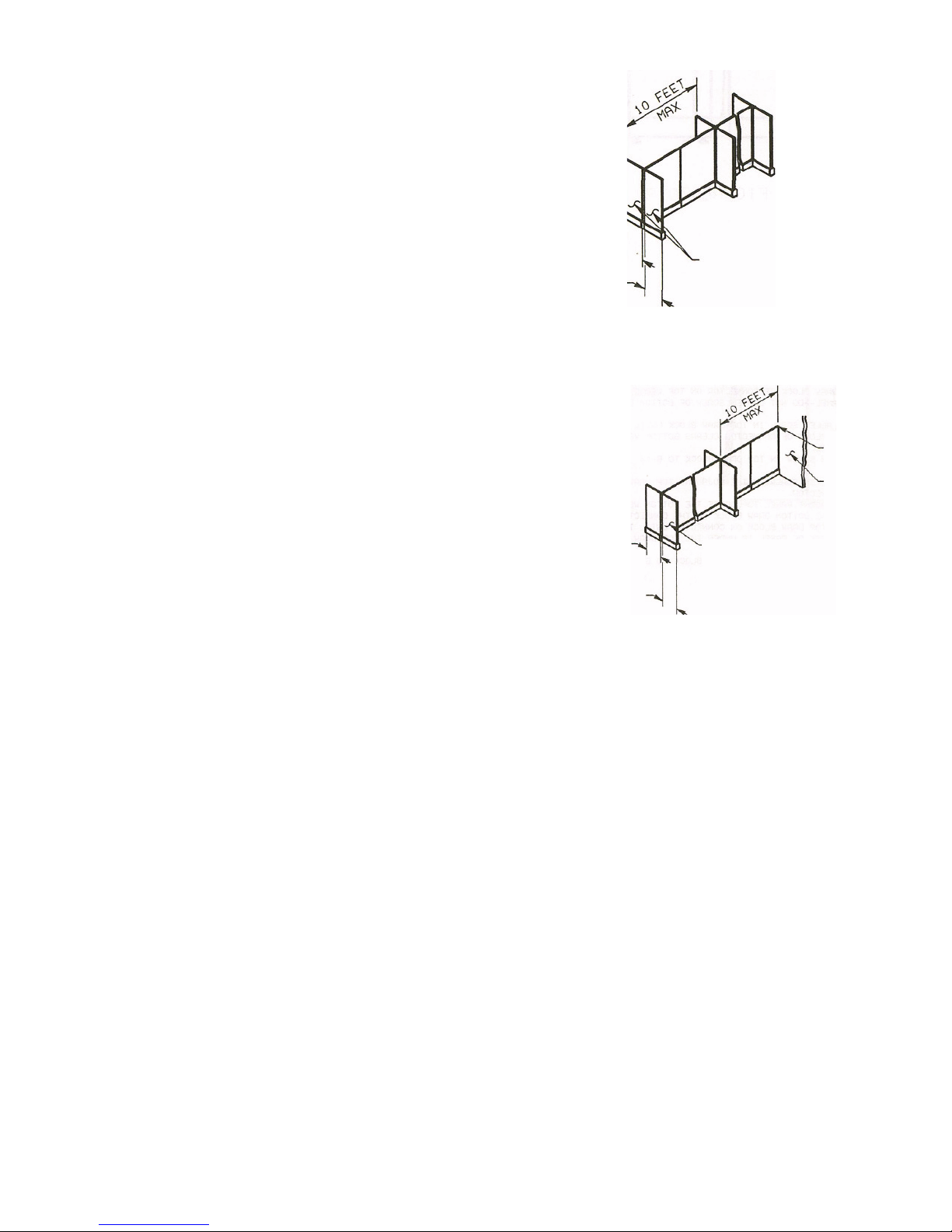
Panel runs loaded on both sides with
overhead storage and/or work surfaces
must have support panels on both sides of
the run. Support panel width must
correspond to the depth of the deepest
component mounted to the panel run on
that side of the run at the beginning an
ending panels and at intervals not to exceed
ten feet; for Acoustical, Glazed and OpenFrame panels, must not exceed eight feet.
d
12” min,
both
sides Minimum support panel width must match
Support panels
or exceed depth of dee pest component
that
side of the panel run.
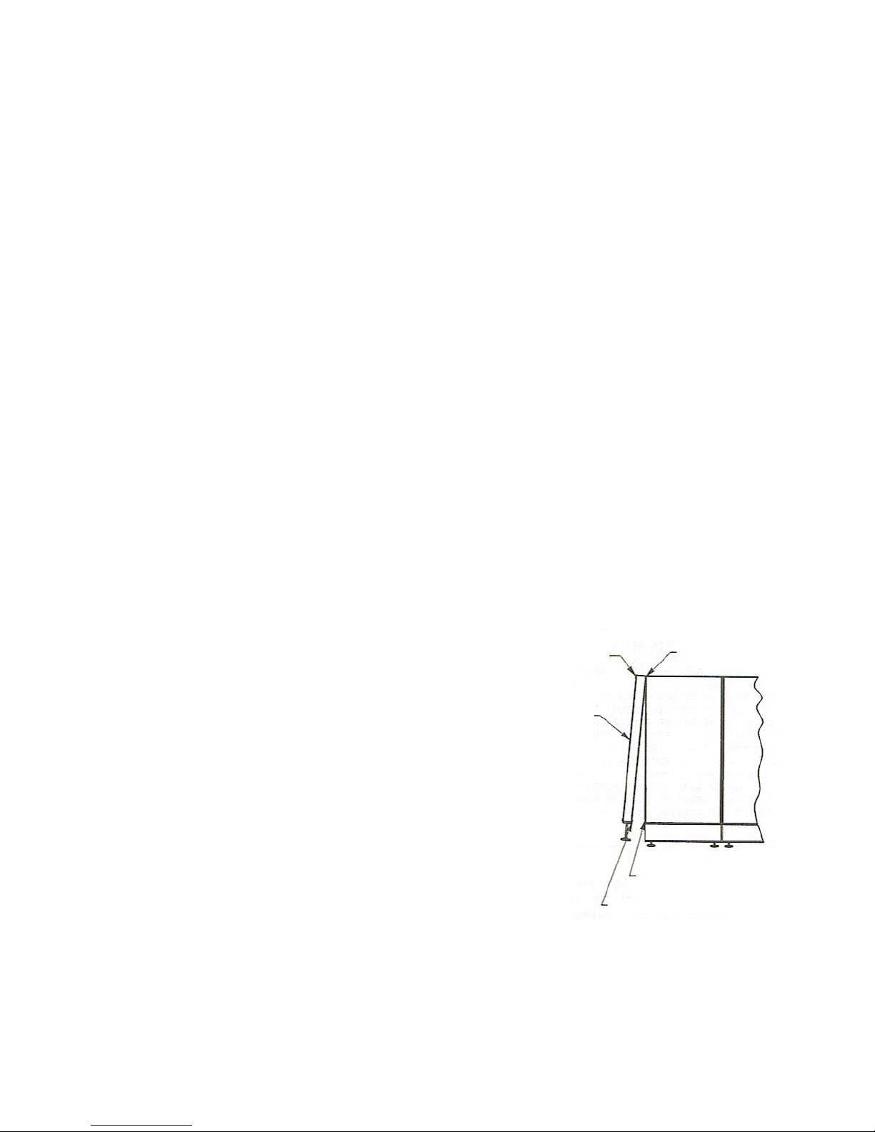
4. T-Connectors are used to connect panel runs to eit
tructural wall or building column or along a mid-point of
s
her a
another panel.
• A structural wall is a load-bearing wall constructed
of poured concrete, cement blocks or composit
rd attached to metal or wood studs.
boa
e
• Wood studs must be a nominal 2” x 4” size.
• Metal studs must be 20-ga. “c”-channel, center-to-
center dimension not to exceed 24” and be less
than 14’ tall, restrained at both ceiling and floor.
Width as
required
by loading
conditions
Support
panel
Load Capacities
Compatico will not, under any circumstances, guarantee or assume responsibility for loading
performance beyond the basic individual component capacities given below:
• Hanging work surfaces, 60” or less wide:
o 250 lbs, 18” deep
o
200 lbs, 24” d
200 lbs, 30” d
o
• Hanging work surfaces, 66” – 96” wide:
o 250 lbs, 24” deep (with three work surface supports)
o 250 lbs, 30” deep (with four work surface supports)
• Shelves: 150 lbs
• Hanging storage pedestal (Box/File): 25 lbs
• Pencil drawers: 5 lbs
eep
eep
“T” Connect or
Structural
wall
Load capacities as listed above for work surfaces include the total load of fully loaded hanging
components attached to the underside of the work surface plus the load placed on the top of the
work surface.
WARNING: Failure to observe the recommended practices such as loading beyond stated
capacities can result in unsafe usage conditions and product damage or personal injury or both.
Before storage components and accessories are installed on panels, be sure to level panels
and adjust each panel glide to make firm contact with the floor to maintain panel alignment and
to distribute panel load uniformly to floor. Check panel stability after installation is complete and
furniture components are attached; adjust any panel glides as may be necessary.
AO1 / AO2
/ AO2 PolyPanells
6
Page 7
Panel Installation
Important:
• Start at a 2-way, 3-way or 4-way connector junction so that the initial panels, once
connected, will remain free-standing; then build from there according to your layout print.
Construct this connector junction at a locatable point from the layout print on the
installation floor. Use chalk line or masking tape to mark the starting location.
• To connect adjacent panels of equal height, use a rod & block connector.
• Use a two-way 180˚ connector for equal or unequal height panels.
• Two-way 90˚ , three-way and four-way corner connectors provide the panel-to-panel
connection necessary in either of the following situations:
o Adjacent panels are unequal in height
o Adjacent panels are at a 90˚ angle to each other and of either equal or unequal height.
o A group of three or four equal- or unequal-height panels at 90˚ from a common point.
• At each connector junction where there will be a panel height change, refer to Connector
Change-of-Height procedure.
• Be sure to level panels before installing components.
Connecting Panels to Connectors:
Equal Height Panels:
Note: Wherever your furniture plan calls for transaction counters mounted to panels, please
review the section “Transaction Counter Installation” before connecting the panels beneath.
1. Place top draw block of connector on the top wedge block of the first panel.
2. Loosen screw in top draw block of connector, with ” Allen wrench or hex bit, until the
bottom draw block of the connector clears the panel’s bottom wedge block.
3. Tighten the same connector draw block
screw until panel and connector are
securely attached.
4. Loosen an/the adjacent top connector
Top draw blocks
Top wedge block
draw block screw.
5. Move the adjacent panel to locate the
bottom wedge block over the bottom draw
block on the connector.
6. Lift up the loosened top draw block on the
connector and position the panels top
Rigid connector:
2-way 90˚
2-way 180˚
3-way
wedge block adjacent to the connectors
top wedge block, drop connector draw
block over the two adjacent wedge blocks.
7. Tighten connector draw block screw until
panel and connector are securely
attached.
8. Repeat steps 2 through 7 for any
additional connector draw blocks (3-way
and 4-way connectors).
Bottom wedge block
Bottom draw blocks
AO1 / AO2
/ AO2 PolyPanells
7
Page 8
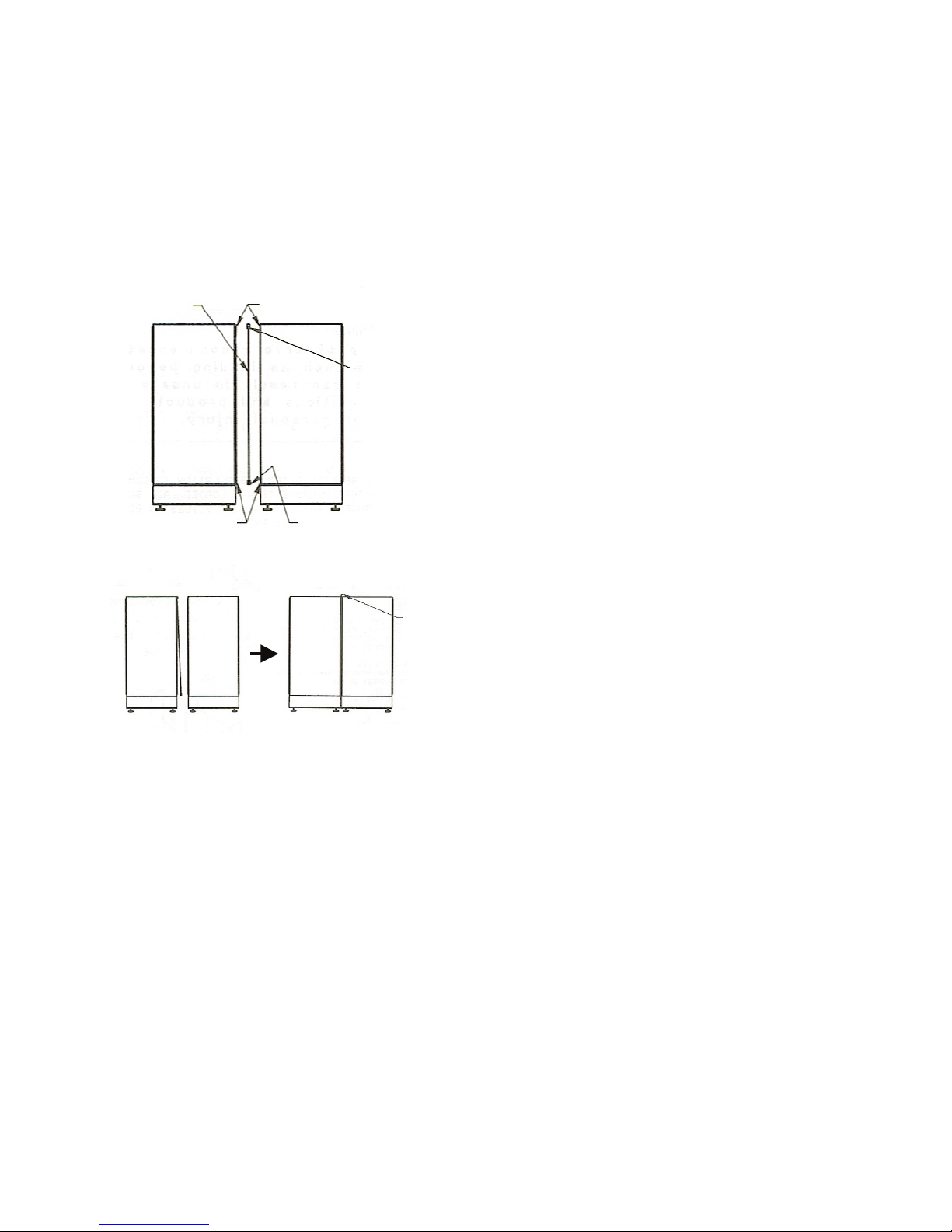
Connecting Panels to Panels:
A Rod & Block Panel Connector is required to connect two panels in a straight line.
Note: Wherever your furniture plan calls for transaction counters mounted to panels, please
review the section “Transaction Counter Installation” before connecting the panels beneath.
Equal-height Panels:
1. Place top draw block of connector on
Panel connector
Top wedge blocks
top of wedge block of first panel.
2. Loosen the Allen screw in the top
draw block of the connector rod until
the bottom draw block of connector
Top draw block
rod clears bottom wedge block of first
panel.
3. Move and position adjoining panel’s
bottom wedge block adjacent to first
panel’s bottom wedge block within
open half of connector rods bottom
draw block. Then raise the connector
rods draw block and position the
Bottom draw blockBottom wedge blocks
adjoining panels top wedge block next
to the first panels top wedge block,
under the open half of the connector
rods top draw block.
4. Tighten connector rods Allen screw
until panels are securely attached.
” Allen
wrench
5. After assembly of a run of panels,
adjust panel glides in bottom of all
panels to level panel run and to put
equal weight on all panel glides.
Panel End Cap Kit
Use to trim the exposed hardware on the vertical end of a panel at the end of a panel run.
Note: Wherever your furniture plan calls for transaction counters mounted to panels, please
review the section “Transaction Counter Installation” before connecting the panels beneath.
1. Place draw block of the End Cap over the top wedge block of the panel.
2. Loosen ” hex/allen screw at top of End Cap until bottom draw block clears bottom wedge block
of the panel.
3. Tighten hex/allen screw until End Cap is fastened firmly to the panel.
Note: Do not over tighten top Allen screw; it may cause Panel End Cap to bow.
AO1 / AO2
/ AO2 PolyPanells
8
Page 9
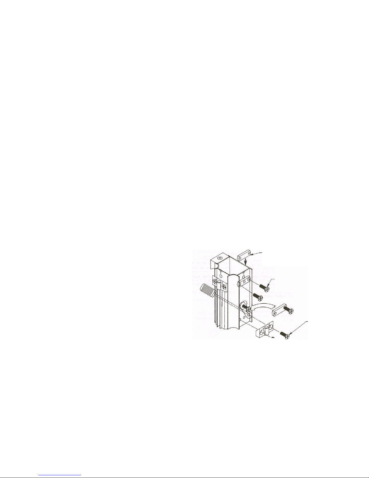
Panel Height Change
At a Connector
Note: Wherever your furniture plan calls for transaction counters mounted to panels, please
review the section “Transaction Counter Installation” before connecting the panels beneath.
Follow the instructions below for changing the connector wedge block position on any 2-way 90˚, 2-way
180˚, 3-way or 4-way connector to attach a panel of lower height.
1. Lay connector on a flat, protective surface.
2. Remove connector Top Draw Block(s) to reveal top cap release port.
3. With a screwdriver, press both top cap extension tabs, as shown at right, while pulling on top cap
to release it.
4. Remove connector wedge block (Top Draw Block and Top Wedge Block) by removing both
wedge block screws. Remove the threaded nut plate that has dropped after removing the screws
by tipping the connector so that it slides out either end.
5. Remove connector filler strip from the side to be adjusted; remove from bottom end first by prying
or pulling end away. Filler strip is held in place with double-faced adhesive tape.
6. Install wedge block and threaded nut plate removed from top location to new height desired.
• Begin by threading a screw into the threaded nut plate, making sure the raised ridge
around threads faces screw head; this helps to properly locate the threaded plate.
• Position one end of the threaded plate, as shown, through the access hole above the
wedge block screw holes into place. While holding its position, place wedge block into
place. Insert screw through wedge block and connector; do not tighten completely.
• Remove wedge block screw used to position threaded nut plate. Use inserted screw to
align nut plate into position. You may
need to tighten or loosen the screw
for better positioning control and/or
hold connector for gravity to position
nut plate. Once in place, finger-start a
screw through the wedge block and
connector into the nut plate.
Threaded Nut Plate
-20 x ”
Pan Head Screw
Note: the hole in the adjacent or opposite side of
the connector can be used to insert a screwdriver
to hold the threaded nut plate in position for
installing wedge block screws.
7. Cut filler strip at bottom end and install to fit between top and bottom wedge blocks.
8. Reattach the top draw block to the connector wedge block and replace top cap.
AO1 / AO2
/ AO2 PolyPanells
Top Wedge
Block Screws
9
Page 10
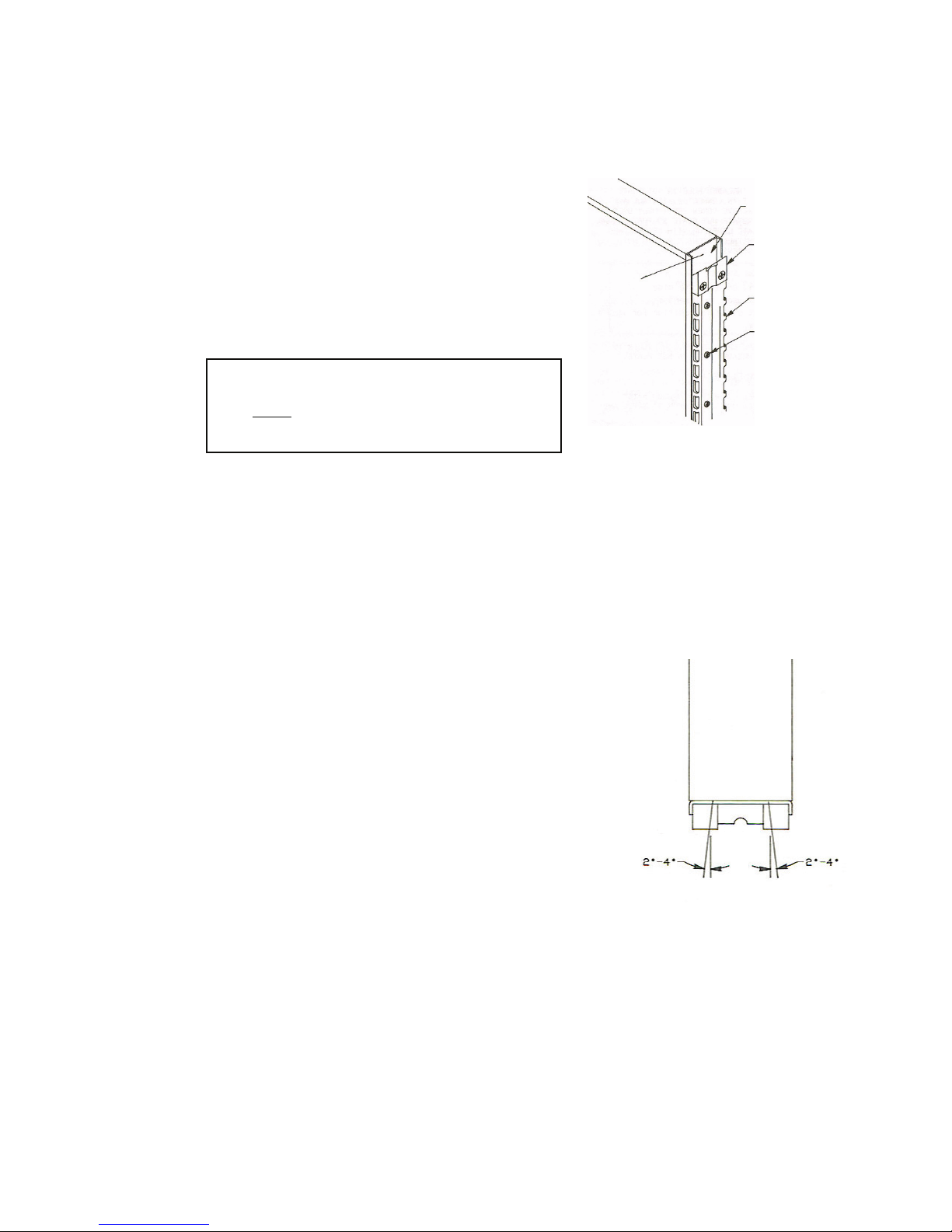
Panel Height Change
Panel-to-Panel, inline
Follow the instructions below for changing the wedge block position
on a panel end to connect to it a panel of lower height.
1. Remove both top wedge block screws and wedge block.
2. Remove hanger frame screws and hanger frame.
3. Determine the length to cut off from the top (“CC” stamped
at end) portion of the hanger frame by subtracting the
nominal height of the shorter panel from the nominal height
of the taller panel.
For example:
67” Taller panel nominal height
47
–
” Shorter panel nominal height
Amount to be removed from top
20”
4. Use hacksaw or power reciprocating saw to cut hanger frame; be sure to cut squarely. Discard top
portion of hanger frame.
5. Reinstall hanger frame and tighten screws; be sure to evenly align panel shell side-to-side.
6. Position top wedge block in new position, lowered the same distance calculated in step 3 above.
Scribe a mark at the center point of each screw hole in the wedge block.
7. Remove hanger frame, bottom wedge block, and panel shell.
8. At each scribed mark, stamp a starting dimple using a starting punch or nail. Also stamp one
between the two, inline with the two. At each of the three marks, drill a 5/16” hole through the panel
shell.
9. Reinstall panel shell, bottom wedge block and hanger frame; be
sure to evenly align panel shell side-to-side. Tighten all screws.
10. Position top wedge block in new position, lowered the same
distance calculated in step 3 above. Scribe a mark at the center
point of each screw hole in the panel frame. Remove wedge
block.
11. Drill a 3/16” hole, at a 2˚ -- 4˚ angle, through the frame rail at the
two screw locations (the centered hole is a relief for the boss on
the back of the wedge block).
Panel Shell
Top Wedge Block
Hanger Frame
Hanger Frame
Screws
Important Note: Holes must be drilled at a 2˚ -- 4˚ angle from the
panel face; failure to do so could allow drill or wedge block screw
to damage face of panel.
12. Position top wedge block in new position and attach with two wedge block screws.
13. Attach top of panel shell to panel frame through any hanger frame screw hole near top with a flathead drywall screw. Screw head must be large enough to hold panel shell down without going
through and without being raised to hamper attachment of variable height filler trim.
AO1 / AO2
/ AO2 PolyPanells
10
Page 11
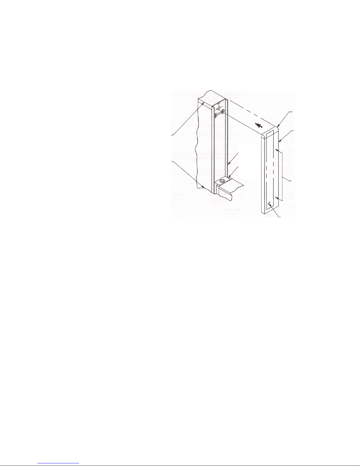
Variable Height Filler Trim
The 48” trim piece is designed to provide up to two pieces of trim for use on connectors with panels of
unequal height or two panels in line of unequal height as described above. Each end is profiled to serve as
a top, finished end.
1. Filler trim must be cut to
required length. Measure the
distance between the top of
the panel/connector and the
top of the top draw block of
the lower panel. Then
measure same distance from
one end of the trim piece and
scribe a line across the face
at that point.
2. Use hacksaw or power miter
saw; be sure to cut squarely.
Top Cap
Connector
Panel
Shell
Draw
Block
Profiled End
Filler Trim
Note: Do not discard other end;
it may also be used as a filler
trim in many cases.
Press Firmly
3. Clean the area to be
trimmed; make sure it is dry
before positioning the filler.
4. Remove paper backer from
Remove paper backer
From adhesive tape
on back
adhesive tape on back side
of filler. Position filler trim and press firmly into position. Make sure profiled end of filler trim is at top
and positioned flush with top of connector or panel top cap.
Wall Hanger Strips
Note: Wall hanger strips must be used only on a structural wall constructed in either of the following
manner, as a minimum:
•
Composite Board (drywall) over Wood or Metal Stud: Drywall must be 5/8” minimum, on 2” x 4” studs
minimum, 24”on-center maximum; 14’ height maximum, retained at both floor and ceiling. Metal studs
must be “C”-channel, 20-ga minimum thickness. Drywall must be attached by industry standards,
minimum; ideally it should include appropriate adhesive bead on each stud, the full length of the stud.
•
Poured cement wall
•
Cement block wall
cceptable fastener recommendations:
A
•
Into drywall on studs:
o
3/16” hollow wall fastener or 3/16” wall toggle & bolt with #8 flat head machine screw located 29”
and 60” from floor, minimum; other screw locations can utilize 1/8” fastener/wall toggle with #8
flat head machine screw.
o
Directly into wood stud: #8 x 2 ” flat head drywall or sheet metal screw.
o
Directly into metal stud: #8 x 2 ” flat head sheet metal screw.
AO1 / AO2
/ AO2 PolyPanells
11
Page 12
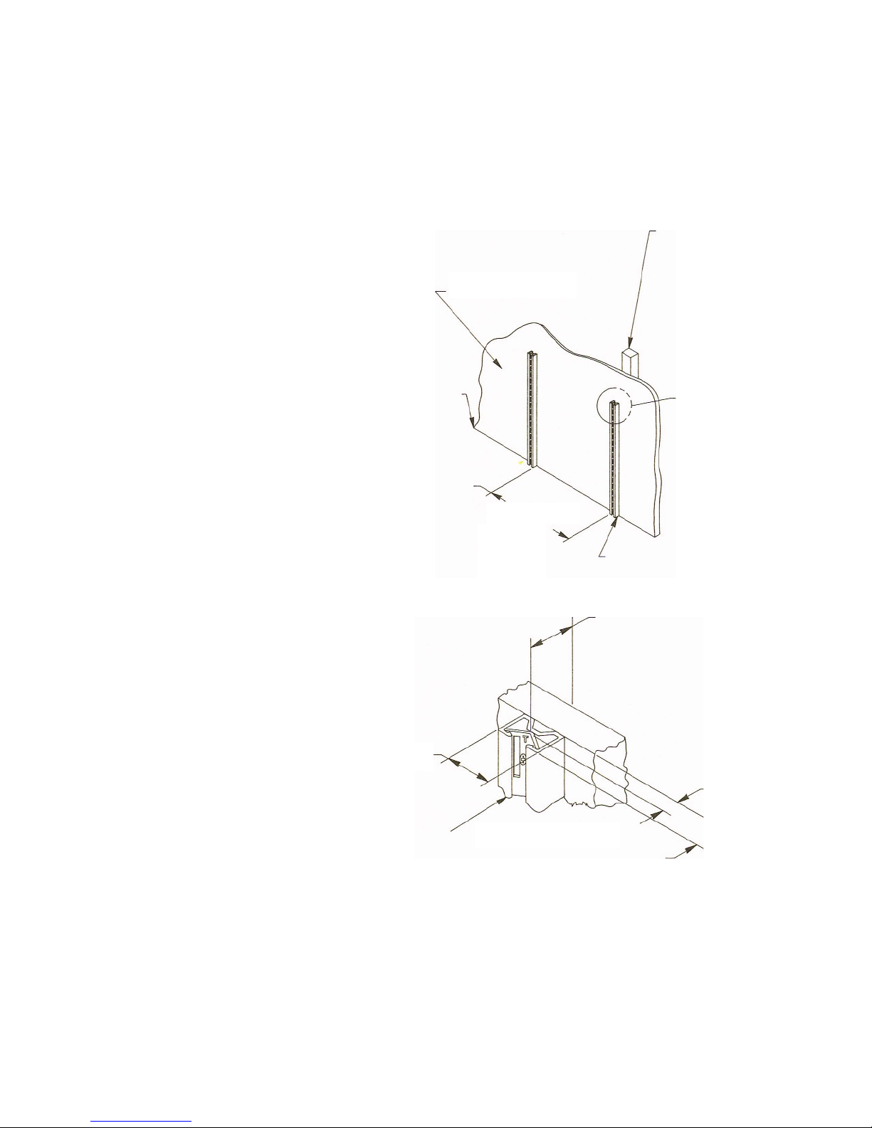
•
Into concrete, cement block or brick:
o
#8 x 1 ” flat head sheet metal screw with screw anchor.
o
3/16” x 1 ” Tapcon™ or other brand concrete anchor screw. Must be used with recommended
(
5/32”) masonry drill bit for pilot hole.
Note: Refer to fastener manufacturer’s specifications and recommendations for application, load rating and pilot
ole size. It is the installer’s responsibility to determine and select the most appropriate fastener. Compatico does
h
not assume any liability for their use.
Warning!: Failure to properly attach
wall hanger strips to a structural wall
and, where possible, to rest wall
hanger strips directly on the floor
Structural Wall
Mount wall strips at
studs where possible.
Mount wall strips only
to walls fastened to
the building structure
at the ceiling as well
as the floor.
may cause dislodgement of wall strip
and/or attached components causing
personal injury and/or property
damage.
Floor
Location and installation:
See detail “A”
Note: Wall hanger strip must be
secured to wall with appropriate
fastener every 6”.
1. Position the first wall hanger
enter-to-Center spacing:
strip at the requir
l
ocation, per furniture layout
drawing. Note that the en
w
ith the hole located closest
ed
d
to the end is the top. Attach
at top with fastener.
2. Use a level to ‘plumb’ wa
nger strip; mark hole
ha
locations on wall throug
hol
es in wall hanger strip.
ll
h
3. Drill holes, at each marking, in
C
Nominal component width,
e.g., 24”, 30”, 36”, 42”,
48” or 60”
Set bottom of wall strip
directly to floor, where
possible, for maximum
load support.
Allow for wall hanger th ickness and wall
thickness when determining fastener
length. Fasteners to be secured every 6”.
wall according to fastener
manufacturer’s
recommendation.
4. Insert fastener and complete
attachment of wall hanger strip.
5. Measure or use a spacer to
1”
locate and mark the next wall
hanger strip location.
6.
Repeat steps 2 –5 for
3/8”
remainder of wall hanger strips.
Wall Hanger Strip
elpful Hints:
H
•
Spacers may be used to
Detail “A”
21/32”
position subsequent, sequential wall strips. Cut spacers to 1” less than nominal component dimension +/1/32”, e.g., 47” (48” -1”) +/- 1/32”. Be sure to keep ends square.
•
Installers are responsible to install wall strips at a uniform height and level relative to one another. Often,
if a drop ceiling is present, their perimeter track has been installed with a laser level. Because floor levels
vary, especially cement floors, the ceiling tile track may be a better reference for locating wall strip’s
vertical position. Installer must determine best method for keeping wall strips level because their location
is critical to the subsequent outcome of the furniture installation
.
AO1 / AO2
/ AO2 PolyPanells
12
Page 13
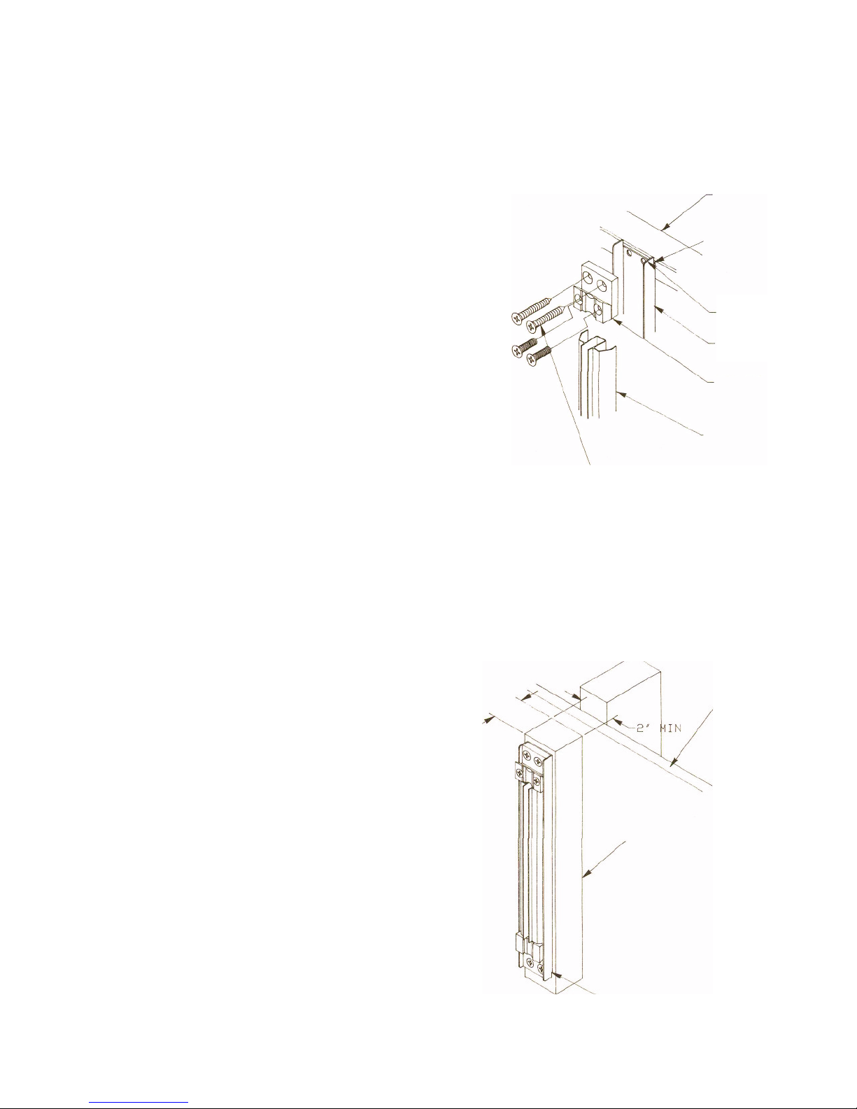
“T” Connection Installation
Use to connect a panel at a right angle to a structural wall or to another, non-steel frame, panel of
the same height.
Notice: It is the installer’s responsibility to select and install
the proper fasteners in the structural wall or panel frame.
Compatico does not assume liability for their use.
For attachment to all panels, except tubular steel frame:
1. Position the T-Connector channel at the desired
location, flush with top of panel and parallel to its
vertical edges, with notch up for clearance of panels
top cap.
2. Use holes in channel for template, bore 3/16”
diameter hole 1 ” deep into panel frame; two at the
top, two at the bottom.
3. Securely fasten wedge blocks and channel to panel
surface with #14 X 1 ” long Sheet Metal Screws.
4. Remove paper cover from adhesive strip on back of
filler strip and position filler in channel, between
wedge blocks, and press firmly in place.
5. Assemble panel to T-Connector with a standard
” long
#14 X 1
Sheet Metal Screws
panel connector.
For attachment to structural wall:
N
ote: Structural wall should be constructed in either of the following manners, as a minimum:
•
Composite Board (drywall) over Wood or Metal Stud: Drywall must be 5/8” minimum, on 2” x 4” studs
minimum, 24”on-center maximum; 14’ height maximum, retained at both floor and ceiling. Metal studs
must be “C”-channel, 20-ga minimum thickness. Drywall must be attached by industry standards,
minimum; ideally it should include appropriate adhesive bead on each stud, the full length of the stud.
•
Poured cement wall
•
Cement block wall
op Cap
T
Notch
Flush
Channel
Top (small)
Wedge Block
Filler Strip
1.
Select a wood furring strip, straight
and sound, with minimum cross
section dimensions of 1 ” X 2”. T
length must match the nominal height
of the T-Connection
2.
Bevel or plane the back of the furring
.
strip so that face of furring strip will be
plumb.
3. Select appropriate fastener for type of
structural wall and mount the furri
ip to the structural wall
str
perpendicular and resting on the floor.
4. Lo
cate channel vertically, with notch
at bottom.
5. Follow steps 2 – 5 above to attach T-
Connector to furring strip.
AO1 / AO2
/ AO2 PolyPanells
Structural
1
” Minimum
Wall
he
Furring Strip
ng
,
Notch
13
Page 14
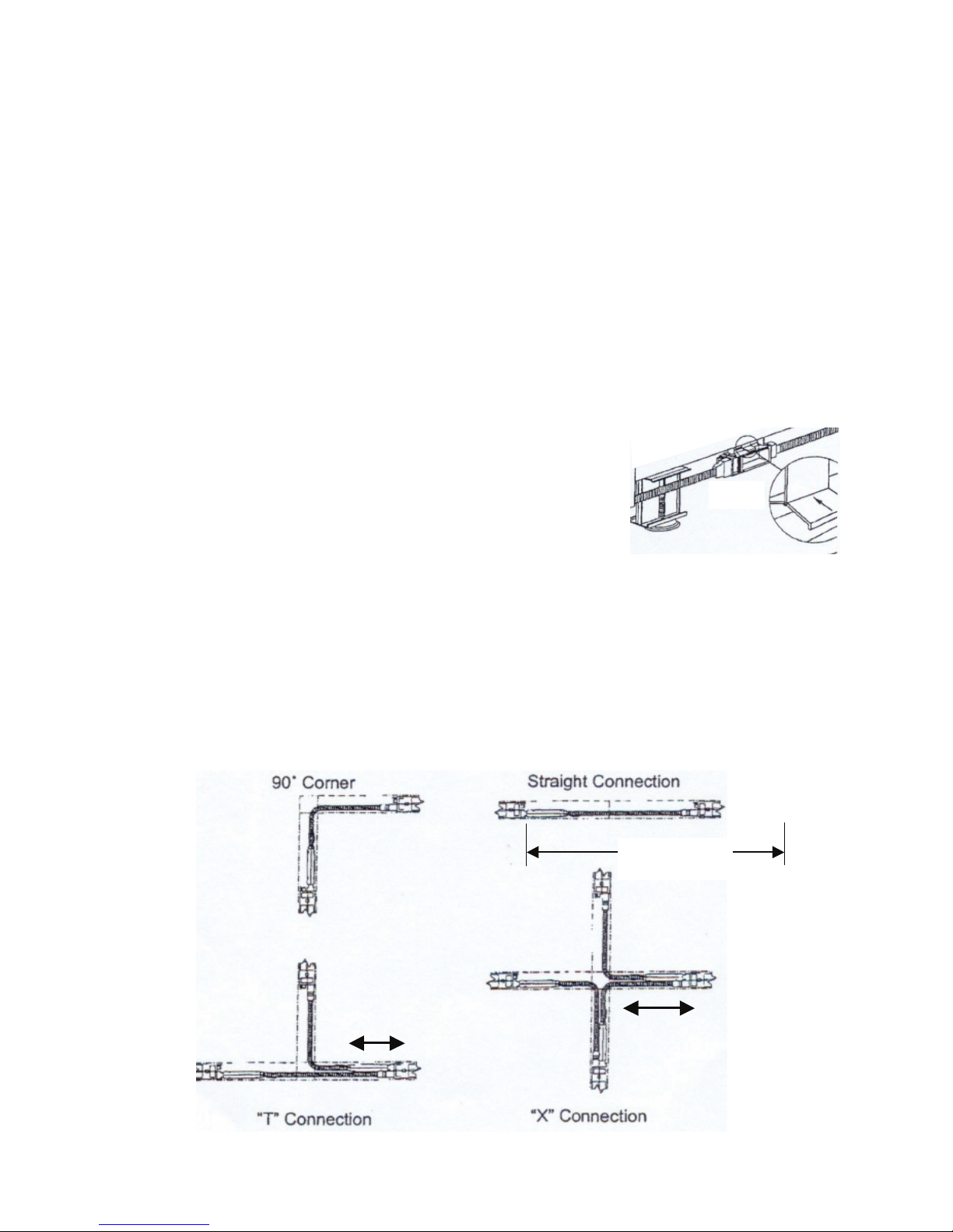
Power Distribution
Compatico eight-wire/four-circuit power system specifications:
o UL-Listed/CSA-Certified and
labeled
o Constructed with shielded conduit
to provide an effective built-in
o Eight-wire, four-circuit design
o 15-amp capacity
o Three general-purpose circuits
o One dedicated circuit with isolated ground
EMF barrier
Compatico AO2 and AO2 PolyPanel series panels specified with power come with the power
distribution harness attached to the panel.
To connect power distribution harnesses and/or pass-thru cables together or between one or
another
1. The flexible conduit/connector is polarized so that it can only connect to the appropriate end
of a pass-thru cable or to the male terminals on the power
block of a power distribution harness (one terminal on the
male end of the connector is crowned).
If the power distribution harness needs to be removed, remove
the power block from mounting bracket, use a small prybar or
flat-blade screwdriver to press down plastic tab of power block
on either side of the mounting bracket center tab until you can
push the power block through.
2. Simply make sure the polarized ends are appropriately matched and press together. You
should hear an audible ‘click’ when they have made a proper connection. If not, please
examine carefully to make sure the two are fully connected by firmly pulling apart.
• The shielded cable of each Power Distribution Harness and Pass Thru cable can be
stretched up to 3 ” to round 90-degree corners; firmly grab shielded cable only at each
end and pull sharply until fully stretch.
• Separate adapters (Compatico #HMP.554.0300) are required only to pass through a 3-way
or 4-way connector.
3. Follow the schematic below for routing power distribution harnesses and/or pass-thru cables
at connector junctions.
AO1 / AO2 / AO2 PolyPanells
Main Panel
Run—
“spine”
Power Distribution
Harness
Main Panel
Run—
“spine”
14
Page 15
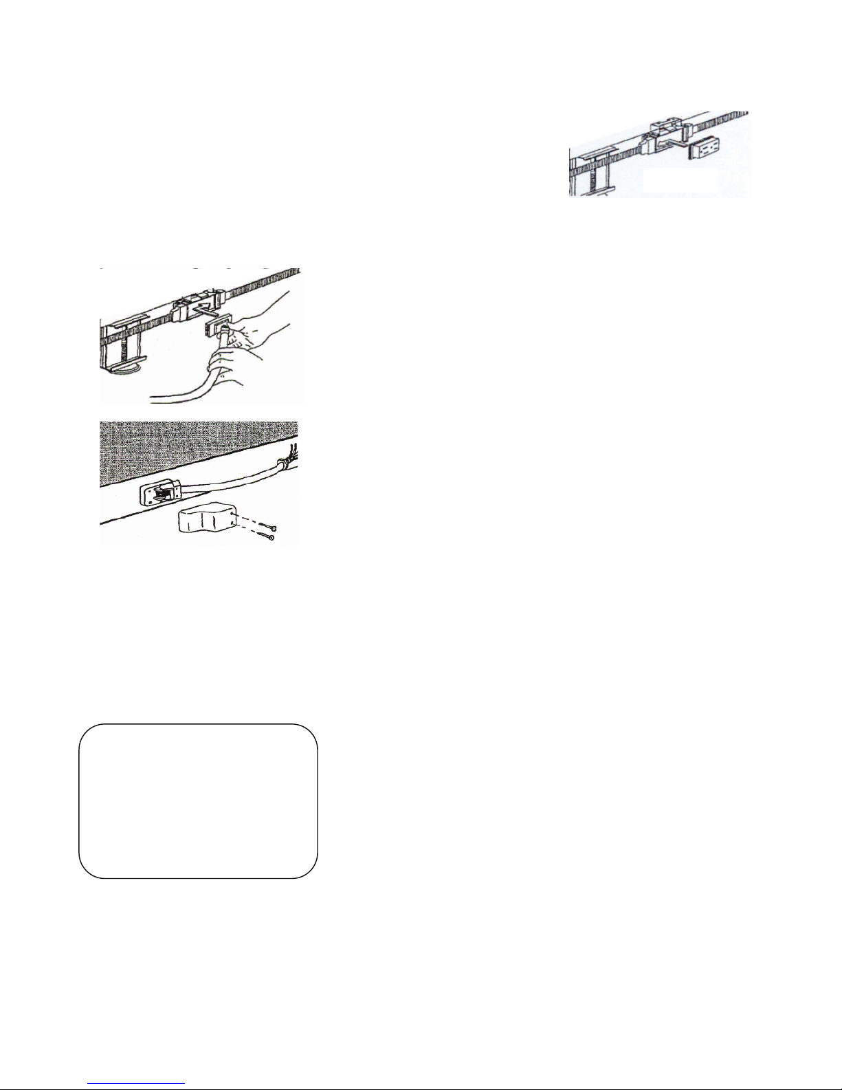
To install Duplex Receptacles
Slide and snap duplex receptacles into each Power Distribution
block where indicated according to electrical plan. Knock out
appropriate duplex covers on each base cover.
To remove duplex receptacle, press release tab on power block and
slide duplex receptacle out.
Power Entry
1. Insert end into power distribution harness block and slide
into position until you hear an audible ‘click’; thread free
end through panel base side cover and install base side
cover.
2. Rotate conduit to the right or left and add Power Entry
cover, Secure with two screws provided. Power Entry is
now ready for electrician to hardwire the connection to the
building supply.
• End Feed and Ceiling Feed cables connect to
power distribution block male terminals on end of
block.
WARNING
• Risk of Fir e or Electrical Shock. Each panel must be connected to only one source of electrical
supply. Be sure to turn off panel board switch while installing or removing power entry.
• Power Entry must be installed by a licensed electrician.
Wiring Guide
Gray
White
Green/Yellow
Green
Pink
Blue
Red
Black
AO1 / AO2
/ AO2 PolyPanells
Neutral 2
Neutral 1
Isolated Ground
Ground
Hot Circuit 4
Hot Circuit 3
Hot Circuit 2
Hot Circuit 1
15
Page 16

Base & Connector Raceway Management
O
pening Panel Base Side Covers:
Side covers are retained by the top channel and pivot at the baseplate.
1. To remove side cover, start at one end and press down on the top
edge of the side cover to clear the lip from the top channel; pull
toward you as your finger continues pressing down on the top edge
as it slides along toward the other end.
2. Rotate side cover down toward you to allow access to the cabl
m
anagement channel.
Closing Panel Base Side covers:
Note: Connector trim covers must be closed before closing side covers.
e
1. Start at one end of the side cover
and press down on the top edge
until the lip is under the t
hannel.
c
2. While holding that end in position,
press and run finger along the to
dge seating the rest of the li
e
un
der the top channel
C
onnector Trim Covers:
•
Trim covers are completely
.
installed on all post connectors, except 4-way connectors which have a base post but no trim cover.
•
Trim covers pivot at the base and hold their position with a latch that engages the connector.
•
To release the trim cover, press down and in with a flat blade screw driver, near the center at top. When the
tr
im co ver latch clears the edge of the connector, rotate th e tr im cover back.
Connector
Trim
Cover
Support
Post
op
Panel
Side Cover
Lip
p
Top Channel
Side Cover
Rotate
p
Baseplate / Hinge
Adjustab le Glide
Trim
Cover
Connector
Support
Post
Trim
Covers
Hinge
Support
Post
Connector
2-Way 90˚ Connector
AO1 / AO2 / AO2 PolyPanells
180˚ Connecto
2-Way
r
Trim
Cover
2-Way 90˚ Connector--
Closed
3-Way
Connector
Support
Post
Latches
Connecto
r
16
Page 17
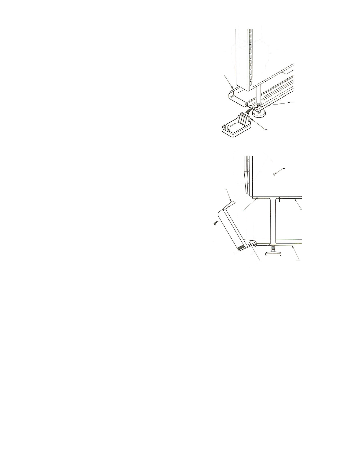
Wire Management End Cap Installation and Removal:
Note: End caps must be installed before closing panel
base side covers.
To Install:
1. Insert end cap hooks into the baseplate slo
shown at right.
as
ts,
2. Rotate the end cap upward until the end cap
l
atch catches the top channel hook. Confirm, by
pulling back on the top of the end cap.
Side Cover
(open)
Baseplate
Slots
To Remove:
1. Use a flat-blade screw driver to pry down
he end cap latch beneath the panel end trim
t
When the latch clears the top channel hook, pu
2.
back on the top of the end cap until the end cap
h
ooks disengage from the baseplate.
on
End Cap Hooks
.
ll
Panel
End Cap
Latch
Top Channel
Baseplate
Rotate
Top
Channel
Hook
End Cap Hook
AO1 / AO2 / AO2 PolyPanells
17
Page 18
Work Surface Installation
Principals apply to both AO1 and AO2. Original AO1-style, with retainer strips to locate work surface within cantilever
support arms, show; AO2 utilizes separate ‘button’ and ‘pin’ screws instead.
•
Work surfaces include pilot holes for standard location at each end.
•
Work surface spans should not exceed 48” without proper depth support such as cantilever support arm, clear-access
support panel, C-leg or dual-tube peninsula support leg. Sagging and warping of work surface will occur without a reinforcing
channel attached beneath.
•
Load capacities:
o
Up to, and including, 48”w (24”d, 30”d): 200lbs.
o
Less than, and including, 96”w (25”d, 30”d): 250lbs.
•
Warning: Load capacities, as listed, include the total load of the work surface, including storage components hanging from
the work surface such as pencil drawers and box/file hanging pedestals. Failure to observe the recommend loads and
applications will result in unsafe usage conditions which could result in product failure and/or personal injury.
•
Work surfaces can be adjusted in 1”-inc h increments on either panels or wall tracks . Ty pic al w ork surface heights are:
o
Machine usage/full-time keying: 25” from floor to top surface
o
Sit-down/Typical desk usage: 28” –30”, depending on size of person; 29” most normal
o
Stand-up height: 36”--42”
Set top of cantilever at 1” below desired work surface height
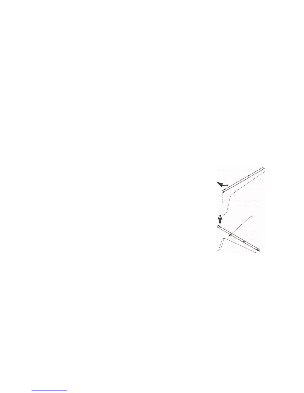
To install cantilever support arms:
1. Engage either left-hand or right-hand support arm in the appropriate panel side or wall hanger strip at the desired
height. See illustration. The cantilever support arm must rest fully beneath the work surface and flush to the end.
Important note:
AO1/AO2-style support arms and hanging brackets which attach to panels
and wall hanger strips have a built-in anti-dislodgement feature—the bracket ‘teeth’ are
curved requiring the bracket to be engaged in the following manner:
a. Tip the top, back of the bracket into the slotted track of a panel or wall
hanger strip so that the top tooth will engage first.
b. Position the bracket slightly offset to the outside of the components
location and, with the top tooth engaged, drop the rest of the bracket
against the slotted channel and into position.
c.
Tap the bracket firmly downward to securely seat the bracket
.
Cantilever
Support
Arm
AO1 / AO2 / AO2 PolyPanells
18
Page 19
Corner Work Surface Installation
Principals apply to both AO1 and AO2. Original AO1-style with retainer strips to locate work surface within cantilever
support arms shown. AO2 utilizes separate ‘button’ and ‘pin’ screws instead of “skate” retainers; “Button” is mounted rearmost on the work surface and fits into the keyhole slot of the cantilever while “pin” is mounted ahead of the “button” and fits
into the hole just behind the leveling screw at the front top end of the cantilever support arm.
•
Work surfaces include pilot holes for standard location at each end.
•
Load capacity: 200lbs.total load of the work surface, including weight of any component attached to the underside such as a
keyboard tray.
•
Failure to observe the recommend loads and applications will result in unsafe usage conditions which could result in product
failure and/or personal injury.
•
Work surfaces can be adjusted in 1”-inch increments on either panels or wall tracks. Typical work surface heights are:
o
Machine usage/full-time keying: 25” from floor to top surface
o
Sit-down/Typical desk usage: 28” –30”, depending on size of person; 29” most normal
o
Stand-up height: 36”--42”
Set top of cantilever at 1” below desired work surface height
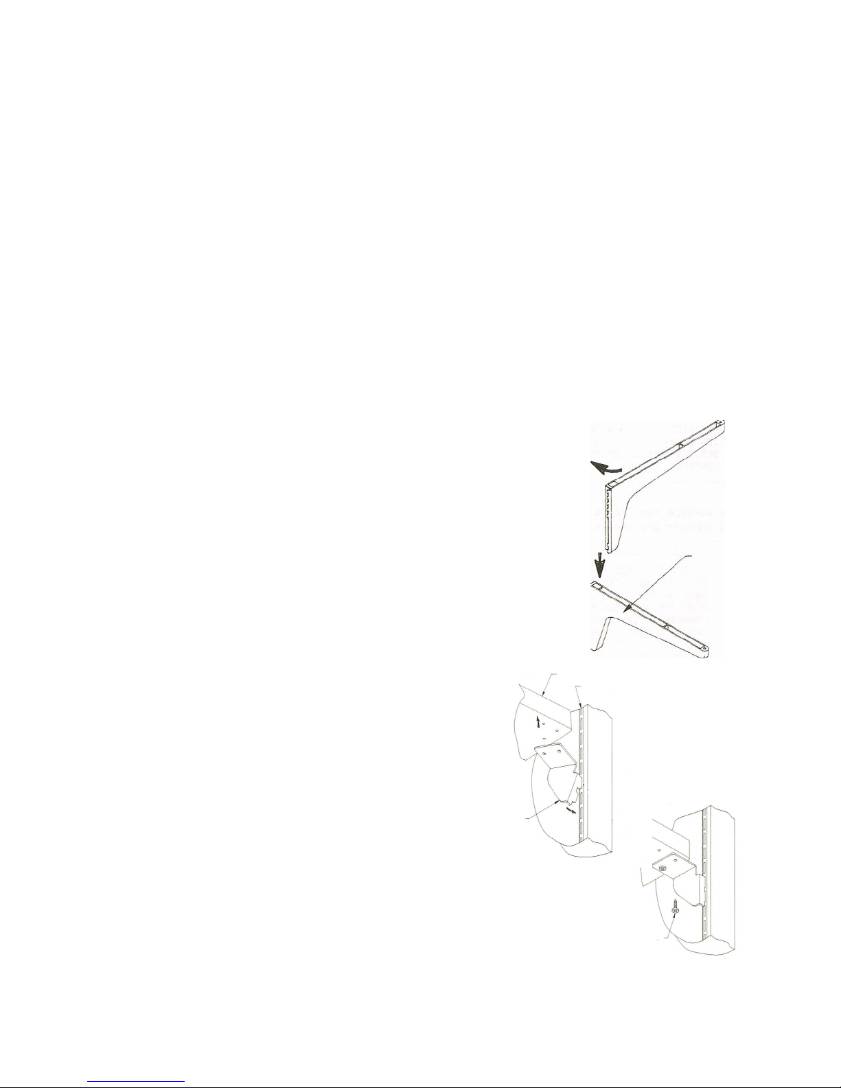
To install cantilever support arms and work surface support bracket:
1. Engage either left-hand or right-hand support arm in the appropriate panel side or wall hanger strip at the desired
height. See illustration. The cantilever support arm must rest fully beneath the work surface and flush to the end.
Important note:
AO1/AO2-style support arms and hanging brackets which attach to panels
and wall hanger strips have a built-in anti-dislodgement feature—the bracket ‘teeth’
are curved requiring the bracket to be engaged in the following manner:
a. Tip the top, back of the bracket into the slotted track of a panel or wall
hanger strip so that the top tooth will engage first.
b. Position the bracket slightly offset to the outside of the components
location and, with the top tooth engaged, drop the rest of the bracket
against the slotted channel and into position.
c.
Tap the bracket firmly downward to securely seat the bracket
.
2. In the same manner, engage the opposite side support arm.
3. Insert Work Surface Support Bracket (part number HMP455.02) in either panel
slot at the rear corner connector or wall hanger strip, depending on whether the
bracket is a ‘left’- or ‘right’-hand bracket as shown below, right.
Screw
Work Surface
Hanger Frame
Cantilever
Support
Arm
AO1 / AO2 / AO2 PolyPanells
19
Page 20
Corner Work Surface Installation--continued
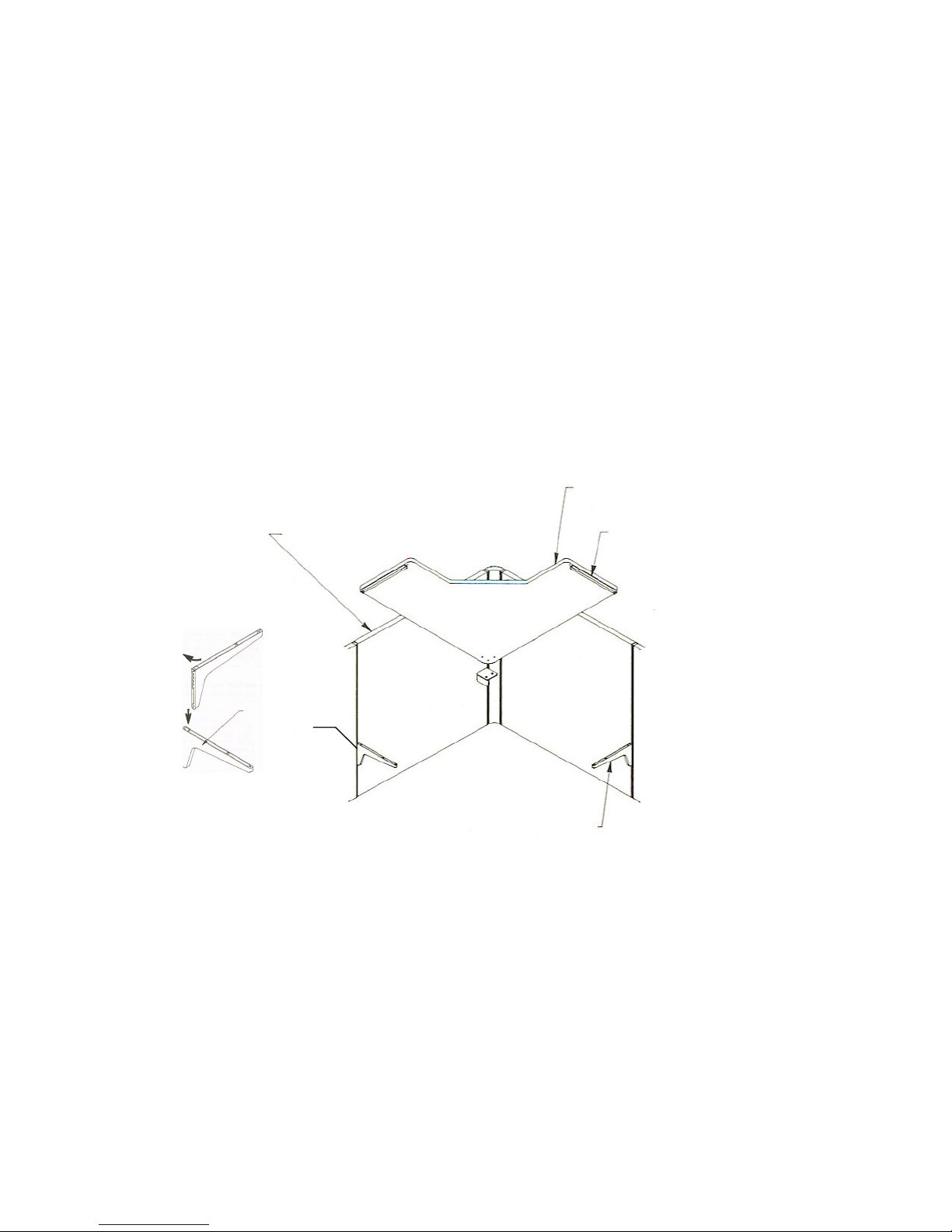
6. Position the corner work surface over support hardware as shown below. Engage the retainer or
“button” and “pin” screws of one side into the cantilever support arm as shown below, right. On
the other side, eliminate the “button” screw, using the “pin” screw to locate it on the support arm.
7. Lower corner work surface fully into position and be sure it is securely seated on all three
support brackets.
Note: early AO1/AO2-style retainers are used with cast-aluminum cantilever support arms; button/pin screws are
used with pressed steel cantilevers.
8. Attach the work surface to the rear corner bracket with two screws; tighten screws securely.
9. Use work surface connecting plates to join corner work surface to adjoining work surfaces.
10. Adjust hex screw at front of cantilever to level work surface, front-to-back.
Corner Work
Surface
Panel
Cantilever
Support Arm
Cantilever
Support Arm
Retainer (original AO1 “skate”-style
shown). Replaced by “button” and
“pin” screws for use with steel
cantilever support arms.
AO1 / AO2 / AO2 PolyPanells
20
Page 21
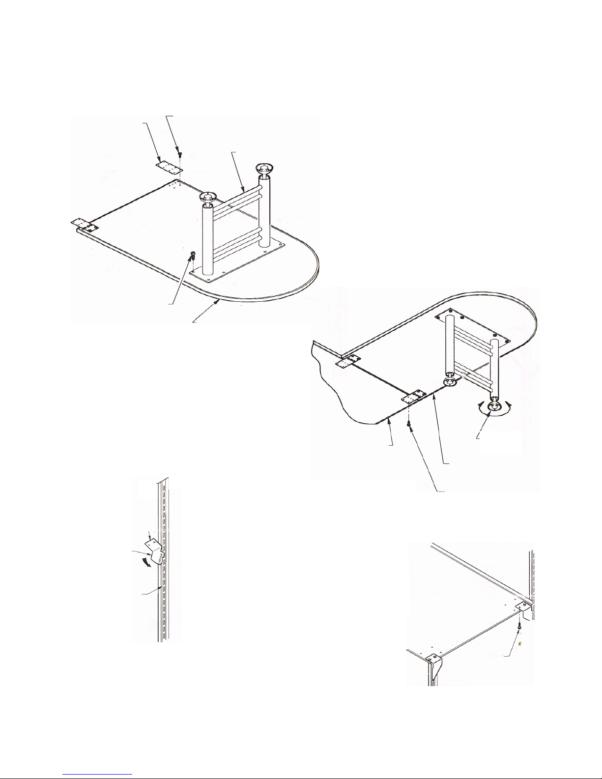
Peninsula Work Surface Installation
g supp
g
Work Surface-supported Installation:
Work surface connedtor
plate—Mount first to
adjoining mounted work
surface so that they support
the peninsula work surface
when inverted after
installin
ort le
Screw
Screw
Peninsula Work
Surface, top down
Peninsula support
leg, single or dual-leg
1. Lay work surface, underside up, on a
clean, padded surface.
2. Center support leg, whether single or
dual-leg, set back from end the
depth (radius) of the surface. Secure
with screws.
3. Mount two work surface connecting
plates to the adjoining, mounted work
surface as shown below.
4. Place peninsula work surface over the
connecting plates and secure with
screws.
5. Adjust glides to level peninsula work
surface.
Peninsula Work Surface Installation
Panel-supported Installation:
1. Engage top tooth of work surface
support bracket (brackets are handed)
Right Hand
bracket
shown
Work Surface
Support Bracket,
HMP455.02
“Tip” bracket into slott ed
channel of panel or wa ll
hanger strip in the same
manner as cantilever
support arm
into slotted channel of panel frame or wall hanger strip, as shown
at right. Then rotate bottom of bracket
down into position of slotted channel.
Typical height for installation is
approximately 28” from floor to the top
of the support bracket.
2. With the panel clips firmly seated,
lower the peninsula work surface onto
the brackets as shown, below right.
3. Drive two screws into each bracket
until tight.
End of adjoining,
mounted work surface
Peninsula
Work Surface
Screw
Use two screws
in each bracket
Glide
AO1 / AO2 / AO2 PolyPanells
21
Page 22
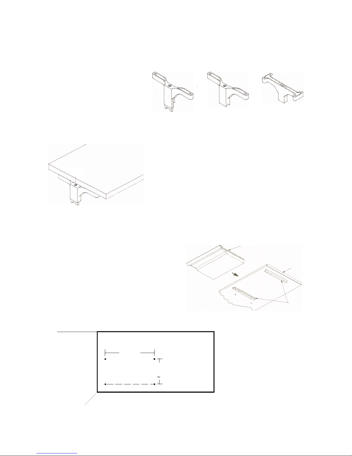
Transaction Surface Installation
1. Turn out allen screw of finished end top block or panel-to-panel connector draw block, depending
on application.
2.Remove top block or draw
block and replace with
appropriate transaction counter
bracket. See description of
each application at right, below
with respective transaction
counter support bracket.
In
stall connector or finished
3.
end as described in “Panel
Installation” above.
End Support:
Use to replace finished
end top block at the
end of a panel run
which will support a
transaction counter.
Mid End Support:
Use to replace panelto-panel connector top
draw block where a
transaction counter
ends at a panel
junction.
Center Support:
Use to replace panelto-panel connector top
draw block where a
transaction counter
spans across a panel
junction.
4. Position transaction counter over supports and align in
both directions. Attach counter to supports with #12-10
x 1 Flat Head Philips screws.
Shown:
End Support
Pencil Drawer Installation
1.
Attach drawer bearers to work surface as
shown at right with flat-head wood
screws supplied
.
Note: Closed-end of drawer bearers face
rear of work surface.
2. Use drawer bearer dimensions/spacing
shown below wherever pencil drawer is
desired.
20 ”
front edge
10”
3 1/8”
AO1 / AO2 / AO2 PolyPanells
22
Page 23
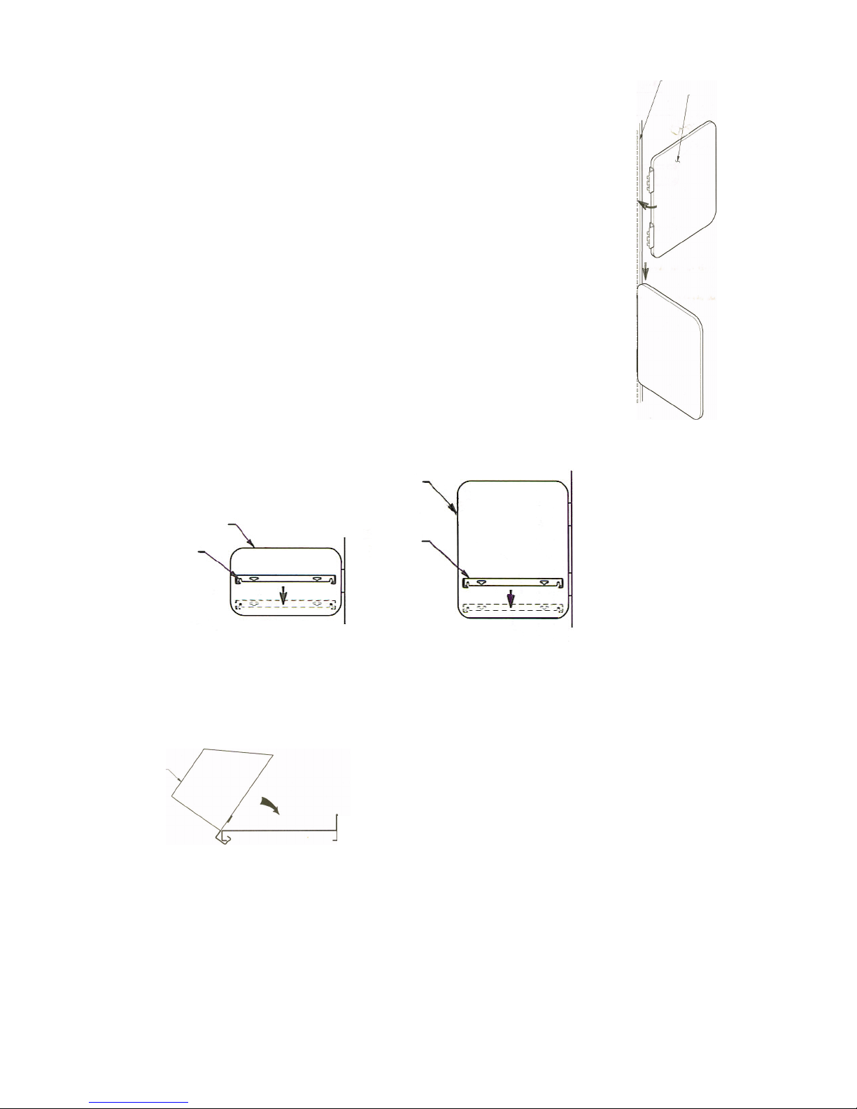
Wall Track
Shelf Installation
Note:
All screws must be firmly tightened. Failure to do so may cause the
shelf to fall, causing product damage or personal injury.
1. Loosen both bottom shelf mounting screws on each end panel to
reveal approximately 1/8” of screw thread. Bottom screws are for
the shelf; top screws are for the flipper door assembly or additional
shelf, if specified.
2. Engage shelf end panel at desired height in slotted hanger frame
of panel or wall track channel as show at right, top.
3. Swing shelf end panel to perpendicular with panel or wall and lock
shelf end panel in place by pushing down on end panel to seat the
bracket. Tap firmly with plastic mallet to ensure end panel is fully
seated on hanger frame or wall hanger strip.
4. Position end panels perpendicular to wall and slide shelf straight in
between shelf end panels, just above the mounting screws. Seat
shelf pan securely on the mounting screws and tighten with a
Philips screw driver; be certain to tighten all screws firmly.
End Panel
Shelf
End Panel
Shelf Pan
Shelf Divider
Shelf
Divider
Shelf Pan
7”h Shelf 15”h Shelf
1. Install shelf divider by tilting divider forward and
hook under lip of shelf as shown.
2. Pivot divider so that it rests flat on the shelf.
Side view
AO1 / AO2 / AO2 PolyPanells
23
Page 24
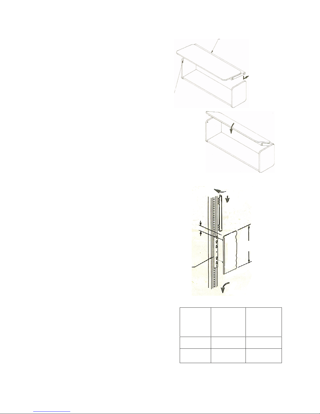
Flipper Door Installation
y
1. If a flipper door cover is to be installed, first
install the shelf unit but do not tighten the
screws to the shelf end panel.
2. Loosen top mounting screws on both end
panels to reveal approximately 1/8” of
screw thread.
3. With the flipper door assembly in the
‘open’ position (shown), position the rear
slots of the flipper door assembly over
the rear screws of the shelf end panel.
4. Slide the flipper door assembly back until the
front slots drop over the front screws.
5. Seat flipper door assembly firmly over the four
top shelf end panel screws then securely
tighten all four flipper cover screws then all
four shelf pan screws.
Tack Board & Marker Board Installation
1. Position and engage the hanger clips in panel
joint or on wall hanger strip (hanger clips are
universal) at desired height. See table below
right for typical locations.
2. Position board with the mounting screws just
above the hanger clips in the slots of the
hanger clips as shown at right.
3. Press board against hanger clips and down to
engage the mounting screws securely into the
hanger clip notches.
Threaded hole
and
screw
Flipper D oor
Assembl
B
A
Marker Board Maintenance Notes:
•
Use only dry erasable markers; never use permanent
markers!
•
If permanent marker is accidentally used, remove marks by
writing over the marked area with dry erasable marker and
immediately wiping it clean.
•
Board can be wiped clean with a standard felt eraser. Use
specifically-designed white board cleaner to aid cleaning and
to minimize marker residue.
•
If necessary, clean marke r boa rd with lacquer thinner to eliminate any
residue left on the board from permanent markers or other non-approved
writing instruments.
•
Note: Lacquer thinner is extremely flammable and harmful,
or fatal, if swallowed. Vapor is harmful and is an eye and
skin irritant. Avoid contact with skin or eyes; do not use near
a heat source—fire or personal injury may result.
•
Never use an abrasive cleanser on this surface which will cause the
surface to deteriorate rapidly and deliver poor performance.
AO1 / AO2 / AO2 PolyPanells
Hanger Clip
Dimension
A
Tack Board
Height
Dimension
B
Mounting
Screw
Dimensions
(from top)
11 ” 1”, 8” 40”
15 ” 4”, 11” 41”
Dimension
from floor to top
of hanger clip
(approximate)
24
Page 25
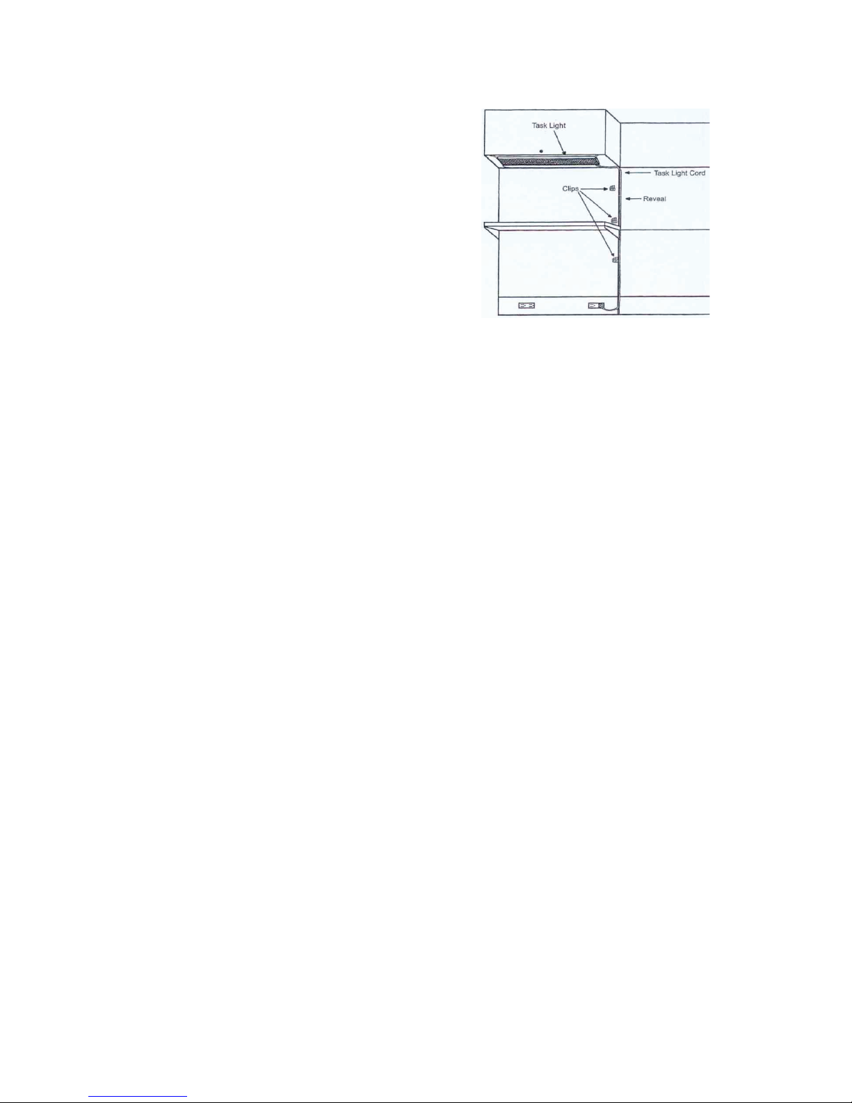
Task Lights
1.
Install Task Light according to manufacturer's
instructions, included with the light.
2.
If using optional cord management clips, align task
light cord inside reveal between panels. Plug light
cord into outlet in panel base.
3. Use at least 3 cord clips per light to hold in place.
Storage Pedestals
1. Position storage component under work surface at desired location.
2. Remove pedestal drawers by fully extending drawer and slightly prying the drawer slide
mechanism away from the drawer box using a slotted screw driver or mini
Wonderbar/prybar from the bottom of the slide mechanism just behind the drawer front.
Simultaneously lift the drawer box slightly away and repeat on the other side of the drawer.
3. Now hold both sides of the drawer box and pull toward you to disengage the tabs supporting
the rear of the drawer box; pull drawer away entirely. Remove each drawer.
4. Level storage cabinet by adjusting each of the four glides until the top surface of the
storage cabinet is flush with the work surface.
5. Use screws supplied with storage component to secure its four corners to the work
surface through holes in the top frame.
6. Replace the drawers in the reverse sequence: align and insert tab/bayonet on side/rear of
drawer box to slot on drawer slide; then attach in the same manner at front.
7. Test drawers for smooth operation; adjust if necessary.
AO1 / AO2 / AO2 PolyPanells
25
 Loading...