

Page 1

IntraPort Enterprise-8
VPN Access Server
Installation Guide
Compatible Systems Corporation
4730 Walnut Street
Suite 102
Boulder, Colorado 80301
303-444-9532
800-356-0283
http://www.compatible.com
Page 2

IntraPort Enterprise-8 VPN Access Server Installation Guide, Version 1
Copyright © 1999, Compatible Systems Corporation
All rights reserved. IntraPort Enterprise, RISC Router, MicroRouter and CompatiView are
trademarks of Compatible Systems Corporation. Other trademarks are the property of their
respective holders.
Part number: A00-1869
FCC Notice: This product has been certified to comply with the limits for a Class A computing
device, pursuant to Subpart J of Part 15 of FCC Rules. It is designed to provide reasonable protection against radio or television communication interference in a commercial environment.
Operation of this equipment in a residential area could cause interference with radio or television
communication.
Page 3

Table of Contents
Introduction to the IntraPort Enterprise-8 1
A NOTE ABOUT REMOTE CLIENT CONNECTIONS 1
NTRAPORT ENTERPRISE-8 INSTALLATION OVERVIEW 1
I
I
NTRAPORT ENTERPRISE-8 MANUAL OVERVIEW 2
Chapter 1 - Getting Started 3
A FEW NOTES 3
Please Read the Manuals 3
Warranty and Service 3
Getting Help with the IntraPort Enterprise-8 3
HAT YOU WILL NEED TO GET STARTED 4
W
Supplied with the IntraPort Enterprise-8 4
Additional Items Needed for Installation 4
Chapter 2 - Mounting Instructions 5
PLACEMENT CONSIDERATIONS 5
SAFETY GUIDELINES 5
PARTS AND TOOLS 6
CHANGING THE POWER SUPPLY VOLTAGE SETTINGS 6
Installing Mounting Ears and Handles 7
Rack-Mount Brackets 8
Right Bracket Installation 9
Left Bracket Installation 10
Securing the Shelf 11
Moving the Unit into the Rack 12
Placing the Unit in an Equipment Rack 13
Securing the Unit to the Rack 14
Chapter 3 - Network Installation 15
PHYSICAL CONNECTION REQUIREMENTS 15
CONNECTING THE SERVER TO THE ETHERNET 16
CONNECTING A MANAGEMENT CONSOLE 17
POWERING UP THE SERVER 17
Power Alarm Information 17
Chapter 4 - CompatiView Software Installation 18
COMPATIVIEW FOR WINDOWS 18
System Requirements 18
Installation and Operat io n 18
Transport Protocols and CompatiVie w 19
Chapter 5 - Command Line Management 20
OUT-OF-BAND COMMAND LINE MANAGEMENT 20
TEMPORARILY RECONFIGURING A HOST FOR COMMAND LINE MANAGEMENT 20
SETTING UP TELNET OPERATION 21
i
Page 4

Table of Contents
Chapter 6 - Basic Configuration Guide 22
ETHERNET INTERFACE CONFIGURATION 22
IP Protocol 22
IP Settings for Setups in Parallel with a Firewall 22
IP Settings for Setups Behind a Firewall 23
IPX Protocol 24
Required for IPX 24
Suggested for IPX 24
AppleTalk Protocol 24
Required for AppleTalk 24
Suggested for AppleTalk 24
Configuring the Server for LAN-to-LAN Tunnels 24
Required for LAN-to-LAN Tunnel Configurations 24
Suggested for LAN-to-LAN Tunnel Configurations 24
Configuring the Server for IP and IPX Client Tunnels 25
Required for Client Tunnel Configurations 25
Suggested for Client Tunnel Configurations 25
VPN User Database 25
Setting up RADIUS Authentication 26
Setting the IntraPort Enterprise-8 for a RADIUS Server 26
RADIUS Server User Authentication Settings 26
Setting up SecurID Authentication 27
Setting the IntraPort Enterprise-8 for an ACE/Server 27
ACE/Server Settings 27
SAVING A CONFIGURATION FILE TO FLASH ROM 28
Chapter 7 - Shipping Defaults 29
DEFAULT PASSWORD 29
ETHERNET INTERFACES 29
IP Defaults 29
IPX Defaults 29
AppleTalk Defaults 29
Chapter 8 - LED Patterns and Test Switch Settings 30
INTRAPORT ENTERPRISE-8 LED PATTERNS 30
Over Temp 30
Sys Ready 30
General Indicators 30
Ethernet Traffic Indicat ors 30
Load % Indicators 30
INTRAPORT ENTERPRISE-8 SWITCH SETTINGS 31
Appendix A - Connector and Cable Pin Outs 32
PIN OUTS FOR DB-25 MALE TO DB-25 FEMALE CONSOLE CABLE 32
ii
Page 5

Table of Contents
Appendix B - Downloading Software From Compatible Systems 33
Appendix C - Security Dynamics ACE/Server Information 34
Appendix D - Adding or Replacing RIOP Cards 35
Appendix E - When the “Over Temp” Light Comes On 36
REPLACING OR CLEANING THE INTRAPORT ENTERPRISE-8 AIR FILTER 36
Appendix F - Terms and Conditions 37
iii
Page 6

Table of Contents
Figure 1. Location of Voltage Switch on the Power Supply 6
Figure 2. Installing Mounting Ears and Handles for a Standard Equipment Rack 7
Figure 2.1. Installing Mounting Ears for a Telco Rack 7
Figure 3. Rack-Mount Brackets 8
Figure 4. Fastening the Right Bracket to the Rack 9
Figure 5. Fastening the Left Bracket to the Rack 10
Figure 6. Lowering the Shelf 11
Figure 6.1. Securing the Shelf 11
Figure 7. Moving the Unit into a Standard Equipment Rack 12
Figure 7.1. Moving the Unit into a Telco Rack 12
Figure 8. Placing the Unit in a Standard Equipment Rack 13
Figure 8.1. Placing the Unit in a Telco Rack 13
Figure 9. Securing the Unit to the Rack 14
Figure 10. IntraPort Enterprise-8 VPN Access Server 15
Figure 11. Detail of RIOP Cards 16
Figure 12. Detail of Power Units 17
Figure 13. Removing and Replacing an RIOP Card or Cover Plate 35
Figure 14. Removing the Filter Cover Plate 36
iv
Page 7

Introduction to the IntraPort Enterprise-8 1
Introduction to the IntraPort Enterprise-8
Congratulations on your purchase of the IntraPort Enterprise-8 VPN Access Server. The
IntraPort Enterprise-8 s uppor ts u p to 512 LAN -to-L AN tunn els and up t o 40, 000 simu ltan eous
remote client connections.
In addition, it offers DES and 3DES encryption using built-in hardware coprocessors.
A Note About Remote Client Connections
In order to create a tunnel to a network over the Internet, remote users must run VPN Client
software on a Windows95/98 PC, Windows NT PC, Mac OS, Linux, or Sun Solaris computer
which is connected to the Internet via PPP or Ethernet.
The IntraPort VPN Clients are applications which set up the remote access VPN tunnels to the
IntraPort Enterprise-8 VPN Access Server and make sure that appropriate data gets sent.
The clients work in conjunction with your communications software. Connections can be
made to the Internet via PPP software or over a local intranet via a workstation’ s LAN adapter.
Together, these components provide cost-effective on-demand connections to your corporate
network.
IntraPort Enterprise-8 Installation Overview
This manual will help you mount the IntraPort Enterprise-8 VPN Access Server in a rack and
install it on your Local Area Network. It also includes general maintenance information and
some technical specifications. For the most up-to-date information available on the IntraPort
Enterprise-8 VPN Access Server, please visit the Technical Support section of our Web site at:
http://www.compatible.com.
In short, the installation steps are:
1. Mount the IntraPort Enterprise-8 in a rack or other appropriate setting.
2. Install the IntraPort Enterprise-8 hardware on your Ethernet LAN and connect the
10/100 twisted-pair Ethernet interfaces to Fast Ethernet or Ethernet hubs.
3. Select the management tool you wish to use with the server. If you want to use the
CompatiView management software, you must install the software on a Windows PC
computer which is connected to your network.
4. Configure the IntraPort Enterprise-8 LAN and tunnel parameters using the manage-
ment tool you have chosen.
5. Install and Configure the VPN Client software for remote users. (See the VPN Cli-
ent Reference Guide.)
Page 8

Introduction to the IntraPort Enterprise-8 2
IntraPort Enterp ri se-8 Man u a l Overvi ew
The manual is divided int o s everal s ecti ons th at sh oul d pr ovi de you w it h the basic information
you will need to use the IntraPort Enterprise-8 on your network. For the latest documentation
on Compatible Systems products, including the most current version of this manual, visit the
Technical Support section of our Web site.
Chapter 1 - Getting Started
This part of the manual describes the contents of the IntraPort Enterprise-8 package and
emphasizes the preparation and equipment you will need to install the server.
Chapter 2 - Mounting Instructions
This part of the manual includes detailed instructions for mounting the IntraPort Enterprise-8
in a variety of equipment racks and instructions on changing the voltage switch settings.
Chapter 3 - Network Installation
This part of the manual includes step-by-step instructions on how to conn ect the server to your
local Ethernet and power it up. Instructions are included for twisted-pair Ethernet environments.
Chapter 4 - CompatiView Software Installation
This part of the manual describes how to install CompatiView, Compatible Systems’ GUI
(Graphical User Interface) management software which is included with your server.
Chapter 5 - Command Line Preparation
This part of the manual provides basic instructions for using command line management and
text-based configuration to configure a server.
Chapter 6 - Basic Configuration Guide
This part of the manual provides a minimal list of parameters that must be entered into a server
for proper operation.
Chapter 7 - Shipping Defaults
This part of the manual lists factory defaults.
Chapter 8 - LED Patterns and Switch Settings
This part of the manual describes the LED indicators and the test switch settings.
Appendices
This part of the manual includes add itional informat ion that mi ght be of in terest t o you such as
technical specifications, some maintenance procedures and instructions for downloading
current so ftware.
Page 9

Chapter 1 - Getting Started 3
Chapter 1 - Getting Started
A Few Notes
Please Read the Manuals
The manuals included with your IntraPort Enterprise-8 VPN Access Server contain very
important information about installing and operating the IntraPort Enterprise-8. Please read
this manual, and refer to the management reference guides as required. It’s worth the few
minutes it will take.
Also, please fill out the warranty registration card and return it to us today. This will help us
keep you informed about updates to the IntraPort Enterprise-8 and future products available
from Compatible Systems.
Y o u can also register on the Web at http://www.compatible.com. If you’d like to be notified via
e-mail about new products and receive important news from Compatible Systems, please join
our e-mail list on the Web.
Warranty and Service
The IntraPort Enterprise-8 is covered by the Compatible Systems Integr ated Suppo rt Pack age,
which includes a lifetime comprehensive warranty, a twenty-four hour advance replacement
program, unlimited phone support and software upgrades for the life of the product. A 24 x 7
support plan is also available.
Compatible Systems maintains copies of current software updates on the Internet. You may
download product software from the Internet at any time. For more information on downloading current product software, see Appendix B.
Getting Help with the IntraPort Enterprise-8
If you have a question about the IntraPort Enterprise-8 and can’t find the answer in one of the
manuals included with the product, please visit the technical support section of our Web site
(http://www.compatible.com). This site includes extensive technical resources which may
answer many of your questions. You can also request technical support by filling out a brief
form. Technical support requests received via the Web form will receive expedited treatment.
You may also call Compatible Systems Corporation or send support questions via e-mail to
support@compatible.com. Compatible Systems' phone number is listed on the front of this
guide. We will be happy to help you.
Page 10

Chapter 1 - Getting Started 4
What You Will Need to Get Started
Before connecting the IntraPort Enterprise-8 VPN Access Server, please check the list below
to make sure that you have received all of the items that are supplied with the shipping
package(s).
You should also make sure you have any additional items that are necessary to connect the
server to your network.
Supplied with the IntraPort Enterprise-8
Please check your shipping package(s) for the following items:
• IntraPort Enterprise-8 unit
• 2 power cords
• One left rack-mount bracket
• One right rack-mount bracket
• Two mounting ears
• Two handles
• Two hand le spacers
• 14 mounting screws (10-32 undercut flat head)
• One DB-25 male to DB-25 female console cable
• One reusable replacement air filter
• CD-ROM including:
4 CompatiView software for Windows
4 Operating software
4 VPN Client software (Windows and Mac OS versions)
4 HTML version of product documentation (which can be vi ewed with your favorit e
Web browser)
• VPN Client Reference Guide
• CompatiView Management Software Reference Guide
• Text-Based Configuration and Command Line Management Reference Guide
• Warranty registration card
Additional Items Needed for Installation
• If you choose to rack-mount the IntraPort Enterprise-8, you will need to provide your
own screws or clips to secure the mounting brackets to the equipment rack. A more
detailed list of the items needed for mounting the server is in Chapter 2 - Mounting
Instructions.
• Before connecting the IntraPort Enterprise-8 to your network, you need to make sure
that you have the necessary interface cabling equipment. See Chapter 3 - Network
Installation for details.
Page 11

Chapter 2 - Mounting Instructions 5
Chapter 2 - Mounting Instructions
The IntraPort Enterprise-8 VPN Access Server is designed to be mounted in a 19-inch equipment rack or in a Telco rack. Compatible Systems pr ovid es all the p arts necessar y for s ecurin g
the supplied mounting brackets and ears to the device; however, due to the variety of equipment racks and mounting techniques, you will need to provide your own screws or clips to
secure the mounting brackets and ears to the equipment rack.
Placement Considerations
There are several things to consider when preparing to install the IntraPort Enterprise-8 VPN
Access Server.
• Do not place the server on the floor, since it will more quickly accumulate dust. As
alternatives to rack-mounting, it can be placed on a sturdy table or solid platform.
• A clean, air-conditioned environment is ideal.
• An open equipment rack (i.e., one without side enclosures or doors) is recommended
for adequate ventilation.
• The chassis requires 13.5 shelf positions (23.5 vertical inches) of rack space.
• While no rear clearance is required, the front of the server needs adequate clearance
for air circulation, RIOP card addition or replacement, cable connections, etc. At least
two feet of front clearance and one inch of top clearance are recommended.
• Load the equipment rack from the bottom. For stability, it is strongly recommended
that the IntraPort Enterprise-8 VPN Access Server be placed in the bottom half of an
equipment rack.
Safety Guidelines
v Note: When stacking other equipment on the IntraPort Enterprise-8 VPN Access Server, do
not exceed 35 pounds of evenly distributed weight on top of the server. Additional weight may
bend the case.
T o help en sure you r safety and minimize p otential damage to equipment, read an d follow these
guidelines before attempting to move or work on the IntraPort Enterprise-8 VPN Access
Server. These guidelines do not encompass all potential hazards. You must use good judgment
and due caution when working with this or any other electrical device.
• The default setting for the voltage switch on the power supplies for the Carrier-8 is for
a low input voltage (marked 115V on the switch). If your electrical system requires a
high input voltage on the power supp lies, you must change the settings before
ging in the server (for instructions, see Changing the Power Supply Voltage Settings).
• Never attempt to move the server using the RIOP card handles or the filter cover
opening. They will not su ppo rt t he wei ght of the device. Use the built-in si d e handles
and either the large mounting handles, if you have installed them, or the very bottom
of the chassis to move it (see Figures 2 and 2.1).
• The IntraPort Enterprise-8 VPN Access Server weighs approximately 110 pounds.
Moving the server requires at least two people, able to bear 55 pounds of weight
apiece. If your union or company policy outlines a lower maximum weight load per
person, use the appropriate number of people.
• Make sure you have a clear path between the server and the equipment rack, platform
or table before attempting to move it into place.
plug-
+ Warning: All power cords an d inter face cab les must be dis conn ected befo re you attempt to
move or work on the IntraPort Enterprise-8 VPN Access Server. Even the interface cables can
deliver lethal doses of electricity.
Page 12

Parts and Tools
Chapter 2 - Mounting Instructions 6
The following items are needed to install the mounting ears and handles on the IntraPort Enterprise-8 VPN Access Server.
• IntraPort Enterprise-8 unit
• Two mounting ears
• Two handles
• Two hand le spacers
• 14 mounting screws (10-32 undercut flat head)
• Phillip’s head screwdriver
In addition to the above items, the following items are needed to install the IntraPort Enterprise-8 VPN Access Server in an equipment rack.
• One left rack-mount bracket
• One right rack-mount bracket
• One DB-25 male to DB-25 female console cable
• Tape measure (optional)
• Level (optional)
• Your own screws or clips, for fastening the brackets to the rack
• At least two people to lift the device into place. Do not attempt to move the device
into the rack or onto a table or platform by yourself.
Changing the Power Supply Voltage Settings
The default setting for the voltage switches on the server’s power supplies is for a low input
voltage (marked 115V on the swi tch) . If y our elect rical s ystem r equires a hig h input volt age on
the power supplies, you must change it manually on the device before
To change the settings:
1. Make sure the server is powered down and not connected to any power source.
2. Using a small screw driver, change the voltage switches to the desired setting (230V
for high input voltage, 115V for low input voltage).
Figure 1. Location of Voltage Switch on the Power Supply
plugging the device in.
Page 13
Chapter 2 - Mounting Instructions 7
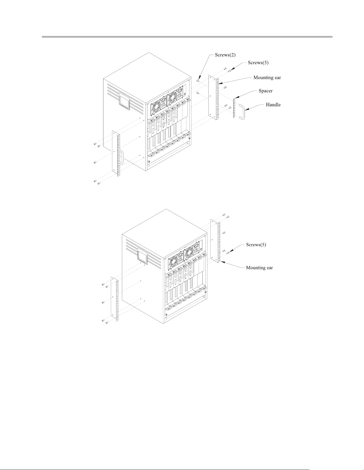
Installing Mounting Ears and Handles
Figure 2. Installing Mounting Ears and Handles for a Standard Equipment Rack
Figure 2.1. Installing Mounting Ears for a Telco Rack
The mounting ears should be installed on the IntraPort Enterprise-8 VPN Access Server
whether you are planning to rack-mount it or not. The handles need not be installed for Telco
rack mounts because there is not enough finger room to use them, but the handles are recommended for all other installations.
If you are not going to rack-mount the IntraPort Enterprise-8, it is recommended that you
install the mounting ears and handles using the Standard Equipment Rack position (as shown
in Figure 2).
1. Use the supplied screws and fasten the mounting ears to the sides of the device using
5 screws on each side as shown in Figure 2 (for a standard equipment rack) or in Figure 2.1 (for a Tel co rack).
2. Use the supplied screws and fasten the handles and spacers to the center o f the mounting ears as shown in Figure 2.
Page 14
Rack-Mount Brackets
Chapter 2 - Mounting Instructions 8
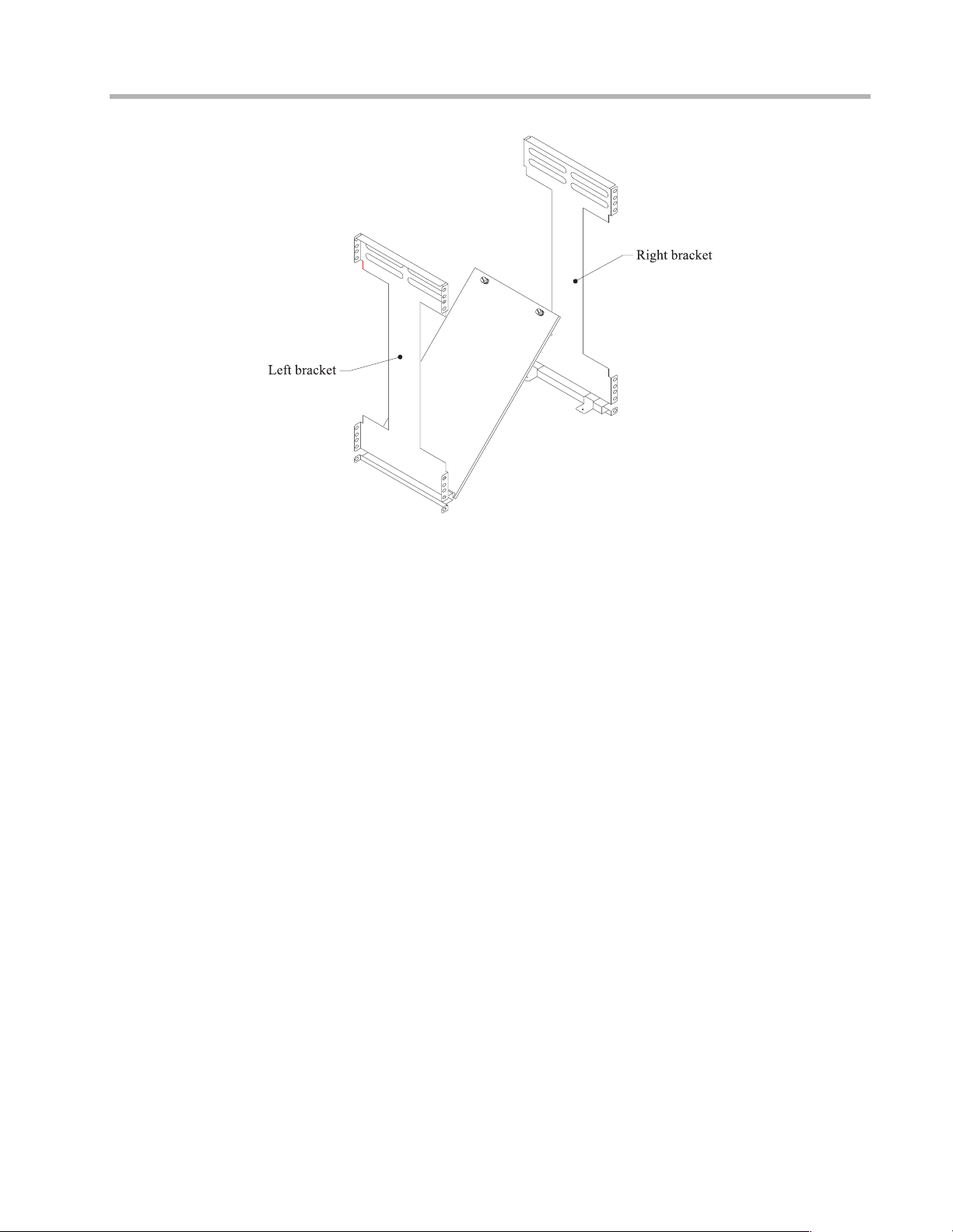
Figure 3. Rack-Mount Brackets
Brackets (shown in Figure 3) are provided for mounting the IntraPort Enterprise-8 in a standard 19-inch equipment rack or a Telco rack. Note that the left bracket features a fold-down
shelf which maintains the proper alignment of the brackets in the rack, but does not bear the
weight of the unit. The ledges at the bottom of the brackets bear the weight of the unit until it is
securely attached to the equipment rack. You will need to provide your own screws or clips to
fasten the brackets and mounting ears to the equipment rack.
Page 15

Right Bracket Installation
Figure 4. Fastening the Right Bracket to the Rack
Chapter 2 - Mounting Instructions 9
1. It is recommended that you mark on the equipment rack exactly where you want the
top of the two mounting brackets to go on the device in order to make sure that they
are level with each other (using a level if necessary). Once you have determined the
desired location, fasten the right brack et to the rack usi ng your own s crews or clip s, as
shown in Figure 4.
• At least 2 screws must be used to fasten the top of the bracket to the rack (using
any two holes on the rack tab).
• At least 3 screws must be used to fasten the bottom of the bracket to the rack.
One of the screws must be used to fasten the very bottom hole in the rack tab.
Page 16

Left Bracket Installation
Figure 5. Fastening the Left Bracket to the Rack
Chapter 2 - Mounting Instructions 10
1. It is recommended that you mark on the equipment rack exactly where you want the
top of the two mounting brackets to go on the device in order to make sure that they
are level with each other. Once you have determined the desired location, fasten the
left bracket to the rack using your own screws or clips, as shown in Figure 5.
• 2 screws must be used to fasten the top of the bracket to the rack (using any two
holes on the rack tab).
• At least 3 screws must be used to fasten the bottom of the bracket to the rack.
One of the screws must be used to fasten the very bottom hole in the rack tab.
Page 17

Securing the Shelf
Chapter 2 - Mounting Instructions 11
Figure 6. Lowering the Shelf
1. Lower the shelf onto the tabs protruding from the right bracket as shown in Figure 6
and use the thumb screws to fasten the shelf to the bracket. The brackets and shelf
should look like Figure 6.1 when fully installed.
Figure 6.1. Securing the Shelf
Page 18

Chapter 2 - Mounting Instructions 12
Moving the Unit into the Rack
Never attempt to move the server using the RIOP card handles or the filter cover opening.
They will not support the weight of the device. Use the built-in side handles and either the
large mounting handles, if you have installed them, or the very bottom of the chassis to move
it.
Figure 7. Moving the Unit into a Standard Equipment Rack
1. T wo people are needed to move the unit into the rack. Do not attempt to move the unit
by yourself. Holding the unit by the front and side handles as shown in Figure 7, carefully lift the unit and place it into the brackets.
Figure 7.1. Moving the Unit into a Telco Rack
1. T wo people are needed to move the unit into the rack. Do not attempt to move the unit
by yourself. Holding the unit from the bottom and by the side handles as shown in
Figure 7.1, carefully lift the unit and place it into the brackets.
Page 19

Chapter 2 - Mounting Instructions 13
Placing the Unit in an Equipment Rack
Figure 8. Placing the Unit in a Standard Equipment Rack
Figure 8.1. Placing the Unit in a Telco Rack
1. Slide the unit back into the rack until the mounting ears are flush with the sides of the
rack.
Proper placement in a standard equipment rack should look like Figure 8.
Proper placement in a Telco rack should look like Figure 8.1.
Page 20

Chapter 2 - Mounting Instructions 14
Securing the Unit to the Rack
Figure 9. Securing the Unit to the Rack
1. Using your own screws or clips, secure the mounting ears to the rack as shown in
Figure 9, using two screws at the top of each mounting ear and two screws at the
bottom of each mounting ear.
Page 21

Chapter 3 - Network Installation 15
Chapter 3 - Network Installation
This section of the manual describes how to connect the IntraPort Enterprise-8 VPN Access
Server to your Ethernet networks. In summary, the steps for installation are:
1. After moun t ing the se rver or placing on a des ktop, make sure it is not connected to
any power source.
2. Connect the server to the Ethernet network(s).
3. Connect a management console to the server (optional).
4. Plug in the power cables and power up the server.
Figure 10. IntraPort Enterprise-8 VPN Access Server
Physical Connection Requirements
T o conn ect each one of the IntraPort Enterprise- 8’s Ethernet interfaces to twisted-pair Ethernet
cabling, you will need one unshielded twisted-pair station cable that is connected to a
10BaseT-compatible twisted-pair hub (for a transmit speed of 10 Mbps) or a 100Mbps Fast
Ethernet hub (for a transmit speed of 100 Mbps).
v Note: Ethernet cables and cable connectors are not supplied with the IntraPort Enterprise-8. Category 5 cabling is required for 100 BaseT operation. Please contact your reseller
or your Compatible Systems representative for information on obtaining the correct Ethernet
cabling supplies.
Page 22

Chapter 3 - Network Installation 16
Figure 11. Detail of RIOP Cards
Connecting the Server to the Ethernet
The 10/100 Ethernet interfaces directly support 100BaseTx or 10BaseT twisted-pair Ethernet.
The actual hardware is not numbered by slot. The slot numbers are provided in Figure 11 for
your reference.
Because slots 1, 3, 5 and 7 have IPSec-only interfaces (meaning they will only handle IPSec
packets and will drop all other traffic), you need to pay special attention to your Ethernet
connection setup.
The IPSec-only slots should be used only if you are planning to set the IntraPort-8 to operate in
parallel with your existing firewall. In this setup, the Ethernet interfaces on slots 1, 3, 5 and 7
can be connected to the same Ethernet segment as your Internet gateway router. The Ethernet
interfaces on slots 0, 2, 4 and 6 serve as IP, IPX and AppleTalk router ports for your internal
networks.
The other option is to set up the server behind your firewall using the Ethernet interfaces on
slots 0, 2, 4, and 6 only. In this scenario, the other slots are not used You will also have to set up
your firewall to allow IPSec traffic through.
If your twisted-pair hub is already in place, you can connect an interface to an active network
without interrupting network activity.
Simply plug an unshielded twisted-pair cable (that is already connected to your
10BaseT-compatible or 100BaseTx-compatible twisted-pair hub) into the RJ-45 Ethernet
connector on the back of the unit.
Page 23

Chapter 3 - Network Installation 17
Connecting a Management Console
If you wish to connect an out-of-band management console, use the supplied DB-25 male to
DB-25 female cable and connect to the Console interface on the leftmost
IntraPort Enterprise-8. You can use a dumb terminal or a computer equipped with VT100
terminal emulation.
v Note: If you connect to the console using a slot other than slot 0, all configuration changes
will be lost when the box is rebooted.
The default settings for the Console interface are VT100 terminal emulation, 9600 bps, 8 bits,
no parity, 1 stop bit and no Flow Control.
v Note: Each RIOP card in the IntraPort Enterprise-8 also has an AUX interface. These are
modem connections which should only be used in consultation with Compatible Systems’
Technical Support staff, who will provide instruction on their use.
v Note: If you want to use Telnet as a management method, you must first configure an IP
address into the server using an out-of-band console, or reconfigure the IP address on an IP
host or workstation on the same Ethernet segment as the server. See Chapter 5 - Command
Line Management for more information.
Powering Up the Server
slot (slot 0) on the
v Note: The default setting for the voltage switch on the power supplies for the IntraPort
Enterprise-8 is for a low input voltage (marked 115V on the switch). If your electrical system
requires a high input voltage on the power supplies, you must change the settings before
plugging in the server (for instructions, see Changing the Power Supply Voltage Settings).
The IntraPort Enterprise-8 VPN Access Server features dual redundant 400 Watt power
supplies. Operation using both power supplies is recommended, but not required.
1. Make sure the power switches are set to the “Off” position.
2. Connect the supplied power cords to the plug on each power unit on the front of the
IntraPort Enterprise-8.
3. Set each power switch to “On.”
At power-up, the server will take approximately one minute to become visible to CompatiView
(see Chapter 4 - Com patiView Software Installation for more information).
Power Alarm Information
The power unit alarm will sound whenever a unit is unplugged or turned off. To reset the
alarm, simply press the alarm reset switch.
Figure 12. Detail of Power Units
Page 24

Chapter 4 - CompatiView Software Installation 18
Chapter 4 - CompatiView Software Installation
All of the products in Compatible Systems’ internetworking and VPN families, including the
IntraPort Enterprise-8, can be managed from a single GUI management platform called
CompatiView. CompatiView for Windows is included on the CD-ROM which was shipped
with your IntraPort Enterprise-8 VPN Access Server.
v Note: An older version of CompatiView for Mac OS is also included on the CD-ROM
shipped with your server. The Mac OS version can be used with other Compatible products
such as MicroRouters and RISC Routers; however, it is not compatible with the IntraPort
Enterprise-8 VPN Access Server software. You must use CompatiView for Windows, versions
5.2.1 or later, to manage your server with CompatiView.
CompatiView for Windows
CompatiView for Windows allows you to manage the server from an IBM-compatible PC
running Windows 95/98 or Windows NT. The PC can either be configured as an IPX client on
a Novell NetWare internet, or as an IP WinSock client on an IP internet.
System Requirements
In order to successfully run CompatiView for Windows, you need:
• IBM PC or compatible w/ 486 or later processor
• Microsoft Windows 95/98 or Windows NT installed
• VGA or better monitor
• IP - A WinSock-compatible transport stack
and/or
• IPX - A Netware or Microsoft Client installation
v Note: To choose the active transport protocol on a Windows machine which has both IPX
and IP installed, select “Options” from the Database menu and click the General tab. Then
select the appropriate radio button under “Transport.”
Installation and Operation
The Windows version of the CompatiView program can be found in the Network Management/CompatiView/W indows directory on the CD-ROM that was included with your IntraPort
Enterprise-8 VPN Access Server.
Run the auto-installation program (CV5x file) by double-clicking on it. The installati on
program will ask you to select (or create) a directory in which it should locate CompatiView
and its associated files and database subdirectory.
Once the installation is complete, double click on the CompatiView icon to open the program.
For further information on using CompatiView, see the CompatiView Management Software
Reference Guide included with your server.
v Note: For an up-to-date descr ipti on of the ch anges (if any) made t o Windows s ystem fi les by
the installation program, see the README.TXT file located in the CompatiView installation
directory.
Page 25

Chapter 4 - CompatiView Software Installation 19
Transport Protocols and CompatiVi ew
CompatiView will be able to use the transport protocol (IP or IPX) you have selected to access
Compatible Systems products anywhere on your internetwork. Depending on your security
setup, you may also be able to use the IP transport option to manage devices across the
Internet.
The IP protocol does not provide a method for CompatiView to automatically discover the
IntraPort Enterprise-8 VPN Access Server. To initially contact the server over IP using
CompatiView, you must first enter a valid IP address into the server. You can do this either on
a console directly connected to the server or by setting a workstation’s IP address to
198.41.12.2 with a Class C subnet mask (255.255.255.0) so that it can communicate over
Ethernet with 198.41.12.1 (the shipping default of Ethernet 0:0). After setting the server’s IP
address, be sure to change the workstation’s configuration back to its original settings.
The IPX protocol does
Systems devices are configured to autoseed the two most common IPX frame types upon
startup (802.2 and 802.3 (raw)). If CompatiView has the IPX/SPX protocol selected as its
transport, it will be necessary to either powerup the server before powering up the workstation,
or reboot the workstation after the server has completed its boot sequence. This process will
ensure that the workstat ion and the server have the pr oper IP X net work bindings for communi cation.
allow CompatiView to automatically discover the server. Compatible
Page 26

Chapter 5 - Command Line Management 20
Chapter 5 - Command Line Management
The command line interface allows you to configure and monitor the IntraPort Enterprise-8
VPN Access Server in-band via Telnet or out-of-band with a terminal connected to the server’s
Console interface.
v Note: Proper syntax is vital to effective operation of command line management. Case is not
significant – you may enter commands in upper case, lower case, or a combination of the two.
Out-of-Band Command Line Management
You can use command line management and text-based configuration out-of-band as a permanent management tool, or only temporarily in order to set the server’s IP parameters to allow
in-band Telnet access.
In order to access the command line out-of-band, do the following:
1. Set a terminal or a PC equipped with VT100 terminal emulation to a baud rate of
9600, 8 bits, no parity, 1 stop bit and no Flow Control.
2. Connect it to the server’s Console interface using the cable which was supplied with
the IntraPort Enterprise-8.
3. Press the <Return> key one or two times.
4. Enter the default password letmein at the password prompt. The command line inter-
face prompt will appear on the screen.
If you plan to use out-of-band access for ongoing management of your server, you can find
further information on configuring your server in Chapter 6 - Basic Configuration Guide.
Otherwise, see the section later in this chapter on Setting Up Telnet Operation for information
on setting the server to allow Telnet access from hosts on its network.
Temporarily Reconfiguring a Host for Command Line Management
You can temporarily reconfigure an IP host in order to set the server’s IP parameters to allow
in-band Telnet access.
If you wish to set the server’s basic IP parameters in this fashion, the host must be on the same
Ethernet segment as one of the server’s Ethernet interfaces. You can then do the following:
1. Set the host’s IP address to 198.41.12.2, with a Class C subnet mask (255.255.255.0)
and then Telnet to 198.41.12.1.
2. Enter the default password letmein at the password prompt. The command line inter-
face prompt will appear on the screen.
3. Use the configure command and set the IPAddress, SubnetMask, and IPBroadcast
keywords in the IP Ethernet 0:0 section.
4. Use the save command to save the changes to the device’s Flash ROM.
5. Change the host’s configuration back to its original settings.
See the next section (Setting Up Telnet Operation) for information on setting the server to
allow Telnet access from hosts on its network.
Page 27

Chapter 5 - Command Line Management 21
Setting Up Telnet Operation
Telnet is a remote terminal communications protocol based on TCP/IP. With Telnet you can
log into and manage the IntraPort Enterprise-8 from anywhere on your IP internetwork,
including across the Internet if your security setup allows it. To manag e the server with Telnet,
you must:
1. Run Telnet client software on your local computer, which will communicate with the
Telnet server built into the IntraPort Enterprise-8.
2. You must also set some basic IP parameters in the server. The required parameters for
Telnet access to an interface are the IP address, IP subnet mask, and IP broadcast
address. There are several ways to set them.
• You may set them using text-based configuration either out-of-band via the Con-
sole interface or in-band via a reconfigured IP host. Instructions for setting up
these two methods were given earlier in this chapter. Once you have set up the
command line interface, do the following:
A. Use the configure command and set the IPAddress, SubnetMask, and
B. Use the save command to save the changes to the device’s Flash ROM.
• You may also use CompatiView from a reconfigured IP host (if using the IP
transport protocol), or anywhere on your network (if using the IPX transport protocol). Instructions for these two methods are given in Chapter 4 - CompatiView
Software Installation.
IPBroadcast keywords in the IP Ethernet 0:0 section.
With CompatiView, basic IP parameters can be set using the TCP/IP Routing:
Ethernet 0:0 Dialog Box. Use the Save to/Device option under the File menu to
save the changes.
After you have set these IP parameters and saved the changes, you can use Telnet to access the
server from any node on your IP network. Invoke the Telnet client on your local host with the
IP address of the server you wish to manage.
Page 28

Chapter 6 - Basic Configuration Guide 22
Chapter 6 - Basic Configuration Guide
This chapter briefly discusses the major parameters that must be set in order to use the
IntraPort Enterprise-8 VPN Access Server.
Detailed information on the meaning of the server’s parameters is provided in the Compati-
V iew Management Softwar e Refer ence Guid e and the Text-Based Configuration and Comma nd
Line Management Refer e nce Guide . You should use this list as a starting point to look up more
specific information in the other documents.
There are a number of parameter settings which are optional, in the sense that they are not
required for all installations. These settings are not covered in this chapter.
In this chapter:
CV = CompatiView
TB = Text-Based Configuration
v Note: This Basic Configuration Guide does not include information on setting up packet
filters. See the CompatiView Management Software Reference Guid e or Text-Based Config-
uration and Command Line Management Reference Guide regarding IP, IPX and AppleTalk
packet filters for more information.
Ethernet Interface Confi guration
As shown in Figure 11 : Detail of RIOP Cards, the IntraPort Enterprise-8’s RIOP cards have
specialized functions. The even-numbered slots (0, 2, 4 and 6) feature full IP, IPX and AppleTalk router ports, while the odd-numbered slots (1, 3, 5 and 7) feature IPSec-only interfaces.
These ports can only send and receive IPSec packets. All other traffic is dropped. Thus,
Ethernet 0:0, 2:0, 4: 0, an d 6:0 can be thought of as inter nal /pri v ate p ort s and Ethernet 1:0, 3:0,
5:0 and 7:0 can be thought of as external/public ports.
If you have physically installed your IntraP ort En ter pri s e-8 us in g b oth t yp es of ports, then you
should follow the IP Settings for Setups in Parallel with a Firewall.
If you have physically installed your IntraPort Enterprise-8 behind your firewall using the
Ethernet interfaces on slots 0, 2, 4, and 6 only, then you should follow the IP Settings for
Setups Behind a Firewall. Remember that you will also have to set up your firewall to allow
IPSec traffic through.
IP Protocol
IP Settings for Setups in Parallel with a Firewall
If setting up the IntraPort-8 in parallel with a firewall, you need to set some basic IP parameters for each of the Ethernet interfaces.
• IP address (default = 198.41.12.1)
• IP subnet mask (default = 255.255.255.0)
• IP broadcast address (default = 198.41.12.255)
• RIP 1, RIP 2 or OSPF (Open Shortest Path First) for Ethernet 0:0, 2:0, 4:0, and 6:0
only
• IPSec Gateway which is the equivalent of a default gateway for the IPSec interfaces
(Ethernet 1:0, 3:0, 5:0 and 7:0)
CV: Use the TCP/IP Routing: Ethernet Dialog Box to set the IP address, subnet mask, broad-
cast address and IP rout ing proto col for Ether net 0:0, 2: 0, 4:0 an d 6:0. OSPF can only be
configured using text-based configuration.
Page 29

Chapter 6 - Basic Configuration Guide 23
Use the IP Connection Dialog Box to set address parameters for Ethernet 1:0, 3:0, 5:0
and 7:0. These Ethernet interfaces do not have any other settings available because they
only handle IPSec traffic and do not do routing.
Use the IPSec Gateway Dialog Box (under Global/IPSec Gateway) to set the IPSec
Gateway address. The IPSec Gateway must be on the same IP network as Ethernet 1:0,
3:0, 5:0 and 7:0.
TB: Use the configure command and set the IPAddress, SubnetMask and IPBroadcast
keywords, and either the RIPVersion keyword or the OSPFEnabled keyword, in the
IP Ethernet 0:0, IP Ethernet 2:0, IP Ethernet 4:0 and IP Ethernet 6:0 sections.
Use the configure command and set the IPAddress, SubnetMask and IPBroadcast
keywords in the IP Ethernet 1:0, IP Ethernet 3:0, IP Ethernet 5:0 and
IP Ethernet 7:0 sections. No other keywords should be configure d for these sections.
Use the configure command and set the IPSecGateway keyword in the General
section.
IP Settings for Setups Behind a Firewall
If setting up the IntraPort-8 behind a firewall, you need to set some basic IP parameters for
Ethernet 0:0, 2:0, 4:0, and 6:0. Ethernet 1:0, 3:0, 5:0 and 7:0 are not used and should not be
connected to anything.
• IP address (default = 198.41.12.1)
• IP subnet mask (default = 255.255.255.0)
• IP broadcast address (default = 198.41.12.255)
• RIP 1, RIP 2 or OSPF (Open Shortest Path First) for Ethernet 0:0 only
• IP gateway for Ethernet 0:0, 2:0, 4:0, and 6:0.
CV: Use the TCP/IP Routing: Ethernet Dialog Box to set the IP address, subnet mask, broad-
cast address and IP routing protocol for Ethernet 0:0, 2:0, 4:0, and 6:0. OSPF can only
be configured using text-based configuration.
Use the IP Static Routing Dialog Box (under Global/IP Static Routes) to set an IP
gateway.
TB:Use the configure command and the IPAddress, SubnetMask, and IPBroadcast
keywords in the IP Ethernet 0:0, IP Ethernet 2:0, IP Ethernet 4:0 and
IP Ethernet 6:0 section.
Use the edit config command and set an IP gateway, in the IP Static section.
v
Note: The gateway address would typically be an interface on a firewall. It must be on the
same TCP/IP network as Ethernet 0:0, IP Ethernet 2:0, IP Ethernet 4:0 and IP Ethernet 6:0.
With this setup, you must configure the firewall to allow
• UDP port 500 (ISAKMP)
• Protocol number 50, which is the AH (Authentication Header) protocol packet type
- and/or -
• Protocol number 51, which is the ESP (Encapsulating Security Payload) protocol packet
type
:
Page 30

IPX Protocol
Required for IPX
Generally , there are no required changes from the shipping Ethernet configur ation for IPX. The
Ethernet interface will autoconfigure to use the two most common IPX frame types, and will
automatically adapt to conditions on the Ethernet.
Suggested for IPX
You may want to set your own network numbers, rather than using the autoconfigured values.
You may also want to turn off unused frame types.
CV: Use the IPX Routing: Ethernet Dialog Box for Ethernet 0:0, 2:0, 4:0, and 6:0.
TB: Use configure and set keywords in the IPX Ethernet 0:0, IPX Ethernet 2:0, IPX
AppleTalk Protocol
Required for AppleTalk
Generally, there are no required changes from the shipping Ethernet configuration for AppleTalk. The Ethernet interface will autoconfigure to use AppleTalk Phase 2, and will adapt to
conditions on the Ethernet.
Suggested for AppleTalk
You may want to set your own network numbers, rather than using the autoconfigured values.
You may also want to use more meaningful zone names.
Chapter 6 - Basic Configuration Guide 24
Ethernet 4:0 and IPX Ethernet 6:0 sections.
CV: Use the Ap pl eTalk Routing:Ethernet Dialo g Box for Ethe rnet 0:0, 2:0, 4:0, and 6:0.
TB: Use configure and set keywords in the AppleTalk Phase 2 Ethernet 0:0, AppleTalk
Phase 2 Ethernet 2:0, AppleTalk Phase 2 Ethernet 4:0 and AppleTalk Phase 2
Ethernet 6:0 sections.
Configuring the Server for LAN-to-LAN Tunnels
Required for LAN-to-LAN Tunnel Configurations
LAN-to-LAN tunneling requires that you set parameters for a VPN port on each end of a
tunnel, so yo u must repeat this setup on the remote end.
• Partner IP address
• Bind To interface
CV: Add a VPN Port using the File menu and selecting VPN Port/Add VPN Port. Then use
the Tunnel Partner: VPN port number Dialog Box for the port(s) you created to set these
parameters.
TB: Use configure and set the Partner and BindTo keywords in the Tunnel Partner VPN
port number section.
Suggested for LAN-to-LAN Tunnel Configurations
It is recommended that you also set authentication and encryption parameters for each tunnel.
CV: Use the Tunnel Partner: VPN port number Dialog Box for the port you created to set
these parameters.
TB: Use configure and set keywords in the T unnel Partner VPN port number section.
Page 31

Chapter 6 - Basic Configuration Guide 25
Configuring the Server for IP and IPX Client Tunnels
T o configure the IntraPort Enter prise-8 for IP and IPX client tunnels, each user must be enter ed
into the VPN user database or a RADIUS server database and assigned a tunnel configuration.
Required for Client Tunnel Configurations
These are the basic parameters for a tunnel configuration:
• Name of configuration
• Bind To port
• Local IP Net and/or Local IPX Net Number
• Reachable IP networks
CV: Use the VPN Group Configuration Dialog Box to create and name a tunnel configura-
tion. Use the General tab to set the Bind To port. Use the IP Connection tab to set the
Local IP Net and add IP network numbers and masks which will be reachable via the
tunnel configuration. Use the IPX Connection tab to set the Local IPX Net Number.
TB: Use the configure command and create and name a VPN Group Name section. Then
set the BindTo, LocalIPNet and/or LocalIPXNet, and IPNet keywords in that section.
v Note: The IP network or subnet specified as the Local IP Network or subnet must not
conflict with networks specified in other VPN Group configurations/VPN Groups or with any
other IP address within the server.
Suggested for Client Tunnel Configurations
Y o u may want to change authentication and encryption parameters, set up filters for the tunnel,
set a backup device, etc.
CV: Use the General, IPX Filters, IP Filters and/or Rollover tabs in the VPN Group Config-
uration Dialog Box.
TB: Use the configure command and set keywords in the VP N G roup Name section.
VPN User Database
If you are using a RADIUS server for user authentication (either alone or through an
ACE/Server), you will need to set up VPN users on those servers. If not, then you must enter
the following information for each user into the VPN user database:
• User name
• Configuration name
• Shared key
CV: Use the VPN User Dialog Box.
TB: Use the edit config command and set parameters in the VPN Users section.
Page 32

Chapter 6 - Basic Configuration Guide 26
Setting up RADIUS Authentication
If you are using a RADIUS server for user authentication, you must set up the IntraPort Enterprise-8 to communicate with a RADIUS server and also set some special parameters in the
RADIUS server itself
Setting the IntraPort Enterprise-8 for a RADIUS Server
Just a few basic settings are required for the IntraPort Enterprise-8 to communicate with a
RADIUS server:
• Primary server IP address
• Secret
• VPN password attribute number
• VPN group attribute number
CV: Use the RADIUS Configuration Dialog Box.
TB: Use the configure command and set the PrimAddress, Secret, VPNPassword and
VPNGroupInfo keywords in the RADIUS section.
RADIUS Server User Authentication Settings
In order for client authentication an d accounting to be do ne on a RADIUS server, the RADIUS
server must be configured with four pieces of data for each user.
• User name
• Login password
• Group configuration
• Tunnel secret
The user name is kept in the User-Name attribute in the RADIUS server and the login password is kept in the Password attribute. The group configuration is kept in attribute number 77
of the RADIUS database, and the tunnel secret is kept in attribute number 69. These two
attribute numbers must be configured in the RADIUS server’s dictionary file.
The RADIUS server will also log the real IP address of the client and the IP address assigned
to the client by the IntraPort Enterprise-8 as it begins to account for the client. To use this
feature, the two attribute numbers for these two IP address strings must also be configured in
the RADIUS server’s dictionary file and in the RADIUS section of the IntraPort’s configuration.
The following is an example for a Livingston RADIUS server dictionary file:
ATTRIBUTEClient-Real-IP66 string
ATTRIBUTEClient-Assigned-IP67 string
ATTRIBUTEVPN-Password69 string
ATTRIBUTEVPN-GroupInfo77 string
The following is a sample RADIUS user database entry from a Livingston RADIUS server:
User-Name = corpauser
Password = "radiuslogin"
VPN-Password = "abc"
VPN-GroupInfo = "CorporateA"
After making and saving these changes, you must restart the RADIUS server in order for it to
recognize the new settings.
v Note: Refer to the user manual for your RADIUS server for the exact format of dictionary
and user database entries.
v Note: Although MacRADIUS servers offer a GUI, the custom attribute settings will require
that you enter users in the Users text file. See the user manual for your server for more information on exporting, editing and importing the Users text file.
In addition to the RADIUS server settings, the user name, login password and tunnel secret
must match the settings for each user in the User Properties window of the VPN Client. The
group configuration must match one of the VPN group configurations in the IntraPort Enterprise-8’s configuration.
Page 33

Chapter 6 - Basic Configuration Guide 27
Setting up SecurID Authentication
If you are using Securi ty Dynamic’s ACE/Server software for user authentication, you must set
up the IntraPort Enterprise-8 to communicate with the ACE/Server.
The Security Dynamics ACE/Server software performs dynamic two-factor SecurID authentication. Dynamic two-factor authentication combines s omething the us er kno ws – a memorized
personal identification number (PIN) – with something the user possesses – a SecurID token
which generates an unpredictable code every 60 seconds. This combination of PIN and
SecurID tokencode represents a one-time PASSCODE and is transmitted to the ACE/Server
software for verification. See Appendix C for information on how to obtain ACE/Server software and SecurID tokens.
To use ACE/Server software with the IntraPort Enterprise-8, you will need the following:
• ACE/Server software running on a supported platform (see the ACE/Server Installation Guide or README document for a current list of ACE/Server-supported plat-
forms and other server requirements)
• The VPN Client software, which functions as an ACE/Agent, running on a supported
platform
• SecurID tokens, distributed to appropriate personnel who will use them to access the
ACE/Server-protected ACE Agents, including the VPN Client
Setting the IntraPort Enterprise-8 for an ACE/Server
Just a few basic settings are required for the IntraPort Enterprise-8 to communicate with an
ACE/Server.
• SecurID on
• Encryption method
• ACE/Server IP address
• Enable SecurID for a group of IntraPort users
CV: Use the SecurID Configuration Dialog Box (under Global/SecurID) to enable SecurID
and set the encryption method and server address.
Use the SecurID tab in the VPN Group Configuration Dialog Box to enable SecurID
for a group of users.
TB: Use the configure command and set the Enabled, EncryptMeth and PrimaryServer
keywords in the SecurID section, then set the SecurIDRequired keyword in a VPN
Group Name section.
ACE/Server Settings
To configure the ACE/Server for communication with the IntraPort Enterprise-8, consult the
ACE/Server Installation Guide. Y ou should consult the ACE/Server Administration Manual on
the ACE/Server CD-ROM for instructions on adding and removing users in the ACE/Server
database.
v Note: The IntraPort Enterprise-8 should be configured as a communication server in the
Client Type pull-down menu in the ACE/Server’s Add Client dialog box (under Client/Add
Client).
v Note: The first time the IntraPort Enterprise-8 contacts the ACE/Server, they exchange a
secret based in part on the IntraPort’s IP address. After the first exchange, the Sent Node
Secret checkbox in the ACE/Server’s Add Client dialog box (which can be accessed using the
Add Client option under the Client menu) will be checked. The checkbox will be grayed out
until this initial exchange has taken place. Any major changes to the IntraPort Enterprise-8’s
configuration (such as changing its IP address) will mean that the IntraPort and the
ACE/Server will no longer be able to communicate. To get around this, simply uncheck the
Sent Node Secret checkbox on the ACE/Server and issue the reset securid secret command in
the IntraPort. Remember to save the changes to both devices. The two devices will do a new
secret exchange and will be able to communicate again.
Page 34

Chapter 6 - Basic Configuration Guide 28
Saving a Configuration File to Flash ROM
Once a configuration is complete, you can save it to the server’s Flash ROM. Until saved, all
changes are made in a separate buffer and the server’s interfaces continue to run as before the
changes were made.
CV: Use the Save to/Device option from the File menu.
TB: Use the save command.
Page 35

Chapter 7 - Shipping Defaults 29
Chapter 7 - Shipping Defaults
Default Password
• letmein
Ethernet Interfaces
IP Defaults
• Ethernet 0:0 is on
• Address: 198.41.12.1
• Subnet mask: 255.255.255.0
• Broadcast address: 198.41.12.255
• Mode: Routed
• All other Ethernet interfaces are off
IPX Defaults
• Ethernet 0:0 is on
• Mode: Routed
• 802.3 on, autoseeding
• 802.2 on, autoseeding
• Type II off
• 802.2 SNAP off
• All other Ethernet interfaces are off
AppleTalk Defaults
• Ethernet 0:0 is on
• Mode: Routed
• Phase II on, autoseeding
• All other Ethernet interfaces are off
Page 36

Chapter 8 - LED Patterns and Test Switch Settings 30
Chapter 8 - LED Patterns and Test Switch Settings
IntraPort Enterpri se-8 LED Patterns
The IntraPort Enterprise-8 VPN Access Server uses a number of light patterns on its front LED
bars to indicate operating conditions.
v Note: Any continuous flashing pattern not noted in this chapter may be caused by a hardware failure. Please call Compatible Systems’ Technical Support if your server shows a hardware failure.
Over Temp
The server is above the proper operating temperature. The filter needs changing. See
Appendix E for instructions.
Sys Ready
The server booted properly without detecting any failures.
General Indicators
Ethernet Lights Load Lights Indication
5 flashing 20 flashing Server stacks starting up.
3&4 flashing 40&60 flashing No OS loaded. Running from ROM.
1&4 flashing 40&100 flashing Erasing OS in Flash ROM.
5 flashing 20,40&60 flashing Erasing config in Flash ROM.
Scanning from the outside toward the center Flash ROM erase due to switch setting five or six is
Ethernet Traffic Indicators
TX: Ethernet transmit packet
RX: Ethernet receive packet
Load % Indicators
These lights indicate the load on the encryption coprocessor card.
complete. Set switch to zero and cycle power.
Page 37

Chapter 8 - LED Patterns and Test Switch Settings 31
IntraPort Enterprise-8 Switch Settings
The switch for Ethernet 0:0 controls the entire device. For example, if you set the switch for
Ethernet 0:0 to “3” and download new software to the device, the other interfaces will automatically receive the software update from Ethernet 0:0 via the backplane. In general, the only
time you should use an individual RIOP card’s switch is when the card is unable to communi-
cate with the backplane for some reason.
0 Normal Operation
1Unused*
2Unused*
3 Run Boot ROM Downloader
4Unused*
5 Erase Flash ROM (OS and Configuration)
6 Erase Flash ROM (Configuration Only)
7Unused*
8Unused*
9 Allow letmein password for 5 minutes after powerup
M Caution: Settings marked with an asterisk may erase your Flash ROM. Please do not use
these settings without first contacting Compatible Systems’ Technical Support.
Page 38

Appendix A - Connector and Cable Pin Outs 32
Appendix A - Connector and Cable Pin Outs
Pin Outs for DB-25 Male to DB-25 Female Console Cable
The cable supplied with the IntraPort Enterprise-8 is twenty-five conductors, straight through.
Connections on the console interface follow the standard RS-232C pin outs.
Page 39

Appendix B - Downloading Software From Compatible Systems 33
Appendix B - Downloading Software From Compatible Systems
The latest versions of operating software for all Compatible Systems products are available at
our Web site. The latest version of CompatiView management software is also available.
To download software, follow the i nstructio ns below:
1. Use your browser to access http://www.compatible.com/, and find the link on our
home page to “Software Downloads.”
2. Select the product and software vers ion yo u wan t, and click on the appropriate file to
download it.
v
Note: These files are also accessible directly via Anonymous FTP at
ftp.compatible.com/files/.
Page 40

Appendix C - Security Dynamics ACE/Server Information 34
Appendix C - Security Dynamics ACE/Server Information
ACE/Server software and SecurID tokens can be purchased directly from Security Dynamics
T echnolog ies, Inc. Use the following information to contact Security Dynam ics for more info rmation:
Security Dynamics Technologies, Inc.
20 Crosby Drive
Bedford, MA 01730, U.S.A.
800-SECURID (800-732-8743 or 888-732-8743)
To telephone from outside the U.S.: 781-687-7000
E-mail: info@securitydynamics.com
Web site: http://www.securitydynamics.com
Page 41

Appendix D - Adding or Replacing RIOP Cards 35
Appendix D - Adding or Replacing RIOP Cards
The modular design of the IntraPort Enterprise-8 VPN Access Server allows you to add,
remove or replace the RIOP cards without disconnecting the device. Be sure to keep a cover
plate over any empty slots to maintain proper air ventilation and minimize dust accumulation.
The following instructions apply to adding or removing an RIOP card or cover plate.
Figure 13. Removing and Replacing an RIOP Card or Cover Plate
1. Loosen the captive thumb screws on either end of the RIOP card you wish to remove.
2. Grasping only the handles on either end of the card, gently remove it from its slot.
Place the card in a board rack or other safe place.
3. To add a card to an empty slot, grasp only the handles of the RIOP card and gently
move the card along the guides into the slot.
4. Securely tighten the thumb screws.
+ Warning: Do not place your hand or any object other than an RIOP card into a slot.
Contact with any interior part could lead to a potentially fatal sh ock of electricity.
Page 42

Appendix E - When the “Over Temp” Light Comes On 36
Appendix E - When the “Over Temp” Light Comes On
The Intraport Enterprise-8 is designed to operate reliably in a normal computer room, and
requires no special environmental control. If operating within its published temperature and
humidity specifications (0° to 45° C, up to 95% relative humidity, non-condensing, at 40° C)
in a normal computer roo m, no peri odic ma intenance is requi red. If , however, an “Ov er Temp”
light illuminates, it indicates that the internal circuitry is operating above its specified temperature range. If this happens, perform the following check sequence:
1. V erify that the server is installed properly in an environment in which the air temperature around the server is within the specified limits.
2. Verify that air flow to the front of the server is unrestricted.
3. If the above checks do not indicate a problem, it is probable that the air filter inside
the chassis is clogged and must be cleaned or replaced. Follow the procedure outlined
next to clean and replace the dust filter.
Replacing or Cleaning t he Intraport Enterprise -8 Air Filter
Under normal operation, the air filter does not require periodic maintenance. The filter should
be replaced only when an excessive amount of dirt and dust has collected over an extended
period of time. A replacement filter is supplied with the unit to minimize the unit’s down time
when the filter is replaced.
Before attempting to change or clean the filter, the unit must be removed from its mounting in
an equipment rack or on a wall. Changing or cleaning the filter is a simple process.
Figure 14. Removing the Filter Cover Plate
1. Remove the filter cover plate by loosening the two captive thumb screws.
2. Remove the filter from its slot.
3. Put the supplied replacement filter in the slot. The used filter may be washed in warm,
soapy water and used again once it is completely dry.
4. Replace the filter cover plate and securely tighten the captive thumb screws.
v Note: If either of the supplied filters is worn out or cannot be thoroughly cleaned, you may
order a replacement filter from Compatible Systems Corporation at the number in the front of
this manual.
Page 43

Appendix F - Terms and Conditions 37
Appendix F - Terms and Conditions
Compatible Systems Corporation (Comp a tible Systems) offers to sell only on the condition
that Customer’s acceptance is expressly limited to Compatible Systems’ terms and condit ions
of sale. Compatible Systems’ acceptance of any order from Customer is expressly made
conditional on assent to these terms and conditions of sale unless otherwise specifically agreed
to in writing by Compatible Systems. In the absence of such an agreement, commencement of
performance or delivery shall be for Customer’s convenience only and shall not be construed
as an acceptance of Compatible Systems’ terms and conditions. If a contract is not earlier
formed by mutual agreement in writing, Customer’s acceptance of any goods or services shall
be deemed acceptance of the terms and conditions stated herein.
1. Warranty. Compatible Systems warrants to the Customer and to all persons who purchase
Products from the Cust om er during the Warranty ter m s (“subsequent purchase rs”), that, for an
unlimited period from the date (the “shipping date”) on which Compatible Systems ships the
Products to the Customer: (a) the Product meets, in all material res pects, all specifications
published by Compatible Systems for such Products as of the shipping date; (b) the Products
are free from all material defects in materials and workmanship under normal use and service;
and (c) that as a result of the purchas e of the Prod ucts from C ompatible Systems, the Customer
will have good title to the Products, free and clear of all liens and encumbrances.
Compatible Systems’ obligations pursuant to this Warranty, and the sole remedies of the
Customer and of any subsequent purchaser, shall be limited to the repair or replacement, in
Compatible Systems’ sole discretion, of any of the Products that do not conform to this
Warranty.
This W arr anty shall be invalidated if the Products (a) have not been installed, handled, or used
in accordance with Compatible Systems’ recommended procedures; (b) have been damaged
through the negligence or abuse of the Customer or of any subsequent purchasers; (c) are
damaged by causes external to the Products, including (without limitation) shipping damage,
power or air conditioning failure, or accident or catastrophe of any nature; and (d) have been
subjected to repairs or attempted repairs by any person other than Compatible Systems (or an
authorized Compatible Systems service technician).
To obtain service under this Warranty, the Customer (or subsequent purchaser, if applicable)
must follow the procedures outlined below, under “Product Return Policy.”
THE WARRANTIES SET FORTH IN THESE TERMS AND CONDITIONS ARE IN LIEU
OF ALL OTHER WARRANTIES, EXPRESSED OR IMPLIED. WITHOUT LIMITATION
ON THE GENERALITY OF THE FOREGOING SENTENCE, COMPATIBLE SYSTEMS
EXPRESSLY DISCLAIMS AND EXCLUDES ALL IMPLIED WARRANTIES OF
MERCHANTIBILITY AND OF FITNESS (GENERALLY OR FOR A PARTICULAR
PURPOSE).
2. Shipments. All delivery indications are estimated and are dependent in part upon prompt
receipt of all necessary information to service an order . Compatible Systems shall not be liable
for any premium transportation or other costs or losses incurred by Customer as a result of
Compatible Systems’ inability to deliver Product in accordance with Customer’s requeste d
delivery dates. All shipments by Compatible Systems are made F.O.B. factory (Boulder,
Colorado); risk of loss shall pass to Customer at point of ship ment. Unless specified by the
Customer, Compatible Systems will select the mode of transportation for each order.
Compatible Systems reserves the right to make deliveries in installments. Partial shipments are
subject to the terms of payment noted below. Compatible Systems reserv es the right to allocate
inventory and production if such allocation becomes necessary.
Page 44

Appendix F - Terms and Conditions 38
3. Payment Terms. Payment shal l be made prior to shipment or upon deliver y , unless oth erwise
agreed to in writing. Payment shall not constitute acceptance of the goods.
4. Force Majeure. All orders accepted by Compatible Systems are subject to postponement or
cancellation for any cause beyond the reasonable control of Compatible Systems, including
without limitation: inability to obtain necessary materials and components; strikes, labor
disturbances, and other unavailability of workers; fire, flood, and other acts of God; war, riot,
civil insurrection, and other disturbances; production or engineering difficulties; and
governmental regulations, orders, directives, and restrictions.
5. Product Return Policy. Prior to shipping any Product to Compatible Systems, the Custom er
must contact Compatible Systems Technical Support (by letter or telephone) with the
following information: (a) reason for return; (b) quantity, description, and model number, and
(if applicable) serial number of each item being returned; (c) original Compatible Systems
Sales Agreement number; and (d) any special instructions. Upon receipt of this information,
Compatible Systems will issue an RMA (“Return Material Authorization”) number and any
required U.S. Customs identification to assure correct identification of the Customer and to
insure prompt and accurate processing.
6. Limitation of Remedies. Compatible Systems’ liability for all claims brought pursuan t to or
in connection with this agreement, including the purported breach hereof , shall be limited: (a)
in the case of claims for breach of warranty, to compliance with the repair or replacement
provisions of the warranty, and (b) in all other cases (including any claim that the warranty
failed of its essential purpose), to actual damages of the Customer (or, if appropriate, of the
subsequent purchaser). IN NO EVENT SHALL C OMPA TIBLE SYSTEMS BE LI ABLE FOR
ANY SPECIAL, CONSEQUENTIAL, OR INCIDENTAL DAMAGES ARISING OUT OF
THE SALE, USE, INSTALLATION OR OPERATION OF THE PRODUCTS, WHETHER A
CLAIM IS BASED ON STRICT LIABILITY, BREACH OF WARRANTY, NEGLIGENCE,
OR ANY OTHER CAUSE WHA TSOEVER, WHETHER OR NOT SIMILAR. This limitation
on remedies shall apply even if Compatible Systems is advised of the possibility and nature of
any special, consequential, or incidental damages.
7. Governing Law; Merger. This agreement and all Terms and Conditions hereof shall be
governed by, and construed in accordance with the internal laws of the State of Colorado.
Except as superseded by a separate written contract signed by both Compatible Systems and
the Customer, superseding all prior negotiations or offers, written or oral, this agreement may
be amended only in writing, signed by an authorized officer of Compatible Systems.
 Loading...