

Page 1

IntraPort 2 and IntraPort 2+
VPN Access Server
Administrator’s Guide
Compatible Systems Co rporation
4730 Waln ut Street
Suite 102
Boulder, Colorado 80301
303-444-9532
800-356-0283
http://www.compatible.com
Page 2

IntraPort 2 and IntraPort 2+ VPN Access Server Administrator’ s Guid e,
Version 1.5
Copyright © 1999, Compatible Systems Corporation
All rights reserved. IntraPort, RISC Router, MicroRouter and CompatiView are trademarks of Compatible Systems Corporation. Other trademarks are the property of their respective holders.
Copyright© 1997-1999 by Hi/fn, Inc. Includes one or more U.S. Patent
Nos.: 4,701,745; 5,003,307; 5,016,009; 5,126,739; 5,146,221;
5,414,425; 5,414,850; 5,463,390; 5,506,580; 5,532,694. Other Patents
Pending.
Part number : A00-1619
FCC Notice: This product has been certified to comply with the limits
for a Class A computing device, pursuant to Subpart J of Part 15 of FCC
Rules. It is designed to provide reasonable protection against radio or
television communication interference in a commercial environment.
Operation of this equipment in a residential area could cause interference with radio or television communication.
Page 3

Chapter 1 - Introduction 1
ABOUT THE INTRAPORT 2/2+ VPN ACCESS SERVER 1
A NOTE ABOUT REMOTE CLIENT CONNECTIONS 1
INTRAPORT 2/2+ VPN ACCESS SERVER INSTALLATION OVERVIEW 1
Chapter 2 - Getting Started 5
A FEW NOTES 5
Please Read the Manuals 5
Warranty and Service 5
Getting Help with the IntraPort 2/2+ VPN Access Server 5
W
HAT YOU WILL NEED TO GET STARTED 6
Supplied with the IntraPort 2/2+ VPN Access Server 6
Needed for Installation 6
Ethernet Connecti o n Req ui rem en ts 7
VPN Client Software Requirements 7
Chapter 3 - Network Installation 9
Placing the Server 9
Connecting the Server to the Ethernet 9
Connecting a Management Console 10
Powering Up the Server 10
Chapter 4 - CompatiView Software Installation 11
CompatiView for Windows 11
System Requirements 11
Installation and Operation 12
Transport Protocols and CompatiView 12
Chapter 5 - Command Line Management 15
Out-of-Band Command Line Management 15
Temporarily Reconfiguring a Host for Command Line
Management 16
Setting Up Telnet Operation 16
i
Page 4

Chapter 6 - Basic Configuration Guide 19
SETUP OPTIONS 19
Diagram of Dual-Ethernet Setup 20
Diagram of Single-Ethernet Setup 21
CONFIGURATION USING COMPATIVIEW 22
VPN Client Tunnel Settings 22
CONFIGURING THE SERVER FOR LAN-TO-LAN TUNNELS 37
BASIC CONFIGURATION USING COMMAND LINE 41
VPN Client Tunnel Settings 41
CONFIGURING THE SERVER FOR LAN-TO-LAN TUNNELS 48
Chapter 7 - Alternate Protocols and Security
Parameters 50
IPX Protocol 50
Required for IPX 50
Suggested for IPX 50
AppleTalk Protocol 51
Required for AppleTalk 51
Suggested for AppleTalk 51
SETTING UP RADIUS AUTHENTICATION 51
Setting the IntraPort for a RADIUS Server 51
RADIUS Server User Authentication Settings 52
SETTING UP SECURID AUTHENTICATION 53
Setting the IntraPort for an ACE/Server 54
ACE/Server Settings 54
SAVING A CONFIGURATION FILE TO FLASH ROM 55
Appendix A - Shipping Defaults 57
Ethernet Interface s 57
Default Password 57
IP Defaults 57
IPX Defaults 57
AppleTalk Defaults 57
ii
Page 5

Appendix B - Connector and Cable Pin Outs 58
Pin Outs for DB-25 Male to DB-25 Female RS-232 Data &
Console Cable 58
Appendix C - Security Dynamics ACE/Server
Information 59
Appendix D - LED Patterns and Test S witch Settings 61
IntraPort 2/2+ VPN Access Servers LED Patterns 61
Ethernet Back Panel Indicators LEDs 61
Front Panel LEDs 61
Sys Ready 61
Power On, No Traffic 61
Ethernet Traffic Indicators 61
IntraPort 2 Connections/Users LEDs 62
IntraPort 2+ Connections/Users LEDs 62
IntraPort 2 Special Indicators 63
IntraPort 2+ Special Indicators 63
IntraPort 2/2+ VPN Access Server Switch Settings 63
Appendix E - Downloading Software From Comp at ible
Systems 65
THE COMPATIBLE SYSTEMS WWW SERVER 65
Appendix F - Terms and Conditions 67
iii
Page 6

iv
Page 7

Chapter 1 - Introduction 1
Chapter 1 - Introduction
About the IntraPort 2/2+ VPN Access Server
Congratulations on your purchase of the IntraPort 2 or IntraPort 2+
VPN Access Server. These VPN Access Servers provide secure
Internet-based remote access and site-to-site connections.
The IntraPort 2 will support up to 16 simultaneous LAN-to-LAN
connections and up to 64 simultaneous remote client connections. The
IntraPort 2+ will support up to 32 simultaneous LAN-to-LAN connec-
tions and up to 500 simultaneous remote client connections.
A Note About Remote Client Connections
In order to create a tunnel to a network over the In ternet, remote u sers
must run VPN Clie nt s oft w are o n a Windows95/98 PC, Windows NT
PC, Mac OS, Linux, or Solaris computer which is connected to the
Internet via PPP or Ethernet.
The IntraPort VPN Clients are applications which set up the remote
access VPN tunnels to the IntraPort 2/2+ VPN Access Server and make
sure that appropriate data gets sent.
The clients work in conjunction with your communications software.
Connections can be made to the Internet via PPP software or over a
local intranet via your workstation’s LAN adapter. Together, these
pieces provide cost-effective on-demand connections to your corpo-
rate network.
IntraPort 2/2+ VPN Access Server Installation Overview
This manual will help you install either the IntraPort 2 or the IntraPort
2+ VPN Access Server on your Local Area Network. For an overview
on installing and running the VPN Client software at remote user loca-
tions, refer to the VPN Client Reference Guide. For the most up-to-date
information available on Compatible Systems products, please visit the
Technical Support section of our Web site at:
http://www.compatible.com.
Page 8

2 Chapter 1 - Introduction
In short, the installation steps are:
1. Install the IntraPort 2 or IntraPort 2+ hardware on your Ethernet
LAN and connect one or both of the 10/100 twisted-pair Ethernet
interfaces to a Fast Ethernet or Ethernet hub.
2. Select the management tool you wish to use with the server. If you
want to use the CompatiView management software, you must
install the software on a W in dows PC com puter which is connected
to your network.
3. Configure the IntraPort 2/2 + LAN an d tu nnel paramet ers using the
management tool you have chosen.
4. Install an d Configure the VPN Client software for remote users.
The manual is divided into several sectio ns that should provide you
with all the information you will need to use the IntraPort 2/2+ on
your network.
Getting Started
This part of the manual describes the contents of the IntraPort 2/2+
package and outlines the preparation and equipment you will need to
install the device.
Network Installation
This part of the manual includes step-by-step instructions on how to
physically install the server and connect it to your local Ethernet.
Instructions are included for twisted-pair Ethernet environments.
CompatiView Software Installation
This part of the manual describes how to install CompatiView,
Compatible Systems’ GUI (Graphical User Interface) management
software which is included with your server.
Command Line Preparation
This part of the manual provides basic instructions for using command
line management and text-based configuration.
Basic Configuration Guide
This part of the manual contains a minimal list of parameters that must
be entered into a server for proper operation using CompatiView,
Compatible Systems’ management software, and text-based configura-
tion.
Page 9

Chapter 1 - Introduction 3
Alternate Protocols and Security Parameters
This part of the manual lists configuration parameters that must be set in
order to use the IntraPort 2/2+ VPN Access Serv er wi th pro toc ols other
than TCP/IP, and when using additional security parameters such as
SecurID and RADIUS.
Appendices
Additional information that might be of interest to you, such as tech-
nical specifications, default settings, and how to download current soft-
ware from Compatible Systems ’ website, can be foun d at the end of this
guide.
Page 10

.
Page 11

Chapter 2 - Getting Started 5
Chapter 2 - Getting Started
A Few Notes
Please Read the Manuals
The manuals included with your IntraPort 2/2+ VPN Access Server
contain very important i nformation about the product and Virtual
Private Networking in general. Please read this manual thoroughly, and
refer to the management reference guides as required. It’s worth the few
minutes it will take.
Also, please fill out the warranty registration card and return it to us
today. This will help us keep you informed of updates to the IntraPort
2/2+ VPN Access Server and future products available from
Compatible Systems. You can also register on the web at
http://www.compatible.com. If you’d like to be notified via e-mail
about new products and receive important news from Compatible
Systems, please join our e-mail list on the web.
Warranty and Service
The IntraPort 2/2+ VPN Access Servers are covered by the Compatible
Systems Integrated Support Package, which includes a lifeti me
comprehensive warranty, a twenty-four hour advanced replacement
program, unlimited phone support and software upgrades for the life of
the product.
Compatible Systems maintains copies of current software updates on
the Internet. You may download product sof t ware from these s ou rces at
any time. For more information on downloading current product soft-
ware, see Append i x E of this manual.
Getting Help with the IntraPort 2/2+ VPN Access Server
If you have a question about the IntraPort 2/2+ VPN Access Server and
can’t find the answer in one of the manuals included with the product,
please visit the technical support section of our Web site
(http://www.compatible.com). This site includes extensive technical
resources which may answer many of your questions. You can also
request technical support by filling out a brief form. Technical support
requests received via the Web form will receive expedited treatment.
You may also call Compatible Systems Corporation or send support
Page 12

6 Chapter 2 - Getting Started
questions via e-mail to support@compatible.com. Compatible Systems’
phone number is listed on the front of this guide. We will be happy to
help you.
What You Will Need To Get Started
Before installing the IntraPort 2/2+ VPN Access Server, please check
the list below to make sure that you have received all of the items that
are supplied with the server package.
You should also make sure you have any additional items that are
necessary to connect the server to your network.
Supplied with the IntraPort 2/2+ VPN Access Server
Please check your shipping package for the following items:
• IntraPort 2/2+ unit
• Wall-mount power supply
• One DB-25 male to DB-25 female console cable
• CD-ROM including:
4 CompatiView software
4 Operating software
4 VPN Client software (Windows and Mac OS versions)
4 HTML version of product documentation (which can be
viewed with your favorite web browser)
• CompatiView Management Software Reference Guide
• Text-Based Configuration and Command Line Management
Reference Guide
• VPN Client Reference Guide
• W ar rant y Regis t rati on card
Needed for Installation
Before connecting the IntraPort 2/2+ VPN Access Server to your
network, you need to make sure that you have the necessary equip-
ment for connecting to a local Ethernet and/or for remote users to
connect to the Internet.
Page 13

Chapter 2 - Getting Started 7
Ethernet Connection Requirements
The server’s Ethernet interfaces directly support full or half duplex
100BaseTx or 10BaseT twisted-pair Ethernet. To connect the server’s
Ethernet interfaces to twisted-pair Ethernet cabling, you will need an
unshielded twisted-pair station cable that is connected to a
10BaseT-compatible twisted-pair hub (for a transmit speed of 10
Mbps) or a 100Mbps Fast Ethernet hub (at either transmit speed) for
each interface you plan to connect.
v
Note: Ethernet cables and cable connectors are no t s upp lied w ith th e
IntraPort 2/2+ product. Please contact your reseller or your Compatible Systems representative for information on obtaining the
correct Ethernet cabling supplies.
VPN Client Software Requirements
In order to run the VPN Client software, your remote users will require
one of the following:
• A Windows PC with a 486 or later processor and either the
Windows95/98 or Windows NT operating system
• A Macintosh or compatible computer with a PowerPC CPU,
Mac OS 7.6 or later and Open Transport 1.1.1 or later.
• Linux kernel 2.0.36 (Intel) and Perl 5.004_04 or higher.
• A Sparc™ machine running a 32 bit Solaris OS.
In addition, remote users must have a PPP-based dial-up connection to
an Internet Service Provider or be connected to an Ethernet which is
linked to the Internet.
Page 14

.
Page 15
Chapter 3 - Network Installation 9
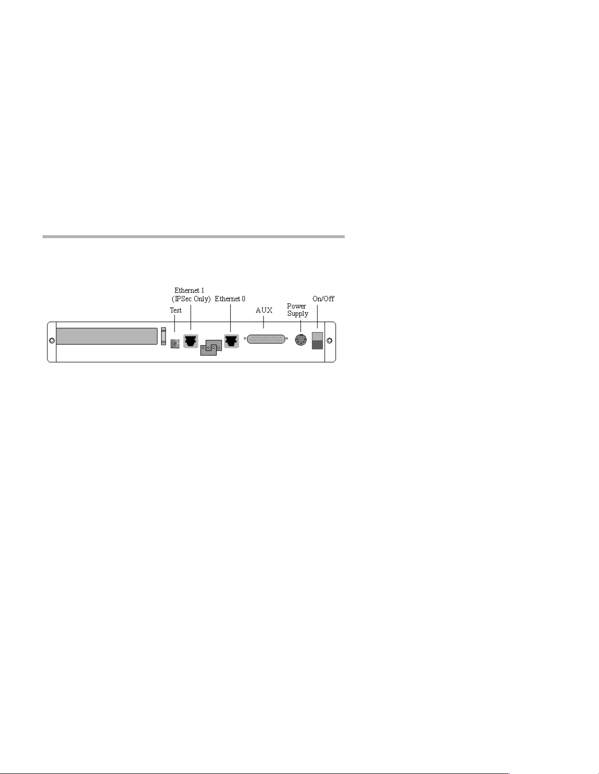
Chapter 3 - Network Installation
Figure 1. IntraPort 2/2+ VPN Access Server Back Panel
This section of the manual describes how to connect the IntraPort 2/2+
VPN Access Server to your Ethernet network. In summary , the steps for
installation are:
1. Make sure the server is powered down and not connected to any
power source .
2. Connect the server to the Ethernet network(s).
3. Connect a management console to the server (optional).
4. Plug in the power cable and power up the server.
Placing the Server
The IntraPort 2/2+ VPN Access Servers ar e meant to be left stand -alone
on a desktop or equipment table.
v
Note: When stacking other equipment on the IntraPort 2/2+, do not
exceed 25 pounds of evenly distributed weight on top of the device.
Additional weight may bend the case.
Connecting the Server to the Ethernet
Because Ethernet 1 is IPSec-only (meaning it will only handle IPSec
packets and will drop all other traffic), you need to pay special attention
to your Ethernet connection setup.
Ethernet 1 should only be used if you are planning to set the IntraPort
2/2+ to operate in parallel with your existing firewall. This is the recommended setup. In this scenario, Ethernet 1 should be connected to the
same Ethernet segment as y our Inter net gateway rout er while Et hernet 0
will serve as an IP, IPX and AppleTalk router port for your internal
networks.
Page 16

10 Chapter 3 - Network Installation
The other option is to set up the server behind your Internet access
router/firewall using Ethernet 0 only. In this scenario, Ethernet 1 is not
used and should not be plugged in to anything. You will also have t o set up
your firewall to allow IPSec traffic through (see the section on setting up
an IP Gateway for Ethernet 0 in Chapter 6 for more information).
The 10/100 Ethernet interfaces directly support full or half duplex
100BaseTx or 10BaseT twisted-pair Ethernet. To connect one of the
server’s Ethernet interfaces to twisted-pair Ethernet cabling, you will need
an unshielded twisted-pair station cable that is connected to a
10BaseT -compatible twisted-pair hub (for a transmit speed of 10 Mbps) or
a 100Mbps Fast Ethernet hub (for a transmit speed of 100 Mbps).
v
Note: Ethernet cables and cable connectors are not supplied with the
IntraPort 2/2+. Category 5 cabling is required for 100 BaseT operation. Please contact your reseller or your Compatible Systems sales
representative for information on obtaining the correct Ethernet
cabling supplies.
If your twisted-pair hub is already i n place, you can connect the server to
an active network without interrupting network activity. The server must
be powered off.
Simply plug an unshielded twisted-pair cable (that is already connected
to your 10BaseT-compatible or 10 0Ba seTx-compatible twisted-pair
hub) into the RJ-45 Ethernet connector on t he back of the unit.
Connecting a Management Console
If you wish to connect an out-of-band management console, use the
supplied cable and connect to the Console interface on the back of the
IntraPort 2/2+. You can use a dumb terminal or a computer equipped with
VT100 terminal emulation.
The default settings for the Console interface are VT100 terminal emulation, 9600 bps, 8 bits, no parity, 1 stop bit, and no Flow Control.
Powering Up the Server
Power up the server. At power-up, the server will tak e appr oximately one
minute to become visible to CompatiView.
v
Note: If you want to use Telnet as a management tool, you must first
configure an IP address into the server with either an out-of-band
console, CompatiView or a reconf igur ed IP h ost or wo rkstation on the
same Ethernet segment as the server. See Chapter 5 - Command Line
Management.
Page 17

Chapter 4 - CompatiView Software Installation 11
Chapter 4 - CompatiView Software Installation
All of the products in the Compatible Systems networking family,
including all IntraPort servers, RISC Router and MicroRouter models,
can be managed from a single management platform called
CompatiView. CompatiView is included on the CD-ROM which was
shipped with your IntraPort 2/2+ VPN Access Server. If your IntraPort
2/2+ is running software version 5.0 or later, then you must use
CompatiView version 5.3 or later. Earlier versions of CompatiView
will not be able to log into the server.
v
Note: An older version of CompatiView for Mac OS is also included
on the CD-ROM shipped with your server. The Mac OS version can
be used with other Compatibl e products such as MicroRoute rs and
RISC Routers; however, it is not compatible with the IntraPort
2/2+ VPN Access Server software. You must use CompatiView for
Windows, versions 5.0 or later, to manage your server with CompatiView. PC emulator software such as SoftWindows may be used
for this purpose, if your Macintosh supports it.
v
Note: Once you have installed CompatiView, you can find more
information on how to use it in the CompatiView Management
Software Reference Guide which was included with your server.
CompatiView for Windows
CompatiView for Windows allows you to man age the server from an
IBM-compatible PC running Windows95/98 or Windows NT. The PC
can either be configured as an IPX client on a Novell NetWare internet,
or as an IP WinSock client on an IP internet.
System Requirements
In order to successfully run CompatiView for Windows, you need:
• IBM PC or compatible w/ 486 or later processor
• Microsoft Windows95/98 or Windows NT (version 3.51 or later)
installed
• VGA or better monitor
• IP - A WinSock-compatible transport stack
- and/or -
• IPX - A Netware or Microsoft Client installation
Page 18

v Note: To choose the active transport protocol on a Windows machine
which has both IPX and IP installed, select “Options” from the
Database menu and click the General tab. Then select the appropriate radio button under “Transport.”
Installation and Operation
The Window s version of the CompatiView program can be found
in the Network Management/CompatiView/Windows directory on
the CD-ROM that was included with your IntraPort 2/2+ VPN
Access Server.
Run the auto-installation program (CV5x file) by double-clicking on it.
The installation program will ask you to select (or create) a directory in
which it should locate CompatiView and its associated files and database subdirectory.
Once the installation is complete, double click on the CompatiView
icon to open the program. For further information on using
CompatiView, see the CompatiView Management Software Reference
Guide included with your server.
v
Note: For an up-to-date description of the changes (if any) made to
Win dow s sys tem files by the instal lat ion program, see the
README.TXT file located in the CompatiView installation directory.
Transport Protocols and CompatiView
CompatiView will be able to use the transport protocol (IP or IPX) you
have selected to access Compatible Systems pr oducts anywhere on your
internetwork. Depending on your security setup, you may also be able
to use the IP transport option to manage devices across the Internet.
The IP protocol does not provide a method for CompatiView to automatically discover the IntraPort 2/2+ VPN Access Server. To initially
contact the server over IP using CompatiView, you must first enter a
valid IP address into the server. You can do this either on a console
directly connected to the server or by setting a workstation’s IP address
to 198.41.12.2 with a Class C subnet mask (255.255.255.0) so that it
can communicate over Ethernet with 198.41.12.1 (the shipping default
of Ethernet 0). After setting the server’s IP address, be sure to change
the workstation’s configuration back to its original settings.
The IPX protocol does
the server. Compatible Systems devices are configured to autoseed the
allow CompatiView to automatically discover
Page 19

Chapter 4 - CompatiView Software Installation 13
two most common IPX frame types upon startup (802.2 and 802.3
(raw)). If CompatiView has the IPX/SPX protocol selected as its transport, it will be necessary to either powerup the server before powering
up the workstation, or reboot the workstation after the server has
completed its boot sequence. This process will ensure that the workstation and the server have the proper IPX network bindings for communication.
For more information on using CompatiView management software to
configure your server, see Chapter 6 - Basic Configuration Guide.
Page 20

.
Page 21

Chapter 5 - Command Line Management 15
Chapter 5 - Command Line Management
The command line interface allows you to configure and monitor the
server in-band via Telnet or out-of-band with a terminal connected to
the server’s Console interface.
v
Note: Proper syntax is vital to effective operation of command line
management. Case is not significant – you may enter commands in
upper case, lower case, or a combination of the two.
Out-of-Band Command Line Management
You can use command line management and text-based configuration
out-of-band as a per manent management method, o r only t emporarily in
order to set the server’s IP parameters to allow in-band Telnet access.
In order to access the command line out-of-band, do the following:
1. Set a terminal or a PC equipped with VT100 terminal emulation to
a baud rate of 9600, 8 bits, no parity, 1 stop bit and no Flow Control.
2. Connect it to the server’s Console interface using the cable which
was supplied with the IntraPort 2/2+.
3. Press the <Return> key one or two times.
4. Enter the default password letmein at the password prompt. The
command line interface prompt will appear on the screen.
If you plan to use out-of-band access for ongoing management of your
server, you can find further information on configuring your server in
Chapter 6 - Basic Configuration using Command Line. Otherwise, see
the section later in this chapter on Setting Up Telnet Operation for
information on setting the server to allow Telnet access from hosts on
its network.
Page 22

Temporarily Reconfiguring a Host for Command Line Management
You can temporarily reconfigure an IP host in order to set the server’s
IP parameters to allow in-band Telnet access.
If you wish to set the server’s basic IP parameters in this fashion, the
host must be on the same Ethernet segment as the IntraPort’s server’s 0
interface. You can then do the following:
1. Set the host’s IP address to 198.41.12.2, with a Class C subnet
mask (255.255.255.0) and then Telnet to 198.41.12.1.
2. Enter the default password letmein at the password prompt. The
command line interface prompt will appear on the screen.
3. Use the configure command and set the IPAddress, SubnetMask,
and IPBroadcast keywords in the IP Ethernet 0 section.
4. Use the save command to save the changes to the device’s
Flash ROM.
5. Change the ho st’s configuration back to its original settings.
See the next section (Setting Up Telnet Operation) for information on
setting the server to allow Telnet access from hosts on its network.
Setting Up Telnet Operation
Telnet is a remote terminal communications protocol based on
TCP/IP. With Telnet you can log into and manage the IntraPort 2/2+
from anywhere on your IP i ntern etwo rk, in cludi ng acro ss the In t ernet
if your security setup allows it.
To manage the server with Telnet, you must:
1. Run Telnet client software on your local computer, which will
communicate with the Telnet server built into the IntraPort 2/2+.
2. You must also set some basic IP parameters in the server. The
required parameters for Telnet access to an interface are the IP
address, IP subnet mask, and IP broadcast address. There are several ways to set them.
• You may set them using text-based configuration either
out-of-band via the Console interface or in-band via a reconfigured IP host. Instructions for setting up these two methods
were given earlier in this chapter. Once you have set up the
Page 23

Chapter 5 - Command Line Management 17
command line interface, do the following:
A. Use the configure command and set the IPAddress, Sub-
netMask, and IPBroadcast keywords in the
IP Ethernet 0 section.
B. Use the save command to save the changes to the device’s
Flash ROM.
• You may also use CompatiView from a reconfigured IP host
(if using the IP transport protocol), or anywhere on your network (if using the IPX transport protocol). Instructions for
these two methods are given in Chapter 4 - CompatiView Soft-
ware Installation.
With CompatiView, basic IP parameters can be set using the
TCP/IP Routing: Ethernet 0:0 dialog box. Use the Save
to/Device option under the File menu to save the changes.
After you have set these IP parameters and saved the changes, you can
use Telnet to access the server from any node on your IP network.
Invoke the Telnet client on your local host with the IP address of the
server you wish to manage.
For more information on using Text-Based Configuration and
Command Line Management to configure your server, see Chapter 6 -
Basic Configuration Guide.
Page 24

.
Page 25

Chapter 6 - Basic Configuration Guide 19
Chapter 6 - Basic Configuration Guide
This chapter provides a step-by-step outline of the minimum required
parameters which must be configured into the device for proper operation. Detailed information on the meaning of the server’s parameters is
provide d i n the CompatiView Management Software Reference Guide
and the Text-Based Configuration and Command Lin e Management
Reference Guide. You should use this list as a starting point to look up
more specific information in the other documents.
There are a number of settings which are optional, in the sense that they
are not required for all installations. These settings are not covered in
this chapter.
v
Note: This Basic Con f iguration Guide doe s no t include information
on setting up packet filters. See the CompatiView Management
Software Reference Guide regarding IP, IPX and AppleTalk
packet filters for more information. Refer to the VPN Client Refer-
ence Guide for information on the installation and operation of the
VPN Client sof t ware
Setup Options
The IntraPort 2/2+ can be set up in two different ways. The recommended setup is to use both Ethernet ports so that it operates in parallel
with your existing firewall or proxy server and serves as the IPSec
component of your security system. In this setup, Ethernet 0 serves as
an IP, IPX and AppleTalk router port, while Ethernet 1 receives and
sends only IPSec packets. The other option is to set up th e server behind
your Internet access router/firewall using Ethernet 0 only. This guide
includes basic instructions for both setups.
Page 26

20 Chapter 6 - Basic Configuration Guide
Diagram of Dual-Ethernet Setup
Figure 2. Diagram of Dual-Ethernet Setup
Page 27

Chapter 6 - Basic Configuration Guide 21
Diagram of Single-Ethernet Setup
Figure 3. Diagram of Single Ethernet Setup
Page 28

22 Chapter 6 - Basic Configuration Guide
Configuration Using CompatiView
This section provides a list of parameters that must be entered into a
server for proper operation using CompatiView, Co mpatible Systems’
management software. If you wish to use the command line interface to
configure the server, see the next section in this chapter, Basic Configu-
ration Using Command Line.
VPN Client Tunnel Settings
Configuration of the server for both dual and single Ethernet setups is
very similar, but when there are differences between them, the appropriate step for each setup is indicated.
v
Note: Remember that in single Ethernet setups, Ethernet 1 must not
be connected to anything or else it may cause difficult to diagnose
problems on the IntraPort 2/2+ a nd on your network.
1. Turn off AppleTalk and IPX (optional).
If you are using AppleTalk and/or IPX, you can either leave the default
configuration parameters in place or see Chapter 7 for more information
on configuring those protocols. If you are not using AppleTalk and/or
IPX:
A. Cl ick on the Apple Talk Routing protocol branch under Ether-
net 0. In the AppleTalk Routing dialog box select the Phase 2
Off radio button.
B. Click on the IPX Routing pr ot oco l bran ch un der Et hern et 0. In
the IPX Routing dialog box select the IPX Off radio button
C. Click OK.
Page 29

Chapter 6 - Basic Configuration Guide 23
2. Set basic IP parameters for Ethernet 0.
Dual Ethernet Single Ethernet
TCP/IP Routing: Ethernet 0
To access this dialog box, select T CP/IP Routing under Eth ernet 0 in th e
Device View.
A. Click the IP Routing radio button.
B. Enter the internal TCP/IP address you have assigned the
IntraPort 2/2+. Verify that you have the IP Address, the Net-
work IP Subnet Mask and the Network IP Broadcast Mask
correctly entered. Incorrect information can cause difficult to
diagnose problems or disable the IntraPort until the information is corrected.
C. If you are using RIP, select the correct version from the Rout-
ing Protocol pull-down menu. If you are not, select None in
the Routing Protocol pull-down menu.
v
Note: Routing protocol options, OSPF, and all parameters under the
Options button are advanced configuration parameters and are not
covered here. Refer to the CompatiView Management Software
Reference Manual for more information.
D. Click OK.
Page 30

24 Chapter 6 - Basic Configuration Guide
3. (Dual Ethernet) Set basic IP parameters for Ethernet 1.
TCP/IP Routing: Ethernet 1
T o access this dialog box , select TCP/IP Routing under Ether net 1 in the
Device View.
A. Click the IP On radio button.
B. Enter the external TCP/IP address you have assigned the
IntraPort 2/2+. This address must not be in the same TCP/IP
network as Ethernet 0 or you w i ll disable TCP/IP in the
IntraPort 2/2+. Verify that you have the IP Address, the Net-
work IP Subnet Mask and the Network IP Broadcast Mask
correctly entered.
C. Click OK.
3. (Single Ethernet) Turn IP off on Ethernet 1.
IP Connection: Ethernet 1
T o access this dialog box , select TCP/IP Routing under Ether net 1 in the
Device View.
A. Click the IP Off radio button.
B. Click OK.
Page 31

Chapter 6 - Basic Configuration Guide 25
4. Set an IP Gateway for Ethernet 0.
IP Static Routes
To access the IP Static Routes dialog box, select IP Static Routes under
Global in the Device View.
A. Click the Add... button. The Static Route dialog box will
appear:
Dual Ethernet Static Route Single Ethernet Static Route
B. Click the IP Address radio button in the Gateway section.
For dual Ethernet setups, enter the internal TCP/IP address of
your firewall or proxy, whichever is applicable.
For single Ethernet setups, enter the internal TCP/IP address
of your upstream Internet access/firewalling router.
In either case, this address must be on the same TCP/IP network as the Ethernet 0 address of the IntraPort 2/2+.
Page 32

26 Chapter 6 - Basic Configuration Guide
Leave all other parameters at their default settings for basic
configuration, or refer to the CompatiView Management Soft-
ware Ref erence Guide for more advanced configuration settings.
v
Note: For single Ethernet setups, you must configu re the firewall to
allow
:
•UDP port 500 (ISAKMP)
•Protocol number 51, which is the AH (Authentication
Header) protocol packet type
- and/or -
•Protocol number 50, which is the ESP (Encapsulating Security Payload) protocol packet type
C. Click OK.
Page 33

Chapter 6 - Basic Configuration Guide 27
5. Set an IPSec Gateway.
IPSec Gateway
To access this dialog box, select IPSec Gateway under Global in the
Device View.
A. For dual Ethernet setups, the IPSec Gateway is the equivalent
of a default gateway for the IPSec interface (Ethernet 1). Enter
the TCP/IP address of the upstream or Internet router for your
network. This must be an address on the same TCP/IP net work
as the Ethernet 1 address of the IntraPort 2/2+.
For single Ethernet setups, the IPSec Gateway is an optional
setting. It serves as a default gateway for all IPSec (i.e., tunneled) traffic. Enter the TCP/IP address of your Internet
access/firewalling router. This must be an address on the same
TCP/IP network as the Ethernet 0 address of the IntraPort
2/2+.
B. Click OK.
Page 34

28 Chapter 6 - Basic Configuration Guide
6. Set an IKE Policy.
There are two phases to the IKE negotiation. During Phase 1 negotiation, the IntraPort and Client must authenticate each other. The IKE
Policy dialog box con t rols t his P has e 1 n ego tiat ion . P has e 2 nego t iatio n
involves the setup of an individual tunnel connection and is controlled
by the VPN Group Configuration, documented in Step 7.
IKE Policy
T o access this dialog b ox, s elect IKE Policy un der Glob al in the Device
View.
These parameters specify a protection suite for the IKE negotiation
between the IntraPort server and client. There are three pieces to the IKE
protection suite.
1. The first piece of each option is the authentication algorithm to be
used for the negotiation. MD5 is the message-digest 5 hash algorithm. SHA is the Secure Hash Algorithm, which is considered to be
somewhat more secure than MD5.
2. The second piece is the encryption algorithm. DES (Data Encryption Standard) uses a 56-bit key to scramble the data. 3DES uses
three different keys and three applications of the DES algorithm to
scramble the data.
3. The third piece is the Diffie-Hellman group to be used for key
exchange. Because larger numbers are used by the Group 2 (G2)
algorithm, it is more secure than Group 1 (G1).
A. You can specify one or more protection suites by checking as
many of the boxes as you wish, or leave the default setting.
B. Click OK.
Page 35

Chapter 6 - Basic Configuration Guide 29
7. Set up VPN Group Configurations.
VPN Group Configuration: General Tab
To access this dialog box, select VPN Group Configuration in the
Device View.
A. Click on the New... button.
B. Enter a New VPN Group Config Name (e.g. Sales, Account-
ing, etc.) in the pop-up box.
C. Click OK. You are now ready to enter group parameters.
D. On the General Tab:
• Leave the Bind To pull-down menu set to Ethernet 0. You
may change this value later, but that is an advanced configuration parameter and not covered here. The Bind To
specifies which interface on the device will act as the local
end point for tunnels defined by this configuration.
• Choose the Max Connections value and keep this number
in mind. This number is the maximum number of concurrent Client sessions allowed in this VPN Group Confi guration.
• Set a different Keep Alive Interval or leave the default
value. This is the number of seconds bet ween keep-alive
packets sent to each connected client by the device.
• Set a different Inactivity Timeout or leave the default
value. This is the number of seconds the device will wait
Page 36

30 Chapter 6 - Basic Configuration Guide
without receiving any traffic from a client belonging to
this VPN Group Configuration without ending the tunnel
session.
• Set the Minimum Client Version or keep the default
value. This places a limit on the VPN Client Software version number which will be allowed to connect.
Leave all other parameters at their default settings for basic
configuration, or refer to the CompatiView Management Soft-
ware Ref erence Guide for more advanced configuration settings.
VPN Group Configuration: IKE Configuration Tab
E. On the IKE Configuration Tab, select the authenti cation and
encryption algorithms to be used for tunnel sessions.
v
Note: STEP/STAMP (Compatible System’s proprietary tunnel negoti-
ation prot ocol) en cryption pa rameters may be set u sing the M anual
Tab. This can be used to allow connections from users running
older versions of the VPN Client soft ware, but is not recommended
for other VPN Groups.
• Click on the Add... button in the Transform section to access
the IKE Configuration Transform List dialog box:
Page 37

Chapter 6 - Basic Configuration Guide 31
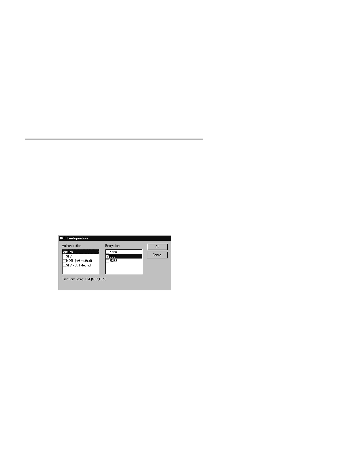
IKE Configuration Transform List
The default settings of MD5 for Authentication and DES for
Encryption are adequate for most setups. Click OK.
• In the IKE Key Management dialog box, yo u may click on the
PFS checkbox to add additional security parameters during
tunnel sessions. (This is optional.)
v
Note: For more information regarding encryption, authentication,
and Perfect Forward Secrecy, refer to the CompatiView Manage-
ment Software Reference Guide
Page 38

32 Chapter 6 - Basic Configuration Guide
Dual Ethernet VPN Group Configuration: IP Connection Tab
Single Ethernet VPN Group Configuration: IP Connection Tab
F. On the IP Connection Tab:
• Enter the Start IP Addre ss. This specifies the first IP
address to be assigned to client sessions under this configuration. This address will be incremented by one for each
new client session, until the Max Connections number
(entered on the General tab) is reached. Since the Max
Connections value is 30 for this VPN Group, then the
Start IP Address must be t he first in a block of at least 30
unused IP addresses.
For this very basic setup, it is recommended that these
addresses be on the internal TCP/IP network (i.e., on the
Page 39

Chapter 6 - Basic Configuration Guide 33
same network as Ethernet 0 or a subinterface thereof).
Also, they cannot conflict with those used for any other
VPN Groups.
v
Note: For large numbers of users (i.e., over 50), it’s
recommended that the block of addr esses be specified as a Loca l IP
Net because address administration is easier. Using a Start IP
Address is recommended for smaller numbers of users because the
routing setup is simpler. See the
CompatiView Management
Software Reference Guide for more information on the difference
between the Start IP Address and the Local IP Net.
• Click the Add... button in the Allow Connections to area.
An Add IP Address pop-up box will appear. THIS IS A
VERY IMPORTANT FIELD. The values you enter here
determine what TCP/IP traffic is tunneled, or, more commonly, where a client who belongs to this VPN Group
Configuration can go on your network. If you enter the
internal network (in the dual Ethernet example,
192.168.233.0/24), all traffic from a client going to the
internal network will be tunneled through the IntraPort
2/2+.
This is the most common configuration.
As a special case, the entry 0.0.0.0/0 will send all IP traffic
through the tunnel, although the Exclude Local LAN from
Tunnel checkbox on the General tab can still be used to
exclude LAN traffic if desired.
There can be multiple entries, including individual
addresses (i.e. hosts).
G. If you will not be tunneling IPX traffic, you are done with the
VPN Group configuration. Click OK and skip to the VPN
User Configuration section.
Page 40

34 Chapter 6 - Basic Configuration Guide
VPN Group Configuration: IPX Connection Tab
H. If you will be tunneling IPX traffic, click the IPX Connection
Tab.
• Enter an IPX network number in the Start IPX Network
edit box. This IPX network number is the first IPX
address assigned to an incoming Client tunnel session.
The Start IPX Network also works with the Max Con-
nections value, which means you must have at least 30
consecutive unused IPX addresses available. The IPX network number entered here must not be the same network
number as any other IPX network on your network and
you must choose a network nu mber which will not overlap
as Client sessions are established. In this example, the first
client to connect will be assigned the IPX network
CAFEB00. The next client which connects concurrently
will be assigned the IPX network CAFEB01, and so on.
Leave all other parameters at their default settings for basic
configuration, or refer to the CompatiView Management Soft-
ware Ref erence Guide for more advanced configuration settings.
I. You may repeat Step 6 as needed to add all groups. When
you are finished adding groups, click OK.
Page 41

Chapter 6 - Basic Configuration Guide 35
8. Set up VPN Users.
If you are using a RADIUS server for user authentication, you will need
to set up VPN users on that server. If not, then you must enter each user
into the VPN User database. Bear in mind that the values for each user
must be identical in the VPN Client configuration on the remote computer.
VPN User Configuration
T o access this d ialog box, select VPN User Configuration in the Device
View.
A. Click the Add... button. The following dialog box will appear:
VPN User
B. Enter the user name in the Name field. This name can be any-
thing within reason but cannot exceed 60 ASCII characters.
The VPN Group specifies the VPN Group to which this user
belongs. Select the VPN Group using the pull-down menu.
The IKE Shared Key is the secret used to generate session
keys to authenticate and/or encrypt each packet received or
Page 42

36 Chapter 6 - Basic Configuration Guide
sent. This secret is used for VPN using IKE Key Manag ement.
The same secret must also be entered into the V PN Client for
the tunnel session to be successful.
v
Note: STEP/STAMP is Compatible System’s proprietary tunnel nego-
tiation protocol. It can be used to allow connections from users
running older versions of the VPN Client software, but is not recommended for new users and is not covered here.
C. Click OK. You may repeat Step 8 as needed to add all
users.
9. Save the configuration to a file and download to the device.
A. From the File menu choose Save T o > File. This will bring up
a file save dialog box. Name the device configuration file,
making sure that you associate the file nam e with the IntraPort
2/2+ and can find the file later.
B. From the File menu choose Save To > Device. This will bring
up a download configuration dialog window. Choose the
IntraPort 2/2+ if given the option. When asked if you are sure
that you want to download the configuration and restart the
device, click on the Yes button. You should see a new window
with a log of the download process. CompatiView will then
tell you that the download is complete and the device is rebooting. Do not turn the IntraP ort 2/2+ of f during the boot pro cess.
After the IntraPort has rebooted, users will be able to connect
with the VPN Client software.
Page 43

Chapter 6 - Basic Configuration Guide 37
Configuring the Server for LAN-to-LAN Tunnels
This section configures VPN tunn el parameters and defines a virtual port
for LAN-to-LAN tunnel traffic. It assumes that you have already
assigned IP addresses to the Ethernet interface(s), and set up static
routes, as shown in VPN Client Tunnel Settings.
v
Note: VPN Ports are only used for LAN-to-LAN tunnels. VPN Client
tunnels do not use VPN Ports. LAN-to-LAN tunneling requir es that
you set parameters for a VPN port on each end of a tunnel, so you
must repeat the following steps on the remote end.
1. Add a VPN Port
A. From the File menu, choose VPN Port> Add VPN Port. This
will bring up the Add VPN Port dialog box and will allow you
to select a number for the virtual port.
Add VPN Port
B. Click OK
2. Set up the Tunnel Partner
Once you have created a VPN port, you need to provide information
about the remote Tunnel Partner and specify which interface on the local
device will act as the endpoint for the tunnel.
A. In the Device View , click on the VPN port icon that was added
in the previous step, and select Tunnel Partner. This will open
the Tunnel Partner: VPN (#) dialog box.
Tunnel Partner: VPN (#)
B. Enter the Partner Address. This is the IP address of the
remote Tunnel Partner with which this VPN port will communicate via the tunnel. This will be an interface on the remote
router which has been set to route IP and will also be the
remote VPN port’s Bind To interface.
Page 44

38 Chapter 6 - Basic Configuration Guide
C. If you are using both Ethernet ports, then the Bind To interface
should be set to Ethernet 1. For single Ethernet setups, it
should be Ethernet 0. This specifies which interface on this
device will act as the end point for the tunnels defined by this
configuration. Packets sent from this device to the r emote Tunnel Partner will use this interface’s IP address as a source
address.
D. Click OK.
3. Set up Key Management
These settings control how the local Tunnel Partner will identify and
authenticate the remote Tunnel Partner. IKE Key Management is
recommended.
IKE Key Management
Once a VPN port has been created, you may access the IKE Key
Management dialog box by clicking on the port’s icon in the Device
View and sel ecting IKE Key Management.
A. From the pull-down me nu, select th e Key Manage method to
use for this tunnel.
If Auto key management is selected, IKE will be used to allow
two devices to negotiate between themselves which encr yption
and authentication methods will be used for the tunnel.
If Manual is selected, this Tunnel Partn er wi ll not u se IKE,
and the tunnel’s encryption and authentication parameters
must be manually set in the Manual Key Management dialog
box, which is not described in this guide.
If Initiate is selected, this Tunnel Partner will use IKE, but
Page 45
Chapter 6 - Basic Configuration Guide 39
will only initiate tunnel establishment attempts and will not
respond to th em.
If Respond is selected, this Tunnel Partner will use IKE, but
will only respond to tunnel establishment attempts and will not
initiate them.
B. Enter the Shared Key. This is a shared alphanumeric secret
that is used to generate session keys.
C. Select the authentication and encryption algorithms to be used
for tunnel sessions us i ng t he I KE Co nfi g urat ion Transform list
box.
Click on the Add... button in the Transform section to access
the IKE Configuration Transform List dialog box.
IKE Configuration Transform List
The default settings of MD5 for Authentication and DES for
Encryption are adequate for most setups. Click OK.
D. In the IKE Key Management dialog box, you may click on the
PFS checkbox to add additional security parameters during
tunnel sessions. (This is optional.)
v
Note: For more information regarding encryption, authentication,
and Perfect Forward Secrecy, refer to the CompatiView Management
Software Reference Guide .
E. Click OK.
Page 46

40 Chapter 6 - Basic Configuration Guide
4. Save the configuration to a file and download to the device.
A. From the File men u choose Save To > File. This will bring up
a file save dialog box. Name the device configuration file,
making sure that you associate the file nam e with the IntraPort
2/2+ and can find the file later.
B. From the File menu choose Save To > Device. This will bring
up a download configuration dialog window. Choose the
IntraPort 2/2+ if given the option. When asked if you are sure
that you want to download the configuration and restart the
device, click on the Yes button. You should see a new window
with a log of the download process. CompatiView will then
tell you that the download is complete and the device is rebooting. Do not turn the IntraP ort 2/2+ of f during the boot pro cess.
After the IntraPort has rebooted, LAN-to-LAN tunnels can be
established.
Page 47

Chapter 6 - Basic Configuration Guide 41
Basic Configuration Using Command Line
This section briefly discusses the major parameters that must be set in
order to use the IntraPort 2/2+ VPN Access Server u sing co mmand line
management or text-based configuration, either out-of-band (through
the server’s Console interface) or in-band through Telnet.
Detailed information on the meaning of the server’s parameters is
provided in the Text-Based Configuration and Command Line
Management Reference Guide. You should use this list as a starting
point to look up more specific information in other documents.
If you wish to use CompatiView, Compatible Systems’ management
software to configure the server, see the previous section in this chapter ,
Configuration using CompatiView.
VPN Client Tunnel Settings
Configuration of the server for both dual and single Ethernet setups is
very similar, but when there are differences between them, the appropriate step for each setup is indicated.
v
Note: Remember that in single Ethernet setups, Ethernet 1 must not
be connected to anything or else it may cause difficult to diagnose
problems on the IntraPort 2/2+ a nd on your network.
1. Turn off AppleTalk and IPX (optional).
If you are using AppleTalk and/or IPX, you can either leave the default
configuration parameters in place or see Chapter 7 for more information
on configuring those protocols. If you are not using AppleTalk and/or
IPX, use configure and set the Mode keyword to Off.
Example
config AppleTalk Ethernet 0
[ AppleTalk Ethernet 0 ] # mode=off
config IPX Ethernet 0
[ IPX Ethernet 0 ] # mode=off
Page 48

42 Chapter 6 - Basic Configuration Guide
2. Set basic IP parameters for Ethernet 0.
This will be the internal TCP/IP addressing information you have
assigned to the IntraPort 2/2+
Use configure and set the IPAddress, SubnetMask, and IPBroadcast
keywords in the IP Ethernet 0 section.
Dual Ethernet Setup Example
config IP Ethernet 0
[ IP Ethernet 0 ] # ipaddress=192.168.233.1
[ IP Ethernet 0 ] # subnetmask=255.255.255.0
[ IP Ethernet 0 ] # ipbroadcast=192.168.233.255
Single Ethernet Setup Example
config IP Ethernet 0
[ IP Ethernet 0 ] # ipaddress=206.45.55.1
[ IP Ethernet 0 ] # subnetmask=255.255.255.0
[ IP Ethernet 0 ] # ipbroadcast=206.45.55.255
3. (Dual Ethernet) Set basic IP parameters for Ethernet 1.
Enter the external TCP/IP address you have assigned the IntraPor t 2/2+.
This address must not be in the same TCP/IP network as Ethernet 0 or
you will disable TCP/IP in the IntraPort 2/2+.
Use configure and set the IPAddress, SubnetMask, and IPBroadcast
keywords in the IP Ethernet 1 section.
Example
config IP Ethernet 1
[ IP Ethernet 1 ] # ipaddress=206.45.55.1
[ IP Ethernet 1 ] # subnetmask=255.255.255.0
[ IP Ethernet 1 ] # ipbroadcast=206.45.55.255
3. (Single Ethernet) Turn IP off on Ethernet 1.
Because you have only one Ethernet port, you will not be using Ethernet
1, which is the IPSec only port. Disable the port for Ethernet 1 here.
Use configure and set the Mode keyword in the IP Ethernet 1 section.
Example
config IP Ethernet 1
[ IP Ethernet 1 ] # mode=off
Page 49

Chapter 6 - Basic Configuration Guide 43
4. Set an IP Gateway for Ethernet 0.
For dual Ethernet setups, this is the internal T CP/IP address of your
firewall or proxy, whichever is applicable. For single Ethernet setups,
this is the internal TCP/IP address of your upstream Internet
access/firewalling router. In either case, this address must be on the
same TCP/IP network as the Ethernet 0 address of the IntraPort 2/2+.
Use edit config to modify th e IP Static section. Configuration lines in
this section have the following format:
<Destination><Mask><Gateway/Port><Metric>[<Redist=(RIP|none)>]
Dual Ethernet Setup Example
Edit [ IP Static ]> append 1
Enter lines at the prompt. To terminate input, enter
a . on a line all by itself.
Append> 0.0.0.0 0.0.0.0 192.168.233.3 1 redist=none
Append> .
Edit [ IP Static ]> exit
Single Ethernet Setup Example
Edit [ IP Static ]> append 1
Enter lines at the prompt. To terminate input, enter
a . on a line all by itself.
Append> 0.0.0.0 0.0.0.0 206.45.55.2 1 redist=none
Append> .
Edit [ IP Static ]> exit
v Note: For single Ethernet setups, you must configure the firewall to
allow
:
•UDP port 500 (ISAKMP)
•Protocol number 51, which is the AH (Auth entication Header)
protocol packet type
- and/or -
•Protocol number 50, which is the ESP (Encapsulating Secu-
rity Payload) protocol packet type
Page 50

44 Chapter 6 - Basic Configuration Guide
5. Set an IPSec Gateway.
For dual Ethernet setups, the IPSec Gateway is the equivalent of a
default gateway for the IPSec interface (Ethernet 1). Enter the TCP/ IP
address of the upstream or Internet router for your network. This must
be an address on the same TCP/IP network as the Ethernet 1 address of
the IntraPort 2/2+.
For single Ethernet setups, the IPSec Gateway is an optional setting. It
serves as a default gateway for all IPSec (i.e., tunneled) traffic. Enter
the TCP/IP address of your Internet firewalling router. This must be an
address on the same TCP/IP network as the Ethernet 0 address of the
IntraPort 2/2+.
Use configure and set the IPSecGateway keyword in the General
section.
Example
configure general
[ General ] # ipsecgateway = 206.45.55.2
6. Set an IKE Policy.
There are two phases to the IKE negotiation. During Phase 1 negotiation, the IntraPort and Client must authenticate each other. The IKE
Policy section controls this Phase 1 negotiation. Phase 2 negotiation
involves the setup of an individual tunnel connection and is controlled
by the Transform keyword in the VPN Group Name section, docu-
mented in Step 7.
Use configure and set the Protection keyword in the IKE Policy section.
The Protection keyword specifi es a protection suite for the IKE negotiation between the IntraPort server and client.
Example
configure IKE Policy
[ IKE Policy ]# protection=md5_des_g1
Page 51

Chapter 6 - Basic Configuration Guide 45
7. Set up VPN Group Configurations.
This is where tunneling profiles for a group of one or more IntraPort
2/2+ users are defined.
Use configure VPN Group Name to create a VPN Group section and
set the following keywords in the section you just created:
BindTo-Specifies which interface on the device will act as the
local end point for the tunnels defined by this configuration.
MaxConnections-Used to limit the number of client connections
for this VPN Group configuration.
StartIPAddress-Specifies the first IP address to be assigned to cli-
ent sessions under this configuration. This address will be
incremented by one for each new client session, until the Max-
Connections value is reached. Since the MaxConnections
value is 30 for this VPN Group, then the StartIPAddress must
be the first in a block of at least 30 unused IP addresses.
For this very basic setup, it is recommended that these
addresses be on the internal TCP/IP network (i .e., on t he s ame
network as Ethernet 0 or a subinterface thereof). Also, they
cannot conflict with those used for any other VPN Groups.
v
Note: For large numbers of users (i.e., over 5 0), it’s recommended
that the block of addresses be specified as a Local IP Net because
address administration is easier. Using a Start IP Address is
recommended for smaller numbers of users because the routing
setup is simpler. See the
Text-Based Configuration and C ommand
Line Management Reference Guide for more information on the
difference between the StartIPAddress and the LocalIPNet.
LocalIPXNet-Specifies the first IPX address assigned to an incom-
ing Client tunnel session. The LocalIPXNet also works with
the MaxConnections value, which means you must have at
least 30 consecutive unused IPX addresses available. The IPX
network nu mber entered here must not be the same network
number as any other IPX network on your network and you
must choose a network number which will not overlap as Client sessions are established. In this example, the first cl ient to
connect will be assigned the IPX network CAFEB00. The next
client which connects concurrently will be assigned the IPX
network CAFEB01, and so on.
IPNet-Specifies a range of IP addresses which will be reachab le by
clients using this configuration. THIS IS A VERY IMPORT ANT SETTING. I f you enter the in ternal network ( in the dual
Page 52

46 Chapter 6 - Basic Configuration Guide
Ethernet example, 192.168.233.0/24), all traffic from a client
going to the internal network will be tunneled through the
IntraPort 2/2+. This is the most common configuration. There
can be multiple entries, including individual addresses (i.e.
hosts).
As a special case, the entry 0.0.0.0/0 will send all IP traffic
through the tunnel, although the ExcludeLocalLAN keyword
can still be used to exclude LAN traffic if desired.
Transform-Specifies the protection types and algorithms to be
used for client sessions.
v
Note: STEP/STAMP (Compatible System’s proprietary tunnel negoti-
ation protocol) encryption param eters may be set us i ng the
EncryptMethod keyword. This can be used to allow connections
from users running older versions of the VPN Client software, but
is not recomm ended for oth er VPN Groups and is not covered here.
Dual Ethernet Setup Example
configure vpn group "basic vpn config"
Section ’vpn group basic vpn config’ not found in the config.
Do you want to add it to the config? y
Configure parameters in this section by entering:
<Keyword> = <Value>
To find a list of valid keywords and additional help enter "?"
[ VPN Group “basic vpn config” ] # bindto=ethernet 0
[ VPN Group “basic vpn config” ] # maxconnections=30
[ VPN Group “basic vpn config” ] # startipaddress=192.168.233.50
[ VPN Group “basic vpn config” ] # localipxnet=CAFEBOO
[ VPN Group “basic vpn config” ] # ipnet=192.168.233.0/24
[ VPN Group “basic vpn config” ] # transform=ESP(MD5,DES)
Single Ethernet Setup Example
configure vpn group "basic vpn config"
Section ’vpn group basic vpn config’ not found in the config.
Do you want to add it to the config? y
Configure parameters in this section by entering:
<Keyword> = <Value>
To find a list of valid keywords and additional help enter "?"
[ VPN Group “basic vpn config” ] # bindto=ethernet 0
[ VPN Group “basic vpn config” ] # maxconnections=30
[ VPN Group “basic vpn config” ] # startipaddress=206.45.55.50
[ VPN Group “basic vpn config” ] # localipxnet=CAFEBOO
[ VPN Group “basic vpn config” ] # ipnet=206.45.55.0/24
[ VPN Group “basic vpn config” ] # transform=ESP(MD5,DES)
Page 53

Chapter 6 - Basic Configuration Guide 47
8. Set up VPN Users.
Users are added to the configuration by entering a few unique parameters, and each is assigned to a VPN Group Configuration, configured in
the previous step.
Use edit config to set the parameters in the VPN Users section. All
values are case sensitive.
Example
Edit [ VPN Users ] > append 1
Enter lines at the prompt. To terminate input, enter a . on a line
all by itself.
Append> Rumi Config=basic group config SharedKey=”shish” Auth=”Burnt”
Encrypt=”Kabob”
Append>
Edit [ VPN Users] exit
v Note: The Auth and Encrypt keywords specify STEP/STAMP (Com-
patible System’s proprietary tunnel nego t iat ion protocol) parame-
ters for users. These can be used to allow connections from users
running older versions of the VPN Client software, but is not recommended for new users.
9. Save the Configuration and download it to the device.
Use the save command to save the configuration and download it to the
device. When asked if you are sure that you want to download the
configuration and restart the device, reply yes. After the IntraPort has
rebooted, users will be able to connect with VPN Client software.
v
Note: Do not turn the Intr aPort 2/ 2+ off during t he boot process or it
will lose its operating software.
Example
IntraPort2 # save
Save configuration to flash and restart device? y
Page 54

48 Chapter 6 - Basic Configuration Guide
Configuring the Server for LAN-to-LAN Tunnels
This section configures VPN tunn el parameters and defines a virtual port
for LAN-to-LAN tunnel traffic. It assumes that you have already
assigned IP addresses to the Ethernet interface(s), and set up static
routes, as shown in VPN Client Tunnel Settings.
v
Note: VPN Ports are only used for LAN-to-LAN tunnels. VPN Client
tunnels do not use VPN Ports. LAN-to-LAN tunneling requires that
you set parameters for a VPN port on each end of a tunnel, so you
must repeat the following steps on the remote end.
1. Add a VPN Port.
Use the configure command to add a VPN Port.
Example
configure VPN Port 0
VPN Port(0) does not exist, do you wish to add it to the
config? y
2. Set up the Tunnel Partner.
Once you have created a VPN port, you need to provide some information about the remote Tunnel Partner and specify how tunnels will be s et
up.
Use configure and set keywords in the Tunnel Partner VPN port
number section (thi s will be the number of the port you just created).
Partner-Specifies the IP address of the remo te Tunnel Partner with
which this VPN port will communicate via the tunnel. This
will be an interface on the remote router which has been set to
route IP and will also be the remote VPN port’s BindTo inter-
face.
BindTo-This specifies which interface on this device will act as the
end point for the tunnels def ined by this conf iguratio n. Packets
sent from this device to the remote Tunnel Partner will use this
interface's IP address as a source ad dress. If you ar e using both
Ethernet ports, then the BindTo interface should be set to
Ethernet 1. For single Ethernet setups, it should be Ethernet 0.
KeyManage-Sets how the tunnel will be set up.
If Auto key management is specified, IKE will be used to
allow two devices to negotiate between themselves which
encryption and authentication methods will be used for the
tunnel.
Page 55

Chapter 6 - Basic Configuration Guide 49
If Manual is specified, this Tun nel Part ner will not use IKE,
and the tunnel’s encryption and authentication parameters
must be manually set in the Manual Key Management dialog
box, which is not described here.
v
Note: For more information regarding non-IKE encryption and
authentication, refer to the Text-Based Configuration and
Command Line Management Reference Guide.
If Initiate is specified, this Tunnel Partner will use IKE, but
will only initiate tunnel establishment attempts and will not
respond to th em.
If Respond is specified, this Tunnel Partner will use IKE, but
will only respond to tunnel establishment attempts and will not
initiate them.
Transform-Sets the authentication and encryption algorithms to be
used for tunnel sessions. ESP(MD5,DES) is the default setting
and is recommended for most settings.
SharedKey-Sets a shared alphanumeric secret which is used to
generate session keys for authenticating and/or encrypting
each packet sent or received through the tunnel.
Dual Ethernet Setup Example
configure tunnel partner vpn 0
*[ Tunnel Partner VPN 0 ]# partner=10.10.5.3
*[ Tunnel Partner VPN 0 ]# bindto=ether 1
*[ Tunnel Partner VPN 0 ]# keymanage=auto
*[ Tunnel Partner VPN 0 ]# transform=esp(md5,des)
*[ Tunnel Partner VPN 0 ]# sharedkey=babaganoush
Single Ethernet Setup Example
configure tunnel partner vpn 0
*[ Tunnel Partner VPN 0 ]# partner=10.10.5.3
*[ Tunnel Partner VPN 0 ]# bindto=ether 0
*[ Tunnel Partner VPN 0 ]# keymanage=auto
*[ Tunnel Partner VPN 0 ]# transform=esp(md5,des)
*[ Tunnel Partner VPN 0 ]# sharedkey=babaganoush
3. Save the Configuration and download it to the device.
Use the save command to save the configuration and download it to the
device. When asked if you are sure that you want to download the
configuration and restart the device, reply yes. After the IntraPort has
rebooted, LAN-to-LAN tunnels can be established.
v
Note: Do not turn the Intr aPort 2/ 2+ off during t he boot process or it
will lose its operating software.
Page 56

50 Chapter 7 - Alternate Protocols and Security Parameters
Chapter 7 - Alternate Protocols and Security Parameters
This chapter briefly discusses the configuration of the IntraPort 2/2+
VPN Access Server for AppleTalk and IPX, and with RADIUS and
SecurID authentication servers.
Detailed information on configuring the server to work with these
protocols and servers is provided in the CompatiView Management
Software Reference Guide and the Text-Based Conf i guration and
Command Line Management Reference Guide. You should use this
list as a starting point to look up more specific information in the other
documents.
v
Note: Refer to the VPN Client Re fer ence Guide for information on
the installation and operation of the VPN Client software
In this chapter:
CV = Parameters configured using CompatiView management
software
TB = Parameters configured using Text-Based or Command Line
Management
IPX Protocol
Required for IPX
Generally, there are no required changes from the shipping Ethernet
configuration for IPX. The Ethernet interface will autoconfigure to use
the two most common IPX frame types, and will automatically adapt to
conditions on the Ethernet.
Suggested for IPX
You may want to set your own network numbers, rather than using the
autoconfigured values. You may also want to turn off unused frame
types.
CV: Use the IPX Routing: Ethernet 0 dialog box.
TB: Use configure and set keywords in the IPX Ethernet 0 section.
Page 57

Chapter 7 - Alternate Protocols and Security Parameters 51
AppleTalk Protocol
Required for AppleTalk
Generally, there are no required changes from the shipping Ethernet
configuration for AppleTalk. The Ethernet interface will auto configure
to use AppleTalk Phase 2, and will adapt to conditions on the Ethernet.
Suggested for AppleTalk
You may want to set your own network numbers, rather than using the
autoconfigured values. You may also want to use more meaningful zone
names.
CV: Use the AppleTalk Routing: Ethernet 0 dialog box.
TB: Use configure and set keywords in the AppleTalk Phase 2
Ethernet 0 section.
Setting up RADIUS Authentication
If you are using a RADIUS server for user authentication, you must set
up the IntraPort to communicate with a RADIUS server and also set
some special parameters in the RADIUS server itself
Setting the IntraPort for a RADIUS Server
Just a few basic settings are required for the IntraPort to communicate
with a RADIUS server.
• Primary server IP address
• Secret
• VPN password attribute number
• VPN group attribute number
CV: Use the RADIUS Configuration dialog box. Select Global in the
dialog box, then select RADIUS Configuration.
TB: Use the configure command and set the PrimAddress, Secret,
VPNPassword and VPNGroupInfo keywords in the RADIUS
section.
Page 58

52 Chapter 7 - Alternate Protocols and Security Parameters
RADIUS Server User Authentication Settings
In order for client authentication and accounting to be done on a
RADIUS server, t he RADIUS server must be configured with four
pieces of data for each user.
• User name
• Login password
• Group configuration
• Tunnel secret
The user name is kept in the User-Name attribute in the RADIUS server
and the login password is kept in the Password attribute. The group
configuration is kept in attribute number 77 of the RADIUS database,
and the tunnel secret is kept in attribute number 69. These two attribute
numbers must be configured in the RADIUS server’s dictionary file.
The RADIUS server will also log the real IP address of the client and
the IP address assigned to the client by the IntraPort as it begins to
account for the client. To use this feature, the two attribute numbers for
these two IP address strings must also be configured in the RADIUS
server’s dictionary file and in the RADIUS section of the IntraPort’s
configuration.
The following is an example for a Livingston RADIUS server dictionary file:
ATTRIBUTEClient-Real-IP 66 string
ATTRIBUTEClient-Assigned-IP 67 string
ATTRIBUTEVPN-Password 69 string
ATTRIBUTEVPN-GroupInfo 77 string
The following is a sample RA DIUS user database entry from a Livingston RADIUS server.
User-Name = corpauser
Password = radius login
VPN-Password = abc
VPN-GroupInfo = CorporateA
After making and saving these changes, you must restart the RADIUS
server in order for it to recognize the new settings.
v
Note: Refer to the user manual for your RADIUS server for the exact
format of dictionary and user database entries.
v
Note: Although MacRADIUS servers offer a GUI, the custom
Page 59

Chapter 7 - Alternate Protocols and Security Parameters 53
attribute settings will require that you enter users in the Users text
file. See the user manual for your server for more information on
exporting, editing and importing the Users text file.
In addition to the RADIUS server settings, the user name, login password and tunnel secret must match the settings for each user in the User
Properties window of the VPN Client. The group configuration must
match one of the VPN group configurations in the IntraPort’s configuration.
Setting up SecurID Authentication
If you are using Security Dynamic’s ACE/Server software for user
authentication, you must set up the IntraP ort to communicate with the
ACE/Server.
The Security Dynamics ACE/Server software performs dynamic
two-factor SecurID authentication. Dynamic two-factor authentication
combines something the user knows – a memorized personal identification number (PIN) – with something the user possesses – a SecurID
token which generates an unpredictable code every 60 seconds. This
combination of PIN and SecurID tokencode represents a one-time
PASSCODE and is transmitted to the ACE/Server software for verification. See Appendix C of this manual for information on how to obtain
ACE/Server software and SecurID tokens.
To use ACE/Serv er softwar e with the IntraPort, you will need the following:
• ACE/Server software running on a supported platform (see the
ACE/Server Installation Guide or README document for a current list of ACE/Server-supported platforms and other server
requirements)
• The VPN Client software, which functions as an ACE/Agent, running on a supp orted platform
• SecurID tokens, distributed to appropriate personnel who will use
them to access the ACE/Server-protected ACE Agents, including
the VPN Client.
Page 60

54 Chapter 7 - Alternate Protocols and Security Parameters
Setting the Int raPort for an ACE/Server
Just a few basic settings are required for the IntraPort to communicate
with an ACE/Server.
• SecurID on
• Encryption method
• ACE/Server IP address
• Enable SecurID for a group of IntraPort users
CV: Use the SecurID Configuration Window (under Global/SecurID
Configuration) to set up a server. Use the SecurID tab in the VPN
Group Configuration Window to enable SecurID for a VPN
group.
TB: Use the configure command and set the Enabled, EncryptMeth
and PrimaryServer keywords in the SecurID section, then set
the SecurIDRequired keyword in a VPN Group Name section.
ACE/Server Settings
To configure the ACE/Server for communication with the IntraPort,
consult the ACE/Server Installation Guide. You should consult the
ACE/Server Administrati on Manu al on the ACE/Server CD-ROM for
instructions on adding and removing users in the ACE/Server database.
v
Note: The IntraPort should b e confi gured as a communication server
in the Client Type pull-down menu in the ACE/Ser ver’s Add Client
dialog box (under Client>A dd Cli e nt).
v
Note: The first time the IntraPort contacts the ACE/Server, they
exchange a secret based in part on the IntraPort’s IP address.
After the first exchange, the Sent Node Secret checkbox in the
ACE/Server’s Add Client dialog box (which can be accessed using
the Add Client option under the Client menu) will be checked. The
checkbox will be grayed out until this initial exchange has taken
place. Any major changes to the IntraPort’s configurati on (s uch as
changing its IP address) will mean that the IntraPort and the
ACE/Server will no longer be able to communicate. To get around
this, simply uncheck the Sent Node Secret checkbox on the
ACE/Server and issue the reset securid secret command in the
IntraPort. Remember to save the changes to both devices. The two
devices will do a new secret exchange and will be able to communicate again.
Page 61

Chapter 7 - Alternate Protocols and Security Parameters 55
Saving a Configuration File to Flash ROM
Once a configuration is complete, you can save it to the router’s Flash
ROM. Until saved, all changes are made in a separate buffer and the
server’s interfaces continue to run as before the changes were made.
CV: Use the Save to>Device option from the File menu.
TB: Use the save command.
Page 62

.
Page 63

Appendix A - Shipping Defaults 57
Appendix A - Shipping Defaults
Ethernet Interfaces
Default Password
• letmein
IP Defaults
• Ethernet 0 is on
• Address: 198.41.12.1
• Subnet mask: 255.255.255.0
• Broadcast address: 198.41.12.255
• Mode: Routed
• Ethernet 1 is off
IPX Defaults
• Ethernet 0 is on
• Mode: Routed
• Ethernet 1 is off
AppleTalk Defaults
• Ethernet 0 is on
• Mode: Routed
• Ethernet 1 is off
Page 64

58 Appendix B - Connector and Cable Pin Outs
Appendix B - Connector and Cable Pin Outs
Pin Outs for DB-25 Male to DB-25 Female RS-232 Data & Console Cable
The cable supplied with the IntraPort 2/2+ VPN Access Server is 25
conductors connected straight through. Connections on the Console
interface follow the standard RS-232 pin outs.
Page 65

Appendix C - Security Dynamics ACE/Server Information 59
Appendix C - Security Dynamics ACE/Server Information
ACE/Server software and SecurID tokens can be purchased directly
from Security Dynamics Technologies, Inc. Use the following information to contact Security Dynamics for more information:
Security Dynamics Technologies, Inc.
20 Crosby Drive
Bedford, MA 01730, U.S.A.
800-SECURID (800-732-8743 or 888-732-8743)
To telephone from outside the U.S., 781-687-7000
E-mail: info@securitydynamics.com
Web site: http://www.securitydynamics.com
Page 66

.
Page 67

Appendix D - LED Patterns and Test Switch Settings 61
Appendix D - LED Patterns and Test Switch Settings
IntraPort 2/2+ VPN Access Servers LED Patterns
Ethernet Back Panel Indicators LEDs
The IntraPort 2 and IntraPort 2+ VPN Access Servers feature two pairs
of lights on the back panel to indicate the hardware status of the two
Ethernet ports.
Link: The Link light indicates that there is a good co nnection to the hub.
Activity: The Activity light indicates that there is activity across
the link.
Front Panel LEDs
The IntraPort 2 and IntraPort 2+ VPN Access Servers use a number of
light patterns on their front LED bars to indicate various operating
conditions.
Sys Ready
The server booted properly without detecting any failures.
Power On, No Traffic
The server will scan through the Ethernet LED bar, from left to right,
illuminating one element at a time.
Ethernet Traffic Indicators
TX: Ethernet transmit packet
RX: Ethernet receive packet
Page 68

62 Appendix D - LED Patterns and Test Switch Settings
IntraPort 2 Connections/Users LEDs
Connections/Users LED User Range
11 - 5
66 - 11
12 12 - 17
18 18 - 23
24 24 - 29
30 30 - 35
36 36 - 41
42 42 - 47
48 48 - 53
54 54 - 64
IntraPort 2+ Connections/Users LEDs
Connections/Users LED User Range
11 - 19
20 20 - 39
40 40 - 59
60 60 - 79
80 80 - 99
100 100 - 119
120 120 - 139
140 140 - 159
160 160 - 179
180 180 - 200
Page 69

Appendix D - LED Patterns and Test Switch Settings 63
IntraPort 2 Special Indicators
Ethernet Lights Connections/Users Indication
4&5 flashing 36&42 flashing Router stacks starting up.
2&3 flashing 1&6, 24&30, 48& 54
flashing
1,4&5 flashing 36,42 (and Sys Rdy)
flashing
Scanning from the outside toward the center
setting five or six is com plete . Se t
No OS loaded.
Running from ROM.
Erasing OS or config
in Flash ROM.
Flash ROM erase due to switch
switch to zero and cycle power.
IntraPort 2+ Special Indicators
Ethernet Lights Connections/Users Indication
4&5 flashing 120&140 flashing Router stacks starting up.
2&3 flashing 1&20, 80&100,
160&180 flashing
1,4&5 flashing 120&140(and Sys Rdy)
flashing
Scanning from the outside toward the center
setting five or six is com plete . Se t
No OS loaded.
Running from ROM.
Erasing OS or config
in Flash ROM.
Flash ROM erase due to switch
switch to zero and cycle power.
IntraPort 2/2+ VPN Access Server Switch Settings
0 Normal Operation
1Unused*
2Unused*
3 Run Boot ROM Downloader
4Unused*
5 Erase Flash ROM (OS and Configuration)
6 Erase Flash ROM (Configuration Only)
7Unused*
8Unused*
9 Allow letmein password for 5 minutes after powerup
v Note: Settings marked with an asterisk may erase your Flash ROM.
Please do not use these settings without first conta cting Compati ble
Systems Technical Support.
Page 70

.
Page 71

Appendix E - Downloading Software From Compatible Systems 65
Appendix E - Downloading Software From Compatible Systems
The latest versions of operating software for all Compatible Systems
products are available at our Web site. The latest version of
CompatiView management software is also available.
To download software, follow the instructions below.
The Compatible Systems WWW Server
The WWW Server is accessible via the Internet.
1. Use your browser to access http://www.compatible.com/, and find
the link on our home page to “Software Downloads. ”
2. Select the product and software version you want, then click on the
appropriate file to download it.
v Note: These files are also accessible directly via anonymous FTP at
ftp.compatible.com/files/.
Page 72

.
Page 73

Appendix F - Terms and Conditions 67
Appendix F - Terms and Conditions
Compatible Systems Corporation (Compatible Systems) offers to sell only
on the condition that Customer’s acceptance is expressly limited to Compat-
ible Systems’ terms and conditions of sale. Compatible Systems’ acceptance
of any order from Customer is expressly mad e conditional on as sent to these
terms and conditions of sale unless otherwise specifically agreed to in writing by Compatible Systems. In the absence of such agreement, commencement of performance or delivery shall be for Customer’s convenience only
and shall not be construed as an acceptance of Compatible Systems’ terms
and conditions. If a contract is not earlier formed by mutual agreement in
writing, Customer’s acceptance of any goods or services shall be deemed
acceptance of the terms and conditions stated herein.
1. Warranty. Compatible Systems warrants to the Customer and to all per-
sons who purchase Products from the Customer during the Warranty terms
(“subsequent purchasers”), that, for an unlimited period from the date (the
“shipping date”) on which Compatible Systems ships the Products to the
Customer: (a) the Product meets, in all material respects, all specifications
published by Compatible S ys tems for such Products as of the shipping date;
(b) the Products are free from all material d efects in m aterials an d wo rkmanship under normal use and service; and (c) that as a result of the purchase of
the Products from Compatible Systems, the Customer will have good title to
the Products, free and clear of all liens and encumbrances.
Compatible Systems’ obligations pursuant to this Warranty, and the sole
remedies of the Customer and of any subsequent purchaser, shall be limited
to the repair or replacement, in Compatible Systems’ so le di sc retion, of any
of the Products that do not conform to this Warranty.
This Warranty shall be invalidated if the P roducts (a) have n ot been
installed, handled, or used in accordance with Compatible Systems recommended procedures; (b) have been damaged thr ough the negligence o r abuse
of the Customer or of any s ubsequ ent purchas ers; (c) are dam aged by cau ses
external to the Products, including (without limitation) shippin g damage,
power or air conditioning failure, or accident or catastrophe of any nature;
and (d) have been subjected to repairs or attempted repairs by any person
other than Compatible Systems (or an authorized Compatible Systems service technician).
To obtain service under this Warranty, the Customer (or subsequent purchaser, if applicable) must follow the procedures outlined below, under
“Product Return Policy.”
Page 74

THE WARRANTIES SET FORTH IN THESE TERMS AND CONDITIONS ARE IN LIEU OF ALL OTHER WARRANTIES, EXPRESSED
OR IMPLIED. WITHOUT LIMITATION ON THE GENERALITY OF
THE FOREGOING SENTENCE, COMPATIBLE SYSTEMS EXPRESSLY
DISCLAIMS AND EXCLUDES ALL IMPLIED WARRANTIES OF
MERCHANTIBILITY AND OF FITNESS (GENERALLY OR FOR A
PARTICULAR PURPOSE).
2. Shipments. All delivery indications are estimated and are dependent in
part upon prompt receipt of all necessary information to service an order.
Compatible Systems shall not be liable for any premium tran sportation or
other costs or losses incurred by Customer as a result of Compatible Systems
inability to deliver Product in accordance with Customer’s requested delivery dates. All shipments by Compatible Systems are made F.O.B. factory
(Boulder, Colorado); risk of loss sh all pass to Customer at point of shipmen t.
Unless specified by the Customer, Compatible Systems will select the mode
of transportation for each order. Compatible Systems reserves the right to
make deliveries in installments. Partial shipments are subject to the terms of
payment noted below. Compatible Systems reserves the right to allocate
inventory and production if such allocation becomes necessary.
3. Payment T erms. Payment shall be made prior to shipment or upon delivery, un less otherwise agreed to in writing. Payment shall not constitute
acceptance of the goods.
4. Force Majeure. All orders accepted by Compatible Systems are subject
to postponement or cancellation for any cause beyond the r easonable control
of Compatible Systems, including without limitation: inability to obtain necessary materials and components; strikes, labor disturbances, and other
unavailability of workers; fire, flood, and other acts of God; war, riot, civil
insurrection, and other disturbances; production or engineering difficulties;
and governmental regulations, orders, directives, and restrictions.
5. Product Return Policy. Prior to shipping any Product to Compatible Sys-
tems, the Customer must contact Compatible Systems T echnical Support (by
letter or telephone) with the following information: (a) reason for return; (b)
quantity, description, and model number, and (if applicable) serial number of
each item being returned; (c) original Compatible Systems Sales Agreement
number; and (d) any special instructions. Upon receipt of this information,
Compatible Systems will issue an RMA (“Return Material Authorizatio n”)
number and any required U.S. Customs identification to assure correct identification of the Customer and to insure prompt and accurate processing.
6. Limitation of Remedies. Compatible Systems’ liability for all claims
brought pursuant to or in connection with this agreement, including the purported breach hereof, shall be limited: (a) in the case of claims for breach of
warranty, to compliance with the repair or replacement provisions of the
warranty, and (b) in all other cases (including any claim that the warranty
failed of its essential purpose), to actual damages of the Customer (or, if
Page 75

Appendix F - Terms and Conditions 69
appropriate, of the subsequent purchaser). IN NO EVENT SHALL COMPATIBLE SYSTEMS BE LIABLE FOR ANY SPECIAL, CONSEQUENTIAL, OR INCIDENTAL DAMAGES ARISING OUT OF THE SALE,
USE, INSTALLATION OR OP ERATION OF THE PRODUCTS,
WHETHER A CLAIM IS BASED ON STRICT LIABILITY, BREACH OF
WARRANTY, NEGLIGENCE, OR ANY OTHER CAUSE WHATSOEVER, WHETHER OR NOT SIMILAR. This limitation on remedies shall
apply even if Compatible Systems is advised of the pos sib ility and n a ture o f
any special, consequential, or incidental damages.
7. Governing Law; Merger. This agreement and all Terms and Condi-
tions hereof shall be governed by, and construed in accordance with the
internal laws of the State of Colorado. Except as superseded by a separate
written contract signed by both Compatible Systems and the Custom er,
superseding all prior negotiations or offers, written or oral, this agreement
may be amended only in writing, signed by an authorized officer of Compatible Systems.
 Loading...