

Page 1

CompatiView 5.4
Reference Guide
Compatible Systems Corporation
4730 Walnut Street
Suite 102
Boulder, Colorado 80301
303-444-9532
800-356-0283
http://www.compatible.com
Page 2

CompatiView Reference Guide, Version 5.4
Copyright © 1999, Compatible Systems Corporation
All rights reserved. CompatiView, RISC Router, MicroRouter,
IntraPort and IntraGuard are trademarks of Compatible Systems
Corporation. Other trademarks are the property of their respective
holders.
Part number: A00-1087
Page 3

Table of Contents iii
Chapter 1 - Installation and Overview 1
COMPATIVIEW QUICKSTART . . . . . . . . . . . . . . . . . . . . . . . . . . . . . . . . . . . . . . . . 1
A
BOUT THIS MANUAL. . . . . . . . . . . . . . . . . . . . . . . . . . . . . . . . . . . . . . . . . . . . . . 2
C
OMPATIVIEW INSTALLATION NOTES . . . . . . . . . . . . . . . . . . . . . . . . . . . . . . . . . 2
C
OMPATIVIEW’S MENUS AND MAIN WINDOWS . . . . . . . . . . . . . . . . . . . . . . . . . 3
M
OVING AND CUSTOMIZING THE WINDOWS . . . . . . . . . . . . . . . . . . . . . . . . . . . 18
Chapter 2 - IP Routing & Bridging 21
TCP/IP ROUTING: ETHERNET DIALOG BOX. . . . . . . . . . . . . . . . . . . . . . . . . . . . 21
TCP/IP R
TCP/IP R
TCP/IP R
IP S
IP C
IP S
E
THERNET IP OPTIONS . . . . . . . . . . . . . . . . . . . . . . . . . . . . . . . . . . . . . . . . . . . . 48
B
RIDGE IP OPTIONS . . . . . . . . . . . . . . . . . . . . . . . . . . . . . . . . . . . . . . . . . . . . . . 48
WAN IP O
TCP/IP R
IP M
IP R
OUTING: WAN CONFIGURATION DIALOG BOX. . . . . . . . . . . . . . . . . . 26
OUTING: VPN CONFIGURATION DIALOG BOX . . . . . . . . . . . . . . . . . . 31
OUTING: BRIDGE CONFIGURATION DIALOG BOX . . . . . . . . . . . . . . . . 37
UBINTERFACE DIALOG BOX . . . . . . . . . . . . . . . . . . . . . . . . . . . . . . . . . . . . . 42
ONNECTION DIALOG BOX . . . . . . . . . . . . . . . . . . . . . . . . . . . . . . . . . . . . . . 43
TATIC ROUTING DIALOG BOX . . . . . . . . . . . . . . . . . . . . . . . . . . . . . . . . . . . 45
PTIONS. . . . . . . . . . . . . . . . . . . . . . . . . . . . . . . . . . . . . . . . . . . . . . . . 50
OUTING OPTIONS . . . . . . . . . . . . . . . . . . . . . . . . . . . . . . . . . . . . . . . . . 52
ULTIPROTOCOL PRECEDENCE DIALOG BOX . . . . . . . . . . . . . . . . . . . . . . . . 52
OUTE REDISTRIBUTION . . . . . . . . . . . . . . . . . . . . . . . . . . . . . . . . . . . . . . . . 53
Chapter 3 - IPX Routing & Bridging 57
IPX ROUTING: ETHERNET CONFIGURATION DIALOG BOX. . . . . . . . . . . . . . . . . 57
IPX R
OUTING: WAN CONFIGURATION DIALOG BOX . . . . . . . . . . . . . . . . . . . . 60
IPX R
OUTING: VPN CONFIGURATION DIALOG BOX. . . . . . . . . . . . . . . . . . . . . 64
IPX R
OUTING: BRIDGE CONFIGURATION DIALOG BOX . . . . . . . . . . . . . . . . . . . 67
Chapter 4 - AppleTalk Routing & Bridging 71
APPLETALK ROUTING: ETHERNET CONFIGURATION DIALOG BOX . . . . . . . . . . 71
A
PPLETALK ROUTING: WAN CONFIGURATION DIALOG BOX . . . . . . . . . . . . . . 76
A
PPLETALK ROUTING: VPN CONFIGURATION DIALOG BOX. . . . . . . . . . . . . . . 79
A
PPLETALK ROUTING: BRIDGE CONFIGURATION DIALOG BOX . . . . . . . . . . . . 82
NBP F
ILTERING . . . . . . . . . . . . . . . . . . . . . . . . . . . . . . . . . . . . . . . . . . . . . . . . . 88
A
PPLETALK OPTIONS CONFIGURATION DIALOG BOX . . . . . . . . . . . . . . . . . . . . 90
Chapter 5 - DECnet Routing & Bridging 91
MAIN DECNET ROUTING CONFIGURATION DIALOG BOX . . . . . . . . . . . . . . . . . 91
DEC
NET: ETHERNET CONFIGURATION DIALOG BOX. . . . . . . . . . . . . . . . . . . . . 93
DEC
NET: WAN CONFIGURATION DIALOG BOX . . . . . . . . . . . . . . . . . . . . . . . . 95
Page 4

iv Table of Contents
Chapter 6 - VPN Ports and LAN-to-LAN Tunnels 97
ADD VPN PORT DIALOG BOX . . . . . . . . . . . . . . . . . . . . . . . . . . . . . . . . . . . . . . 97
T
UNNEL PARTNER: VPN CONFIGURATION DIALOG BOX. . . . . . . . . . . . . . . . . . 98
IKE K
EY MANAGEMENT . . . . . . . . . . . . . . . . . . . . . . . . . . . . . . . . . . . . . . . . . . 99
M
ANUAL KEY MANAGEMENT . . . . . . . . . . . . . . . . . . . . . . . . . . . . . . . . . . . . . 102
I
NTEROPERABILITY SETTINGS DIALOG BOX. . . . . . . . . . . . . . . . . . . . . . . . . . . 103
Chapter 7 - VPN Client Tunnels 109
VPN GROUP CONFIGURATION DIALOG BOX . . . . . . . . . . . . . . . . . . . . . . . . . . 109
VPN G
ROUP CONFIGURATION WINS REDIRECTION TAB . . . . . . . . . . . . . . . . 124
VPN U
SER CONFIGURATION DIALOG BOX . . . . . . . . . . . . . . . . . . . . . . . . . . . 125
IKE P
OLICY . . . . . . . . . . . . . . . . . . . . . . . . . . . . . . . . . . . . . . . . . . . . . . . . . . . 127
IPS
EC GATEWAY DIALOG BOX . . . . . . . . . . . . . . . . . . . . . . . . . . . . . . . . . . . . 128
Chapter 8 - IntraGuard Firewall Configuration 131
SETTINGS: FIREWALLPATH DIALOG BOX. . . . . . . . . . . . . . . . . . . . . . . . . . . . . 132
S
ECURITY POLICIES: FIREWALL PATH DIALOG BOX . . . . . . . . . . . . . . . . . . . . 136
F
IREWALL LOGGING DIALOG BOX . . . . . . . . . . . . . . . . . . . . . . . . . . . . . . . . . . 143
F
IREWALL SETTINGS DIALOG BOX. . . . . . . . . . . . . . . . . . . . . . . . . . . . . . . . . . 146
Chapter 9 - Bridging 149
GLOBAL BRIDGING CONFIGURATION DIALOG BOX . . . . . . . . . . . . . . . . . . . . . 149
B
RIDGING: ETHERNET CONFIGURATION DIALOG BOX. . . . . . . . . . . . . . . . . . . 152
B
RIDGING: WAN CONFIGURATION DIALOG BOX . . . . . . . . . . . . . . . . . . . . . . 152
B
RIDGING: VPN CONFIGURATION DIALOG BOX . . . . . . . . . . . . . . . . . . . . . . . 152
Chapter 10 - WAN Link Protocols 155
LINK CONFIGURATION: WAN DIALOG BOX . . . . . . . . . . . . . . . . . . . . . . . . . . 155
F
AILOVER TIMERS CONFIGURATION DIALOG BOX. . . . . . . . . . . . . . . . . . . . . . 161
F
RAME RELAY CONFIGURATION DIALOG BOX . . . . . . . . . . . . . . . . . . . . . . . . 162
DLCI D
CHAP C
PAP C
SMDS D
PPP O
PPP L
LCP O
M
WAN C
U
ATABASE DIALOG BOX . . . . . . . . . . . . . . . . . . . . . . . . . . . . . . . . . . . . 164
ONFIGURATION DIALOG BOX . . . . . . . . . . . . . . . . . . . . . . . . . . . . . . . 166
ONFIGURATION DIALOG BOX. . . . . . . . . . . . . . . . . . . . . . . . . . . . . . . . . 168
IALOG BOX . . . . . . . . . . . . . . . . . . . . . . . . . . . . . . . . . . . . . . . . . . . . . 170
PTIONS DIALOG BOX . . . . . . . . . . . . . . . . . . . . . . . . . . . . . . . . . . . . . . . 171
INK QUALITY CONFIGURATION DIALOG BOX. . . . . . . . . . . . . . . . . . . . . 172
PTIONS CONFIGURATION DIALOG BOX . . . . . . . . . . . . . . . . . . . . . . . . . 173
ULTILINK PPP DIALOG BOX . . . . . . . . . . . . . . . . . . . . . . . . . . . . . . . . . . . . . 174
HAT SCRIPT EDITOR DIALOG BOX. . . . . . . . . . . . . . . . . . . . . . . . . . . . 176
SER AUTHENTICATION DATABASE DIALOG BOX. . . . . . . . . . . . . . . . . . . . . . 181
Page 5

Table of Contents v
Chapter 11 - TCP/IP Filtering 183
MAIN TCP/IP FILTERING DIALOG BOX . . . . . . . . . . . . . . . . . . . . . . . . . . . . . . 183
TCP/IP F
TCP/IP R
TCP/IP P
TCP/IP P
TCP/IP P
TCP/IP P
TCP/IP P
ILTER EDITOR WINDOW. . . . . . . . . . . . . . . . . . . . . . . . . . . . . . . . . . . 184
OUTE FILTER RULES . . . . . . . . . . . . . . . . . . . . . . . . . . . . . . . . . . . . . 185
ACKET FILTER RULES . . . . . . . . . . . . . . . . . . . . . . . . . . . . . . . . . . . . 188
ACKET FILTERING: ETHERNET DIALOG BOX. . . . . . . . . . . . . . . . . . . 196
ACKET FILTERING: WAN DIALOG BOX . . . . . . . . . . . . . . . . . . . . . . 196
ACKET FILTERING: VPN DIALOG BOX . . . . . . . . . . . . . . . . . . . . . . . 196
ACKET FILTERING: BRIDGE DIALOG BOX . . . . . . . . . . . . . . . . . . . . . 196
Chapter 12 - IPX Filtering 197
MAIN IPX FILTERING DIALO G BOX . . . . . . . . . . . . . . . . . . . . . . . . . . . . . . . . . 197
IPX F
ILTER EDITOR WINDOW . . . . . . . . . . . . . . . . . . . . . . . . . . . . . . . . . . . . . 198
IPX P
ACKET FILTER RULES . . . . . . . . . . . . . . . . . . . . . . . . . . . . . . . . . . . . . . . 199
IPX R
OUTE FILTER RULES . . . . . . . . . . . . . . . . . . . . . . . . . . . . . . . . . . . . . . . . 202
IPX SAP F
IPX P
IPX P
IPX P
IPX P
ILTER RULES . . . . . . . . . . . . . . . . . . . . . . . . . . . . . . . . . . . . . . . . . . 205
ACKET FILTERING: ETHERNET DIALOG BOX. . . . . . . . . . . . . . . . . . . . . . 209
ACKET FILTERING: WAN DIALOG BOX . . . . . . . . . . . . . . . . . . . . . . . . . 209
ACKET FILTERING: VPN DIALOG BOX . . . . . . . . . . . . . . . . . . . . . . . . . . 209
ACKET FILTERING: BRIDGE DIALOG BOX . . . . . . . . . . . . . . . . . . . . . . . . 209
Chapter 13 - AppleTalk Filtering 211
MAIN APPLETALK FILTERING EDITOR WINDOW . . . . . . . . . . . . . . . . . . . . . . . 211
A
PPLETALK PACKET FILTER RULES . . . . . . . . . . . . . . . . . . . . . . . . . . . . . . . . . 212
A
PPLETALK FILTERING: ETHERNET DIALOG BOX . . . . . . . . . . . . . . . . . . . . . . 217
A
PPLETALK FILTERING: WAN DIALOG BOX. . . . . . . . . . . . . . . . . . . . . . . . . . 217
A
PPLETALK FILTERING: VPN DIALOG BOX . . . . . . . . . . . . . . . . . . . . . . . . . . 217
A
PPLETALK FILTERING: BRIDGE DIALOG BOX . . . . . . . . . . . . . . . . . . . . . . . . 217
Chapter 14 - General 219
PHYSICAL RS-232 CONFIGURATION: WAN DIALOG BOX . . . . . . . . . . . . . . . . 219
P
HYSICAL T1 CONFIGURATION: WAN DIALOG BOX. . . . . . . . . . . . . . . . . . . . 221
P
HYSICAL V.35 CONFIGURATION: WAN DIALOG BOX . . . . . . . . . . . . . . . . . 224
P
HYSICAL DS3 CONFIGURATION: WAN DIALOG BOX . . . . . . . . . . . . . . . . . . 225
S
YSTEM CONFIGURATION DIALOG BOX . . . . . . . . . . . . . . . . . . . . . . . . . . . . . . 226
SNMP C
D
T
RADIUS C
ONFIGURATION . . . . . . . . . . . . . . . . . . . . . . . . . . . . . . . . . . . . . . . . . . 228
OMAIN NAME SERVER (DNS) DIALOG BOX . . . . . . . . . . . . . . . . . . . . . . . . . 232
IME SERVER DIALOG BOX . . . . . . . . . . . . . . . . . . . . . . . . . . . . . . . . . . . . . . . 233
ONFIGURATION DIALOG BOX . . . . . . . . . . . . . . . . . . . . . . . . . . . . . 235
Page 6

vi Table of Contents
SECURID CONFIGURATION DIALOG BOX . . . . . . . . . . . . . . . . . . . . . . . . . . . . . 239
NAT C
ONFIGURATION DIALOG BOX . . . . . . . . . . . . . . . . . . . . . . . . . . . . . . . . 241
NAT R
ANGE DIALOG BOX . . . . . . . . . . . . . . . . . . . . . . . . . . . . . . . . . . . . . . . . 244
NAT M
L
LDAP C
APPING DIALOG BOX . . . . . . . . . . . . . . . . . . . . . . . . . . . . . . . . . . . . . . 245
OGGING CONFIGURATION DIALOG BOX . . . . . . . . . . . . . . . . . . . . . . . . . . . . . 247
ONFIGURATION . . . . . . . . . . . . . . . . . . . . . . . . . . . . . . . . . . . . . . . . . . 249
Chapter 15 - OSPF 255
OSPF DIALOG BOX . . . . . . . . . . . . . . . . . . . . . . . . . . . . . . . . . . . . . . . . . . . . . 255
OSPF A
OSPF V
REA . . . . . . . . . . . . . . . . . . . . . . . . . . . . . . . . . . . . . . . . . . . . . . . . . . . 257
IRTUAL LINK . . . . . . . . . . . . . . . . . . . . . . . . . . . . . . . . . . . . . . . . . . . . 260
Chapter 16 - BGP 263
BGP AGGREGATES DIALOG BOX . . . . . . . . . . . . . . . . . . . . . . . . . . . . . . . . . . . 264
BGP P
EER CONFIGS DIALOG BOX . . . . . . . . . . . . . . . . . . . . . . . . . . . . . . . . . . 265
IP L
OOPBACK DIALOG BOX . . . . . . . . . . . . . . . . . . . . . . . . . . . . . . . . . . . . . . . 267
BGP P
EERS DIALOG BOX . . . . . . . . . . . . . . . . . . . . . . . . . . . . . . . . . . . . . . . . . 268
BGP R
OUTE MAPS EDITOR DIALOG BOX . . . . . . . . . . . . . . . . . . . . . . . . . . . . 269
BGP N
ETWORKS. . . . . . . . . . . . . . . . . . . . . . . . . . . . . . . . . . . . . . . . . . . . . . . . 274
Appendices 277
IP 101 . . . . . . . . . . . . . . . . . . . . . . . . . . . . . . . . . . . . . . . . . . . . . . . . . . . . . . . . 277
IPX 101. . . . . . . . . . . . . . . . . . . . . . . . . . . . . . . . . . . . . . . . . . . . . . . . . . . . . . . 281
A
PPLETALK 101 . . . . . . . . . . . . . . . . . . . . . . . . . . . . . . . . . . . . . . . . . . . . . . . . 284
B
RIDGING 101. . . . . . . . . . . . . . . . . . . . . . . . . . . . . . . . . . . . . . . . . . . . . . . . . . 287
F
RAME RELAY 101 . . . . . . . . . . . . . . . . . . . . . . . . . . . . . . . . . . . . . . . . . . . . . . 291
Page 7

Chapter 1 - Installation and Overview 1
Chapter 1 - Installation and Overview
CompatiView Quickstart
• Follow the instructions in the Installation Guide for your internetworking
device to connect it to your network.
• Install CompatiView by running the install program included on the
CD-ROM which was included with your Compatible Systems device.
• Run CompatiView.
• Select a network transport protocol using the Database menu’s Options
dialog box.
• Add your device to CompatiView’s device view using the Open menu
item under the File menu.
• Click on your device in the Device View to open a list of configuration
section icons. The default password is “letmein.”
• Open configuration dialog boxes by double clicking on the prot ocol
icons under each configuration section icon.
• Edit the device’s default configuration using these dialog boxes.
• Download your changes to the device using the Save to Device menu
item in the File menu.
v Note: Parameters and options in thi s manual wh ic h are mar ked wi t h a
symbol must be set in order to use the associated device feature.
v Note: If this Quickstart section is a little too quick, don’t wo rry. This
manual completely documents CompatiView. Y ou can use it as a refer ence to
learn more about any of the steps listed above.
>
Page 8

2 Chapter 1 - Installation and Overview
About this Manual
This manual documents CompatiView v5.3, which can be used to configure
and manage all Compatible Systems products except the MicroRouter 900i
and 1000R and the RISC Router 3000E. Co mpatiView v4.8x may be us ed to
configure those devices.
CompatiView v4.8x is available in the Network Management\CompatiView\Windows directory on the CD-ROM that was included with your shipping package and in the Software Downloads section of our Web site
(http://www.compatible.com).
CompatiView v5.3 is for Windows environments only. An older version of
CompatiView which is Macintosh-compatible is available in the Network
Management\CompatiView\Macint osh directory on the C D-ROM and on our
Web site.
For the latest documentation on Compatible Systems products, including the
most current version of this manual, visit the Technical Support section of our
Web site.
CompatiView Installation Notes
CompatiView can be installed or updated simply by running the installation
program which is located in the Network Management/CompatiView/Windows directory on the CD-ROM. The program will install CompatiView and its associated files on the drive you specify.
System Requirements for Windows
CompatiView for Windows requires a 486 machine or faster, running
Microsoft Windows 95 or later, or Windows NT (version 4.0 or later).
v Note: Windows 95, Wind ows 98 and Wi ndows NT are s hipped with IP an d
IPX protocol stacks. See your operating system documentation for instructions on setting up these st acks.
Selecting IP or IPX Operation with Windows
CompatiView for Windows defaults to using IP as a transport protocol. The
IP protocol does not provide a method for CompatiView to automatically
discover the device. To initially contact the device over IP using CompatiView, you must first enter a valid IP address into the device. You can do th is
either on a console directly connected to the device or by setting a workstation’s IP address to 198.41.1 2.2 wit h a Cl ass C su bnet mas k (255 .255.2 55.0)
so that it can communicate over Ethernet with 198.41.12.1 (the shipping
Page 9

Chapter 1 - Installation and Overview 3
default of Ethernet A/0 on all devices). After setting the device’s IP address,
be sure to change the workstation’s configuration back to its original settings.
To use IPX, which will allow you to contact the device without setting any
parameters over the device’s Cons ole port, you can either set the ap propriate
radio button in th e Database menu’s Options dialog box or click on the IP/IPX
box at the bottom of the main CompatiView screen. (The status bar must be
checked in the View menu for the latter to work.)
CompatiView’s Menus and Main Windows
There are four main menus and three main windows in CompatiView. The
File, Database and Control menus are loosely tied to the Device View and
Main Windows. The Statistics menu is directly tied to the Output Window.
More information on the windows and menus follows.
• The File menu’s options are primarily focused on the creation, editing
and saving of confi guration fil es and dev ice configur ation file s. The two
types of configuration files are different in that generic configuration
files have not been associated with any particular de vice. These files can
be used as templates to speed up the configuration of multiple devices.
Device configuration files are files which came directly from a particular
device.
• The Database menu allows you to create and m anage lists of devices . All
of the devices on your network can be grouped together for administration in a single Device View, or they can be divided up into smaller
groups. This menu also allows you to set CompatiView preferences and
device properties.
• The Control menu allows you to update device software, do TFTP
downloads and restart devices.
• The Statistics menu provides in-depth technical information on a
device’s operation, including packet statistics and routing table listings
as appropriate. Output from the Statistics menu commands will appear in
the Output Window’s Command Line Output tab.
CompatiView also provides several other menus.
• The View menu, with options for toolbar settings, an on/off setting for
the status bar, and an on/off setting for Workbook Mode, which places
tabs under the configuration dialog boxes.
• The Window menu, which controls the placement of windows and
screens and allows you to move between open windows.
Page 10
4 Chapter 1 - Installation and Overview
• The Help menu, which provides standard help functions.
v Note: Some of the menu items will be grayed o ut u nless you ar e curr ently
logged into a device. Where applicable, menu selections are put into effec t for
the current device. This is the device which is currently highlighted in the
Device View and is shown in the title of the CompatiView screen.
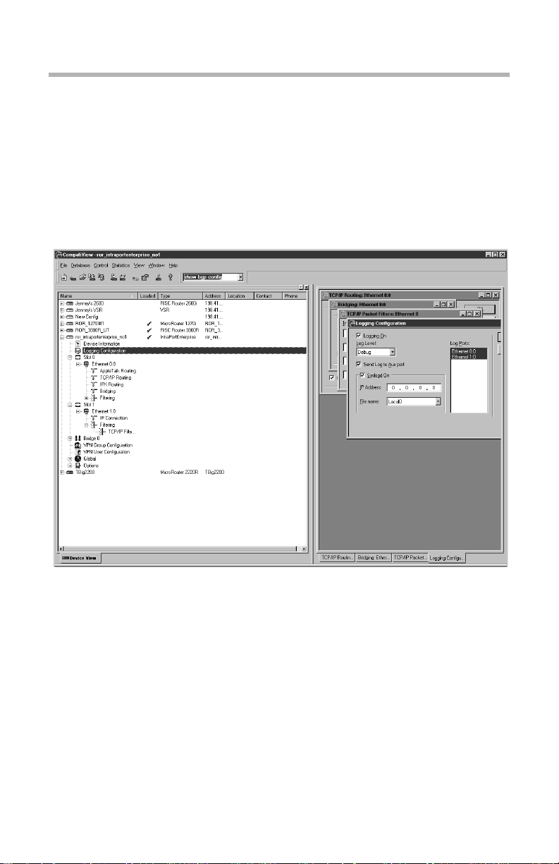
The Device View and the Main Window
The Device View The Main Window
The Device View displays a lis t of configurat ions. These conf igurations may
be generic configuration files which are not associated with a particular
device, or they may be a specific device’s configuration file. The File menu
allows you to add both types of configurations to the Device View.
Included in the window are the configuration’s name, type, network address,
and a checkmark if it has been loaded. Clicking on the + symbol next to a
device loads the device’s configuration into CompatiView’s memory and
brings up a list of the device’s configuration section icons, such as device
information, interfaces, global device settings, and options. Some of these
configuration section icons contain a further list of protocol icons.
Page 11

Chapter 1 - Installation and Overview 5
If the device is a multislot product such as a VSR or IntraPort Enterprise, both
the slot number and the interface number are shown, separated by a colon
(e.g., Ethernet 0:0 indicates Slot 0, Ethernet 0, while Ethernet 1:0 indicates
Slot 1, Ethernet 0).
Administrative information will also be included if it has been set u sin g the
Item Properties option under the Database Menu.
The list of configuration items associated with each device is an edit area. To
view or edit the configuration information for a specific interface and
protocol, click on the protocol icon. A configuration dialog box will be
opened in the Main Window.
The information in these configuration dialog boxes is used by a device’s
operating software to determine how it will interface with wide area communications devices, communicate on IPX subnets, filter network packets, etc.
If you determine that a device needs to use new or different configuration
information, you must change the configuration file which is stored in its
Flash ROM. (See the File Menu section for more information on downloading a set of configuration parameters to a device.)
If you have made changes to a configuration and then quit CompatiView
without downloading those changes, they will be lost.
If the parameters in an edit area ar e different from the configuration wh ich is
currently in the device (because of changes you have made in the edit area),
the protocol, interface and device labels in the Device View will be red.
v Note: Compatible Systems devices are designed to require less configura-
tion than other devices. Whenever possible, auto-configuration is used to
preset parameters with working values.
Right-Clicking in the Device View
Right-clicking when the mouse is on any item within the Device View will
bring up a menu which allows you to add or delete subinterfaces and VPN
ports, restart or delete the selected device, or set administrative properties,
including how the device will handle Save commands (see the Save/Restart
Tab under the Database Menu for more information). The other options are
also available as menu items and are documented in detail under the appropriate menu section.
Page 12

6 Chapter 1 - Installation and Overview
The File Menu
The File menu provides options which allow you to create and manage
configurations in CompatiView’s Device View.
New Config
This option loads default parameters for a particular type of device in the
Device View. You will first be asked to select a device type from a list. This
option may be useful to preconfigure a device or to use as a base configuration for multiple devices.
You can edit and view the parameter information by double-clicking on the
protocol icons under each configuration section icon. This window will
immediately reflect any values you change in the edit area.
> Open - Device
This option provides a way to load a device’s configuration into CompatiView’s Device View.
The exact method of adding a device depends on the transport protocol you
are using with CompatiView.
• If you are using the IPX transport stack, this menu item will open a list
of all the Compatible Systems devices on your networ k. Items wh ich are
not already entered in CompatiView’s Device View are marked with an
* in front of the device name.
• If you are using the IP transport stack, this menu item will open a
window in which you can enter the IP address or domain name of a
device.
Open - Config File
This option loads a previously saved configuration file from disk. This will
open a browser to allow you to select a configuration file.
> Save to - Device
This option allows you to download the changes you have made to a configuration from CompatiView to a device’s Flash ROM. Enter the IP address or
a DNS (Domain Name Service) Name for the device to download a configuration to.
Page 13
Chapter 1 - Installation and Overview 7
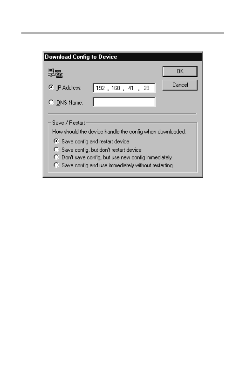
Download Config to Device Dialog Box
Save / Restart Options
The settings in this dialog box are specific for this device. For global
Save/Restart settings use the Database menu, select options, and choose the
Save/Restart tab. To change the Save/Restart mode for a particular device,
modify the “Device Properties” for that device.
• Save config and restart device. This parameter will save an edited
configuration to the device’s Flash ROM and restart the device to apply
the changes. This is the equivalent of the command line’s save
command.
• Save config, but don’t restart device. This parameter will save an
edited configuration without restarting the device. The changes will not
be applied until the device is restarted. This is the equivalent of the
command line’s write command.
• Don’t save config, but use new config immediately. This parameter
will apply an edited (but not saved) configuration to the device’s current
operations. If a restart occurs, changes will be lost. This is the equivalent
of the command line’s apply edited command.
• Save config and use immediately without restarting. This parameter
will save an edited configuration and immediately apply it to the device’s
Page 14

8 Chapter 1 - Installation and Overview
current operations without restarting the device. This is the equivalent of
issuing the apply command and then the write command in the
command line.
While the download is taking place, arrows will move in a circular motion
around the device icon in the Device View. To display the amoun t of time left
for the download, click on the + sign next to the device icon.
M Caution: Turning off a de vice in the mi ddle of a download m ay cause it to
lose its operating software. Please wait at least 5 minutes before deciding
that a download has failed to be stored in Flash ROM.
Save To - File
This option saves a configuration as a text file. Use this option to back up the
configurations you have downloaded to the devices on your network. When
you select this item, you will be asked to enter a file name. The edit area
which is exported will correspond to the current configuration.
v Note: Configuration text files are useful to Compatible Systems technical
support when diagnosing network problems. It is generally a good idea to
keep a full set of backup copies of your device configurations in case one of
your devices develops a hardware fault and must be r eplaced. It is not recommended that a text file be used to edit the configuration, since there is no
syntax checker and even small mistakes can create configuration errors.
If any changes are made to a configuration text file while CompatiView has
the configuration loaded, CompatiView will ask whether you wish to reload
the text file or keep CompatiView’s version. If you keep CompatiView’s
version, any externally made changes will be lost.
Subinterface
This option allows you to add or delete an IP subinterface to one of the
device’s current interfaces. Add opens a dialog box which allows you to
specify a port and the subinterface number to create. Delete opens a confirmation prompt to delete the subinterface. You must have a subinterface
selected to enable the Delete option.
VPN Port
This option allows you to add or delete VPN ports for the device. Add opens
a dialog box which allows you to specify the VPN port number to create.
Delete opens a conf irmation prom pt to delete the port . You must have a VPN
port selected to enable the Delete option.
Firewall Path
This option allows you to add or delete firewall paths for an IntraGuard Firewall. Add opens a dialog box which allows you to name the firewall path.
Page 15

Chapter 1 - Installation and Overview 9
Delete opens a confirmation pro mpt to del ete the path. You must have a firewall path selected to enable the Delete option.
View
This menu item brings up the Local Config View tab in the Output Window,
which displays the configuration text file for the current device.
This menu item prints the configuration text file for the current device.
Recent File
This menu item holds a list of files that have recently been saved.
> Exit
Exiting takes you out of CompatiView. If you made changes to the information in one or more edit areas (which will now appear in red) and have not
saved or downloaded them, you will be given an opportunity to do so.
The Database Menu
New Device Database
This option allows you to create con figuration database fi les. If no other dat abase files have been created, CompatiView automatically saves a database
file, “MASTER.INI,” every time you close. When you use this option, an
empty configuration database will be created to which you may add new
devices and configurations.
Open Device Database
This option allows you to open existing configuration database files. When
you use this option, a list of files will be opened. Select a file from the list, or
browse through the files to find the one you want.
Delete Device
Use this menu option to delete a configuration from CompatiView’s Device
View.
First, mark the configuration in the list you wish to delete by clicking on it.
When you select the Delete menu option, you will be asked whether you wish
to remove the configuration from the Device View.
Device Properties
Use this menu option to add administrative information for a particular
device. You can enter a device’s physical location, a contact name for the
device, and a phone number for the contact. This information is maintained
in CompatiView and is not downloaded into the device.
Page 16
10 Chapter 1 - Installation and Overview
Options
This menu item brings up a dialog box which lets y ou set a varie ty of option s
having to do with CompatiView’s operation.
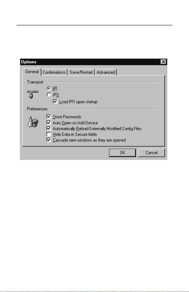
Database Options Dialog Box
General Tab
• IPX Transport - IP Transport. This set of radio buttons determines
whether CompatiView for Windows will use IPX or IP as a transport.
• Load IPX upon s tartup. CompatiView runs IPX behind the scenes to
generate IPX tables. I f you do not have IPX on your system, you may
want to leave this box unchecked so that CompatiView will not load IPX
upon startup.
• Store Passwords. This checkbox controls whether CompatiView saves
device passwords in its Device View. If you store passwords, you will
not need to enter them each time you log into a device.
• Auto Open on Add Device. This checkbox controls whether a device
configuration will be opened when it is added to the Device View.
• Automatically Reload Externally Modified Config Files. If this box is
checked, all changes made to the configuration files will automatically
Page 17

Chapter 1 - Installation and Overview 11
be loaded to the file on disk. If left unchecked, you will be prompted each
time the config files are changed and not loaded to disk.
• Hide Data in Secure fields. This checkbox will not show passwords in
display dialogs or edit boxes, or the text configuration of the current
device in Local Config View at the bottom of the screen. If this box is n ot
checked, passwords will be displayed in the clear.
• Cascade new windows as they are opened. This checkbox specifies
how the dialog boxes in the Main Window are displayed.
Confirmations Tab
• Confirm before deleting devices from the database. This checkbox
controls whether a confirmation prompt will appear before a device is
deleted from the Device View.
• Confirm before deleting subinterfaces. This checkbox controls
whether a confirmation prompt will appear before an IP subinterface is
deleted.
• Confirm before deleting VPN Ports. This checkbox controls whether a
confirmation prompt will appear before a VPN port is deleted.
• Confirm before deleting Firewall Paths. This checkbox controls
whether a confirmation prompt will appear before a firewall path is
deleted.
• Confirm configuration download. This checkbox controls whether a
confirmation prompt will appear before a configuration is downloaded to
a device.
• Confirm before restarting devices. This checkbox controls whether a
confirmation prompt will appear before a device is restarted.
• Confirm before resetting device statistics. This checkbox controls
whether a confirmation prompt will appear before resetting device statistics.
Save/Restart Tab v Note: These selections are global and only sets the “default” for a device
when it is added to the database. They do not change the mode for a device.
To change the Save/Restart mode f or a particular device, modify the “Device
Properties” for that device.
• Save config and restart device. This parameter will save an edited
configuration to the device’s Flash ROM and restart the device to apply
the changes. This is the equivalent of the command line’s save
command.
Page 18

12 Chapter 1 - Installation and Overview
• Save config, but don’t restart device. This parameter will save an
edited configuration without restarting the device. The changes will not
be applied until the device is restarted. This is the equivalent of the
command line’s write command.
• Don’t save config, but use new config immediately. This parameter
will apply an edited (but not saved) configuration to the device’s current
operations. If a restart occurs, changes will be lost. This is the equivalent
of the command line’s apply edited command.
• Save config and use immediately without restarting. This parameter
will save an edited configuration and immediately apply it to the device’s
current operations without restarting the device. This is the equivalent of
issuing the apply command and then the write command in the
command line.
v Note: Some of these options are not yet available for all Compatible
Systems products. To find out whether your device supports them, you must
right-click on any configuration item for that device in the Device View and
select Properties from the popup menu, then click on the Save/Restart tab.
Advanced Tab
• Packet Retry Interval. This parameter determines how long Compati-
View will wait for a response from a device before resending a packet.
The default value is 10 seconds.
• Maximum Connection Timeout. This parameter determines how long
CompatiView will continue retryi ng before giving up . The default val ue
is 40 seconds.
• SAP Update Interval. This parameter determines how frequently
CompatiView will retrieve SAP packets. When IPX is in use, lowering
this number may make devices appear more quickly when adding new
devices to the Device View. The default value is 20 seconds.
v Note: The default value of 40 seconds for the Maximum Connection
Timeout is long enough to bring up a modem-based dial-on-demand link.
The Control Menu
The Control menu is primarily concerned with operations on physical
devices.
Compatible Systems product s use F lash ROM technol ogy to stor e their op erating software and configuration parameters. Flash Rooms can be rewritten
tens of thousands of times and will maintain the information which has been
written in them regardless of whether they are powered on or not.
Page 19

Chapter 1 - Installation and Overview 13
The Control menu lets you update the software contained in the Flash ROM
of a device.
Download Software
When new features are added to the operating software for a particular type
of device, you may wish to update a device with the new version.
When you are using IPX tran sport protocols and select this option, a wi ndow
listing all eligible devices will appear. You will first be asked to select one or
more devices (which must all be of the same type). To s elect multiple devices,
hold down the Control key on your keyboard while clicking on devices.
When you are using IP transport protocols and select this option, you will be
asked to enter an IP address (the IP address of the current device will be
provided as a hint when the window opens).
Once you select one or more devices, CompatiView will log in to the first
device in the list (requesting a password from you if it isn’t stored in C ompatiView), and then will ask you to select a download file from disk. This file
will be downloaded into Flash ROM in the device(s).
Although the old software stored in Flash ROM will be overwritten, the
device will maintain any configuration information (addresses, device name,
password, etc.) you had previously loaded.
v Note: Whenever the Flash ROM in a device is downloaded, whether with
new software or with a new configuration, the device will automatically be
restarted. The download/restart process will take from 1 to 2 minutes,
depending on the amount of memory in the device.
TFTP Download
This menu option allows you to use the Trivial File Transfer Protocol (TFTP)
to download software to a device. This feature is generally only useful if you
have erased the operating software in a device’s Flash ROM and are
attempting to reload it.
When you select the option, you will be asked for an IP address. CompatiView will then provide a file dialog to allow you to choose the dow nload file.
v Note: T FTP can also be used to download operating software into a device
which is running standard software from Flash ROM.
Restart Device
Use this menu option to restart a device in CompatiView’s Device View.
Mark the device in the list you wish to restart by clicking on it. The device
you select will be restarted after you select this menu item.
Page 20

14 Chapter 1 - Installation and Overview
The Output Window
The CompatiView Output Window
There is an Output Window at the bottom of the Device View which lets you
quickly check the current status of the selected configuration parameter or
review the device configuration. The tabs show different types of parameter
values. In some cases, these parame ters may be differe nt than tho se stored in
the device’s Flash ROM due to auto-configuration.
The Output Window is broken up into three tabbed sections.
• The Local Config View tab displays the complete device configuration
and will reflect any changes you have made in the edit area for a d evice.
• The Device Information tab displays the hardware configuration of the
device.
• The Command Line Output tab is where output from the Stat istics
menu options will appear. This tab also displays information currently in
effect on the device.
The Statistics Menu
This menu allows you to display protocol routing tables and other information
for a device. The output from these options is displayed in the Command Line
Output tab in the Output Window. The specific menu options available
depend on the current device type.
The first set of menu items displays the same information that is available
when using certain commands within the command line interface. Refer to
the section in the Text-Based Configuration and Command Line Reference
Guide as indicated for a detailed description of the output from these menu
items.
v Note: If you are experienced with internetworking devices, the information
in these windows will be familiar to you. If you are not, this information can
Page 21

Chapter 1 - Installation and Overview 15
be used by Compatible Systems technical support to determine the cause of
many problems.
Ethernet
This menu item displays ethernet port statistics and is the equivalent of the
command line’s show ethernet statistics command. (See the
ethernet(show) section.)
WAN State
This menu item displays WAN port status and connection statistics and is the
equivalent of the command line’s show wan state command. (See the
wan(show) section.)
Serial Statistics
This menu item displays packet and physical layer statistics for the WAN
ports and is the equivalent of the command line’s s how wan serial statistics
command. (See the wan(show) section.)
RADIUS
This menu item displays packet statistics for the RADIUS client and is the
equivalent of the comma nd li ne’s show radius st atisti cs command. (See the
radius(show) section.)
PPP Statistics
This menu item displays packet statistics for WAN interfaces set for PPP and
is the equivalent of the command line’s show ppp statistics co mmand . (See
the ppp(show) section.)
Frame Relay Statistics
This menu item displays packet statistics for WAN interfaces set for Frame
Relay and is the equivalent of the command line’s show frelay statistics
command. (See the frelay(show) section.)
Frame Relay State
This menu item displays the status of the PVCs (Permanent Virtual Circuits)
on WAN interfaces set for Frame Relay and is the equivalent of the comman d
line’s show frelay pvc command. (See the frelay(show) section.)
ARP Cache
This menu item displays the ARP cache, which is the mapping b etween high
level protocol addresses and physi cal addresses . Thi s comm and is the equi valent of the command line’s show arp command. (See the arp(show)
section.)
Page 22

16 Chapter 1 - Installation and Overview
IP Route Table
This menu item displays the IP route table and is the equivalent of the
command line’s show ip routing command. (See the ip(show) section.)
IP Routing
This menu item displays IP statistics and is the equivalent of the command
line’s show ip statistics command. (See the ip(show) sectio n.)
IPX Route Table
This menu item displays the IPX route table, and is the equivalent of the
command line’s show ipx routing command. (See the ipx(show) section.)
IPX SAP Table
This menu item displays the IPX server table, and is the equivalent of the
command line’s show ipx sap command. (See the ipx(show) section.)
AppleTalk Route Table
This menu item displays the AppleTalk route table and is the equivalent of
the command line’s show appletalk routing command. (See the apple-
talk(show) section.)
AppleTalk Routing
This menu item displays AppleTalk statistics and is the equivalent of the
command line’s show appletalk statistics command. (See the apple-
talk(show) section.)
OSPF Configuration
This menu item displays user-co nfigured values that are curren tly being used
by the OSPF protocol and is the equivalent of the command line’s show ospf
config command. (See the ospf(show) section).
OSPF Packet Statistics
This menu item displays how many of each of the five types of OSPF packets
(Hello, Database Description, Link State Request, Link State Update, and
Link State Acknowledgement) have been received and sent. This is the equivalent of the command line’s show ospf st ats comm and. (See the ospf(show)
section).
OSPF Interface Database
This menu item displays the OSPF interface database and is the equivalent of
the command line’s show ospf if command. (See the ospf(show) section).
Page 23

Chapter 1 - Installation and Overview 17
OSPF Neighbors
This menu item displays an abbreviated list of current neighbors an their state.
This is equivalent to the command line’s show ospf nbr command. (See the
ospf(show) section)
Buffer
This menu item displays detailed information on the current status of the
device’s memory allocation and is the equivalent of the command line’s show
os memory command. (See the os(show) section.)
Show Restart Info
This menu item displays detailed information about the status of the device
when the last restart event occurred, and is the equivalent of the command
line’s show os resevent command. (See the os(show) section.)
Device Log
This menu item displays the log buffer, and is the equivalent of the command
line’s show system log buffer command. (See the system(show) section.)
Command Line Interface
This menu item allows you to enter other show commands in the Command
Line entry box, as described below.
Reset Statistics
This menu item sends a command to the current device which causes it to
reset all of its statistic counters.
The Command Line Edit Box
The Command Line Edit Box
This box is both a pull-down list and an edit box which allows you to enter
command line show commands. Any Statistics menu item you use will be
added to this pull-down menu . To enter other show commands which are not
included in the Statistics menu, choose the Statistics menu’s Command Line
Interface option to enter the command in the edit box. Press the Return key to
send the command to the device.
v Note: Other types of commands (e.g., reset, add, etc.) are not fully
supported by CompatiView. Only show commands should be used.
Page 24

18 Chapter 1 - Installation and Overview
Moving and Customizing the Windows
Right-clicking in the area between windows brings up a popup menu which
controls the placement of the windows.
• Allow Docking. This menu option, when checked, allows the window to
be docked in a firm place within the main window.
• Hide. This menu option will hide the selected window. Use the Window
menu to view a hidden window again.
Clicking and dragging the double bars at the top or side of a window allows
you to move the window around on the screen, according to the options
described above. Pressing the Control key as you click and drag will disable
docking, and the window can be placed anywhere on the screen, including
outside the Main window.
The View menu
Use this menu option to view your display in full screen or in workbook
mode. You can also change the size of the window or move the window
around the screen by clicking and dragging the double bars at the top of the
window.
Customize
To customize the display windows, select Customize in the View menu. This
dialog box gi ves options for customizing the to olbars and command icon s.
Page 25
Chapter 1 - Installation and Overview 19
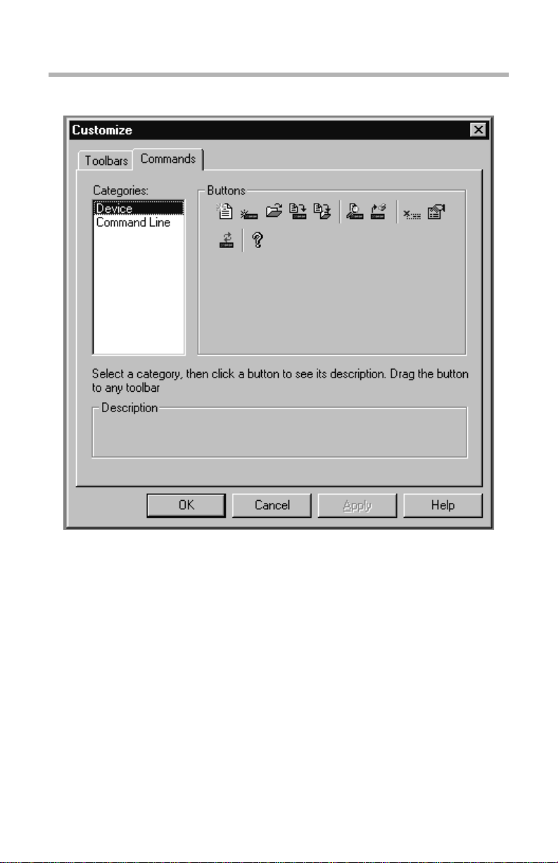
Customize Window View Dialog Box
Toolbars
This tab allows you to choose the toolbars that you want in your display
window.
Commands
This tab allows you to create your own toolbar by placing device commands
or command line button s onto any toolbar.
The Window Menu
This menu allows you to toggle the d atabase workspace (device view) and the
output window. You can also choose how your windows will be displayed in
the workspace.
Page 26

Page 27
Chapter 2 - IP Routing & Bridging 21
Chapter 2 - IP Routing & Bridging
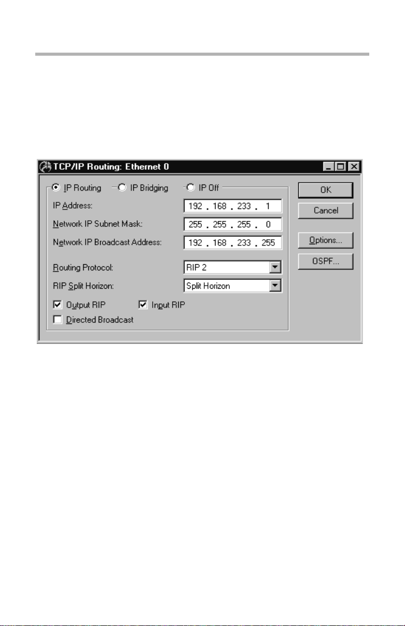
TCP/IP Routing: Ethernet Dialog Box
TCP/IP Routing: Ethernet Configuration Dialog Box
v Note: If you need more infor mation about t he IP protocol, see “IP 101” in
the Appendices to this manual.
To access this dialog box, select Ethernet/TCP/IP Routing from the Device
View.
> IP Routing/Bridging/Off
This set of radio buttons controls how IP packets are handled for this interface.
• If set to IP Routing, then IP packets received o n this interface are routed
to the correct interface on the router.
• If set to IP Bridging, then any IP packets received on this interface are
forwarded to the router’s internal bridge. This setting makes this Ethernet
interface a member of the “IP Bridge Group” for this router.
Page 28

22 Chapter 2 - IP Routing & Bridging
v Note: The IP Bridging radio button will be grayed out unless bridging has
been turned on globally for the device using the Main Bridgi ng Configuration
Dialog Box (under Global/Bridging) and locally on this interface using the
Bridging: Ethernet Dialog Box (under Ethernet/Bridging).
• If set to IP Off, then any IP packets received on this interface are
discarded.
> IP Address
Every network interface on an IP internetwork must have a unique
that identifies that interface to other devices on the internetwork. Part of this
address identifies the network segment the router interface is connected to,
and the remainder uniquely identifies the router interface itself.
This address should be entered as four decimal numbers separ ated by periods
-- for example 198.238.9.1
v Note: The single most common problem encountered in IP networking is
the use of a duplicate IP address. You must carefully track the network
numbers you have ass igned to vari ous devices i n order to avo id hard-to -diagnose problems.
IP address
> Network IP Subnet Mask
Most IP networks use “subnetting” in order to subdivide a large network into
smaller logical sub-networks. The subnet mask value is used to tell the router
what part of the IP address identifies the network segment (the “network”
portion), and what part identifies individual interfaces (the “host” portion).
There are three generally used “classes” of subnetted IP networks: A, B and
C. Each class uses a different amount of the IP address for the network and
host portions. These classes may also be further divided by correctly setting
the subnet mask.
If you do not enter a number in the Subnet Mask field, CompatiView will
derive a default value from the IP Address number you entered just above.
This default assumes you want a single subnet for all of the available host
addresses. You must manually set the field if you want to further divide the
address range.
To have CompatiView calculate a default mask, make sure that the Subnet
Mask field is empty, position the cursor in the IP Address field, then just tab
through the Subnet Mask field.
> Network IP Broadcast Address
The router will use this a ddress to s end any IP broadcast messages. The s ta ndard broadcast address is all 255’s (hexadecimal FFs) in the host portion of
Page 29

Chapter 2 - IP Routing & Bridging 23
the address. A few networks use all zeroes in this field. If you are unsure
which type your network uses, check with your network administrator.
To have CompatiView calculate a default broadcast address, make sure that
the Broadcast Address field is empty, position the curso r in the Subnet Mas k
field, then just tab through the Broadcast Address field.
> Routing Protocol
Routers exchange information about the most effective path for packet
transfer between various end poin ts. There are a number of different protocols
which have been defined to facilitate the exchange of this information.
Routing Information Protocol (RIP) 1 is the most widely used routing
protocol on IP netw ork s. A l l gat ew ays and routers that support RIP 1 periodically broadcast routing information packets. These RIP 1 packets contain
information concerning the networks that the router s and gateways can re ach
as well as the number of routers/gateways that a packet must travel through
to reach the receiving address.
RIP 2 is an enhancement of RIP 1 which allows IP subnet information to be
shared among routers, and provides for authentication of routing updates.
When this protocol is chosen, the router will use the multicast address
224.0.0.9 to send and/or receive RIP 2 packets for this network interface. As
with RIP 1, the router’s routing table will be periodically updated with information received in these packets.
RIP 2 is more useful in a variety of environments and allows the use of variable subnet masks on your network. It is also necessary for implementation
of “classless” addressing as accomplished with CIDR (Classless Inter
Domain Routing).
It is recommended that RIP 2 be used on any segment where all routers can
use the same IP routing protocol. If one or more routers on a segment must
use RIP 1, then all other routers on that segment should also be set to use RIP
1.
• If RIP 2 is selected with this pull-down menu, the router will send and/or
accept RIP 2 packets over this interface, and will then periodically update
its routing table with the information provided f rom thes e pack ets. On a
large network, an up-to-date routing table will enhance network performance since the router will always be aware of the optimal path to use
when sending packets.
• If RIP 1 is selected with this pull-down menu, the router will send and/or
accept RIP 1 packets, and will then periodically update its routing table
with the information provided from these packets.
Page 30

24 Chapter 2 - IP Routing & Bridging
• If None is selected with this pull-down menu, the router will not be able
to update its routing table and will always direct traffic for addresses it
does not have a route for (addresses not on one of th e networks connected
to its interfaces) to the “gateway/port” defined in its IP Static Route
Dialog Box. It will then be the responsibility of the default router to
direct the packets to the correct address. For information on setting the
default router see the discussion of the IP Static Route Dialog Box later
in this chapter.
v Note: Some routers, in particular those designed to create very large
corporate backbones, may use other routing protocols such as OSPF (Open
Shortest Path First). These routers can simultaneously use RIP 1 (and in
some cases RIP 2) to communicate with smaller routers, or each of the
smaller routers can be set to use one of these backbone routers as their
default router.
RIP Split Horizon
Normally, RIP uses a technique called sp lit horizon to avoid routing loop s and
allow smaller update packets. This technique specifies that when the router
sends a RIP update out a particular network interface, it should never include
routing information acquired over that same interface.
There is a variation of the split horizon technique called “poison reverse”
which specifies that all routes should be included in an update out a particular
interface, but that the metric should be set to infinity for those routes acquired
over that interface. One drawback is that routing update packet sizes will be
increased when using poison reverse.
• If Split Horizon is selected with this pull-down menu, the router will
apply the split horizon technique to routes being output over this interface.
• If No Split Horizon is selected with this pull-down menu, the router will
include all routes in an output packet, regardless of which interface they
were acquired over, and will use a normal metric.
• If Poison Reverse is selected with this pull-down menu, the router will
include all routes in an output packet, but will set the metric to infinity
for those routes which were acquired over this interface.
Output RIP - Input RIP
These flags control the behavior of RIP 1 and RIP 2 for this interface,
allowing the router to selectively send RIP, receive RIP, o r both. T he default
(assuming RIP 1 or RIP 2 is turned on in the Routing Protocol popup) is to
both send and receive.
Page 31

Chapter 2 - IP Routing & Bridging 25
Directed Broadcast
This checkbox sets whether the interface will forward
network-prefix-directed broadcasts. This is a security feature which can help
prevent your network from being used as an intermediary in certain kinds of
attacks which use ICMP echo traffic (pings) or UDP echo packets with fake
(i.e., “spoofed”) source addresses to inundate a victim with erron eous traffic.
Options
The options button brings up the Ethernet TCP/IP Options Dialog Box which
provides access to Proxy ARP, UDP Relays and other co nfiguration infor mation. This dialog box is discussed later in this chapter.
OSPF
This option button brings up the OSPF Dialog Box which allows the OSPF
routing protocol to be enabled. For more information on this dialog box and
other OSPF parameters, refer to Chapter 15 - OSPF.
Page 32

26 Chapter 2 - IP Routing & Bridging
TCP/IP Routing: WAN Configuration Dialog Box
TCP/IP Routing: WAN Configuration Dialog Box
v Note: If you need more infor mation about t he IP protocol, see “IP 101” in
the Appendices to this manual.
To access this dialog box, select WAN/TCP/IP Routing from the Device
View.
> IP Routing/Bridging/Off
This set of radio buttons controls how IP packets are handled for this interface.
• If set to IP Routing, then IP packets received o n this interface are routed
to the correct interface on the router.
• If set to IP Bridging, then any IP packets received on this interface are
forwarded to the router’s internal bridge. This setting makes this WAN
interface a member of the “IP Bridge Group” for this router.
Page 33

Chapter 2 - IP Routing & Bridging 27
v Note: The IP Bridging radio button will be grayed out unless bridging has
been turned on globally for the device using the Main Bridgi ng Configuration
Dialog Box (under Global/Bridging) and locally on this interface using the
Bridging: WAN Dialog Box (under WAN/Bridging).
• If set to IP Off, then any IP packets received on this interface are
discarded.
> Numbered Interface
This check box determines whether the Wide Area Network connected to this
interface will have an IP network number associated with it.
Many WAN connections are simple point-to-point links. These links do not
generally require a network number because there are only two devices on the
link. All traffic sent from one end is, by definition, destined for the other end.
You generally do not need a numbered WAN interface if you are using the
PPP transport protocol.
In contrast, Frame Relay networks may have a number of participating
routers connected through a single physical interface. Because of this, use of
the Frame Relay transport protocol requires
• If checked, then you must set an IP Address, Subnet Mask, and Broad-
cast Address (as described below) for this WAN interface. The default is
unchecked.
a numbered WAN interface.
v Note: If you are connecting the router to an Internet Service Provider
using PPP, you may be required to use a numbered interface. Check with
their tech support staff.
IP Address
Every network interface on an IP internetwork must have a unique
that identifies that interface to other devices on the internetwork. Part of this
address identifies the network segment the router interface is connected to,
and the remainder uniquely identifies the router interface itself.
This address should be entered as four decimal numbers separ ated by periods
-- for example, 198.238.9.5
v Note: The single most common problem encountered in IP networking is
the use of a duplicate IP address. You must carefully track the network
numbers you have ass igned to vari ous devices i n order to avo id hard-to -diagnose problems.
Network IP Subnet Mask
Most IP networks use “subnetting” in order to subdivide a large network into
smaller logical sub-networks. The subnet mask value is used to tell the router
IP address
Page 34

28 Chapter 2 - IP Routing & Bridging
what part of the IP address identifies the network segment (the “network”
portion), and what part identifies individual interfaces (the “host” portion).
There are three generally used “classes” of subnetted IP networks: A, B and
C. Each class uses a different amount of the IP address for the network and
host portions. These classes may also be further divided by correctly setting
the subnet mask.
If you do not enter a number in the Subnet Mask field, CompatiView will
derive a default value from the IP Address number you entered just above.
This default assumes you want a single subnet for all of the available host
addresses. You must manually set the field if you want to further divide the
address range.
To have CompatiView calculate a default mask, make sure that the Subnet
Mask field is empty, position the cursor in the IP Address field, then just tab
through the Subnet Mask field.
Network IP Broadcast Address
The router will use this a ddress to s end any IP broadcast messages. The s ta ndard broadcast address is all 255’s (hexadecimal FFs) in the host portion of
the address. A few networks use all zeroes in this field. If you are unsure
which type your network uses, check with your network administrator.
To have CompatiView calculate a default broadcast address, make sure that
the Broadcast Address field is empty, position the curso r in the Subnet Mas k
field, then just tab through the Broadcast Address field.
> Routing Protocol
Routers exchange information about the most effective path for packet
transfer between various end poin ts. There are a number of different protocols
which have been defined to facilitate the exchange of this information.
Routing Information Protocol (RIP) 1 is the most widely used routing
protocol on IP netw ork s. A l l gat ew ays and routers that support RIP 1 periodically broadcast routing information packets. These RIP 1 packets contain
information concerning the networks that the router s and gateways can re ach
as well as the number of routers/gateways that a packet must travel through
to reach the receiving address.
RIP 2 is an enhancement of RIP 1 which allows IP subnet information to be
shared among routers, and provides for authentication of routing updates.
When this protocol is chosen, the router will use the multicast address
224.0.0.9 to send and/or receive RIP 2 packets for this network interface. As
with RIP 1, the router’s routing table will be periodically updated with information received in these packets.
Page 35

Chapter 2 - IP Routing & Bridging 29
RIP 2 is more useful in a variety of environments and allows the use of variable subnet masks on your network. It is also necessary for implementation
of “classless” addressing as accomplished with CIDR (Classless Inter
Domain Routing).
It is recommended that RIP 2 be used on any segment where all routers can
use the same IP routing protocol. If one or more routers on a segment must
use RIP 1, then all other routers on that segment should also be set to use
RIP 1.
• If RIP 2 is selected with this pull-down menu, the router will send and/or
accept RIP 2 packets over this interface, and will then periodically update
its routing table with the information provided f rom thes e pack ets. On a
large network, an up-to-date routing table will enhance network performance since the router will always be aware of the optimal path to use
when sending packets.
• If RIP 1 is selected with this pull-down menu, the router will send and/or
accept RIP 1 packets, and will then periodically update its routing table
with the information provided from these packets.
• If None is selected with this pull-down menu, the router will not be able
to update its routing table and will always direct traffic for addresses it
does not have a route for (addresses not on one of th e networks connected
to its interfaces) to the “default router” defined in its IP Static Route
Dialog Box. It will then be the responsibility of the default router to
direct the packets to the correct address. For information on setting the
default router see the discussion of the IP Static Route Dialog Box later
in this chapter.
v Note: Some routers, in particular those designed to create very large
corporate backbones, may use other routing protocols such as OSPF (Open
Shortest Path First). These routers can simultaneously use RIP 1 (and in
some cases RIP 2) to communicate with smaller routers, or each of the
smaller routers can be set to use one of these backbone routers as their
default router.
> Update Method
WAN interfaces which are configured to provide “dial-on-demand” service
will bring a connection up (i.e. dial the other end) when there are network
packets which must be transferred over the link. Once a dial-on-demand
connection is up, network traffic passing across the link causes the inactivity
timer for the link to be reset, keeping the connection up.
The RIP protocol periodically sends out update information across a link.
These periodic update packets will cause a WAN interface set for
dial-on-demand operation to stay up indefinitely.
Page 36

30 Chapter 2 - IP Routing & Bridging
• If Triggered is selected with this pull-down menu, the router will modify
the standard RIP behavior for this interface to send RIP packets only
when there has been an update to its routing table information, or when
it has detected a change in the accessibility of the next hop router.
• If Periodic is selected with this pull-down menu, the router will use the
standard RIP protocol, which sends RIP packets over the link every 30
seconds.
RIP Split Horizon
Normally, RIP uses a technique called sp lit horizon to avoid routing loop s and
allow smaller update packets. This technique specifies that when the router
sends a RIP update out a particular network interface, it should never include
routing information acquired over that same interface.
There is a variation of the split horizon technique called “poison reverse”
which specifies that all routes should be included in an update out a particular
interface, but that the metric should be set to infinity for those routes acquired
over that interface. One drawback is that routing update packet sizes will be
increased when using poison reverse.
• If Split Horizon is selected with this pull-down menu, the router will
apply the split horizon technique to routes being output over this interface.
• If No Split Horizon is selected with this pull-down menu, the router will
include all routes in an output packet, regardless of which interface they
were acquired over, and will use a normal metric.
• If Poison Reverse is selected with this pull-down menu, the router will
include all routes in an output packet, but will set the metric to infinity
for those routes which were acquired over this interface.
Output RIP - Input RIP
These flags control the behavior of RIP 1 and RIP 2 for this interface,
allowing the router to selectively send RIP, receive RIP, o r both. T he default
(assuming RIP 1 or RIP 2 is turned on in the Routing Protocol popup) is to
both send and receive.
Directed Broadcast
This checkbox sets whether the interface will forward
network-prefix-directed broadcasts. This is a security feature which can help
prevent your network from being used as an intermediary in certain kinds of
attacks which use ICMP echo traffic (pings) or UDP echo packets with fake
(i.e., “spoofed”) source addresses to inundate a victim with erron eous traffic.
Page 37

Chapter 2 - IP Routing & Bridging 31
Options
The options button brin gs up t he WAN IP Option s Dialog Box w hich allows
you to set a Remote Node IP Address, Van Jacobson Header Compression,
and other configuration inform ation. This dialog box is discussed lat er in this
chapter.
OSPF
This option button brings up the OSPF Dialog Box which allows the OSPF
routing protocol to be enabled. For more information on this dialog box and
other OSPF parameters, refer to Chapter 15 - OSPF.
TCP/IP Routing: VPN Configuration Dialog Box
TCP/IP Routing: VPN Configuration Dialog Box
VPN (Virtual Private Network) ports must first be added to the edit area of a
device before they can be con figured. For more inform ation about adding and
deleting VPN ports, see Chapter 6 - VPN Ports and Tunnels.
Page 38

32 Chapter 2 - IP Routing & Bridging
Once you have created a VPN port, you may access the TCP/IP Routing:
VPN Configuration Dialog Bo x by clicking TCP/IP Routing un der t he VPN
port’s icon.
A VPN port is a virtual port which handles tunneled traffic. Tunnels are
virtual point-to-point connections through a public network such as the
Internet. All packets sent through a VPN tunnel are IP-en capsulated packets,
including AppleTalk, IPX and even IP packets. This encapsulation is added
or removed, depending on the direct ion, by “Tunnel Partner ” routers. Once a
packet reaches the remote Tunnel Partner, the TCP/IP encapsulation is
stripped off, leaving the ori ginal protoco l. The unencapsulat ed packet is then
handled according to the VPN port’s protocol configuration settings.
Networks connected via a tunnel will communicate as if they are on the same
network, even though they are separated by the Internet.
v Note: Remember that you must set up bo th ends of every tunnel. Therefore,
you must repeat this setup with the remote router.
> IP Routing/IP Bridging/IP Off
This set of radio buttons controls how IP packets are handled for this interface.
• If set to IP Routing, then IP packets received o n this interface are routed
to the correct interface on the device.
• If set to IP Bridging, then any IP packets received on this interface are
forwarded to the device’s internal bridge. This setting makes this VPN
port a member of the “IP Bridge Group” for this device.
v Note: The IP Bridging radio button will be grayed out unless bridging has
been turned on globally for the device using the Main Bridgi ng Configuration
Dialog Box (under Global/Bridging) and locally on this interface using the
Bridging: VPN Dialog Box (under VPN/Bridging).
• If set to IP Off, then any IP packets received on this interface are
discarded.
Numbered Interface
This check box determines whether the VPN port will have an IP network
number associated with it.
VPN tunnels are essent ially point-t o-point lin ks. These links do not gener ally
require a network number because all traffic sent from one end is, by definition, destined for the other end. However, you may w ish t o assi gn an addres s
for network tracking purposes.
Page 39

Chapter 2 - IP Routing & Bridging 33
• If checked, then you must set an IP Address, Subnet Mask, and Broad-
cast Address (as described below) for this VPN port. The default is
unchecked.
IP Address
If you wish to assign an IP address, it must be unique
identifies the network segment the router interface is connected to, and the
remainder uniquely identifies the router interface itself.
This address should be entered as four decimal numbers separ ated by periods
-- for example, 198.238.9.5
v Note: The single most common problem encountered in IP networking is
the use of a duplicate IP address. You must carefully track the network
numbers you have ass igned to vari ous devices i n order to avo id hard-to -diagnose problems.
Network IP Subnet Mask
Most IP networks use “subnetting” in order to subdivide a large network into
smaller logical sub-networks. The subnet mask value is used to tell the device
what part of the IP address identifies the network segment (the “network”
portion), and what part identifies individual interfaces (the “host” portion).
There are three generally used “classes” of subnetted IP networks: A, B and
C. Each class uses a different amount of the IP address for the network and
host portions. These classes may also be further divided by correctly setting
the subnet mask.
If you do not enter a number in the Subnet Mask field, CompatiView will
derive a default value from the IP Address number you entered just above.
This default assumes you want a single subnet for all of the available host
addresses. You must manually set the field if you want to further divide the
address range.
. Part of this address
To have CompatiView calculate a default mask, make sure that the Subnet
Mask field is empty, (re)position the cursor in the IP Address field, then just
tab through the Subnet Mask field.
Network IP Broadcast Address
The standard broadcast address is all 255’s (hexadecimal FFs) in the host
portion of the address. A few networks use all zeroes in this field. If you are
unsure which type your n etwork uses, check with y our network admi nistrator.
To have CompatiView calculate a default broadcast address, make sure that
the Broadcast Address field is empty, (re)position the cursor in the Subnet
Mask field, then just tab through the Broadcast Address field.
Page 40

34 Chapter 2 - IP Routing & Bridging
> Routing Protocol
Routers exchange information about the most effective path for packet
transfer between various end poin ts. There are a number of different protocols
which have been defined to facilitate the exchange of this information.
Routing Information Protocol (RIP) 1 is the most widely used routing
protocol on IP netw ork s. A l l gat ew ays and routers that support RIP 1 periodically broadcast routing information packets. These RIP 1 packets contain
information concerning the networks that the router s and gateways can re ach
as well as the number of routers/gateways that a packet must travel through
to reach the receiving address.
RIP 2 is an enhancement of RIP 1 which allows IP subnet information to be
shared among routers, and provides for authentication of routing updates.
When this protocol is chosen, the router will use the multicast address
224.0.0.9 to send and/or receive RIP 2 packets for this network interface. As
with RIP 1, the router’s routing table will be periodically updated with information received in these packets.
RIP 2 is more useful in a variety of environments and allows the use of variable subnet masks on your network. It is also necessary for implementation
of “classless” addressing as accomplished with CIDR (Classless Inter
Domain Routing).
It is recommended that RIP 2 be used on any segment where all routers can
use the same IP routing protocol. If one or more routers on a segment must
use RIP 1, then all other routers on that segment should also be set to use
RIP 1.
• If RIP 2 is selected with this pull-down menu, the router will send and/or
accept RIP 2 packets over this interface, and will then periodically update
its routing table with the information provided f rom thes e pack ets. On a
large network, an up-to-date routing table will enhance network performance since the router will always be aware of the optimal path to use
when sending packets.
• If RIP 1 is selected with this pull-down menu, the router will send and/or
accept RIP 1 packets, and will then periodically update its routing table
with the information provided from these packets.
• If None is selected with this pull-down menu, the router will not be able
to update its routing table and will always direct traffic for addresses it
does not have a route for (addresses not on one of th e networks connected
to its interfaces) to the “default router” defined in its IP Static Route
Dialog Box. It will then be the responsibility of the default router to
direct the packets to the correct address. For information on setting the
Page 41

Chapter 2 - IP Routing & Bridging 35
default router see the discussion of the IP Static Route Dialog Box later
in this chapter.
v Note: Some routers, in particular those designed to create very large
corporate backbones, may use other routing protocols such as OSPF (Open
Shortest Path First). These routers can simultaneously use RIP 1 (and in
some cases RIP 2) to communicate with smaller routers, or each of the
smaller routers can be set to use one of these backbone routers as their
default router.
> Update Method
VPN links which are configured to provide “dial-on-demand” service will
bring a connection up (i.e. dial the other end) when there are network packets
which must be transferred over the link. Once a dial-on-demand connection
is up, network traffic passing across the link causes the inactivity timer for the
link to be reset, keeping the connection up.
The RIP protocol periodically sends out update information across a link.
These periodic update packets will cause a VPN link set for dial-on-demand
operation to stay up indefinitely.
• If Triggered is selected with this pull-down menu, the router will modify
the standard RIP behavior for this link to send RIP packets only when
there has been an update to its routing table information, or when it has
detected a change in the accessibility of the next hop router.
• If Periodic is selected with this pull-down menu, the router will use the
standard RIP protocol, which sends RIP packets over the link every 30
seconds.
RIP Split Horizon
Normally, RIP uses a technique called sp lit horizon to avoid routing loop s and
allow smaller update packets. This technique specifies that when the device
sends a RIP update out a particular network interface, it should never include
routing information acquired over that same interface.
There is a variation of the split horizon technique called “poison reverse”
which specifies that all routes should be included in an update out a particular
interface, but that the metric should be set to infinity for those routes acquired
over that interface. One drawback is that routing update packet sizes will be
increased when using poison reverse.
• If Split Horizon is selected with this pull-down menu, the device will
apply the split horizon technique to routes being output over this interface.
Page 42

36 Chapter 2 - IP Routing & Bridging
• If No Split Horizon is selected with this pull-down menu, the device will
include all routes in an output packet, regardless of which interface they
were acquired over, and will use a normal metric.
• If Poison Reverse is selected with this pull-down menu, the device will
include all routes in an output packet, but will set the metric to infinity
for those routes which were acquired over this interface.
Output RIP - Input RIP
These flags control the behavior of RIP 1 and RIP 2 for this interface,
allowing the router to selectively send RIP, receive RIP, o r both. T he default
(assuming RIP 1 or RIP 2 is turned on in the Routing Protocol popup) is to
both send and receive.
Directed Broadcast
This checkbox sets whether the interface will forward
network-prefix-directed broadcasts. This is a security feature which can help
prevent your network from being used as an intermediary in certain kinds of
attacks which use ICMP echo traffic (pings) or UDP echo packets with fake
(i.e., “spoofed”) source addresses to inundate a victim with erron eous traffic.
OSPF
This option button brings up the OSPF Dialog Box which allows the OSPF
routing protocol to be enabled. For more information on this dialog box and
other OSPF parameters, refer to Chapter 15 - OSPF.
Page 43

Chapter 2 - IP Routing & Bridging 37
TCP/IP Routing: Bridge Configuration Dialog Box
IP Bridge Group
Port 0
Port 1
Port 2
Port 3
Multiport Router/Switch
IPX Bridge Group
Bridge Logical Diagram
v Note: If you need more information about bridging, see “Bridging 101”
in the Appendices to this manual.
Bridging operates on physical network addresses (such as Ethernet
addresses), rather than logical addresses (such as IP addresses). From the
standpoint of IP networking, interfaces which are set to bridge IP between
themselves appear as a single logical entity.
Thus, a device’s “IP B ridge Group ” is made up o f all of t he physical netw ork
interfaces in a device which have been set to bridge IP. This setting can be
found in the TCP/IP Routing Configuration Dialog Box for each individual
physical interface. For example, see the IP Routing On/Bridge/Off radio
buttons in the TCP/IP: Ethernet Routing Configuration Dialog Box.
Logically, the IP Bridge Group is treated by the device as an interface (Bridge
0). The settings in the TCP/IP Routing: Bridge 0 Conf iguration Dialog Box
(discussed next) determine the IP parameters for all of the physical network
interfaces which make up the IP Bridge Group. This is shown schematically
in the diagram above.
Page 44

38 Chapter 2 - IP Routing & Bridging
TCP/IP Routing: Bridge 0 Configuration Dialog Box
v Note: If you need more infor mation about t he IP protocol, see “IP 101” in
the Appendices to this manual.
To access this dialog box, select Bridge 0/TCP/IP Routing from the Device
View.
> IP Routing/Off
These radio buttons control whether IP packets received by a member interface of the IP Bridge Group are passed on for IP routing.
• If set to IP Routing, then IP packets received on a member interface of
the IP Bridge Group wh ich cannot s imply be bridged to another membe r
interface of the group are passed on for IP routing.
• If set to IP Off, then IP packets received on a member interface of the IP
Bridge Group which cannot be bridged to another member interface of
the group are dropped. This setting means that further IP configuration
information is not required for the IP Bridge Group.
> IP Address
Every network interface (including a logical interface, like the IP Bridge
Group) on an IP internetwork must have a unique
that interface to other devices on the internetwork. Part of this address identifies the network segment(s) the IP Bridge Group is connected to, and the
remainder uniquely identifies the IP Bridge Group itself.
IP address that identifies
Page 45

Chapter 2 - IP Routing & Bridging 39
This address should be entered as four decimal numbers separ ated by periods
-- for example 198.238.9.5
v Note: The single most common problem encountered in IP networking is
the use of a duplicate IP address. You must carefully track the network
numbers you have ass igned to vari ous devices i n order to avo id hard-to -diagnose problems.
> Network IP Subnet Mask
Most IP networks use “subnetting” in order to subdivide a large network into
smaller logical sub-networks. The subnet mask value is used to tell the device
what part of the IP address identifies the network segment (the “network”
portion), and what part identifies individual interfaces (the “host” portion).
There are three generally used “classes” of subnetted IP networks: A, B and
C. Each class uses a different amount of the IP address for the network and
host portions. These classes may also be further divided by correctly setting
the subnet mask.
If you do not enter a number in the Subnet Mask field, CompatiView will
derive a default value from the IP Address number you entered just above.
This default assumes you want a single subnet for all of the available host
addresses. You must manually set the field if you want to further divide the
address range.
To have CompatiView calculate a default mask, make sure that the Subnet
Mask field is empty, position the cursor in the IP Address field, then just tab
through the Subnet Mask field.
> Network IP Broadcast Address
The device will use this address to send any IP broadcast messages. The standard broadcast address is all 255’s (hexadecimal FFs) in the host portion of
the address. A few networks use all zeroes in this field. If you are unsure
which type your network uses, check with your network administrator.
To have CompatiView calculate a default broadcast address, make sure that
the Broadcast Address field is empty, position the curso r in the Subnet Mas k
field, then just tab through the Broadcast Address field.
> Routing Protocol
Routers pass information between themselves about the most effective path
for packet transfer between various end points. There are a number of
different protocols which have been d efined to facilitate the exchang e of this
information.
Routing Information Protocol (RIP) 1 is the most widely used routing
protocol on IP netw ork s. A l l gat ew ays and routers that support RIP 1 period-
Page 46

40 Chapter 2 - IP Routing & Bridging
ically broadcast routing information packets. These RIP 1 packets contain
information concerning the networks that the router s and gateways can re ach
as well as the number of routers/gateways that a packet must travel through
to reach the receiving address.
RIP 2 is an enhancement of RIP 1 which allows IP subnet information to be
shared among routers, and provides for authentication of routing updates.
When this protocol is chosen, the router will use the multicast address
224.0.0.9 to send and/or receive RIP 2 packets for this Bridge Group’s
member interfaces. As with RIP 1, the router’s routing table will be periodically updated with information received in these packets.
RIP 2 is more useful in a variety of environments and allows the use of variable subnet masks on your network. It is also necessary for implementation
of “classless” addressing as accomplished with CIDR (Classless Inter
Domain Routing).
It is recommended that RIP 2 be used on any logical network segment,
including multiple physical segments which are part of a logical IP Bridge
Group, where all routers can us e the same IP rout ing protocol . If one or mo re
routers on a segment must use RIP 1, then all other routers on that segment
should also be set to use RIP 1.
• If RIP 2 is selected with this pull-down menu, the router will send and/or
accept RIP 2 packets via this Bridge Group’s member interfaces, and will
then periodically update its routing table with the information provided
from these packets. On a large network, an up-to-date routing table will
enhance network performance since the router will always be aware of
the optimal path to use when sending packets.
• If RIP 1 is selected with this pull-down menu, the router will send and/or
accept RIP 1 packets, and will then periodically update its routing table
with the information provided from these packets.
• If None is selected with this pull-down menu, the router will not be able
to update its routing table and will always direct traffic for addresses it
does not have a route for (addresses not on one of th e networks connected
to its interfaces) to the “default router” defined in its IP Static Route
Dialog Box. It will then be the responsibility of the default router to
direct the packets to the correct address. For information on setting the
default router see the discussion of the IP Static Route Dialog Box later
in this chapter.
v Note: Some routers, in particular those designed to create very large
corporate backbones, may use other routing protocols such as OSPF (Open
Shortest Path First). These routers can simultaneously use RIP 1 (and in
some cases RIP 2) to communicate with smaller routers, or each of the
Page 47

Chapter 2 - IP Routing & Bridging 41
smaller routers can be set to use one of these backbone routers as their
default router.
RIP Split Horizon
Normally, RIP uses a technique called sp lit horizon to avoid routing loop s and
allow smaller update packets. This technique specifies that when the router
sends a RIP update out a particular network interface (including a Bridge
Group logical interface made up of multiple physical member interfaces), it
should never include routing information acquired over that same interface.
There is a variation of the split horizon technique called “poison reverse”
which specifies that all routes should be included in an update out a particular
interface, but that the metric should be set to infinity for those routes acquired
over that interface. One drawback is that routing update packet sizes will be
increased when using poison reverse.
• If Split Horizon is selected with this pull-down menu, the router will
apply the split horizon technique to routes being output over this Bridge
Group’s member interfaces.
• If No Split Horizon is selected with this pull-down menu, the router will
include all routes in output packets sent over this Bridge Group’s
member interfaces, regardless of which interface they were acquired
over, and will use a normal metric.
• If Poison Reverse is selected with this pull-down menu, the router will
include all routes in an output packet sent over this Bridge Group’s
member interfaces, but will set the metric to infinity for those routes
which were acquired over these interfaces.
Directed Broadcast
This checkbox sets whether the interface will forward
network-prefix-directed broadcasts. This is a security feature which can help
prevent your network from being used as an intermediary in certain kinds of
attacks which use ICMP echo traffic (pings) or UDP echo packets with fake
(i.e., “spoofed”) source addresses to inundate a victim with erron eous traffic.
Options
The options button brin gs up the Bridge-TCP/IP Rou ting Options Dialog Box
which provides access to Proxy ARP, UDP Relays and other configuration
information. This dialog box is discussed later in this chapter.
OSPF
This option button brings up the OSPF Dialog Box which allows the OSPF
routing protocol to be enabled. For more information on this dialog box and
other OSPF parameters, refer to Chapter 15 - OSPF.
Page 48

42 Chapter 2 - IP Routing & Bridging
IP Subinterface Dialog Box
Add IP Subinterface Dialog Box
IP Subinterface Configuration Dialog Box
Subinterfaces are added to the edit area of a device by right-clicking on any
configuration item for the device, then cho osing Sub interface/Add. To delete
a sub interface, right-click on the subinterface icon, then choose Subinterface/Delete. These functions are also available in the Device menu.
Once you have created a subinterface, you may access the IP Subinterface
Configuration Dialog Box by clickin g on TCP/IP under the s ubinterface icon.
IP subinterfaces allow the device to service more than one IP address range
on a single physical network segment.
Because a routed IP packet does not contain any information regarding which
networks it has passed across, the device must associate all IP packets
received from a physical segment with the primary interface connected to that
segment. As a result of this, the only IP parameters which can be set for
subinterfaces are the IP Address, IP Subnet Mask, and IP Broadcast Addr ess.
Page 49

Chapter 2 - IP Routing & Bridging 43
v Note: Subinterfaces are onl y allowed on WA N ports confi gured for Frame
Relay operation. They are not allowed on WAN ports configured for PPP.
Frame Relay Glacis must be statically mapp ed when subinter faces are in use,
because IARP can only resolve a physica l port, not a logical subinter face on
that port.
IP Connection Dialog Box
IP Connection Dialog Box
The IP Connection Dialog Box controls the IP settings for the IPSec-only port
on an IntraPort VPN Access Router with two or more Ethernet interfaces.
This port will only handle IPSec traffic (i.e., authenticated and/or encrypted
packets).
To access this dialog box, select Ethernet/TCP/IP Routing from the Device
View.
> IP On/IP Off
This set of radio buttons controls how IP packets are handled for this interface.
• If set to IP On, then IPSec packets received on this interface are routed
to the correct interface on the router.
• If set to IP Off, then any IP packets received on this interface are
discarded.
Page 50

44 Chapter 2 - IP Routing & Bridging
IP Address
This is the IP address of the IPSec port. It should be entered as four decimal
numbers separated by periods -- for example, 198.238.9.5
v Note: This IP address must be on the same IP network as the IPSec
Gateway, which is configured using the IPSec Gateway Dialog Box (under
Global/IPSec Gateway).
Network IP Subnet Mask
The subnet mask value is used to tell the router what part of the IP address
identifies the network segment (the “network” portion), and what part identifies individual interfaces (the “host” portion).
If you do not enter a number in the Subnet Mask field, CompatiView will
derive a default value from the IP Address number you entered just above.
This default assumes you want a single subnet for all of the available host
addresses. You must manually set the field if you want to further divide the
address range.
To have CompatiView calculate a default mask, make sure that the Subnet
Mask field is empty, position the cursor in the IP Address field, then just tab
through the Subnet Mask field.
Network IP Broadcast Address
The router will use this address to send any IP broadcast messages. To have
CompatiView calculate a default broadcast address, make sure that the
Broadcast Address field is empty, position the cursor in the Subnet Mask
field, then just tab through the Broadcast Address field.
Page 51

Chapter 2 - IP Routing & Bridging 45
IP Static Routing Dialog Box
Static IP Routing Configuration Dialog Box
Add Static Route Dialog Box
To open the Static IP Routing Configuration Dialog Box, select Global/IP
Static Routes. This d ialog box di splays st atic routes which have already been
entered, but is not used to add or modify the entries.
To add or modify IP static route entries, you must access the Add Static Route
Dialog Box by selecting the Add... or Modify... buttons in the Static IP
Routing Configurati on Dialog Bo x. The Add Stat ic Route Dialog Box allows
you to set a default IP router and to assign multiple static routes.
Page 52

46 Chapter 2 - IP Routing & Bridging
When you are finished adding entries, making changes, and marking deletions, click OK to store them in CompatiView’s edit area for the device, for
later downloading. If you click Cancel, CompatiView will discard any
changes and additions you made in this dialog box.
v Note: The “default router” is used as a “route of last resort” when your
device cannot determine where an IP packet should be sent. In very simple
routing setups, including connecting small networks to the Internet through
an Internet Service Provider, a default router entry may be the only routing
information required.
Static routes are used to provide information to the device about where IP
packets should be sent when the device itself has not been able to determine
a correct route for them using dynamic routing information acquired through
an IP routing protocol such as RIP.
In cases where the routing metrics (i.e. th e number o f ro uting ho ps to a d estination) are equal between a static route and a dynamic route, Compatible
Systems devices will use the dynamic route.
v Note: Static routes are more difficult to maintain and are generally not as
reliable as dynami cally determin ed routes. We r ecommend that you use static
routing only when the network do es not provide adequate routing inf ormation
through RIP.
> Destination
Enter an IP address here in decimal notation for which you wish to provide
static routing information. This can be a network address or an entire host
address (e.g. 198.238.9).
By convention, 0.0.0.0 is used here for a default router entry.
> Mask
Enter a mask value here to tell the device how much of the Destination
Address entry should be considered when deter mining the route for a packet.
If you simply tab into this field, CompatiView will calculate a standard mask
depending on the class of the Destination Address network. For instance,
255.255.255.0 tells the device to consider only the first three octets of a
packet’s address in determining whether it should be routed to the Gateway.
By convention, 0.0.0.0 is used here for a default router entry.
> Gateway
This section allows you to specify a gateway machine which is responsible
for packets being sent to the Destination Address.
• If IP Address is selected, enter the IP address of the gateway.
Page 53

Chapter 2 - IP Routing & Bridging 47
• If Port is selected, use the pull-down menu to select an interface on the
device you are configuring.
v Note: The name of a physi cal port can not be u sed when t hat port is confi g-
ured for Frame Relay operation. This is because the Frame Relay protocol
allows multiple IP addresses to be reached over a single physical port via
different PVCs (permanent virtual circuits).
> Metric
This is the number of “hops” that your device will assume exist between itself
and the Gateway. It is also the number of hops that will be reported to other
routers if you check the RIP box (as described below). When choosing how
to forward a packet, a router will always pick a route with fewer hops over
one with more. This value should be between 1 and 15.
v Note: If you enter a smaller metric number, this route will tend to be
preferred by your routers and other routers. If you enter a l arger number, this
route will tend to be overlooked in favor of other routes (if any exis t) with
lower metrics.
> Redistribute via
This pull-do wn menu indicat es whether a st atic route sh ould be redist ributed.
Only one protocol can be selected for redistributing each static route.
• If None is specified, the static route will not be redistributed. Only one
routing protocol can be selected for redistributing each static route.
• If RIP is specified, the static route entry will be redistributed into the RIP
routing protocol which means that other routers will be able to choose
this device as a way to forward packets to the destination address,
depending on the metric and what other routes are available.
Routing information received via RIP from other routers will be redistributed out other interfaces where RIP processing is enabled. When
routes are rebroadcast in this fashion, the metric for this route is
increased by 1, which increases the cost of the route.
• If OSPF1 or OSPF2 is specified, the static route entry will be redistrib-
uted into the OSPF routing proto col. The 1 or 2 refer to the two types of
external metrics which may be used in OSPF.
A type 1 cost is the sum of both the external cost and the internal cost
used to reach that router. The cost of a type 2 route is simply the external
cost, regardless of the interior (i.e., within OSPF) cost to reach that
router.
Page 54

48 Chapter 2 - IP Routing & Bridging
• If BGP is specified, the static route entry will be redistributed into the
BGP routing protocol.
Ethernet IP Options
Bridge IP Options
Ethernet or Bridge TCP/IP Options Dialog Box
To access this dialog box, select Ethern et/ or Bridge/TCP/IP Routing from th e
Device View, then click on the Options button.
This dialog box provides access to settings for IP Proxy ARP settings and the
UDP Forwarding Agents Dialog Box.
IP Proxy ARP
Proxy ARP (Address Resolution Protocol) is used to allow the network
portion of a group of IP addresses to be shared between several physical
network segments. An example would be sharing on e Clas s C add ress ran ge
between two physical Ethernets.
The ARP protocol itself provides a way for devices on an IP network to create
a mapping between physical (i.e. Ethernet) addresses and logical IP
addresses.
Proxy ARP makes use of this mapping feature by instructing a device to
answer ARP requests as a “proxy” for the IP addresses behind one of its interfaces. The device which sent the ARP request will then co rrectly assume that
it can reach the requested IP address by sending packets to the physical
address that was returned to it.
This technique effectively hides the fact that a network has been (further)
subnetted.
Page 55

Chapter 2 - IP Routing & Bridging 49
• If set to On, then any ARP request received on this interface whose IP
network portion matches the network portion of the IP address on
another interface of the device (as found by applying the Subnet Mask
for that interface to the IP address for that interface) will be answered by
the device with the physical address of this interface.
• If set to Off, then the device will only respond to ARP requests received
for its own IP interface address. This is the default setting.
v Note: Using Proxy ARP requires an in depth understanding of the work-
ings of the IP protocol, along with careful manipulation of the IP subnet
masks for the interfaces on a device. A more straigh tforward method of
achieving similar results is to use Bridging (if available in your device).
UDP Forwarding Agents (Relays)
The “Relays” button brings up a configuration dialog box that can be used to
turn on a relay agent in the d evice for UDP (User Datagram Protocol ) broadcast packets.
UDP Forwarding Agents Dialog Box
Normally, a device will not forward UDP broadcast packets. However, many
network applications use UDP broadcasts t o configure addresses, hostna mes,
and other information. If ho sts attempting to use these prot ocols are not on the
same network segment as the servers which provide the information, the hosts
will not receive a response unless a relay agent has been enabled in a device.
When a relay agent is enabled for an interface, the device is instructed to
forward specific protocols received on that interface to a Server IP Address.
The server does not need to reside on a network segment directly attached to
the device.
Page 56

50 Chapter 2 - IP Routing & Bridging
> Server IP Address
You may enter server IP addresses in this list. When the Server IP Address
edit box is selected, the Add, Delete, and Modif y buttons will be activated for
the list.
> UDP Ports/Protocols
This list allows you to enter the ports for which UDP relay will be performed.
The list will show the services for well known ports in parentheses. When the
UDP Port edit box is selected, the Add, Delete, and Modify buttons will be
activated for the list.
The pull-down menu on the UDP Port edit box provides a list of well known
services and automatically enters the UDP port number for a selected service
into the list.
WAN IP Options
WAN IP Options Dialog Box
To access this dialog box, select WAN/TCP/IP Routing from the Device
View, then click on the Options button.
This dialog box provides access to settings for Remo te Node IP Address, Van
Jacobson Header Compression, and IP Address Configure Request.
> Optional Remote End-Node Address
Besides defining a method for router-to-router communication, the PPP
protocol defines a method for indi vidual client machines to dial in to a router
interface. Once a client machine has connected to a router interface in this
fashion, the router provides prox y services which allow the client m achine to
participate as a node on one of the router’s local networks.
Page 57

Chapter 2 - IP Routing & Bridging 51
If remote node operation is desired, the W AN interface wo uld u sually be set
up as an unnumbered interface, and the Remote Node Address would then be
set to an unused IP address from the router’s Ethernet network(s).
Alternatively, if the interface is set to be numbered, an unused address from
the interface’s host range may be used.
As always, it is imperative in either case that this IP address be unique
The address should be entered as fo ur decimal numb ers separat ed by perio ds
-- for example 198.238.10.10
> Van Jacobson Header Compression
Named for the gentleman who developed it, VJHC (Van Jacobson Header
Compression) is a standard method of reducin g the amoun t of redundant IP
header information which is transferred over a wide area connection. VJHC
reduces the size of the IP header to as few as three bytes.
There is a trade-off between the amount of time it takes to compress the
header information, and the amount of time it would take to simply send it in
native form across the W AN link.
v Note: A general rule o f thumb for C ompatible Sys tems routers would be to
use VJHC on uncompress ed links at up to 56K rates, but to tur n it off at higher
speeds or if other means of compres sion (s uch as the V.4 2 compres sion bu ilt
into modems) are in use. A few simple file copy transfer tests over your particular WAN setup will yield a more exact answer.
Send IP Address Configure Request
A few third party routers implement the PPP specification in such a way that
they require a PPP Address Configure Request to be sent when IP communications are being negotiated. This checkbox tells the router to include such a
request with the IP address for this interface. Most routers do not require this
information, and this checkbox should generally be left unchecked (default
value).
.
Page 58

52 Chapter 2 - IP Routing & Bridging
TCP/IP Routing Options
TCP/IP Routing Options Dialog Box
This dialog box can be brought up selecting Options/TCP/IP Routing from
the Device View. These parameters are not associated with a particular interface and are global to the device.
RIP V2 Password
This password is used for authentication of RIP 2 packets received by the
device. It is also included in RIP 2 packets sent by the device.
IP Multiprotocol Precedence Dialog Box
IP Multiprotocol Precedence Dialog Box
This dialog box sets the precedence order the router will follow for including
routes in its routing table when multiple IP routing protocols are in use on the
network. To access this dialog box, select Global/IP Multiprotocol Precedence from the Device View.
Protocol Precedence
This pull-down menu sets the precedence order for including routes in the
device’s IP routing table. This parameter is only relevant if there is more than
one possible route to a destination. For example, if there are no OSPF or RIP
Page 59

Chapter 2 - IP Routing & Bridging 53
routes to a destination but there is a static route, that route will be installed
even if the precedence is Ospf Rip Static. Also, if there is a configured static
route to a destination for which there was a RIP or OSPF route with greater
precedence, that static route will be automatically re-installed if the
RIP/OSPF route goes away.
v Note: The BGP protocol will always be checked for first. Protocol Prece-
dence is used to set the precedence order for RIP, Static, and OSPF protocols.
v Note: An exception to the precedence rule is an OSPF external (i.e., type
ASE) route. OSPF external rou tes will be overwritten by a RIP or static route,
regardless of the precedence. This is because OSPF external routes originally come from another protocol, usually RIP or static. If the router is
running both RIP and OSPF, but another router on the network is redistributing RIP into OSPF, the RIP routes would be overwritten by OSPF external
routes without this exception. In order to get the RIP routes via OSPF
external routes, simply uncheck the Input RIP checkbox in the TCP/IP
Routing Dialog Box, and it will then install the routes as OSPF externals.
IP Route Redistribution
This section sets global configuration parameters which allow the redistribution of routes from one dyn amic IP routing p rotocol into an other. This allo ws
RIP, OSPF, and BGP protocols to co-exist and exchan ge routing i nformation.
Route redistribution is global to the device.
v Note: Redistribution of static routes can be done using the IP Multipro-
tocol Precedence Dialog Box.
Page 60

54 Chapter 2 - IP Routing & Bridging
IP Route Redistribution Dialog Box
To access this dialog box, select Global/IP Route Redistribution from the
device view.
OSPF Route Aggregation
This checkbox sets whether static and RIP routes will be consolidated along
class boundaries before they are advertised into OSPF. If the router has a split
subnet coming into the device from different interfaces, the box should be left
unchecked.
v Note: OSPF Route Aggregation i s o nl y us ed fo r imp or tin g s t ati c and RIP
routes into OSPF. Aggregation of BGP rout es is set in the BGP Ag gregatio n
dialog box. Refer to Chapter 16 - BGP for more information on configuration
of BGP.
RIP to OSPF
This checkbox sets whether the router will redistribute RIP routes into OSPF.
• Type 1 is the sum of both the external cost and the internal cost used to
reach that route.
Page 61

Chapter 2 - IP Routing & Bridging 55
• Type 2 is the external cost, regardless of the interior cost to reach that
route.
• The Metric parameter sets the external cost to be us ed. The value can be
a number between 1 and 32,767. For a type 1 route, the internal costs
along the routing path will be added to this cost to get the total cost.
Default into OSPF
This checkbox sets whether the router will redistribute default routes into
OSPF. If left unchecked, a RIP or BGP default route will not be advertised
into the OSPF domain even if non-d efault routes from t hat protocol are bei ng
redistributed.
• Type 1 is the sum of both the external cost and the internal cost used to
reach that route.
• Type 2 is the external cost, regardless of the interior cost to reach that
route.
• The Metric parameter sets the external cost to be us ed. The value can be
a number between 1 and 32,767. For a type 1 route, the internal costs
along the routing path will be added to this cost to get the total cost.
OSPF to RIP
This checkbox sets whether the router will redistribute OSPF routes in RIP.
If checked, RIP will pick up the OSPF routes along with any other routes it is
going to advertise.
BGP to OSPF
This checkbox sets whether the router will redistribute BGP routes into the
OSPF routing domain.
v Note: The full Internet BGP routing table cannot be redistrib uted into
OSPF. Only up to 1,000 BGP routes will be accepted.
BGP to RIP
This checkbox sets whether the router will redi stribu te BGP rout es into RIP.
If checked, RIP will pick up the BGP routes along with an y oth er ro utes it is
going to advertise.
RIP to BGP
This checkbox sets whether the router will redistribute RIP routes into the
BGP routing domain.
OSPF to BGP
This checkbox sets whether the router will redistribute OSPF routes into the
BGP routing domain.
Page 62

56 Chapter 2 - IP Routing & Bridging
v Note: BGP will provide its ow n hop count in its route advertisements.
Page 63

Chapter 3 - IPX Routing & Bridging 57
Chapter 3 - IPX Routing & Bridging
IPX Routing: Ethernet Configuration Dialog Box
IPX Routing: Ethernet Configuration Dialog Box
v Note: If you need more information about the IPX protocol, see “IPX 101”
in the Appendices to this manual.
To access this dialog box, select Ethernet/IPX Routing in the Device View.
IPX Ethernet Frame Types
Compatible Systems devices support all four defined IPX frame types, and
will perform routing between frame types as necessary. Whether each or all
of these frame types are used on an individual Ethernet interface is determined by the settings for each type.
Page 64

58 Chapter 3 - IPX Routing & Bridging
• Ethernet Type II is commonly used by TCP/IP and DECnet. The defau lt
seeding value is Non-Seed.
• Ethernet 802.3 (Raw) is the default frame type for earlier versions of
Novell Netware. The default seeding value is Auto-Seed.
• Ethernet 802.2 is a modified version of Ethernet_II and is the default
frame type for Novell Netware 4. The default seeding value is
Auto-Seed.
• Ethernet 802.2 SNAP is used by the AppleTalk protocol. The default
seeding value is Non-Seed.
> IPX Routing/Bridging/Off
This set of radio buttons controls how IPX packets are handled for this interface.
• If set to IPX Routing, then IPX packets received on this interface are
routed to the correct interface on the device.
• If set to IPX Bridging, then any IPX packets received on this interface
are forwarded to the device’s internal bridge. This setting makes this
Ethernet interface a member of the “IPX Bridge Group” for this device.
v Note: The IPX Bridging radio button will be grayed out unless bridging
has been turned on globally for the device using the Main Bridging Configuration Dialog Box (under Global/Bridging) and locally on this interface
using the E t hernet-Bridging Dial og Box (under Ethernet/Bridging).
• If it is set to IPX Off, then any IPX packets received on this interface are
discarded.
> Seed Status (per Frame Type)
One of the functions which routers perform in IPX internetworking is setting
the IPX network number for each network segment. A router which sets the
network number for a segment is said to have “seeded” the network.
• Seed means the device will listen for an IPX network number being set
by another router (i ncluding Novell s oftware rout ers residing o n servers)
on the segment connected to this interface and use this number if it exists.
If it doesn’t discover a number in use, the device will use the configured
IPX Network Number (discussed below) to set the network number for
the segment.
• Non-Seed means the device will listen for an IPX network number being
set by another router (including Novell software routers residing on
servers) on the segment connected to this interface and use this number
Page 65

Chapter 3 - IPX Routing & Bridging 59
if it exists. If it doesn’t discover a number in use, the device will wait
indefinitely until a number is set by another router on the segment.
• Auto-Seed means the device will listen for an IPX network number
being set by another router (including Novell software routers residing
on servers) on the segment connected to this interface and use this
number if it e xis ts. If it does n’t discover a num ber in use, the device will
auto-generate a valid number using its routing tables.
• Off means the device will neither listen for, nor send packets with this
frame type on this interface.
> Network Number (per Frame Type)
This is an eight-digit hexadecimal number that uniquely identifies the
network segment connected to this interface. Values range from 1 to
FFFFFFFE.
v Note: Accidental selection of an IPX network number which is alrea dy in
use on another net work segm ent ma y cause har d-to-di agnos e prob lems. You
should carefully track which IPX network numbers are in use, and where they
are used.
RIP Update Timer
This value dictates how often the device sends out IPX RIP (Routing Information Protocol) packets on the network segment attached to this interface.
The RIP packets sent out on this interface con tain information about networks
for which this device is responsible. RIP packets received tell the device
about other networks and routers. The default is 60 seconds.
SAP Update Timer
This value dictates how often the device sends out IPX SAP (Service Access
Protocol) packets on the network segment attached to this interface. The SAP
packets sent out on this interface contain information about s ervices (such as
servers, printers, etc.) for which this device is responsible. SAP packets
received tell this device about services available on other network segments.
The default is 60 seconds.
Block IPX Type 20 Output Packets
In order for some protocols, notably NetBIOS, to function in the NetWare
environment, routers must propagate a certain type of broadcast packet
throughout an IPX inter network. IPX packet t ype 20 is design ated to perform
broadcast propagation for these protoc ols .
When an IPX device receives a type 20 packet, it rebroadcasts it out all interfaces, except the one on which it was received. The IPX network number of
the originating interface is included in the rebroadcast packets.
Page 66

60 Chapter 3 - IPX Routing & Bridging
This checkbox allows you to control the rebroadcasting of IPX type 20
packets on this interface. This is useful for on-demand WAN links where the
link may be brought up as a result of propagating this type of packet.
• If checked, then type 20 packets will not be propagated on this interface.
The default is unchecked.
IPX Routing: WAN Configuration Dialog Box
IPX Routing: WAN Configuration Dialog Box
v Note: If you need more information about the IPX protocol, see “IPX 101”
in the Appendices to this manual.
To access this dialog box, select WAN/IPX Routing in the Device View.
> IPX Routing/Bridging/Off
This set of radio buttons controls how IPX packets are handled for this
interface.
Page 67

Chapter 3 - IPX Routing & Bridging 61
• If set to IPX Routing, then IPX packets received on this interface are
routed to the correct interface on the device.
• If set to IPX Bridging, then any IPX packets received on this interface
are forwarded to the device’s internal bridge. This setting makes this
interface a member of the “IPX Bridge Group” for this device.
v Note: The IPX Bridging radio button will be grayed out unless bridging
has been turned on globally for the device using the Main Bridging Configuration Dialog Box (under Global/Bridging) and locally on this interface
using the WAN-Bridging Dialog Box (under WAN/Bridging).
• If it is set to IPX Off, then any IPX packets received on this interface are
discarded.
> Numbered Interface
This checkbox determines whether the Wide Area Network connected to this
interface will have an IPX network number associated with it.
Many WAN connections are simple point-to-point links. These links do not
generally require a network number because there are only two devices on the
link. All traffic sent from one end is, by definition, destined for the other end.
You generally do not need a numbered WAN interface if you are using the
PPP transport protocol.
In contrast, Frame Relay networks may have a number of participating
devices connected through a single physical interface. Because of this, use of
the Frame Relay transport protocol requires
a numbered WAN interface.
• If checked, then you must set an IPX Network Number (as described
below) for this WAN interface. The default is unchecked.
Network Number
This is an eight-digit hexadecimal number that uniquely identifies the
network segment connected to this interface. Values range from 1 to
FFFFFFFE.
v Note: Accidental selection of an IPX network number which is alrea dy in
use on another net work segm ent ma y cause har d-to-di agnos e prob lems. You
should carefully track which IPX network numbers are in use, and where they
are used.
> Update Method
WAN interfaces which are configured to provide “dial-on-demand” service
will bring a connection up (i.e. dial the other end) when there are network
packets which must be transferred over the link. Once a dial-on-demand
Page 68

62 Chapter 3 - IPX Routing & Bridging
connection is up, network traffic passing across the link causes the inactivity
timer for the link to be reset, keeping the connection up.
The IPX RIP protocol perio dically sends out update information across a link.
These periodic update packets will cause a WAN interface set for
dial-on-demand operation to either stay up indefinitely, or to continuously
dial, connect, and then drop the connection.
• If Triggered is selected with this pull-down menu, the device will
modify the standard IPX RIP behavior for th is interface to send I PX RIP
packets only when there has been an update to its routing table information, or when it has detected a change in the accessibility of the next hop
router.
• If Periodic is selected with this pull-down menu, the device will use the
standard IPX RIP protocol, w hich sends RI P packets ov er the link base d
on the RIP Update Timer value set below.
RIP Update Timer
This value dictates how often the device sends out IPX RIP (Routing Information Protocol) packets on the WAN link attached to this interface. The RIP
packets sent out on this interface contain information about networks for
which this device is responsible. RIP packets received tell the device about
other networks and routers. The def ault is 60 seconds.
SAP Update Timer
This value dictates how often the device sends out IPX SAP (Service Access
Protocol) packets on the WAN link attached to this interface. The SAP
packets sent out on this interface contain information about s ervices (such as
servers, printers, etc.) for which this device is responsible. SAP packets
received tell this device about services available on other network segments.
The default is 60 seconds.
Optional Remote Node Network Number
Besides defining a method for router-to-router communication, the PPP
protocol defines a method for indi vidual client machines to dial in to a router
interface. Once a client machine has connected to a router interface in this
fashion, the router provides prox y services which allow the client m achine to
participate as a node on one of the router’s local networks.
If remote node operation is desired, the W AN interface wo uld u sually be set
up as an unnumbered interface, and the Remote Node Network Number
would then be set to an IPX network number from the router’s Ethernet
interface(s).
Alternatively, if the interface is set to be numbered, an unused IPX network
number may be used.
Page 69

Chapter 3 - IPX Routing & Bridging 63
Use Ethernet Port as End-Node Proxy
The router can be set to dynamically reserve an IPX address for this WAN
interface on an Ethernet segment. This proxy address will then be used if the
remote PPP IPX implementation requests address negotiation (generally used
by end-node clients).
Since the reserved address will be assigned to this interface, this checkbox
can only be checked on an interface set to be unnumbered.
• If checked, then an IPX address will be reserved for this WAN interface
on an Ethernet segment. The default is unchecked.
Block IPX Type 20 Output Packets
In order for some protocols, notably NetBIOS, to function in the NetWare
environment, routers must propagate a certain type of broadcast packet
throughout an IPX inter network. IPX packet t ype 20 is design ated to perform
broadcast propagation for these protoc ols .
When an IPX router receives a type 20 packet, it rebroadcasts it out all interfaces, except the one on which it was received. The IPX network number of
the originating interface is included in the rebroadcast packets.
This checkbox allows you to control the rebroadcasting of IPX type 20
packets on this interface. This is useful for on-demand WAN links where the
link may be brought up as a result of propagating this type of packet.
• If checked, then type 20 packets will not be propagated on this interface.
The default is unchecked.
v Note: Novell’s router specification recommends that type 20 packets not
be propagated acros s links with bandwidth s of less than 1 megab it per second
(such as asynchronous dial-up links and 56K leased lines).
Page 70

64 Chapter 3 - IPX Routing & Bridging
IPX Routing: VPN Configuration Dialog Box
IPX Routing: VPN Configuration Dialog Box
VPN (Virtual Private Network) ports must first be added to the edit area of a
device before they can be con figured. For more inform ation about adding and
deleting VPN ports, see Chapter 6 - VPN Ports and Tunnels.
Once you have created a VPN port, you may access the IPX Routing: VPN
Configuration Dialog B ox by cl ickin g on IP X Rout ing under the V PN port’s
icon.
A VPN port is a virtual port which handles tunneled traffic. Tunnels are
virtual point-to-point connections through a public network such as the
Internet. All packets sent through a VPN tunnel are IP-en capsulated packets,
including AppleTalk, IPX and even IP packets. This encapsulation is added
or removed, depending on the direction, by “Tunnel Partner” devices. Once a
packet reaches the remote Tunnel Partner, the TCP/IP encapsulation is
stripped off, leaving the ori ginal protoco l. The unencapsulat ed packet is then
handled according to the VPN port’s protocol configuration settings.
Networks connected via a tunnel will communicate as if they are on the same
network, even though they are separated by the Internet.
v Note: Remember that you mu st set up both ends of every tunnel. Ther efore,
you must repeat this setup with the remote device.
Page 71

Chapter 3 - IPX Routing & Bridging 65
To access this dialog box, select VPN/IPX Routing in the Device View.
> IPX Routing/Bridging/Off
This set of radio buttons controls how IPX packets are handled for this
interface.
• If set to IPX Routing, then IPX packets received on this interface are
routed to the correct interface on the device.
• If set to IPX Bridging, then any IPX packets received on this interface
are forwarded to the device’s internal bridge. This setting makes this
interface a member of the “IPX Bridge Group” for this device.
v Note: The IPX Bridging radio button will be grayed out unless bridging
has been turned on globally for the device using the Main Bridging Configuration Dialog Box (under Global/Bridging) and locally on this interface
using the VPN-Bridging Dialog Box (under VPN/Bridging).
• If it is set to IPX Off, then any IPX packets received on this interface are
discarded.
Numbered Interface
This checkbox determines whether the VPN port will have an IPX network
number associated with it.
VPN tunnels are essent ially point-t o-point lin ks. These links do not gener ally
require a network number because all traffic sent from one end is, by definition, destined for the other end. However, you may w ish t o assi gn an addres s
for network tracking purposes.
Network Number
This IPX Network Number is an eight-digit hexadecimal number that
uniquely identifies the network segment(s) connected to this interface. Values
range from 1 to FFFFFFFE.
v Note: Accidental selection of an IPX network number which is alrea dy in
use on another net work segm ent ma y cause har d-to-di agnos e prob lems. You
should carefully track which IPX network numbers are in use, and where they
are used.
> Update Method
VPN links which are configured to provide “dial-on-demand” service will
bring a connection up (i.e. dial the other end) when there are network packets
which must be transferred over the link. Once a dial-on-demand connection
is up, network traffic passing across the link causes the inactivity timer for the
link to be reset, keeping the connection up.
Page 72

66 Chapter 3 - IPX Routing & Bridging
The IPX RIP protocol perio dically sends out update information across a link.
These periodic update packets will cause a VPN link set for dial-on-demand
operation to either stay up indefinitely, or to continuously dial, connect, and
then drop the connection.
• If Triggered is selected with this pull-down menu, the device will
modify the standard IPX RIP behavior for this link to send IPX RIP
packets only when there has been an update to its routing table information, or when it has detected a change in the accessibility of the next hop
router.
• If Periodic is selected with this pull-down menu, the device will use the
standard IPX RIP protocol, w hich sends RI P packets ov er the link base d
on the RIP Update Timer value set below.
RIP Update Timer
This value dictates how often the device sends out IPX RIP (Routing Information Protocol) packets on the network s egmen ts attached to this interf ace.
The RIP packets sent out on this interface con tain information about networks
for which this device is responsible. RIP packets received tell the device
about other networks and routers. The default is 60 seconds.
SAP Update Timer
This value dictates how often the device sends out IPX SAP (Service Access
Protocol) packets on the network segments attached to this interface. The
SAP packets sent out on this interface contain information about services
(such as servers, printers, etc.) for which this device is responsible. SAP
packets received tell this device about services available on other network
segments. The default is 60 seconds.
Block IPX Type 20 Output Packets
In order for some protocols, notably NetBIOS, to function in the NetWare
environment, devices must propagate a certain type of broadcast packet
throughout an IPX inter network. IPX packet t ype 20 is design ated to perform
broadcast propagation for these protoc ols .
When an IPX device receives a type 20 packet, it rebroadcasts it out all interfaces, except the one on which it was received. The IPX network number of
the originating interface is included in the rebroadcast packets.
This checkbox allows you to control the rebroadcasting of IPX type 20
packets on this interface. This is useful for on-demand links where the link
may be brought up as a result of propagating this type of packet.
• If checked, then type 20 packets will not be propagated on this interface.
The default is unchecked.
Page 73

Chapter 3 - IPX Routing & Bridging 67
v Note: Novell’s router specification recommends that type 20 packets not
be propagated acros s links with bandwidth s of less than 1 megab it per second
(such as asynchronous dial-up links and 56K leased lines).
IPX Routing: Bridge Configuration Dialog Box
IP Bridge Group
Port 0
Port 1
Port 2
Port 3
IPX Bridge Group
Multiport Router/Switch
Bridge Logical Diagram
v Note: If you need more information about bridging, see “Bridging 101”
in the Appendices to this manual.
Bridging operates on physical network addresses (such as Ethernet
addresses), rather than logical addresses (such as IPX addresses). From the
standpoint of IPX networking, interfaces which are s et to bridge IPX between
themselves appear as a single logical entity.
Thus, a device’s “IPX Bridge Group” is made up of all of the physical
network interfaces in a device which have been s et to bridge IPX. This setting
can be found in the IPX Configuration Dialog Box for each individual physical interface. For example, see the IPX Routing/Bridging/Off radio buttons
in the IPX Routing: Ethernet Configuration Dialog Box.
Page 74

68 Chapter 3 - IPX Routing & Bridging
Logically, the IPX Bridge Group is treated by the device as an interface
(Bridge 0). The settings in the IPX Routing: Bridge 0 Configuration Dialog
Box (discussed below) determine the IPX parameters for all of the physical
network interfaces which make up the IPX Bridge Group. This is shown schematically in the diagram above.
IPX Routing: Bridge 0 Configuration Dialog Box
v Note: If you need more information about the IPX protocol, see “IPX 101”
in the Appendices to this manual.
To access this dialog box, select Bridge 0/IPX Routing in the Device View.
IPX Frame Types
Compatible Systems devices support all four defined IPX frame types, and
will perform routing between frame types as necessary. Whether each or all
of these frame types are used on an individual Bridge interface is determined
by the settings for each type.
• Ethernet Type II is commonly used by TCP/IP and DECnet. The defau lt
seeding value is Non-Seed.
Page 75

Chapter 3 - IPX Routing & Bridging 69
• Ethernet 802.3 (Raw) is the default frame type for earlier versions of
Novell Netware. The default seeding value is Auto-Seed.
• Ethernet 802.2 is a modified version of Ethernet_II and is the default
frame type for Novell Netware 4. The default seeding value is
Auto-Seed.
• Ethernet 802.2 SNAP is used by the AppleTalk protocol. The default
seeding value is Non-Seed.
> IPX Routing/Off
These radio buttons control whether IPX packets received by a member interface of the IPX Bridge Group are passed on for IPX routing.
• If set to Routing, then IPX packets received on a member interface of the
IPX Bridge Group which cannot simply be bridged to another member
interface of the group are passed on for IPX routing.
• If set to Off, then IPX packets received on a member interface of the IPX
Bridge Group which cannot be bridged to another member interface of
the group are dropped. This setting means that further IPX configuration
information is not required for the IPX Bridge Group.
> Seed Status (per Frame Type)
One of the functions which routers perform in IPX internetworking is setting
the IPX network number for each ne twork s egm ent. A de vice which sets the
network number for a segment is said to have “seeded” the network.
Remember that all segments connected to interfaces which are members of an
IPX Bridge Group will appear as the same logical segment.
• Seed means the device will listen for an IPX network number being set
by another device (including Novell software routers residing on servers)
on the segment(s) connected to this interface and use this number if it
exists. If it doesn’t discover a number in use, the device will use the
configured IPX Network Number (discussed below) to set the network
number for the segment(s)
• Non-Seed means the device will listen for an IPX network number being
set by another router (including Novell software routers residing on
servers) on the segment(s) connected to this interface and use this
number if it e xis ts. If it does n’t discover a num ber in use, the device will
wait indefinitely until a number is set by another router on the
segment(s).
• Auto-Seed means the device will listen for an IPX network number
being set by another router (including Novell software routers residing
on servers) on the segment(s) connected to this interface and use this
Page 76

70 Chapter 3 - IPX Routing & Bridging
number if it e xis ts. If it does n’t discover a num ber in use, the device will
auto-generate a valid number using its routing tables.
• Off means the device will neither listen for, nor send packets with this
frame type on this interface.
> Network Number (per Frame Type)
This is an eight-digit hexadecimal number that uniquely identifies the
network segment(s) connected to this interface. Values range from 1 to
FFFFFFFE.
v Note: Accidental selection of an IPX network number which is alrea dy in
use on another net work segm ent ma y cause har d-to-di agnos e prob lems. You
should carefully track which IPX network numbers are in use, and where they
are used.
RIP Update Timer
This value dictates how often the device sends out IPX \RIP (Routing Information Protocol) packets on the network segment(s) attached to this interface.
The RIP packets sent out on this interface con tain information about networks
for which this device is responsible. RIP packets received tell the device
about other networks and routers. The default is 60 seconds.
SAP Update Timer
This value dictates how often the device sends out IPX SAP (Service Access
Protocol) packets on the network segment(s) attached to this interface. The
SAP packets sent out on this interface contain information about services
(such as servers, printers, etc.) for which this device is responsible. SAP
packets received tell this device about services available on other network
segments. The default is 60 seconds.
Block IPX Type 20 Output Packets
In order for some protocols, notably NetBIOS, to function in the NetWare
environment, routers must propagate a certain type of broadcast packet
throughout an IPX inter network. IPX packet t ype 20 is design ated to perform
broadcast propagation for these protoc ols .
When an IPX device receives a type 20 packet, it rebroadcasts it out all interfaces, except the one on which it was received. The IPX network number of
the originating interface is included in the rebroadcast packets.
This checkbox allows you to control the rebroadcasting of IPX type 20
packets on this interface. This is useful for on-demand WAN links where the
link may be brought up as a result of propagating this type of packet.
• If checked, then type 20 packets will not be propagated on this interface.
The default is unchecked.
Page 77

Chapter 4 - AppleTalk Routing & Bridging 71
Chapter 4 - AppleTalk Routing & Bridging
AppleTalk Routing: Ethernet Configuration Dialog Box
AppleTalk Routing: Ethernet Configuration Dialog Box
v Note: If you need more information about the AppleTalk protocol, see
“AppleTalk 101” in the Appendices to this manual.
To access this dialog box, select Ethernet/AppleTalk Routing in the Device
View.
AppleTalk Phase 1 Configuration
AppleTalk Phase 1 is an earlier version of the AppleTalk protocol which is
still in use on some large legacy networks. Compatible Systems routers
support this protocol, and “transitional routing” between it and AppleTalk
Phase 2.
Page 78

72 Chapter 4 - AppleTalk Routing & Bridging
v Note: Although Compatible Systems rout ers support A ppleTalk Phase 1,
we recommend that all new AppleTalk installations use AppleTalk Phase 2,
which is much more capable.
v Note: In transitional routing insta llations, the same range of potential
AppleTalk network numbers is shared by both Phase 1 and Phase 2. Care
must be taken to avoid network number conflicts in these installations.
> Phase 1 Routing/Bridging/Off
This set of radio butt ons controls how Appl eTalk Phase 1 packets are handled
for this interface.
• If set to Phase 1 Routing, then AppleTalk Phase 1 packets received on
this interface are routed to the correct interface on the router.
• If set to Phase 1 Bridging, then any AppleTalk Phase 1 packets received
on this interface are forwarded to the router’s internal bridge. This setting
makes this Ethernet interface a member of the “AppleTalk Phase 1
Bridge Group” for this router.
v Note: The Phase 1 Bridging radio button will be grayed out unless
bridging has been turned on globally for the device using the Main Bridging
Configuration Dialog Box (under Global/Bridging) and locally on this interface using the Bridging: Ethernet Dialog Box (under Ethernet/Bridging).
• If it is set to Phase 1 Off, then any AppleTalk Phase 1 packets received
on this interface are discarded.
Phase 1 Seed Status
One of the functions whic h r out er s p e rfo rm in Ap pleTal k i n te rnetw ork ing is
setting the AppleTalk network number for each network segment. A router
which sets the network number for a segment is said to have “seeded” the
network.
• Seed means the router will listen for an AppleTalk Phase 1 network
number being set by another router on the segment connected to this
interface and use this number if it exists. I f it doesn’t discover a number
in use, the router will use the configured AppleTalk Phase 1 Net #
(discussed below) to set the Phase 1 network number for the segment. It
will also assign the configured Phase 1 Zone name to the segment.
• Non-Seed means the router will listen for an AppleTalk Phase 1 network
number being set by another router on the segment connected to this
interface and use this number if it exists. I f it doesn’t discover a number
in use, the router will wait indefinitely until a number is set by another
router on the segment.
Page 79

Chapter 4 - AppleTalk Routing & Bridging 73
• Auto-Seed means the router will listen for an AppleTalk Phase 1
network number being set by another router on t he segment connected to
this interface and use this number if it exists. If it doesn’t discover a
number in use, the router will auto-generate a valid number using its
routing tables.
Phase 1 Net #
For Ethernet interfaces which you set to Seed Phase 1, you must provide a
network number. This is a decimal number that uniquely identifies the
network segment connected to this interface, for Phase 1. Acceptable values
range from 1 to 65,279.
v Note: Accidental selection of an AppleTalk network number which is
already in use on another network segm ent may cause hard-to-di agnose
problems. You should carefully track which AppleTalk network numbers are
in use, and where they are used.
Phase 1 Zone
For Ethernet interfaces which you set to Seed Phase 1, you must provide a
zone name. This is the name associated with the network number entered
above. Zone names may be up to 32 characters in length.
Typically a name is chosen which has some significance to the physical location or the corporate pur pos e of the network segment. An examp le w ould be
“Accounting Department.”
This name will appear in the Chooser program of computers which support
AppleTalk.
Phase 1 Node
You can provide a suggestion for the node number the router should use on
this AppleTalk Phase 1 interface. The router will try to claim this number
when it is powered up or restarte d.
v Note: The AppleTalk pr otocol all ows network no des to dynami cally claim
node numbers when they start up. Assign ing known AppleTa lk node numbers
to router interfaces can make it easier to diagnose network problems using a
network packet monitor.
NBP Lookup Filters (Filtering)
The parameters required for NBP Filtering are contained in a configuration
screen brought up by the “Filtering” button. This screen is discussed later in
this chapter.
Page 80

74 Chapter 4 - AppleTalk Routing & Bridging
AppleTalk Phase 2 Configuration
AppleTalk Phase 2 is an updated version of the AppleTalk protocol which
allows for more than 256 nodes on an Ethernet segment, and reduces the ov erhead required by AppleTalk RTMP (Routing Table Maintenance Protocol).
AppleTalk Phase 2 should be used for all new installations.
> Phase 2 Routing/Bridging/Off
This set of radio butt ons controls how Appl eTalk Phase 2 packets are handled
for this interface.
• If set to Phase 2 Routing, then AppleTalk Phase 2 packets received on
this interface are routed to the correct interface on the router.
• If set to Phase 2 Bridging, then any AppleTalk Phase 2 packets received
on this interface are forwarded to the router’s internal bridge. This setting
makes this Ethernet interface a member of the “AppleTalk Phase 2
Bridge Group” for this router.
v Note: The Phase 1 Bridging radio button will be grayed out unless
bridging has been turned on globally for the device using the Main Bridging
Configuration Dialog Box (under Global/Bridging) and locally on this interface using the Bridging: Ethernet Dialog Box (under Ethernet/Bridging).
• If it is set to Phase 2 Off, then any AppleTalk Phase 2 packets received
on this interface are discarded.
Phase 2 Seed Status
One of the functions whic h r out er s p e rfo rm in Ap pleTal k i n te rnetw ork ing is
setting the AppleTalk network number for each network segment. A router
which sets the network number for a segment is said to have “seeded” the
network.
• Seed means the router will listen for an AppleTalk Phase 2 network
range being set by another rou t er on the seg ment co nnected to this interface and use this range if it exists. If it doesn’t discover a range in use,
the router will use the configured AppleTalk Phase 2 Net # range
(discussed below) to set the Phase 2 network n umber(s) for the segm ent.
It will also assign the configured Phase 2 Zone list to the segment.
• Non-Seed means the router will listen for an AppleTalk Phase 2 network
range being set by another rou t er on the seg ment co nnected to this interface and use this range if it exists. If it doesn’t discover a range in use,
the router will wait indefinitely until a range is set by another router on
the segment.
Page 81

Chapter 4 - AppleTalk Routing & Bridging 75
• Auto-Seed means the router will listen for an AppleTalk Phase 2
network range being set by another router on the segment connected to
this interface and use this range if it e xists. I f it doesn’t disc over a range
in use, the router will auto-generate a valid number (a range of size 1)
using its routing tables.
Phase 2 Net # Range
For Ethernet interfaces which you set to Seed Phase 2, you must provide a
network number range. These two decimal numbers uniquely identify the
range of AppleTalk network numbers for the network segment connected to
this interface, for Phase 2. Acceptable values vary from 1 to 65,279. The
value on the left must be smaller than the value on the right.
Each individual number in the range will support up to 253 node addresses.
v Note: Accidental selection of an AppleTalk network number (or range of
numbers) which is already in use on another network segment may cause
hard-to-diagnose problems. You should carefully track which AppleTalk
network numbers are in use, and where they are used.
Phase 2 Zones
For Ethernet interfaces which you set to Seed Phase 2, you must provide a
network number range. These are the names associated with the network
number range entered above. You must specify at least on e name, but it is n’t
necessary to specify a name for every number in the rang e. Zone names may
be up to 32 characters in length.
Typically names are chosen which have some significance to the physical
location or the corporate purpose of the network segment. Examples would
be “Main Accounting,” “Cost Accounting” and “Bookkeeping.”
These names will appear in the Chooser program of co mputers which support
AppleTalk. using the Network Control Panel, Macintosh computers are able
to pick the zone in which they are located.
Phase 2 Default Zone
Use the Default button next to the Zone list to select which entry the router
should designate as the default zone name for the segment. If you do not
specify a default name, the router will designate the first name in the list.
Phase 2 Node
You can provide a suggestion for the node number the router should use on
this AppleTalk Phase 2 interface.
v Note: The AppleTalk pr otocol all ows network no des to dynami cally claim
node numbers when they start up. Assign ing known AppleTa lk node numbers
Page 82

76 Chapter 4 - AppleTalk Routing & Bridging
to router interfaces can make it easier to diagnose network problems using a
network packet monitor.
NBP Lookup Filters (Filtering)
The parameters required for NBP Filtering are contained in a configuration
screen brought up by the “Filtering” button. This screen is discussed later in
this chapter.
AppleTalk Routing: WAN Configuration Dialog Box
AppleTalk Routing: WAN Configuration Dialog Box
v Note: If you need more information about the AppleTalk protocol, see
“AppleTalk 101” in the Appendices to this manual.
To access this dialog box, select WAN/AppleTalk Routing in the Device
View.
Page 83

Chapter 4 - AppleTalk Routing & Bridging 77
> AppleTalk On/Bridging/Off
This set of radio buttons controls how AppleTalk packets are handled for this
interface.
• If set to AppleTalk O n, then AppleTalk packets received on this inter-
face are routed to the correct interface on the router.
• If set to AppleTalk Br i d gi ng , then any AppleTalk packets received on
this interface are forwarded to the router’s internal bridge. This setting
makes this Ethernet interface a member of the “AppleTalk Phase 2
Bridge Group” for this router.
v Note: The AppleTalk Bridging radio button will be grayed out unless
bridging has been turned on globally for the device using the Main Bridging
Configuration Dialog Box (under Global/Bridging) and locally on this interface using the Bridging: WAN Dialog Box (under WAN/Bridging).
• If it is set to AppleTalk Off, then any AppleTalk packets received on this
interface are discarded.
> Numbered Interface
This check box determines whether the Wide Area Network connected to this
interface will have an AppleTalk network number associated with it.
Many WAN connections are simple point-to-point links. These links do not
generally require a network number because there are only two devices on the
link. All traffic sent from one end is, by definition, destined for the other end.
You generally do not need a numbered WAN interface if you are using the
PPP transport protocol.
In contrast, Frame Relay networks may have a number of participating
routers connected through a single physical interface. Because of this, use of
the Frame Relay transport protocol requires
• If checked, then yo u must set a n App leTalk Net work N umber and Zon e
(as described below) for this WAN interface. The default is unchecked.
a numbered WAN interface.
Network Number
If you have set this interface to be a numbered interface, you must provide a
network number to identify the WAN link. This number creates a
“non-extended” AppleTalk network on the WAN link. Acceptable values
vary from 1 to 65,279.
v Note: Accidental selection of an AppleTalk network number which is
already in use on another network segm ent may cause hard-to-di agnose
problems. You should carefully track which AppleTalk network numbers are
in use, and where they are used.
Page 84

78 Chapter 4 - AppleTalk Routing & Bridging
Zone
If you have set this interface to be a numbered interface, you must provide a
zone name which will be associated with the network number entered above.
Zone names may be up to 32 characters in length.
Typically a name is chosen which has some significance to the physical locations connected by the WAN link. An example would be “NYC - Chicago
WAN.”
This name will appear in the Chooser program of computers which support
AppleTalk, but there will be no selectable AppleTalk devices in the zone.
Node
If you have set this interface to be a numbered interface, you must prov ide an
AppleTalk node number in this field which is uniq ue for the network number
you entered above.
v Note: Compatible Systems routers requi re the assig nm ent of a unique
AppleTalk node number for numbered WAN interfaces. On Frame Relay
networks in particular, you should keep a list of node number assignmen ts to
avoid conflicts.
> Update Method
WAN interfaces which are configured to provide “dial-on-demand” service
will bring a connection up (i.e. dial the other end) when there are network
packets which must be transferred over the link. Once a dial-on-demand
connection is up, network traffic passing across the link causes the inactivity
timer for the link to be reset, keeping the connection up.
The AppleTalk RTMP protocol periodically sends out update information
across a link. These periodic update packets will cause a WAN interface set
for dial-on-demand operati on to either stay up ind efinitely or to con tinuously
dial, connect, and then drop the connection.
• If Triggered is selected with this pull-down menu, the router will modify
the standard AppleTalk RTMP behavior for this interface to send AppleTalk RTMP packets only when there has been an update to its routing
table information, or when it has detected a change in the accessibility of
the next hop router.
• If Periodic is selected with this pull-down menu, the router will use the
standard AppleTalk RTMP protocol, which sends RTMP packets over
the link every 10 seconds.
Optional Remote End-Node Network Number
Besides defining a method for router-to-router communication, the PPP
protocol defines a method for indi vidual client machines to dial in to a router
Page 85

Chapter 4 - AppleTalk Routing & Bridging 79
interface. Once a client machine has connected to a router interface in this
fashion, the router provides prox y services which allow the client m achine to
participate as a node on one of the router’s local networks.
If remote end-node operation is desired, you must set the AppleTalk
Numbered Interface checkbox on, and then set th is network number f ield to
the same value as you set in the AppleTalk Network Number field above.
Optional Remote End-Node Node Number
After setting the Remote End-Node Network Number above, select an
unused node number for this field.
Do not use the same value you set in the AppleTalk Node field above.
Optional Remote End-Node Proxy
This checkbox sets the device to dynamically reserve an AppleTalk address
on Ethernet for the WAN interface. This option can only be used on an
unnumbered interface. If you wish to seed the proxy address to a specific
network or node number, you must set the AppleTalk Network Number and
the AppleTalk Node fields instead.
AppleTalk Routing: VPN Configuration Dialog Box
AppleTalk Routing: VPN Configuration Dialog Box
VPN (Virtual Private Network) ports must first be added to the edit area of a
device before they can be con figured. For more inform ation about adding and
deleting VPN ports, see Chapter 6: VPN Ports and Tunnels.
Page 86

80 Chapter 4 - AppleTalk Routing & Bridging
Once you have created a VPN port, you may access the Ap pleTalk Routing:
VPN Configuration Dialog Box by clicking AppleTalk Routing under the
VPN port’s icon.
A VPN port is a virtual port which handles tunneled traffic. Tunnels are
virtual point-to-point connections through a public network such as the
Internet. All packets sent through a VPN tunnel are IP-en capsulated packets,
including AppleTalk, IPX and even IP packets. This encapsulation is added
or removed, depending on the direction, by “Tunnel Peer” routers. Once a
packet reaches the remote Tunnel Peer, the TCP/IP encapsulation is stripped
off, leaving the original protocol. The unencapsulated packet is then handled
according to the VPN port’s protocol configuration settings. Networks
connected via a tunnel will communicate as if they were on the same network,
even though they are separated by the Internet.
v Note: Remember that you mu st set up both ends of every tunnel. Ther efore,
you must repeat this setup with the remote router.
> AppleTalk On/Bridging/Off
This set of radio buttons controls how AppleTalk packets are handled for this
interface.
• If set to AppleTalk O n, then AppleTalk packets received on this inter-
face are routed to the correct interface on the router.
• If set to AppleTalk Br i d gi ng , then any AppleTalk packets received on
this interface are forwarded to the router’s internal bridge. This setting
makes this Ethernet interface a member of the “AppleTalk Phase 2
Bridge Group” for this router.
v Note: The AppleTalk Bridging radio button will be grayed out unless
bridging has been turned on globally for the device using the Main Bridging
Configuration Dialog Box (under Global/Bridging) and locally on this interface using the Bridging: VPN Dialog Box (under VPN/Bridging).
• If it is set to AppleTalk Off, then any AppleTalk packets received on this
interface are discarded.
Network Number
If you have set this interface to be a numbered interface, you must provide a
network number to identify the VPN port. This number creates a
“non-extended” AppleTalk network on the VPN port. Acceptable values vary
from 1 to 65,279.
v Note: Accidental selection of an AppleTalk network number which is
already in use on another network segm ent may cause hard-to-di agnose
Page 87

Chapter 4 - AppleTalk Routing & Bridging 81
problems. You should carefully track which AppleTalk network numbers are
in use, and where they are used.
AppleTalk Zone
If you have set this interface to be a numbered interface, you must provide a
zone name which will be associated with the network number entered above.
Zone names may be up to 32 characters in length.
Typically a name is chosen which has some significance to the physical locations connected by the VPN link. An example would be “NYC - Chicago
VPN.”
This name will appear in the Chooser program of computers which support
AppleTalk, but there will be no selectable AppleTalk devices in the zone.
Node
If you have set this interface to be a numbered interface, you must prov ide an
AppleTalk node number in this field which is uniq ue for the network number
you entered above.
v Note: Compatible Systems routers requi re the assig nm ent of a unique
AppleTalk node number for numbered interfaces.
> Update Method
VPN links which are configured to provide “dial-on-demand” service will
bring a connection up (i.e. dial the other end) when there are network packets
which must be transferred over the link. Once a dial-on-demand connection
is up, network traffic passing across the link causes the inactivity timer for the
link to be reset, keeping the connection up.
The AppleTalk RTMP protocol periodically sends out update information
across a link. These periodic update packets will cause a VPN link set for
dial-on-demand operation to either stay up indefinitely or to continuously
dial, connect, and then drop the connection.
• If Triggered is selected with this pull-down menu, the router will modify
the standard AppleTalk RTMP behavior for this interface to send AppleTalk RTMP packets only when there has been an update to its routing
table information, or when it has detected a change in the accessibility of
the next hop router.
• If Periodic is selected with this pull-down menu, the router will use the
standard AppleTalk RTMP protocol, which sends RTMP packets over
the link every 10 seconds.
Page 88

82 Chapter 4 - AppleTalk Routing & Bridging
AppleTalk Routing: Bridge Configuration Dialog Box
AppleTalk Bridge Group
Port 0
Port 1
Port 2
Port 3
Multiport Router/Switch
DECnet Bridge Group
Bridge Logical Diagram
v Note: If you need more information about bridging, see “Bridging 101”
in the Appendices to this manual.
Bridging operates on physical network addresses (such as Ethernet
addresses), rather than logical addresses (such as AppleTalk Phase 2
addresses). From the standpoint of AppleTalk networking, router interfaces
which are set to bridge AppleTalk Phase 2 between themselves appear as a
single logical entity.
Thus, a router’s “AppleTalk Phase 2 Bridge Group” is made up of all of the
physical network interfaces in a router which have been set to bridge AppleTalk Phase 2. This sett ing can be found in the AppleTalk confi guration dialog
box for each individual physical interface. For example, see the AppleTalk
Phase 2 Routing/Bridging/Off radio buttons in the AppleTalk Routing:
Ethernet Configuration Dialog Box.
Logically, the AppleTalk Phase 2 Bridge Group is treated by the router as an
interface (Bridge 0). The settings in the AppleTalk Routing: Bridge 0 Configuration Dialog Box (discussed below) determine the AppleTalk Phase 2
parameters for all of the physical network interfaces which make up the
Page 89

Chapter 4 - AppleTalk Routing & Bridging 83
AppleTalk Phase 2 Bridge Grou p. This is shown schematical ly in the diagram
above.
v Note: AppleTalk Phase 1 is generally treated as a distinct protocol for
bridging and routing purposes, and thus will have its own “bridge group”
should you decide to have a router bridge it.
AppleTalk Routing: Bridge 0 Configuration Dialog Box
v Note: If you need more information about the AppleTalk protocol, see
“AppleTalk 101” in the Appendices to this manual.
To access this dialog box, select Bridge0/AppleTalk Routing in the Device
View
AppleTalk Phase 1 Configuration
AppleTalk Phase 1 is an earlier version of the AppleTalk protocol which is
still in use on some large legacy networks. Compatible Systems routers
support this protocol, and “transitional routing” between it and AppleTalk
Phase 2.
v Note: Although Compatible Systems rout ers support A ppleTalk Phase 1,
we recommend that all new AppleTalk installations use AppleTalk Phase 2,
which is much more capable.
Page 90

84 Chapter 4 - AppleTalk Routing & Bridging
v Note: In transitional routing insta llations, the same range of possible
AppleTalk network numbers is used by both Phase 1 and Phas e 2. Care must
be taken to avoid network number conflicts in these installation s.
> Phase 1 Routing/Off
These radio buttons control whether AppleTalk Phase 1 packets received by
a member interface of the Ap pleTalk Phase 1 Bridge Group are passed on for
AppleTalk routing.
• If set to Phase 1 Routing, then AppleTalk Phase 1 packets received on a
member interface of the AppleTalk Phase 1 Bridge Group which cann ot
simply be bridged to another member interface of the group are passed
on for AppleTalk routing.
• If set to Phase 1 Off, then AppleTalk Phase 1 packets received on a
member interface of the AppleTalk Phase 1 Bridge Group which cann ot
be bridged to another member interface of the group are dropped. This
setting means that further AppleTalk configuration information is not
required for the AppleTalk Phase 1 Bridge Group.
Phase 1 Seed Status
One of the functions whic h r out er s p e rfo rm in Ap pleTal k i n te rnetw ork ing is
setting the AppleTalk network number for each network segment. A router
which sets the network number for a segment is said to have “seeded” the
network.
• Seed means the router will listen for an AppleTalk Phase 1 network
number being set b y another router on the segment(s) which ar e members
of the AppleTalk Phase 1 Bridge Group and use this number if it exists.
If it doesn’t discover a number in use, the router will use the configured
AppleTalk Phase 1 Net # (discussed below) to set the Phase 1 network
number for the segment(s). It will also assign the configured Phase 1
Zone name to the segment(s).
• Non-Seed means the router will listen for an AppleTalk Phase 1 network
number being set b y another router on the segment(s) which ar e members
of the AppleTalk Phase 1 Bridge Group and use this number if it exists.
If it doesn’t discover a number in use, the router will wait indefinitely
until a number is set by another router on the segment(s).
• Auto-Seed means the router will listen for an AppleTalk Phase 1
network number being set by anot her router on the segment (s) which are
members of the AppleTalk Phase 1 Bridge G roup and use thi s number if
it exists. If it doesn’t discover a number in use, the router will
auto-generate a valid number using its routing tables.
Page 91

Chapter 4 - AppleTalk Routing & Bridging 85
Phase 1 Net #
For an AppleTalk Phase 1 Bridge Gro up which yo u set to Seed Phase 1 , y ou
must provide a network number. This is a d ecimal number that uniquely identifies the network segment(s) which are part of the gro up, for Phase 1. Acceptable values range from 1 to 65,279.
v Note: Accidental selection of an AppleTalk network number which is
already in use on another network segm ent may cause hard-to-di agnose
problems. You should carefully track which AppleTalk network numbers are
in use, and where they are used.
Phase 1 Zone
For an AppleTalk Phase 1 Bridge Gro up which yo u set to Seed Phase 1 , y ou
must provide a zone name. This is the name associated with the network
number entered above. Zone names may be up to 32 characters in length.
Typically a name is chosen which has some significance to the physical location or the corporate purpose of the network segment(s). An example would
be “Accounting Department.”
This name will appear in the Chooser program of computers which support
AppleTalk.
Phase 1 Node
You can provide a suggestion for the node number the router should use on
this AppleTalk Phase 1 Bridge Group. The router will try to claim this
number when it is powered up or restarted.
v Note: The AppleTalk pr otocol all ows network no des to dynami cally claim
node numbers when they start up. Assign ing known AppleTa lk node numbers
to router interfaces can make it easier to diagnose network problems using a
network packet monitor.
NBP Lookup Filters (Filtering)
The parameters required for NBP Filtering are contained in a configuration
screen brought up by the “Filtering” button. This screen is discussed later in
this chapter.
AppleTalk Phase 2 Configuration
AppleTalk Phase 2 is an updated version of the AppleTalk protocol which
allows for more than 256 nodes on an Ethernet segment, and reduces the ov erhead required by AppleTalk RTMP (Routing Table Maintenance Protocol).
AppleTalk Phase 2 should be used for all new installations.
Page 92

86 Chapter 4 - AppleTalk Routing & Bridging
> Phase 2 Routing/Off
These radio buttons control whether AppleTalk Phase 2 packets received by
a member interface of the Ap pleTalk Phase 2 Bridge Group are passed on for
AppleTalk routing.
• If set to Phase 2 Routing, then AppleTalk Phase 2 packets received on a
member interface of the AppleTalk Phase 2 Bridge Group which cann ot
simply be bridged to another member interface of the group are passed
on for AppleTalk routing.
• If set to Phase 2 Off, then AppleTalk Phase 2 packets received on a
member interface of the AppleTalk Phase 2 Bridge Group which cann ot
be bridged to another member interface of the group are dropped. This
setting means that further AppleTalk configuration information is not
required for the AppleTalk Phase 2 Bridge Group.
Phase 2 Seed Status
One of the functions whic h r out er s p e rfo rm in Ap pleTal k i n te rnetw ork ing is
setting the AppleTalk network number for each network segment. A router
which sets the network number for a segment is said to have “seeded” the
network.
• Seed means the router will listen for an AppleTalk Phase 2 network
range being set by another router on the segment(s) which are members
of the AppleTalk Phase 2 Brid ge Gro up and use this range if it exi sts. If
it doesn’t discover a range in use, the router will use the configured
AppleTalk Phase 2 Net # range (discussed below) to set the Phase 2
network number(s) for the s egmen t(s) . I t will also ass ign the co nfig ured
Phase 2 Zone list to the segment(s).
• Non-Seed means the router will listen for an AppleTalk Phase 2 network
range being set by another router on the segment(s) which are members
of the AppleTalk Phase 2 Brid ge Gro up and use this range if it exi sts. If
it doesn’t discover a range in use, the router will wait indefinitely until a
range is set by another router on the segment(s).
• Auto-Seed means the router will listen for an AppleTalk Phase 2
network range being set by another router on the segment(s) which are
members of the AppleTalk Phase 2 Bridge Grou p and use this rang e if it
exists. If it doesn’t discover a range in use, the router will auto-generate
a valid number (a range of size 1) using its routing tables.
Phase 2 Net # Range
For an AppleTalk Phase 2 Bridge Gro up which yo u set to Seed Phase 2 , y ou
must provide a network nu mber range. Thes e two decimal numb ers uniquel y
identify the range of AppleTalk network numbers for the network segment(s)
Page 93

Chapter 4 - AppleTalk Routing & Bridging 87
connected to this interface, for Phase 2. Acceptable values vary from 1 to
65,279. The value on the left must be smaller than the value on the right.
Each individual number in the range will support up to 253 node addresses.
v Note: Accidental selection of an AppleTalk network number (or range of
numbers) which is already in use on another network segment may cause
hard-to-diagnose problems. You should carefully track which AppleTalk
network numbers are in use, and where they are used.
Phase 2 Zones
For an AppleTalk Phase 2 Bridge Gro up which yo u set to Seed Phase 2 , y ou
must provide a network number range. These are the names associated with
the network number range entered abov e. You must specify at least one name,
but it isn’t necessary to specify a name for every number in the range. Zone
names may be up to 32 characters in length.
Typically names are chosen which have some significance to the physical
location or the corporate purpose of the network segmen t(s). Examples would
be “Main Accounting,” “Cost Accounting” and “Bookkeeping.”
These names will appear in the Chooser program of co mputers which support
AppleTalk. using the Network Control Panel, Macintosh computers are able
to pick the zone in which they are located.
Phase 2 Default Zone
Use the Default button next to the Zone list to select which entry the router
should designate as the default zone name for the segment(s) which are part
of the group. If you do not specify a default name, the router will designate
the first name in the list.
Phase 2 Node
You can provide a suggestion for the node number the router should use on
this AppleTalk Phase 2 Bridge Group.
v Note: The AppleTalk pr otocol all ows network no des to dynami cally claim
node numbers when they start up. Assign ing known AppleTa lk node numbers
to router interfaces can make it easier to diagnose network problems using a
network packet monitor.
NBP Lookup Filters (Filtering)
The parameters required for NBP Filtering are contained in a configuration
screen brought up by the “Filtering” button. This screen is discussed later in
this chapter.
Page 94

88 Chapter 4 - AppleTalk Routing & Bridging
NBP Filtering
NBP Filtering Configuration Dialog Box
v Note: The filtering functions discussed here are much less flexible th an
those discussed in the AppleTalk Filtering section of this manual. We suggest
you read that section before choosing to use the filters discussed here.
The NBP (Name Binding Protocol) Filtering Dialog Box is accessed by
clicking the “Filtering” button in any Ethernet or Bridge port’s AppleTalk
Configuration menu. NBP is a part of t he Appl eTalk pr otocol s (bot h Ph ase 1
and Phase 2) which is used to discover the AppleTalk network number and
node address of a named device on a network segment.
When the AppleTalk Chooser is opened on a computer, it causes NBP
“lookup” packets for a specified device type in a selected AppleTalk zone to
be sent. AppleTalk rout ers usually forward thes e NBP lookups onto an y physical segments which are seeded with the se lected AppleTalk zone name, and
then forward any NBP replies back to the requesting computer.
NBP filters cause a router to selectively change the way it treats NBP lookup
packets and NBP replies.
v Note: These filter options can be used regardless of whether or not this
router is acting as a seed router.
Network Filters
Network filters are applied to the physical network segment connected to this
interface. You may choose none, one or both of these options, depending
upon how you wish to secure your network.
Page 95

Chapter 4 - AppleTalk Routing & Bridging 89
• Setting Lockout causes the router to drop any NBP lookups which are
destined for this physical segment (or AppleTalk Bridge Group). This
will protect devices on the segment from access by users on other
segments.
• If you choose to Lockin lookups, the users on this network segment (or
AppleTalk Bridge Group) will not have access through the router to
network devices on other segments.
Zone Filters
Zone filters are applied based on logical AppleTalk zones rather than on
physical segments. You may choose any or all combinations, depending on
your network security requirements.
On AppleTalk Phase 1 networks and LocalTalk networks, zone filters are
applied for the AppleTalk zone configured for the network segment. On
AppleTalk Phase 2 networks, they are applied to the AppleTalk default zone
configured for the network segment. For more information about creati ng a
zone name on this port’s network segment, see the AppleTalk Routing
configuration screen for this interface.
• Stay In Zone means the router will not forward NBP lookups which are
directed from the AppleTalk zone configured for this port’s network
segment to any other zone.
• The LaserWriter filter protects all LaserWriters in the App leTalk zo ne
configured for this port’s network segment from NBP lookup by
computers in other AppleTalk zones.
• The Tilde filter protects all devices in the AppleTalk zone configured for
this port’s network segment whose names end with a tilde (~) character
from NBP lookup by computers in other AppleTalk zones.
v Note: In order for Zone Name filters to work, the NBP lookup packets must
pass through the router . This means th at lookups betw een AppleTalk Phase 2
zones which are on the same network segment cannot be filtered in this
fashion.
Page 96

90 Chapter 4 - AppleTalk Routing & Bridging
AppleTalk Options Configuration Dialog Box
AppleTalk Options Configuration Dialog Box
To access this dialog box, select Options/AppleTalk Routing from the Device
View.
Phase 2 AARP Probe Time
This field allows the timeout for the AARP (Apple Address Resolution
Protocol) address claim probes made at router startup time to be lengthened
from the standard 2 seconds.
This may be necessary on AppleTalk networks which inclu de WAN bridges
On these networks, it may take longer than 2 seconds for a node on the far
side of a WAN bridge connection (logically still on the same AppleTalk
network) to respond to an AARP address claim made by the router.
.
Page 97

Chapter 5 - DECnet Routing & Bridging 91
Chapter 5 - DECnet Routing & Bridging
Main DECnet Routing Configuration Dialog Box
Main DECnet Routing Configuration Dialog Box
To access this dialog box, select Global/DECnet Routing in the Device View.
v Note: Compatible Systems routers provide DECnet Phase IV Level 1
intra-area routing. All references to “DECnet” in this manual are to this set
of protocols.
> DECnet On
This checkbox controls how DECnet packets are handled for this router
• If checked, then DECnet packets received on any interface in the router
which has DECnet turned on will be routed to the correct interface.
• If unchecked, then DECnet packets received by this router will be
discarded, and no DECnet packets will be sent by this router.
.
Page 98

92 Chapter 5 - DECnet Routing & Bridging
> Area
DECnet areas create a logical group of DECnet nodes. A DECnet area may
include one or more physical network segments. The Area value must be
within the range of 1 to 63.
The area information is specific to this individual router and, along with the
Node number, uniquely identifies it on the network. If you are unsure what
value to use here, check with your network administrator.
> Node
Each device in an area must have a unique
must be within the range of 1 to 1023.
The node number is specific to this individual router and, along with the Area
number, uniquely identifies it on the network. If you are unsure what value to
use here, check with your administrator.
v Note: Using the same Area:Node combination as an address for two
different devices can cause difficult-to-diagnose problems on your network.
You should carefully track the assignment of this informa tion for devices on
your DECnet network.
Hello Timer
DECnet hello messages tell end nodes which routers are available to route
packets. This parameter tells the router how frequently it should send hello
messages on its LAN interfaces.
node number. The Node value
The Hello Timer value is also inserted into the hello messages themselves.
Once an end node has received a hello message from a router, it begins to
track the availability of that router. If an end node does not hear an additional
hello message within 3 timer periods, it assumes that this router is no longer
available.
The default value for this parameter is 30 seconds.
v Note: The Hello Timer values for individual WAN interfaces are set in
separate windows. For more information, see the section in this chapter on
the DECnet: WAN Configuration Dialog Box.
Routing Timer
DECnet routing messages are exchan ged between routers and contain routing
table information i ncluding node numbers , hello timer valu es, hop counts and
costs. This parameter tells the router how frequently it should send routing
messages on its LAN interfaces.
The default value for this parameter is 120 seconds.
Page 99

Chapter 5 - DECnet Routing & Bridging 93
v Note: The Routing Timer values for individual WAN interfaces are set in
separate windows. For more information, see the section in this chapter on
the DECnet: WAN Configuration Dialog Box.
Max Addresses
This is the maximum number of node addresses allowed for this particular
area. The default value for this parameter is 1023.
By limiting the number of addresses, a network administrator can limit the
size of the internal routing table and the size of the routing messages sent to
other route rs.
Generally, all routers on the network should be consistent and use the same
value for this parameter. This number should be at least as large as the number
entered for this router’s node number.
DECnet: Ethernet Configuration Dialog Box
AppleTalk Bridge Group
Port 0
Port 1
Port 2
Port 3
Multiport Router/Switch
DECnet Bridge Group
Bridge Logical Diagram
Bridging operates on physical network addresses (such as Ethernet
addresses), rather than logical addresses (such as DECnet addresses). From
the standpoint of DECnet networking, router interfaces which are set to
bridge DECnet between themselves appear as a single logical entity.
Thus, a router’s “DECnet Bridge Group” is made up of all of the physical
network interfaces in a router which have been set to bridge DECnet.
Page 100

94 Chapter 5 - DECnet Routing & Bridging
Logically, the DECnet Bridge Group is treated by the router as an interface
(Bridge 0). The settings in the Main DECnet Routing Configuration Dialog
Box (discussed earlier in this chapter) determine the DECnet parameters for
all of the physical network interfaces which make up the DECnet Bridge
Group. This is shown schematically in the Bridge Logical Diagram.
DECnet: Ethernet Configuration Dialog Box
To access this dialog box, select Ethernet/DECnet Routing in the Device
View.
v Note: CompatiV iew only provides this configuration di alog box for routers
which support bridging. Ethernet parameters for other routers are set
globally in the Main DECnet Routing Configuration Dialog Box.
v Note: Compatible Systems routers provide DECnet Phase IV Level 1
intra-area routing. All references to “DECnet” in this manual are to this set
of protocols.
> DECnet Routing/Bridging/Off
This set of radio buttons controls how DECnet packets are handled for this
interface.
• If set to DECnet Routing, then DECnet packets received on this inter-
face are routed to the correct interface on the router.
• If set to DECnet Bridging, then any DECnet packets received on this
interface are forwarded to the router’s internal bridge. This setting makes
this Ethernet interface a member of the “DEC net B ri dg e Gr ou p” fo r this
router.
v Note: The DECnet Bridging radio button will be grayed out unless
bridging has been turned on globally for the device using the Main Bridging
Configuration Dialog Box (under Global/Bridging) and locally on this interface using the Bridging: Ethernet Dialog Box (under Ethernet/Bridging).
 Loading...