

Page 1

MicroRouter 2220R
Installation Guide
Compatible Systems Corporation
4730 Walnut Street
Suite 102
Boulder, Colorado 80301
303-444-9532
800-356-0283
http://www.compatible.com
Page 2

MicroRouter 2220R Installation Guide, Version 3.0
Copyright© 1999, Compatible SystemsCorporation
All rights reserved. MicroRouter and CompatiView are trademarks of
Compatible Systems Corporation. Other trademarks are the property of
their r espective holders.
Part number: A00-1198
FCC Notice: This product has been certified to comply with the limits
for a Class A computing device, pursuant to Subpart J of Part 15 of FCC
Rules. It is designed to provide reasonable protection against radio or
television communication interference in a commercial environment.
Operation of this equipment in a residential area could cause interference with radio or television communication.
Page 3

Chapter 1 - Introduction 1
ABOUT THE MICROROUTER 2220R 1
ANOTE ABOUT FIREWALLS 1
ANOTE ABOUT ON-DEMAND INTERNETWORKING 1
MICROROUTER 2220R INSTALLATION OVERVIEW 2
Chapter 2 - Getting Started 5
AFEW NOTES 5
Please Read The Manuals 5
Warranty and Service 5
Getting Help With the MicroRouter 2220R 5
WHAT YOU WILL NEED TO GET STARTED 6
Suppliedwith the MicroRouter 2220R 6
Needed For Installation 6
EthernetConnection Requirements 6
10Base-TTwisted-PairEthernet 7
Telco Line Connection Requirements 7
V.35Interface 7
RS-232 Interface 8
Chapter 3 - Network Installation 9
PLACING THE ROUTER 9
C
ONNECTING THE ROUTER TO THE ETHERNET 10
Connecting to Twisted-Pair Ethernet 10
ONNECTING A LINE DEVICE TO THE MICROROUTER 2220R 10
C
Connecting Devices to the V.35 Interface 10
ConnectingDevices to the RS-232C Interface 11
CONNECTING AN OUT-OF-BAND MANAGEMENT CONSOLE 11
P
OWERING UPTHEROUTER 12
Chapter 4 - CompatiView Software Installation 13
COMPATIVIEW FOR WINDOWS 13
System Requirements 13
i
Page 4

Installationand Operation 13
TransportProtocols and CompatiView 14
Chapter 5 - Command Line Management 15
OUT-OF-BAND COMMAND LINE MANAGEMENT 15
TEMPORARILY RECONFIGURING A HOST FOR COMMAND LINE
MANAGEMENT 15
SETTING UP TELNET OPERATION 16
Chapter 6 - Basic Configuration Guide 19
ETHERNET INTERFACE CONFIGURATION 20
IP Protocol 20
Required for IP 20
Suggestedfor IP 20
IPX Protocol 21
Required for IPX 21
Suggestedfor IPX 21
AppleTalkProtocol 21
Required for AppleTalk 21
Suggestedfor AppleTalk 21
DECnetProtocol 21
Required for DECnet 21
Suggestedfor DECnet 22
NTERFACE CONFIGURATION 22
WAN I
Physical Communications Settings 22
PPP Configuration 23
Link Configuration 23
Requiredfor Dedicated/Leased LineOperation 23
Suggestedfor Dedicated/Leased Line Operation 23
Required for Dial-On-Demand Operation 23
Suggestedfor Dial-On-Demand Operation 23
IP Protocol 24
Required for IP 24
Suggestedfor IP 24
ii
Page 5

IPX Protocol 24
Required for IPX 24
Suggestedfor IPX 25
AppleTalkProtocol 25
Required for AppleTalk 25
Suggestedfor AppleTalk 25
DECnetProtocol 26
Required for DECnet 26
Suggestedfor DECnet 26
FrameRelayConfiguration 27
Link Configuration 27
Suggestedfor Dedicated/Leased Line Operation 27
FrameRelayDLCIMappings 27
IP Protocol 28
Required for IP 28
Requiredfor IPNumbered Interface 28
Requiredfor IP Unnumbered Interface 28
Suggestedfor IP 28
IPX Protocol 29
Required for IPX 29
Suggestedfor IPX 29
AppleTalkProtocol 29
Required for AppleTalk 29
Suggestedfor AppleTalk 29
DECnetProtocol 29
Required for DECnet 29
SMDSConfiguration 30
Link Configuration 30
SMDS Addressing 31
AVING A CONFIGURATION FILE TO FLASH ROM 31
S
Appendix A - Shipping Defaults 33
Default Password 33
EthernetInterfaces 33
IP Routing Defaults 33
iii
Page 6

IP Bridging Defaults 33
IPX Routing Defaults 33
IPX Bridging Defaults 33
AppleTalkRouting Defaults 33
AppleTalkBridging Defaults 33
DECnet Defaults 33
WAN Interfaces 34
IP Defaults 34
IPX Defaults 34
AppleTalkDefaults 34
DECnet Defaults 34
V.35(WAN0)Link& PhysicalDefaults 34
RS-232(WAN 1) Link & Physical Defaults 34
Appendix B - Connector and Cable Pin Outs 35
Pin Outs for V.35 Female Connector (DTE) 35
Pin Outs for DB-25 Male to DB-25 Female RS-232 Data &
ConsoleCable 36
Appendix C - LED Patterns and Test Switch S ettings 37
MicroRouter2220R LED Patterns 37
Power On, No Traffic 37
Ethernet Traffic Indicators (Ethernet LED Bars) 37
Other Indicators (on All LED Bars) 37
Panic Indicators 37
MicroRouter2220R Switch Settings 38
Appendix D - Downloading Software From Compatible
Systems 39
Appendix E - Terms and Conditions 41
iv
Page 7

Chapter 1 - Introduction 1
Chapter 1 - Introduction
About the MicroRouter 2220R
Congratulations on your purchase of the MicroRouter 2220R multiport
wide area router. The MicroRouter 2220R supports the IP, IPX, AppleTalk, and DECnet network protocols, with leased-line and/or
dial-on-demand operation using the PPP, Frame Relay and/or SMDS
wide area protocols.
A Note About Firewalls
The MicroRouter 2220R can be configured to be a very effective packet
screening firewall. However, you must carefully set up your network
and add packet filters in order for it to be effective in this role.
THE SHIPPING C ONFIGURATION I N YOUR MICROROUTER
2220R DOES NOT PROVIDE AUTOMATIC FIREWALL PROTECTION. YOU MUST FIRST PROGRAM YOUR ROUTER TO WORK
IN THIS ROLE ON YOUR NETWORK.
v
Note: Due to the nature of the IP protocol, IP packet filtering can
be quite complicated. If you are attempting to design and implement a
comprehensive set of filters, or an Internet Firewall, there are a number
of references you should consult. Two good starting points are:
Building Internet Firewalls
Associates, 1995, and Firewalls and Internet Security: Repelling the
Wily Hacker, by William R. Cheswick and Steven M. Bellovin,
Addison-Wesley Publishing Company, 1994.
, by Brent Chapman, O’Reilly and
A Note About On-Demand Internetworking
The MicroRouter 2220R can be configured to provide cost effective
on-demand connections over a wide area communications link (typically a voice phone line, a switched 56 line, or an ISDN line). Your
network traffic and the configuration you place in the router will determine how often and for how long such a link is connected.
THE SHIPPING C ONFIGURATION I N YOUR MICROROUTER
2220R DOES NOT PROVIDE AUTOMATIC ON-DEMAND INTERNETWORKING. YOU MUST FIRST PROGRAM YOUR ROUTER
TO WORK IN THIS ROLE ON YOUR NETWORK.
Page 8

2 Chapter 1 - Introduction
YOU SHOULD CAREFULLYMONITOR PHONE LINE USAGE TO
BE SURE THAT YOUR ROUTER CONFIGURATION IS
ALLOWING THE ROUTER TO DROP THE COMMUNICATIONS
LINK WHEN IT ISN’T NEEDED.
MicroRouter 2220R Installation Overview
This manual will help you install the MicroRouter 2220R to connect
two local Ethernets to one or two remote networks and/or remote PPP
client computers. These connections can be made to other Compatible
Systems routers, routers from other vendors, or PPP compliant dial-in
software packages running on a variety of computers. The wide-area
interfaces on the MicroRouter 2220R may be used to interconnect your
network with other corporate networks, and to make your network’s
resources available to dial-in clients.
In short, the installation steps are:
1. Install the MicroRouter hardware and connect it to one or more
line communication devices (including modems, 56K CSU/DSUs,
ISDN Terminal Adapters, and fractional or full T1 CSU/DSUs).
2. Select the management method you wish to use with the router. If
you want to use the CompatiView management software, you must
install the software on a Windows PC which is connected to your
network.
3. Configure the MicroRouter LAN and WAN parameters using the
management method you have chosen.
4. Connect the secondary WAN port’s RS-232 to an external l ine
communication device (including modems, 56K CSU/DSUs, and
ISDN Terminal Adapters).
The manual is divided into several sections that should provide you
with all t he information you will need to use the MicroRouter 2220R on
your network. For the latest documentation on Compatible Systems
products, including the most current version of this manual, visit the
Technical Support section of our Web site at: http://www.compatible.com.
Chapter 2 - Getting Started
This part of the manual describes the contents of the MicroRouter
2220R package and emphasizes the preparation and equipment you will
need to install the router.
Page 9

Chapter 1 - Introduction 3
Chapter 3 - Network Installation
Here you will find step-by-step instructions on how to physically install
the MicroRouter 2220R and connect it to your local Ethernets and your
wide area network(s). Instructions are included for twisted-pair
Ethernet environments and fractional or full T1’s, as well as modems,
56K CSU/DSUs, and ISDN Terminal Adapters.
Chapter 4 - CompatiView Software Installation
This part of the manual d escribes how to install CompatiView, Compatible Systems’ GUI (Graphical User Interface) management software
whichisincludedwithyourrouter.
Chapter 5 - Command Line Preparation
This part of the manual provides basic instructions on setting up
command line management and text-based configuration.
Chapter 6 - Basic Configuration Guide
This section provides a list of parameters that must be entered into a
router for proper operation.
Appendices
This part of the manual includes additional information that might be of
interest to y ou such as technical specifications, default settings
(including the default factory password), and instructions for downloading current software.
Page 10

.
Page 11

Chapter 2 - Getting Started 5
Chapter 2 - Getting Started
AFewNotes
Please Read The Manuals
The manuals included with your MicroRouter 2220R contain some very
importantinformation about the MicroRouter 2220R and local and wide
area networking in general. Please read this manual thoroughly, and
refer to the management reference guides as required. It’s worth the
few minutes it will take.
Also, please fill out the warranty registration card and return it to us
today. This will help us keep you informed of updates to the
MicroRouter 2220R and future products available from Compatible
Systems. You can also register on the web at http://www.compatible.com. If you’d like to be notified via e-mail about new products and
receive important news from Compatible Systems, please join our email
list on the web.
Warranty and Service
The MicroRouter 2220R is covered by the Compatible Systems Integrated Support Package, which includes a lifetime comprehensive
warranty, a twenty-four hour advanced replacement program, unlimited
phone support, and software upgrades for the life of the product.
Compatible S ystems maintains copies of current software updates on
the Internet. For more information on downloading software, see the
appendices for this manual.
Getting Help With the MicroRouter 2220R
If you have a question about the MicroRouter 2220R and can’t find the
answer in one of the manuals included with the product, please visit the
Technical Support section of our Web site (http://www.compatible.com). This site includes extensive technical resources which may
answer many of your questions. You can also request technical support
by filling out a brief form. Technical support requests received via the
Web form will receive expedited treatment. You may also call Compatible Systems Corporation or send support questions via e-mail to
support@compatible.com. Compatible Systems' phone numberis listed
on the front of this guide. We will be happy to help you.
Page 12

6 Chapter 2 - Getting Started
What You Will Need To Get Started
Before connecting the MicroRouter 2220R, please check the list below
to make sure that you have received all of the items that are supplied
with the MicroRouter 2220R package.
You should also make sure you have any additional items that are necessary to connect the router to your network.
Supplied with the MicroRouter 2220R
Please check your shipping package for the following items:
• MicroRouter 2220R unit
• Wall-mount power supply
• One DB-25 to DB-25 data and auxiliary interface cable
• CD-ROM including:
"
CompatiView software
"
Operating software
"
HTML versions of product documentation (which can be viewed
with your favorite web browser)
• CompatiView Management Software Reference Guide
• Text-Based Configuration and Command Line Management Refer-
ence Guide
• Warranty registration card
Needed For Installation
Before connecting the MicroRouter 2220R to your network, you need to
make sure that you have the necessary equipment for connecting to the
local Ethernets and the wide area transmission device(s) (modem, 56K
CSU/DSU, ISDN Terminal Adapter, T1 CSU/DSU).
Ethernet Connection Requirements
The MicroRouter 2220R’s Ethernet interfaces directly support 10BaseT
twisted-pair Ethernet. Other Ethernet cabling types (such as thin
Ethernet, thick Ethernet, fiber optic cabling or pre-10BaseT
twisted-pair) can be supported using a 10BaseT mini-hub or other
conversion device.
Page 13

Chapter 2 - Getting Started 7
10Base-T Twisted-Pair Ethernet
To connect the router's Ethernet interface to twisted-pair Ethernet
cabling you will need an unshielded twisted-pair station cable that is
connected to a 10BaseT-compatible twisted-pair hub.
v
Note: Ethernet cables and cable connectors are not s upplied with
the MicroRouter product. Please contact your reseller or your
Compatible Systems representative for information on obtaining the
correct Ethernet cabling supplies.
Telco Line Connection Requirements
In order to connect to non-T1 wide area transmission lines, you must
connect the router’s secondary wide area port to a modem, 56K
CSU/DSU, or ISDN TerminalAdapter. Which of these devices you use
depends on the type of telco line.
v
Note: Before attempting to connect the MicroRouter 2220R to a
leased telco line, use the loopback features of your CSU/DSU to check
the line. This can save you a considerable amount of time, since the
more equipment you have on the line, the more difficult it becomes to
determine where a problem is occurring.
The MicroRouter 2220R provides one high-speed V.35 synchronous
interface, and one RS-232 sync/async interface, each of which can be
independently configured for PPP, Frame Relay or SMDS operation.
The V.35 interface is capable of communicating to another router or a
PPP client machine over a 56K CSU/DSU, an ISDN Terminal Adapter,
or a T1 CSU/DSU. The RS-232 interface is capable of communicating
to another router or a PPP client machine over a modem, 56K
CSU/DSU, or ISDN Terminal Adapter.
V.35 Interface
The MicroRouter 2220R does not include a V.35 cable. These cables
are available from your reseller, or a number of other suppliers. The
MicroRouter 2220R has a female V.35 connector,as do virtually all line
communications devices. Thus, the V.35 cable required to connect to a
line communications device will usually have male connectors at both
ends. The pinouts for this cable are shown in Appendix B.
Page 14

8 Chapter 2 - Getting Started
RS-232 Interface
The MicroRouter 2220R includes one DB-25 to DB-25 RS-232
sync/async cable. This cable supports RS-232 asynchronous modems,
synchronous leased and switched 56K CSU/DSUs, and ISDN Terminal
Adapters. It can also be used to connect the router’s auxiliary interface
to a PC running terminal emulation software, or to a dumb terminal.
v
Note: Please use only the supplied DB-25 cable when connecting
your line communication device to the MicroRouter 2220R’s RS-232
interface. The cables provided with other equipment may not have all
of the same internal connections.
Page 15
Chapter 3 - Network Installation 9
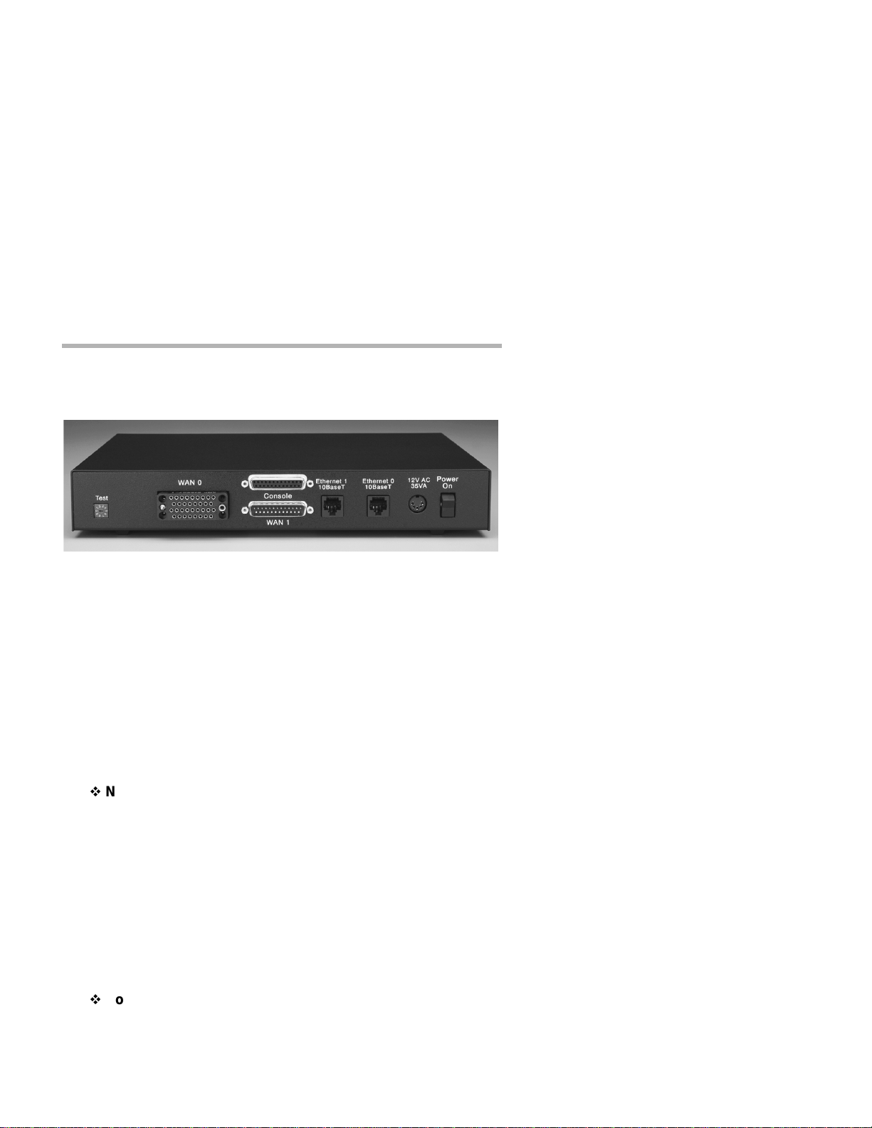
Chapter 3 - Network Installation
MicroRouter 2220R Back Panel
This section of the manual describes how to connect the MicroRouter
2220R to your Ethernet network and your wi de area communications
device(s). In summary, the steps for installation are:
1. Make sure the router is powered down and not plugged to any
power source.
2. Connect the router to the Ethernet networks.
3. Connect the router’ssecondary port to a wide area line communications device (if used).
4. Power up the line communications device (if used).
v
Note: You should either wait to connect a synchronous l ine device
such as a CSU/DSU until after the interface has been configured as a
synchronous port, or power up the router before powering up the
CSU/DSU. (See Chapter 6 - Basic Configuration Guide for more information on configuring the router.)
5. Plug in the power cable and power up the router.
Placing the Router
The MicroRouter 2220R is meant to be left stand-alone on a desktop or
equipment table.
v
Note: When stacking other equipment on the MicroRouter 2220R,
do not exceed 25 pounds of evenly distributed weight on top of the
router. Additional weight may bend the case.
Page 16

10 Chapter 3 - Network Installation
Connecting the Router to the Ethernet
If your twisted-pair hub is already in place, you can connect the router
to an active network without interrupting network activity. The router
must be powered off.
Connecting to Twisted-Pair Ethernet
Before connecting the router to twisted-pair cabling you need an
unshielded twisted-pair cable that is already connected to your
10BaseT-compatible twisted-pair hub.
To connect the router to the twisted-pair network, simply plug the
twisted-pair cable into the RJ-45 Ethernet connector on the back of the
unit.
Connecting a Line Device to the MicroRouter 2220R
The MicroRouter 2220R supports high-speed synchronous operation
over a V.35 connector. It also supports lower s peed synchronous/asynchronous operation over an RS-232 connector.
The MicroRouter 2220R independently supports PPP, Frame Relay and
SMDS link protocols on WAN 0 and PPP and Frame Relay on WAN 1.
Connecting Devices to the V.35 Interface
This interface -- WAN 0 -- can be used to connect to a wide variety of
line communications devices, including those which support either
leased or dialed operation. Examples include leased 56K CSU/DSUs,
switched 56K CSU/DSUs, fractional T1 CSU/DSUs, ISDN Terminal
Adapters, and full T1/E1 rate CSU/DSUs .
You may select either dial-on-demand, redial if down (“always up”
mode), or leased line operation. This interface may also be set to
receive ISDN or switched 56 inco ming calls.
To connect a device, first make sure that both units are powered off.
Then, simply connect a V.35 cable (not supplied) between the router and
the d evice.
Page 17

Chapter 3 - Network Installation 11
Connecting Devices to the RS-232C Interface
This interface -- WAN 1 -- can be used to connect to synchronous or
asynchronous line communications devices at rates up to 256Kbps
(sync), or 230.4 Kbps (async). Examples include modems, leased or
switched 56K CSU/DSUs, and ISDN Terminal Adapters.
L
Note: If connecting to a synchronous device such as a CSU/DSU,
the router must first be configured for synchronous operation before
connecting to the device. See Chapter 6 - Basic Configuration Guide
for configuration information.
You may select either dial-on-demand, always up (i.e., redial if down),
or leased line operation. This interface may also be set to receive ISDN
or switched-56 incoming calls.
To connect a device, first make sure that both units are powered off.
Then, simply connect the supplied RS-232 cable between t he router and
the d evice.
v
Note: The MicroRouter 2220R RS-232 interfaces require that your
asynchronous line communications device be set to supply the RS-232
DCD signal when a connection has been made. A synchronous RS-232
device should be set to provide DSR.
v
Note: The MicroRouter 2220R includes a special cable to facilitate
connections to RS-232 line communications devices. This cable
includes support for several asynchronous and synchronous control
signals. Off-the-shelf cables generally do not support these signals.
Connecting an Out-of-Band Management Console
If you wish to connect an out-of-band management console, use the
supplied cable and connect to the Console interface on the back of the
MicroRouter 2220R. You can use a dumb terminal or a computer
equipped with VT100 terminal emulation.
The default settings for the Console interface are VT100 terminal
emulation, 9600 bps, 8 bits, no parity, 1 stop bit, no Flow Control.
Page 18

12 Chapter 3 - Network Installation
Powering Up the Router
Power up any modem, CSU/DSU, or TA before powering up the router.
This allows the router to immediately sense whether its secondary interface is connected. The exception to this rule is when connecting an
RS232 interface to a CSU/D SU. In such a case, you must power up the
router before
take approximately one minute to become visible to CompatiView.
v
Note: If you want to use Telnet as a management method, you must
first configure an IP address into the router using an out-of-band
console, or reconfigure the IP address on an IP host or workstation on
the same Ethernet segment as the router. See Chapter 5 - Command
Line Management for more information.
powering up the CSU/DSU. At power-up, the router will
Page 19

Chapter 4 - CompatiView SoftwareInstallation 13
Chapter 4 - CompatiView Software Installation
All of the routers in Compatible Systems’ internetworking and VPN
families, including all R ISC Router and MicroRouter models, can be
managedfroma single GUI managementplatformcalledCompatiView.
CompatiView for Windows is included on the CD-ROM which was
shipped with your MicroRouter 2220R.
v
Note: An older version of CompatiView for Mac OS was included
on the CD-ROM shipped with your router, but does not contain some of
the features o f the newest Windows version.
CompatiView for Windows
CompatiView for Windows allows you to manage the MicroRouter
2220R from an IBM-compatible PC running Windows 95/98 or
Windows NT. The PC can either be configured as an IPX client on a
Novell NetWare internet, or as an IP WinSock client on an IP internet.
System R equirements
In order to successfully run C ompatiView for Windows, you need:
• IBM PC or compatible w/486 or later processor
• Microsoft Windows 95/98, or Windows NT installed
• VGA or better monitor
• IP - A WinSock-compatibletransport stack
- and/or -
• IPX - A Netware or Microsoft Client installation
v
Note: To choose the active transport protocol on a Windows
machine which has both IPX and IP installed, select “Options” from the
Administration menu and click the appropriate radio button under
“Default Transport.”
Installation and Operation
The Windows version of the CompatiView program can be found in the
Network Management/CompatiView/Windows directory on the
CD-ROM that was included with your MicroRouter 2220R.
Page 20

14 Chapter 4 - CompatiViewSoftware Installation
Run the auto-installation program (CV5x file) by double-clicking on it.
The installation program will ask you to select (or create) a directory in
which it should locate CompatiView and its associated files and database subdirectory.
Once the installation is complete, double-click on the CompatiView
icon to open the program. For further information on using CompatiView, see the CompatiView Management Software Reference Guide
included with your router.
v
Note: For an up-to-date description of the changes (if any) made to
Windows system files by the installation program, see the
README.TXT file located in the CompatiView installation directory.
Transport Protocols and CompatiView
CompatiView will be able to use the transport protocol (IP or IPX) you
have selected to access Compatible Systems products anywhere on your
internetwork. Depending on your security setup, you may also be able
to use the IP transport option to manage devices across the Internet.
The IP protocol does not provide a method for CompatiView to automatically discover the router. To initially contact the router over IP
using CompatiView, you must first enter a valid IP address into the
router. You can do this either on a console directly connected to the
router or by setting a workstation’s IP address to 198.41.12.2 with a
Class C subnet mask (255.255.255.0) so that it can communicate over
Ethernet with 198.41.12.1 (the shipping default of Ethernet 0). After
setting the router’s IP address, be sure to change the workstation’s
configuration back to its original settings.
The IPX protocol does
the router. Compatible Systems devices are configured to autoseed the
two most common IPX frame types upon startup (802.2 and 802.3
(raw)). If CompatiView has the IPX/SPX protocol selected as its transport, it will be necessary to either power up the router before powering
up the workstation, or reboot the workstation after the router has
completed its boot sequence. This process will ensure that the workstation and the router have the proper IPX network bindings for communication.
allow CompatiView to automatically discover
Page 21

Chapter 5 - Command Line Management 15
Chapter 5 - Command Line Management
The command line interface allows you to configure and monitor the
router in-band via telnet or out-of-band with a terminal connected to the
MicroRouter 2 220R’s Console interface.
v
Note: Proper syntax is vital to effective operation of command line
management. Case is not significant – you may enter commands in
upper case, lower case, or a combination of the two.
Out-of-Band Command Line Management
You can use command line management and text-based configuration
out-of-band as a permanent management tool, or only temporarily in
order to set the router’s IP parameters to allow in-band Telnet access.
In order to access the command line out-of-band, do the following:
1. Set a terminal or a PC equipped with VT100 terminal emulation to
a baud rate of 9600, 8 b its, no parity, 1 stop bit and no Flow Control.
2. Connect it to the router’s Console interface using the cable which
was supplied with the MicroRouter 2220R.
3. Press the <Return> key one or two times.
4. Enter the default password letmein at the password prompt. The
command line interface prompt will appear on the screen.
If you plan to use out-of-band access for ongoing management of your
router, you can find further information on configuring your router in
Chapter 6 - Basic Configuration Guide. Otherwise, see the section
later in this chapter on Setting Up Telnet Operation for information on
setting the router to allow Telnet access from hosts on its network.
Temporarily Reconfiguring a Host for Command Line Management
You can temporarily reconfigure an IP host in order to set the router ’s IP
parameters to allow in-band Telnet access.
If you wish to set the router’s basic IP parameters in this fashion, the
host must be on the s ame Ethernet segment as one of the router’s
Page 22

16 Chapter 5 - Command Line Management
Ethernet interfaces. You can then do the following:
1. Set the host’s IP address to 198.41.12.2, with a Class C subnet
mask (255.255.255.0) and then Telnet to 198.41.12.1.
2. Enter the default password letmein at the password prompt. The
command line interface prompt will appear on the screen.
3. Use the configure command and set the IPAddress, SubnetMask,
and IPBroadcast keywords in the IP Ethernet 0 (and/or Ethernet
1) section.
4. Use the save command to save the changes to the device’s Flash
ROM.
5. Change the host’s configuration back to its original settings.
See the next section (Setting Up Telnet Operation) for information on
setting the router to allow Telnet access from hosts on its network.
Setting Up Telnet Operation
Telnet is a remote terminal communications protocol based on TCP/IP.
With Telnet you can log into and manage the MicroRouter 2220R from
anywhere on your IP internetwork, including across the Internet if your
security setup allows it. To manage the router with Telnet, you must:
1. Run Telnetclient software on your local computer, which will communicate with the Telnet server built into the MicroRouter 2220R.
2. You must also set some basic IP parameters in the router. The
required parameters for Telnet access to an interface are the IP
address, IP subnet mask, and IP broadcast address. There are several ways to set them.
• You may set them using text-based configuration either
out-of-band via the Console interface or in-band via a reconfigured IP host. Instructions for setting up these two methods
were given earlier in this chapter. Once you have set up the
command line interface, do the following:
A. Use the configure command and set the IPAddress,
SubnetMask,andIPBroadcastkeywords in the IP
Ethernet 0 (and/or Ethernet 1) section.
B. Use the savecommand to save the changes to the device’s
Flash ROM.
• You may also use CompatiViewfrom a reconfigured IP host (if
using the IP transport protocol), or anywhere on your network
Page 23

Chapter 5 - Command Line Management 17
(if using the IPX transport protocol). Instructions for these
two methods are given in Chapter 4 - CompatiView Software
Installation.
• With CompatiView, basic IP parameters can be set using the
TCP/IP Routing: Ethernet 0 Dialog Box. Use the Save
to/Device option under the File menu to save the changes.
After you have set these IP parameters and saved the changes, you can
use Telnet to access the router from any node on your IP network.
Invoke the Telnet client on your local host wi th the IP address of the
router you wish to manage.
Page 24

.
Page 25

Chapter 6 - Basic Configuration Guide 19
Chapter 6 - Basic Configuration Guide
This chapter briefly explains the major parameters that must be set in
order to use the router.
Detailed information on the meaning of the router’s parameters is
provided in the CompatiView Management Software Reference Guide
and the Text-Based Configuration and Command Line Management
Reference Guide. You should use this list as a starting point to look up
more specific information in the other documents.
If you need more general information on IP, IPX, AppleTalk, DECnet,
or wide area protocols, see the Appendices in the CompatiView
Management Software Reference Guide.
There are a number of parameter settings which are optional, in the
sense that they are not required for all installations. These settings are
not covered in this chapter.
In this chapter:
CV =CompatiView
TB = Text-Based Configuration
In order to successfully connect to an Internet Service Provider (ISP),
you must use router configuration parameters which will be provided by
the technical staff of the ISP. These parameters must include all I P
addresses, WAN settings, and any applicable authorization routines.
Please check with your ISP before
ration of your MicroRouter 2220R.
configuring or changing the configu-
v
Note:This Basic Configuration Guide does not include information
on setting up packet filters for using the router as a Firewall. See the
CompatiView Management Software Reference Guide or Text-Based
Configuration and Command Line Management Reference Guide
regarding IP packet filters for more information.
Page 26

20 Chapter6 - Basic ConfigurationGuide
Ethernet Interface Configuration
Ethernet interfaces are considerably easier t o set up than wide area
interfaces s ince there are fewer choices that need to be made regarding
communications protocols and parameters. We recommend that you
begin by configuring any Ethernet interface parameters before configuring WAN interface parameters.
IP Protocol
Required for IP
These parameters set the basic address characteristics of the interface.
They provide enough information for another IP node to find the interface (such as a Telnet client), but not enough information for routing to
take place.
•IPAddress
• IP Subnet Mask
• IP Broadcast Address
CV: Use the TCP/IP Routing: Ethernet D ialog Box to s et these param-
eters.
TB: Use the configure command and the IPAddress, SubnetMask,
and IPBroadcast keywords in the IP Ethernet 0 (and/or
Ethernet 1) section.
Suggested for IP
These parameters help supply information about the segment to which
the interface is connected. With this information, routing can take
place.
• Set IP RIP 1 or IP RIP 2
• IP Static Routes
CV: Use the TCP/IP Routing: Ethernet Dialog Box to set RIP, and the
IP Static Routing Dialog Box (under Global/IP Static Routes) to
set static routes.
TB: Use configure and set the RIPVersion keyword for the IP
Ethernet 0 (and/or Ethernet 1) section. Use edit config and add
static rout es in the IP Static section.
Page 27

Chapter 6 - Basic Configuration Guide 21
IPX Protocol
Required for IPX
There are generally no required changes from t he shipping Ethernet
configuration for IPX. The Ethernet interface will autoconfigure to use
the two most common IPX frame types, and will autoadapt to conditions on the Ethernet.
Suggested for IPX
You may want to set your own network numbers, rather than using the
autoconfigured values. You may also want to turn off unused frame
types.
CV: Use the IPX Routing: Ethernet 0 Dialog Box.
TB:Useconfigure and set keywords in the IPX Ethernet 0 (and/or
Ethernet 1) section.
AppleTalk Protocol
Required for AppleTalk
There are generally no required changes from t he shipping Ethernet
configuration for AppleTalk. The Ethernet interface will autoconfigure
to use AppleTalk Phase 2, and will autoadapt to conditions on the
Ethernet.
Suggested for AppleTalk
You may want to set your own network numbers, rather than using the
autoconfigured values. You may also want to use more meaningful
zone names.
CV: Use the AppleTalk Routing: Ethernet 0 Dialog Box.
TB: Use configure and set keywords in the AppleTalk Phase 2
Ethernet 0 (and/or Ethernet 1) section.
DECnet Protocol
Required for DECnet
The router’s shipping configuration does not have DECnet turned on.
You must turn it on and set several DECnet parameters.
• Set DECnet on (globally, and for this port)
• Set DECnet area
• Set DECnet node
Page 28

22 Chapter6 - Basic ConfigurationGuide
CV: Use the DECnet Routing Dialog Box (under Global/DECnet
Routing) and the DECnet: Ethernet Dialog Box.
TB: Use configure and set the Enabled, Area,andNode keywords in
the DECnet Global section.
v
Note: Setting DECnet on for any port with the command line also
sets DECnet on globally. In CompatiView you must set a global
parameter and a port-specific parameter.
Suggested for DECnet
Setting the parameters above should be adequate for most installations.
WAN Interface Configuration
In order to use a WAN interface, you may first need to set some physical parameters and then s et up the link and protocol parameters.
There are a few differences between the capabil ities of the V.35 WAN
interface and the RS-232 WAN interface. The V.35 interface can only
be run synchronously, at rates up to 2 Mbps per second. The RS-232
interface can be run synchronously or asynchronously, at rates up to
256Kbps (sync) or 230.4Kbps (async).
Physical Communications Settings
You may need to set the baud rate, sync/async operation, and o ther
physical communications parameters for the WAN interface. These
parameters will depend on the line communications device you are
using.
v
Note: Frame Relay and SMDS are presently supported in the
MicroRouter 2220R only via synchronous operation. An external
clock signal is generated for Frame Relay.
CV: Use the Physical Configuration: WAN Dialog Box.
TB: Use configure and set the LinkType keyword or other keywords
in the RS232 Interface WAN 0 (and/or WAN 1) section.
Page 29

Chapter 6 - Basic Configuration Guide 23
PPP Configuration
This section covers the settings required for PPP (point-to-point)
protocol operation of the WAN interfaces.
Link Configuration
Required for Dedicated/Leased Line Operation
Dedicated line operation is the simplest to set up.
• Set Dedicated connection
• Set PPP connection
CV: Use the Link Configuration: WAN 1 Dialog Box.
TB: Use configure and set the Mode and ConnectMode keywords in
the Link Config WAN 0 (and/or WAN 1) section.
Suggested for Dedicated/Leased Line Operation
Dedicated line operation generally does not require additional parameters for operation.
Required for Dial-On-Demand Operation
Incoming dial-on-demand operation requires only slightly more information than dedicated line setup. Outgoing dial-on-demand requires
additional information (see the suggested settings below).
• Set dial-up connection
• Set PPP connection
• Set to allow dial-in and/or dial-out
CV: Use the Link Configuration: WAN Dialog Box.
TB: Use configure and s et the Mode, ConnectMode, DialIn and/or
DialOut keywords in the Link Config WAN 0 (and/or WAN 1)
section.
Suggested for Dial-On-Demand Operation
This mode of operation is only supported on the WAN 1 RS-232 interface. Outgoing dial-on-demand requires some additional information.
• Create dial-out script
• Set dialing method
• Set dial-out script to be used
• Set inactivity time
CV: Use the Link Configuration:WAN 1 Dialog Box to set the dialing
Page 30

24 Chapter6 - Basic ConfigurationGuide
method and to select a chat script (once you have created one).
Use the WAN Chat Scripts Dialog Box (under Global/WAN Chat
Scripts) to create your chat script.
TB: Use configure and then set the Dialing, DialOutScript,and
DropInactkeywords in the Link Config WAN 1 section. Use
edit config and create a Chat section to contain your dialing
script.
IP Protocol
Required for IP
WAN interfaces which are set for PPP operation do not generally use an
IP address. They are set to act as an “unnumbered interface.” In this
mode of operation, there are no required settings.
Suggested for IP
These parameters help supply information about the segment to which
the interface is connected. With this information, routing can take
place.
• Set IP RIP 1 or IP RIP 2
• IP Static Routes
CV: Use the TCP/IP Routing: WAN Dialog Box to set RIP or OSPF,
and the IP Static Routing Dialog Box (under Global/IP Static
Routes) to set static routes.
TB:Useconfigureand set the RIPVersionkeywordin the IP WAN0
(and/or WAN 1) section. Add static routes and a default router
using the edit config IP Static command.
v
Note: If you set RIP to “on” for a dial-on-demand link, you must
also set the update method to triggered to prevent the link from being
brought up by transmission of RIP information. You should only use
triggered operation when you are connecting to another Compatible
Systems router at the other end of the link.
IPX Protocol
Required for IPX
WAN interfaces which are set for PPP operation do not generally use an
IPX address. They are set to act as an “unnumbered interface.” In this
mode of operation, there are no required settings.
Page 31

Chapter 6 - Basic Configuration Guide 25
Suggested for IPX
If you plan to use dial-on-demand for this link, you should set the
update method to “triggered” to avoid the link being brought up by
transmission of IPX RIP information. You should only use triggered
operation when you are connecting to another Compatible Systems
router at the other end.
When you set up an on-demand link with IPX, you should carefully
monitor link usage to determine whether the link is being activated only
when it is needed. Additional router configuration will be required for
many networks in order to achieve optimal link usage.
• Set update method
CV: Use the IPX Routing: WAN Dialog Box.
TB: Use configure and set the Updates keyword in the IPX WAN 0
(and/or WAN 1) section.
AppleTalk Protocol
Required for AppleTalk
WAN interfaces which are set for PPP operation do not generally use an
AppleTalk address. They are set to act as an “unnumbered interface.”
In this mode of operation, there are no required settings.
Suggested for AppleTalk
If you plan to use dial-on-demand for this link, you should set the
update method to “triggered” to avoid the link being brought up by
transmission of AppleTalk RTMP information. You should only use
triggered operation when you are connecting to another Compatible
Systems router at the other end.
When you set up an on-demand link with AppleTalk, you should carefully monitor link usage to determine whether the link is being activated
only when it is needed. Additional router configuration will be required
for many networks in order to achieve optimal link usage.
• Set update method
CV: Use the AppleTalk Routing: WAN Dialog Box.
TB: Use configure and s et the Updates keyword in the AppleTalk
WAN 0 (and/or WAN 1) section.
Page 32

26 Chapter6 - Basic ConfigurationGuide
DECnet Protocol
Required for DECnet
The router’s shipping configuration does not have DECnet turned on.
In order to be used, DECnet must be turned on both globally and for a
particular port.
WAN interfaces which are set for PPP dial-on-demand operation should
have their DECnet hello timers an d DECnet routing timers set for a
fairly long period, since the link will be brought up when this information is transmitted.
Because of the need to regularly bring the link up to exchange routing
information, on-demand operation using DECnet is not recommended.
• Set DECnet on (globally, and for this port)
• Set DECnet area
• Set DECnet node
• Set hello timer
• Set routing timer
CV: Use the DECnet Routing Dialog Box (under Global/DECnet
Routing) and the DECnet: WAN Dialog Box.
TB: Use configure and set the HelloTimer and Mode keywords in
the DECnet WAN 0 (and/or WAN 1) section. Use configure and
set the Enabled, Area,andNode keywords in the DECnet
Global section.
v
Note: Setting DECnet on for any port with the command line also
sets DECnet on globally. In CompatiView you must set a global
parameter and a port-specific parameter.
Suggested for DECnet
Setting the parameters above should be adequate for most installations.
Page 33

Chapter 6 - Basic Configuration Guide 27
Frame Relay Configuration
This section covers the settings required for Frame Relay operation of
the Mi croRouter 2220R WAN interfaces. In general, the parameters
listed here should be set for each WAN interface on which you plan to
use Frame Relay.
Link Configuration
Frame Relay is presently supported in the MicroRouter 2220R only via
dedicated line operation.
• Set Dedicated connection
• Set Frame Relay connection
CV: Use the Link Configuration: WAN Dialog Box.
TB: Use configure to set the Mode and ConnectMode keywords in
the Link Config WAN 0 (and/or WAN 1) section.
Suggested for Dedicated/Leased Line Operation
Dedicated line operation generally does not require additional parameters for operation.
Frame Relay DLCI Mappings
If you are connecting to another Compatible Systems router,this information is not required for Frame Relay operation. Compatible Systems
uses IARP (Inverse Address Resolution Protocol) to dynamically
generate this information. Toconnect to other vendors’ routers which
do not support IARP, you must provide DLCI-to-protocol mapping
information.
v
Note: Many Internet Service Providers (ISP’s) do not support IARP
as a default. If one of your MicroRouter 2220R interfaces will be
connected to an ISP via Frame Relay, check with your ISP technical
staff on whether or not you must manually enter DLCI information.
CV: Use the DLCI Mapping Database Dialog Box (under WAN>Link
Configuration>DLCIbutton).
TB: Use configure and set the DLCI keyword in the Frame Relay
WAN 0 (and/or WAN 1) section.
Page 34

28 Chapter6 - Basic ConfigurationGuide
IP Protocol
Required for IP
There are two ways to set up Frame Relay. One is to s et the WAN interface as a “numbered interface.” This means that the interface (and thus
the Frame Relay network) will have an IP address, subnet mask, etc.
The o ther is to set it as an unnumbered interface and specify that the
link is point-to-point Frame Relay and set the local DLCI.
Required for IP Numbered Interface
• IP numbered interface
•IPaddress
• IP subnet mask
• IP broadcast address
CV: Use the TCP/IP Routing: WAN D ialog Box.
TB: Use the configure command and the Numbered, IPAddress,
SubnetMask,andIPBroadcastkeywords in the IP WAN 0
(and/or WAN 1) section.
Required for IP Unnumbered Interface
• IP unnumbered interface
• Point-to-Point Frame Relay
• Local DLCI
CV: Use the TCP/IP Routing: WAN D ialog Box.
TB:Usetheconfigure command and the Numbered, PointToPoint-
Frame,andInterfaceDLCI keywords in the IP WAN 0 (and/or
any other port you wish to configure) section.
Suggested for IP
These parameters help supply information about the segment that the
interface is connected to. With this information, routing can take place.
• Set IP RIP 1 or IP RIP 2
• IP Static Routes
CV: Use the TCP/IP Routing: WAN Dialog Box to set RIP or OSPF,
and the IP Static Routing Dialog Box (under Global/IP Static
Routes) to set static routes.
TB:Useconfigureand set the RIPVersionkeywordin the IP WAN0
(and/or WAN 1) section. Add static routes and a default router
using the edit config IP Static command.
Page 35

Chapter 6 - Basic Configuration Guide 29
IPX Protocol
Required for IPX
Frame Relay operation requires that the WAN interface is set to be a
“numbered interface.” This means that the interface (and thus the
Frame R elay network) must have an IPX network number.
• IPX numbered inte rface
• IPX Network Number
CV: Use the IPX Routing: WAN Dialog Box.
TB:Useconfigure and set the Numbered and Net keywords in the
IPX WAN 0 (and/or WAN 1) section.
Suggested for IPX
The settings above are all that is generally required for IPX operation
over Frame Relay.
AppleTalk Protocol
Required for AppleTalk
Frame Relay operation requires that the WAN interface is set to be a
“numbered interface.” This means that the interface (and thus the
Frame Relay network) musthave an AppleTalk network number and the
interface must have an AppleTalk node number.
• AppleTalk numbered interface
• AppleTalk Network Number
• AppleTalk Node Number
•AppleTalkZoneName
CV: Use the AppleTalk Routing: WAN Dialog Box.
TB: Use configure and set the Numbered, NetLower,andDefZone
keywords in the AppleTalk WAN 0 (and/or WAN 1) section.
Suggested for AppleTalk
The settings above are all that is generally required for AppleTalk operation over Frame Relay.
DECnet Protocol
Required for DECnet
WAN interfaces which are set for Frame Relay operation do not need
Page 36

30 Chapter6 - Basic ConfigurationGuide
any additional parameters set in order to function.
DECnet must be turned on globally, and turned on for a particular port,
in order to be used.
WAN interfaces which are set for Frame Relay operation do not need
any additional parameters set in order to function.
• Set DECnet on (globally, and for this port)
CV: Use the DECnet Routing Dialog Box (under Global/DECnet
Routing) and the DECnet: WAN Dialog Box.
TB: Use configureand set the Mode keyword in the DECnet WAN0
(and/or WAN 1) section.
v
Note: Setting DECnet on for any port with the command line also
sets DECnet on globally. In CompatiView you must set a global
parameter and a port-specific parameter.
SMDS Configuration
This section covers the settings required for SMDS (Switched
Multi-megabit Data Service) operation of the MicroRouter 2220R WAN
0 interface (IP only). SMDS is a connectionless, packet-switched
service that offers LAN -to-LAN connectivity across a wide area atup to
1.544 Mbps.
v
Note: The IP protocol settings and the physical communication
settings are the same as they would be for Frame Relay operation. The
only parameters which should be set differently for SMDS are the Link
Configuration and the SMDS addressing section.
Link Configuration
SMDS is presently supported in the MicroRouter
1250i1270i2250R2270R only via dedicated line operation.
• Set Dedicated connection
• Set SMDS connection
CV: Use the Link Configuration: WAN Dialog Box.
TB:Useconfigure and then set the Mode and ConnectMode
keywords in the Link Config WAN 0 (and/or WAN 1) section.
Page 37

Chapter 6 - Basic Configuration Guide 31
SMDS Addressing
Many of these parameters will be given to you by your service provider.
CV: Use the Link Configuration: WAN Dialog B ox and select SMDS
from the Link Type pull-down menu. Then click on the SMDS
buttontosetaddresses.
TB: Use configure and set the StationAddress, IPMulticast and
PollingFrequency keywords in the SMDS WAN 0 (and/or
WAN 1) section.
Saving a Configuration File to Flash ROM
Once a configuration is complete, you can save it to the router’s Flash
ROM. Until saved, all changes are made in a separate buffer and the
actual router interfaces run as before the changes were made.
CV: Use the Save to/Device option from the File menu.
TB: Use the save command.
Page 38

.
Page 39

Appendix A - Shipping Defaults 33
Appendix A - Shipping Defaults
Default Password
•letmein
Ethernet Interfaces
IP Routing Defaults
• Off, both interfaces
IP Bridging Defaults
• On, both interfaces
• Address: 198.41.12.1
• Subnet Mask: 255.255.255.0
• Broadcast Address: 198.41.12.255
•IPRIPoff
IPX Routing Defaults
• 802.3 on, autoseeding, both interfaces
• 802.2 on, autoseeding, both interfaces
• Type II off, both interfaces
• 802.2 SNA P off, both interfaces
IPX Bridging Defaults
• Off, both interfaces
AppleTalk Routing Defaults
• Phase I off, both interfaces
• Phase II on, autoseeding, both interfaces
AppleTalk Bridging Defaults
• Off, both interfaces
DECnet Defaults
• Off, both interfaces
Page 40

34 Appendix A - Shipping Defaults
WAN Interfaces
IP Defaults
•On
• Unnumbered interface
•RIPoff
• Van Jacobson compression off
IPX Defaults
•On
• Unnumbered interface
AppleTalk Defaults
•On
• Unnumbered interface
DECnet Defaults
•Off
V.35 (WAN 0) Link & Physical Defaults
• PPP
• Dedicated
• Sync, external clock
RS-232 (WAN 1) Link & Physical Defaults
• PPP
• Dial-in
• Async @ 115.2Kbps
• Hardware flow control
Page 41

Appendix B - Connector and Cable Pin Outs 35
Appendix B - Connector and Cable Pin Outs
Pin Outs for V.35 Female Connector (DTE)
V.35 (DTE) Signal
A Chassis Ground ↔
B Signal Ground ↔
C Request to Send →
DCleartoSend ←
E Data Set Ready ←
F Receive Line Signal Detect ←
H Data Terminal Ready →
J Local Loopback →
PTxData →
RRxData ←
STxData →
TRxData ←
UTxClockOut →
VRxClockIn ←
WTxClockOut →
XRxClockIn ←
YTxClockIn ←
AA Tx Clock In ←
Page 42

36 AppendixB - Connector and Cable Pin Outs
Pin Outs for DB-25 Maleto DB-25 Female RS-232 Data & Console Cable
The cable supplied with the MicroRouter 2220R is twenty-five conductors, straight through. Connections on both the auxiliary interface and
the data interface follow the standard RS-232 pin outs. Note that the
data interface may be set for synchronous operation and in this mode
the data interface will use the clock lines provided by RS-232.
Page 43

Appendix C - LED Patterns and Test Switch Settings 37
Appendix C - LED Patterns and Test Switch Settings
MicroRouter 2220R LED Patterns
The MicroRouter 2220R uses a number of light patterns on its front
LED bars to indicate operating conditions.
Power On, No Traffic
The router will scan through the lefttwo (Ethernet) LED bars, from lef t
to right, illuminating one element at a time.
v
Note: Lights 1 and 10 on each bar are directly connected to the
router’s 10BaseT interface and indicate 10BaseT link (1) and 10BaseT
polarity (10).
Ethernet Traffic Indicators (Ethernet LED Bars)
Scan from 2 to 5: Ethernet transmit packet
Scan from 9 to 6: Ethernet receive packet
Other Indicators (on All LED Bars)
Transmit and receive packets - per WAN interface as marked on front
label.
5,6 flashing: Router stacks starting up
3,4 & 7,8 flashing: No OS loaded. Running from ROM.
5,6 on solid, 2 (bars 1 & 3) and 9 (bars 2 & 4) flashing : Erasing OS in
Flash ROM
4,5,6,7 on solid, 2 (bars 1 & 3) and 9 (bars 2 & 4) flashing : Erasing
config in Flash R OM
Scanning from 2 to 9 (bars 1 & 3), and scanning from 9 to 2 (bars 2 &
4): Flash ROM erase due to switch setting five or six is complete. Set
switch to zero and cycle power.
Panic Indicators
Any continuous flashing pattern not n oted above may be caused by a
software “panic.” This is a sign that a condition has been detected that
the software does not know how to deal with: either an unusual
network condition, or a hardware failure. Please call Compatible
Systems Technical Support if your router shows a software panic.
Page 44

38 Appendix C - LED Patterns and Test Switch Settings
MicroRouter 2220R Switch Settings
0 Normal Operation
1Unused*
2Unused*
3 Run Boot ROM Downloader
4Unused*
5 Erase Flash ROM (OS and Configuration)
6 Erase Flash ROM (Configuration Only)
7Unused*
8Unused*
9 Allow letmein password for 5 minutes after powerup
M
Caution: Settings marked with an asterisk may erase your Flash
ROM. Please do not use these settings without first contacting
Compatible Systems Technical Support.
Page 45

Appendix D - Downloading Software From CompatibleSystems 39
Appendix D - Downloading Software From Compatible Systems
We make the latest versions of operating software for all Compatible
Systems products available at our Web site. The latest version of
CompatiView management software is also available.
To download software, follow the instructions below.
1. Use your browser to access http://www.compatible.com/, and find
the link on our home page to “Software Downloads.”
2. Select the product and software version you want, and click on the
appropriate file to download it.
v
Note: Uncompressed downloads (suitable for TFTP and Compa-
tiView Windows downloading) are stored as .DLD files. Self-extracting
Windows compatible style files (and CompatiView for Windows itself)
are stored as .EXE files. Self-extracting Macintosh style files are stored
as .sea.bin (MacBinary format) and/or .sea.hqx files.
v
Note: These files are also accessible directly via Anonymous FTP at
ftp.compatible.com/files/.
Page 46

.
Page 47

Appendix E - Terms and Conditions 41
Appendix E - Terms and Conditions
Compatible Systems Corporation (Compatible Systems) offers to sell only
on the condition that Customer’s acceptance is expressly limited to Compatible Systems’ terms and conditions of sale. Compatible Systems’ acceptance of any order from Customer is expressly made conditional on assent to
these terms and conditions of sale unless otherwise specifically agreed to in
writing by Compatible Systems. In the absence of such agreement, commencement of performance or delivery shall be for Customer’s convenience
only and shall not be construed as an acceptance of Compatible Systems’
terms and conditions. If a contract is not ear lier formed by mutual agreement in writing, Customer’s acceptance of any goods or services shall be
deemed acceptance of the terms and conditions stated herein.
1. Warranty. Compatible Systems warrants to the Customer and to all persons who purchase Products from the Customer during the Warranty terms
(“subsequent purchasers”), that, for a period of three (3) years from the date
(the “shipping date”) on which Compatible Systems ships the Products to the
Customer: (a) the Product meets, in all material respects, all specifications
published by Compatible Systems for such Products as of the shipping date;
(b) the Products are free from all material defects in materials and workmanship under normal use and service; and (c) that as a result of the purchase of
the Products from Compatible Systems, the Customer will have good title to
the Products, free and clear of all liens and encumbrances.
Compatible Systems’ obligations pursuant to this Warranty, and the sole
remedies of the Customer and of any subsequent purchaser, shall be limited
to the repair or replacement, in Compatible Systems’ sole discretion, of any
of the Products that do not conform to this Warranty.
This Warranty shall be invalidated if the Products: (a) have not been
installed, handled, or used in accordance with Compatible Systems recommended procedures; (b) have been damaged through the negligence or abuse
of the Customer or of any subsequent purchasers; (c) are damaged by causes
external to the Products, including (without limitation) shipping damage,
power or air conditioning failure, or accident or catastrophe of any nature;
and (d) have been subjected to repairs or attempted repairs by any person
other than Compatible Systems (or an authorized Compatible Systems service technician).
Page 48

42 Appendix E - Terms and Conditions
To obtain service under this Warranty, the Customer (or subsequent purchaser, if applicable) must follow the procedures outlined below, under
“Product Return Policy.”
THE WARRANTIES SET FORTH IN THESE TERMS AND CONDITIONS ARE IN LIEU OF ALL OTHER WARRANTIES, EXPRESSED
OR IMPLIED. WITHOUT LIMITATION ON THE GENERALITY OF
THE FOREGOING SENTENCE, COMPATIBLE SYSTEMS EXPRESSLY
DISCLAIMS AND EXCLUDES ALL IMPLIED WARRANTIES OF
MERCHANTIBILITY AND OF FITNESS (GENERALLY OR FOR A
PARTICULAR PURPOSE).
2. Shipments. All delivery indications are estimated and are dependent in
part upon prompt receipt of all necessary information to service an order.
Compatible Systems shall not be liable for any premium transportation or
other costs or lossesincurred by Customer as a result of Compatible Systems
inability to deliver Product in accordance with Cust omer’s requested delivery dates. All shipments by Compatible Systems are made F.O.B. factory
(Boulder,Colorado); risk of loss shallpasstoCustomerat point of shipment.
Unless specified by the Customer, Compatible Systems will select the mode
of transportation for each order. Compatible Systems reserves the right to
make deliveries in installments. Partial shipments are subject to the terms of
payment noted below. Compatible Systems reserves the right to allocate
inventory and production if such allocation becomes necessary.
3. Payment Terms. Payment shall be made prior to shipment or upon
delivery, unless otherwise agreed to in writing. Payment shall not constitute
acceptance o f the goods.
4. Force Majeure. All orders accepted by Compatible Systems are subject
to postponement or cancellation for any cause beyond the reasonable control
of Compatible Systems, including without limitation: inability to obtain
necessary materials and components; strikes, labor disturbances, and other
unavailability of workers; fire, flood, and other acts of God; war, riot, civil
insurrection, and other disturbances; production or engineering difficulties;
and governmental regulations, orders, directives, and restrictions.
5. Product Return Policy. Prior to shipping any Product to Compatible
Systems, the Customer must contact CompatibleSystems Technical Support
(by letter or telephone) with the following information: (a) reason for return;
(b) quantity, description, and model number, and (if applicable) serial num-
Page 49

Appendix E - Terms and Conditions 43
ber of each item being returned; (c) original Compatible Systems Sales
Agreement number; and (d) any special instructions. Upon receipt of this
information, Compatible Systems will issue an RMA (“Return Material
Authorization”) number and any required U.S. Customs identification to
assure correct identification of the Customer and to insure prompt and accurate processing.
6. Limitation of Remedies. Compatible Systems’ liability for all claims
brought pursuant to or in connection with this agreement, including the purported breach hereof, shall be limited: (a) in the case of claims for breach of
warranty, to compliance w ith the repair or replacement provisions of the
warranty, and (b) in all other cases (including any claim that the warranty
failed of its essential purpose), to actual damages of the Customer (or, if
appropriate, of the subsequent purchaser). IN NO EVENT SHALL COMPATIBLE SYSTEMS BE LIABLE FOR ANY SPECIAL, CONSEQUENTIAL, OR INCIDENTAL DAMAGES ARISING OUT OF THE SALE,
USE, INSTALLATION OR OPERATION OF THE PRODUCTS,
WHETHER A CLAIM IS BASED ON STRICT LIABILITY, BREACH OF
WARRANTY, NEGLIGENCE, OR ANY OTHER CAUSE WHATSOEVER, WHETHER OR NOT SIMILAR. This limitation on remedies shall
apply even if Compatible Systems is advised of the possibility and nature of
any special, consequential, or incidental damages.
7. Governing Law; Merger. This agreement and all Termsand Conditions
hereof shall be governed by, and construed in accordance with the i nternal
laws of the State of Colorado. Except as superseded by a separate written
contract signed by both Compatible Systems and the Customer, superseding
all prior negotiations or offers, written or oral, this agreement may be
amended only in writing, signed by an authorized officerof Compatible Systems.
 Loading...