

Page 1
Fly at your own risk !
Assembly Manual
Version 2.0
Created : 10/26/2009
Features :
- Best 3D Performance
- Precision ECCPM 120° Metal Swashplate
- Easy Maintenance
- 80% Preassembled
- Low Parts Count
- Wear Resistant Parts
Equipped with extra Strong Frames, Aluminum Rotor Head, Aluminum Tail Rotor and a
Metal Swashplate the Atom 500 not only looks great but is long lasting.
Copyright Compass Model 2008
As we continue to improve our products; this manual may not reflect all recent product amendments.
For more information, please refer to www.compassmodel.com
Page 2

Academy of Model Aeronautics
5151 East Memorial Drive
Muncie, IN47302
Introduction
Warning
Warranty
AMA Information
The warranty covers defects in material or workmanship or missing components to the original purchaser for 30 days from
the date of purchase. Compass Model Ltd will replace or repair, at our discretion, the defective or missing component.
Defective components must be returned to our Distributor prior to replacement.
Any part, which has been improperly installed, abused, crash damaged or altered by unauthorized agencies is not covered.
Under no circumstances will the buyer be entitled to consequential or incidental damages. The components used in this kit
are made fromspecial materials designed for special applications and design strengths. Werecommend that all replacement
parts be original parts manufactured by Compass Model Ltd to ensure proper and safe operation of your model. Any part
used which wasmanufactured by any firmother than Compass Model Ltd VOIDS all warrantiesof this product by Compass
Model Ltd.
We strongly encourageallprospectiveandcurrent R/C aircraft pilots to join the Academy of Model Aeronautics. TheAMA is
a non-profit organization that provides services to model aircraft pilots. As an AMA member, you will receive a monthly
magazine entitled Model Aviation, as well as liability insurance plan to cover against possible accident or injury. All AMA
charter aircraft clubs require individuals to hold a current AMA sporting license prior to operation of their models. For
further information, you can contact theAMAat:
Congratulations on your purchase of the Compass Model Atom 500 Electric Powered Helicopter.This model has been
designed using the latest in state-of-the-art design technology. To achieve the best performance and reliability from this
model, please read through these instructions carefully so you become familiar with the contents of this kit before assembly.
Warranty Procedures
Mail all warranty information within 15 days of original purchase date. If service is required, send the component in
question (if not missing) together with a photocopy of your bill of sale and an accurate description of the problem and part.
Ship components fully insured and prepaid. CompassModel Ltd isnot responsible for anyshipping damages. We will, at our
discretion, notify you of any costs involved, or ship it COD. You are required to pay all postage, shipping and insurance
charges.
R/C Helicopter Safety
A model helicopter must be built exactly in accordance with the assembly instructions. Compass Model Ltd has spent much
time and efforts refining this product to make it reliable in operation and easy tobuild. Vibration and stresslevels are high and
all fasteners and attachments must be secure for safe operation. Safe operation is the responsibility of the builder/flyer and
starts with careful construction and continues with selection and installation of reliable radio equipment and motor/engine.
The need for safety is nowhere greater than at the flying field. A number of guidelines for safe flight have been developed by
experienced flyers and are set down here. It is urged that they be read, understood and followed.
each country has his own security application which cannot be laid down here so prior to any flight request the
rules to apply in your country/Flying field.
Attention:
The radio-controlled model helicopter contained in this kitis not a toy, but a sophisticated piece of equipment.This product
is not recommended foruse bychildren. Radio-controlled models such asthis are capable of causing both property damage
and/or bodily harm to both the operator/assembler and/or spectator if not properly assembled and operated. Compass
Model Ltd. assumes no liability for damagethat could occurfrom the assembly and/oruse/misuse of thisproduct. Although
theAtom 500is powered bya quiet,smooth-running electric motor, it shouldbe assembledand operated withthe samecare
as its larger glow engine counterparts.When operating yourAtom 500, please exercise caution and safety.
Page 3
• Fly only at approved flying fields and obey field regulations.
• Follow frequency control procedures. Interference can be dangerous to all.
• Obtain assistance from experienced pilots.
• The Guidance provided by experienced pilots is valuable and sometimes necessary.
• Know your radio. Check all transmitter functions before each flight.
• Be aware that rotating blades are very dangerous and can cause serious injury.
• Never fly near or above spectators or other modelers.
• Do not fly r/c helicopter models near buildings, high voltage cables, trees or other obstacles.
• If a beginner, get help trimming the model first and flight training later.
• Don’t “track” the main blades by holding the tail boom. This is a temptation to builders who cannot hover yet and is very dangerous.
• Follow all recommended maintenance procedures for model, radio and motor.
• Only turn off the radio after the engine is shut down.
Length: up to 430mm
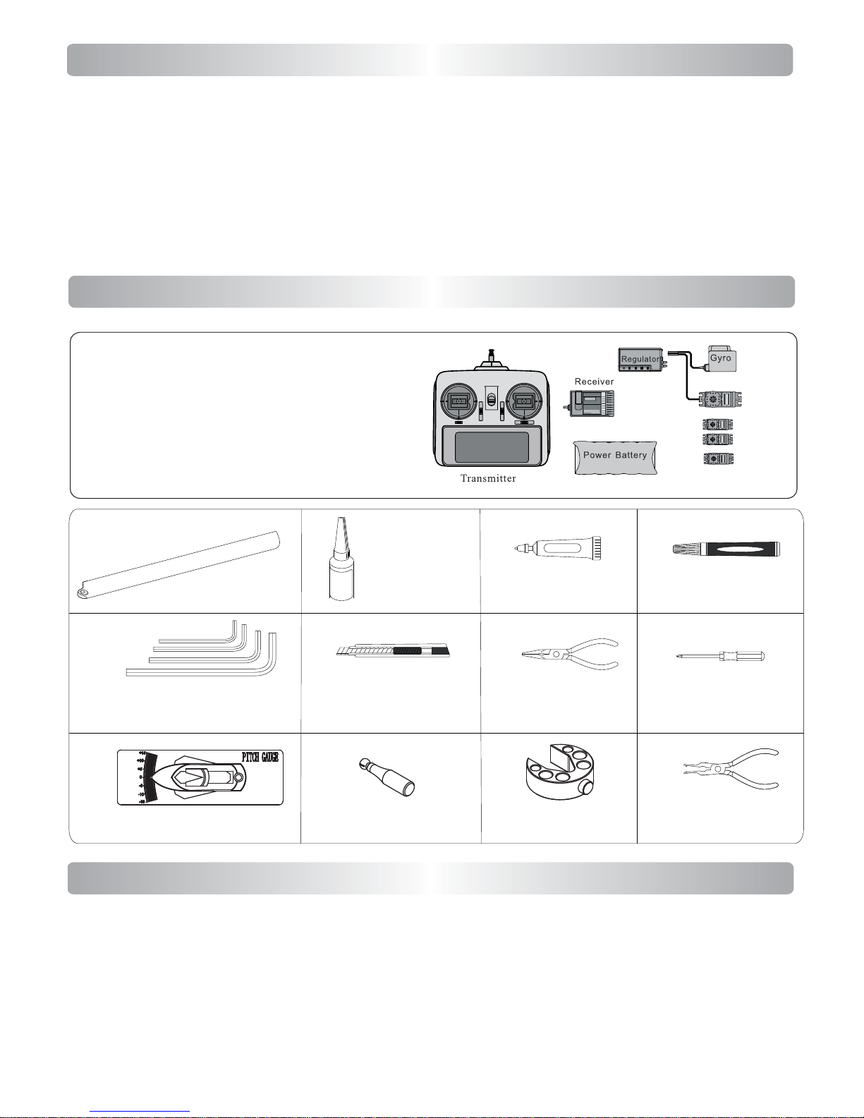
Necessary Items
Bearing Retainer
6 channel or up radio and receiver.
3 mini servos.
1 gyro with rudder servo.
6S LiPo battery 2100mah~3300mah.
or 2 pack 3s LiPo battery with same capacity.
Mini Servos
Grease
Needle Nose Pliers
Screw Driver
Hex Wrench Set
(1.5mm,2mm,2.5mm,3mm)
Cutter Knife
Main Rotor
Pitch Gauge
Ball Link Sizing Tool Ball Plier
When first opening your Atom kit, you will notice that all of the parts are packaged and numbered to coordinate with the
assembly step numbers of this instruction manual. All small hardware (nuts, bolts, washers, etc.) for each step are packaged
separately within the main parts bags. When beginning a section, you will need to open only the bag with the corresponding
number to the section you are about to start. It is suggested that you place all ofthe hardware in an open container (e.g., servo
case) during assembly so as not to lose any of the small parts. It may also be helpful to familiarize yourself with the various
sizes of screws, bolts, nuts,etc., asillustrated in theappropriate assemblysection beforeyou beginassembly. In most cases, at
the end of each assembly section, there should be no parts remaining. Great care has been taken in filling the bags with the
correct quantity of parts and hardware for each section. However, occasional mistakes happen. In the event that you find a
parts shortage or are in need of technical assistance, please contact your local Compass Model parts dealer.
Preassembly Information
In order to operate this model, you need to purchase the following items not kit-included.
Swash PlateTool
Guidelines for Safe R/C Helicopter Flight
Threadlock
Page 4
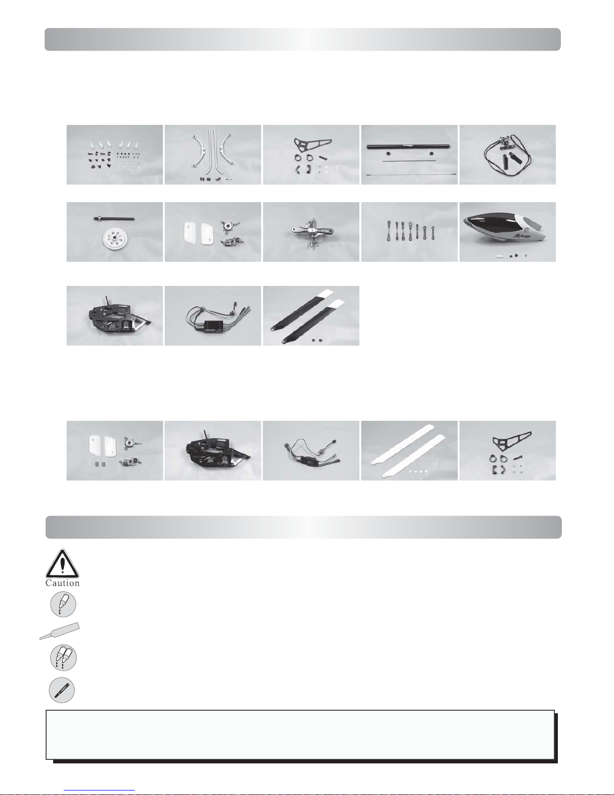
In The Box
This model is packed according to assembling steps. Do not open all the bags at one time.
Open only one bag for each step of assemply when building.
Atom 500
Use AB Glue
A
B
Use Blue Threadlock
Use Grease
Failure to follow these instructions may result in damage, personal injury or danger.
Symbols & assembling
* Always apply blue Threadlock when fixing Bolts on Metal parts.
* Always apply green retainer where bearings have to be fit into metal parts.
* Do not over-tighten self tapping screws into plastic parts or you will strip the threads!
G
Use Bearing Retainer
Atom 500R Differences
Step 1 Step 2 Step 3
Long Items
Tail Assembly
Step 4 Step 5
Rotor Head Assembly
Step 7 Step 10
Carbon Frame Set 60A ESC
Compass Carbon Blades
G10 Frame Set 40A ESC
Compass FG Blades
Step 3
Step 5 (With Flybar Weight)
Page 5
0
10
20
30
40
1
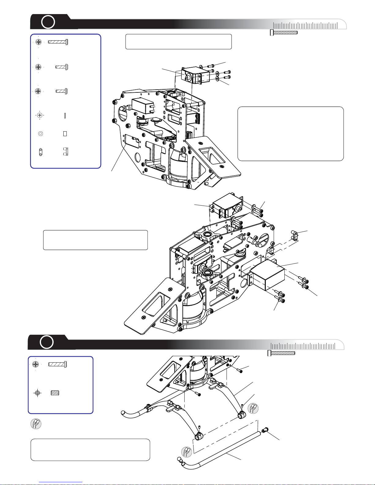
Servo
Servo Nut
M2.5x16 Self
Tapping Bolt
2.5mm Washer
Standard Size
Rudder Servo
M2.5x16 Self Tapping
Bolt X 4
2.5mm Washer X 16
M2.5x8 Self-Tapping Bolt
Mini Servo
2.5mm Washer
Hole for
Mini Rudder Servo
Plastic Spacer
M2.5x10 Self Tapping Bolt
M2.5x8 Self Tapping
Bolt X 8
M2.5x10 Self Tapping
Bolt X 4
Plastic Spacer x 4
Serv o Nu t x 2
0
10
20
30
40
Use AB Glue
M3x10 Self Tapping Bolt
M3x5 Set Screw
2
Landing Gear
Landing Gear Struts
Skid Cap
Landing Gear Skid
A
B
M3 x10 Self Tapping
Bolt X 4
M3x5 S et S crew X 4
A
B
A
B
The 4 Plastic Spacers are used to
bring the Elevator Servo Arm in
Line with the Swashplate Link Ball.
Tip: Do not over tighten the four 3 x 5mm
set screws as it can damage the landing
struts.
The Servo installation is done without
the supplied Servo Rubbers.
The Swashplate Servos are installed
in between the 2 frames. The Self
Tapping Bolts are screwed from the
inside, while the Self Tapping Bolts
for the Rudder Servo are screwed
from the out side. The supplied Servo
Nuts are only used for the Rudder
Servo.
Page 6
0
10
20
30
40
3
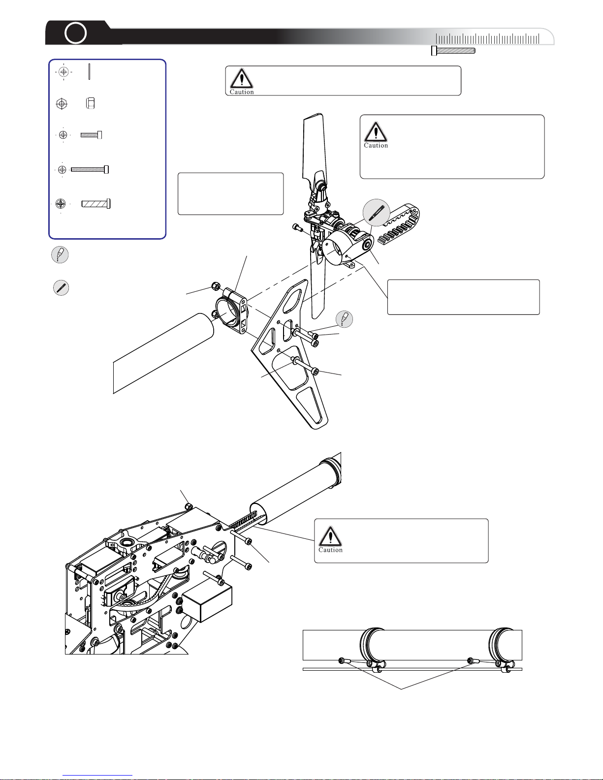
Boom & Tail Rotor
M3x40 Cap Head Bolt x4
Crimping Belt damages the Tensile Cords
and will result in premature failure.
M3 Washer x2
M3 Nylon Lock Nut x6
M2.5x6 Cap Head Bolt x2
Use Threadlock
M3x40 Cap
Head Bolt
M3 Nylon Nut
Slide theTail Boom through the
Tail Boom Mount. Twist theTail
Belt 90° to the right before
inserting it to the Idler Pulleys.
M2.5x8 Self Tapping Bolt
M2.5 x8 Self Tapping
Bolt X 2
Bearing Retainer
M3x25 Cap
Head Bolt
M3 Nylon
Nut
Vertical Fin Mount
M3 Washer
M2.5x6 Cap
Head Bolt
Insert theTail Boom
fully into the Tail Gear
Case before tightening
the 2.5x6mm Bolts.
Be careful not to over tighten the
Bolts when attaching theTail Rotor
Blades.The Tail Blades should be
able to move with a slight amount
of resistance within theTail Blade
Holders.
Tail Set
These Bolts are only used to
compress the boom, please do
not screw them the whole way in.
See Page Team Tips!
Page 7
0
10
20
30
40
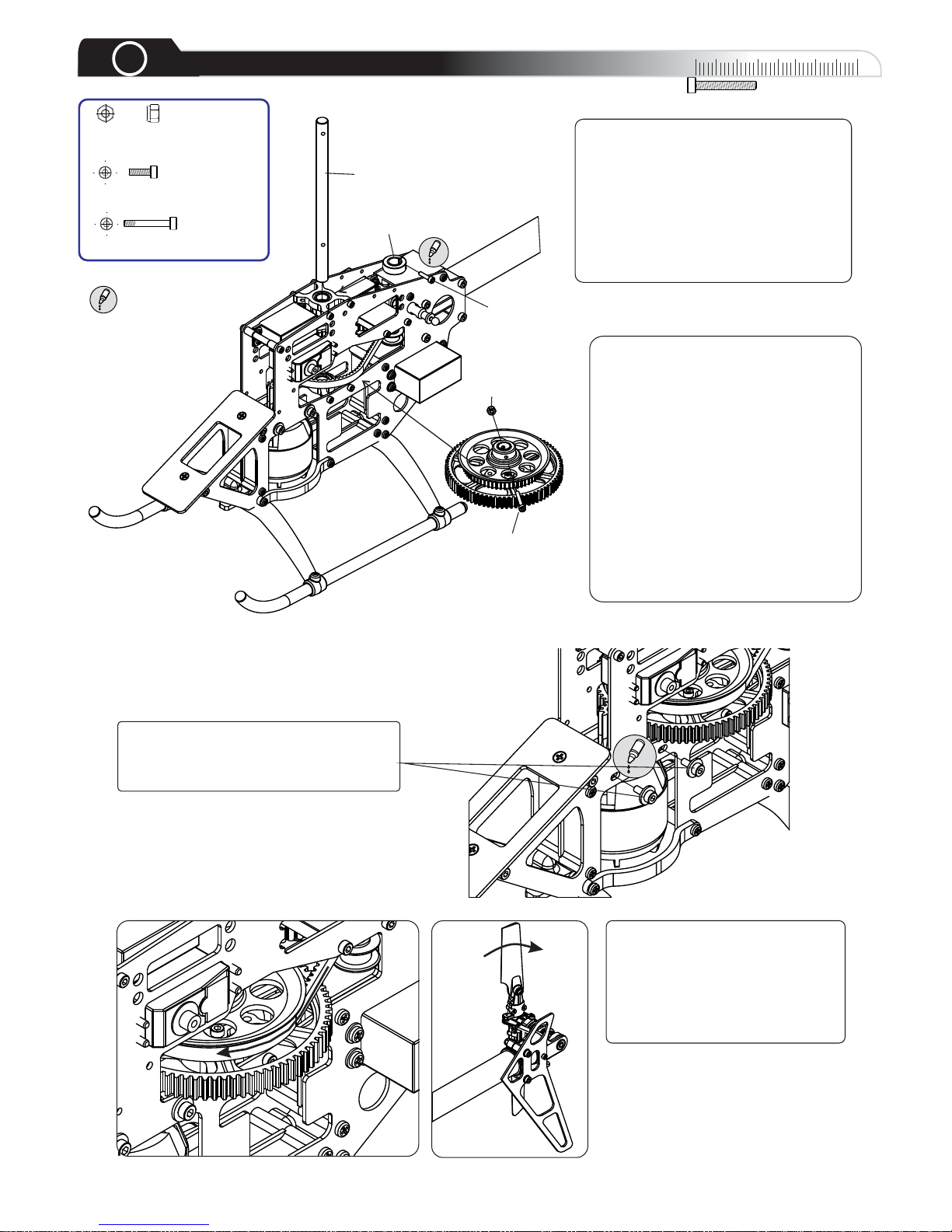
Main Gear
4
To adjust the correct backlash between
the Motor Pinion and the Main Gear
loose the 4 Motor Mount Bolts, then fix
them tightly with Threadlock.
M2.5x18 Shanked
Bolt
Main Shaft
M2.5x10 Cap
Head Bolt
Mast Collar
2.5mm Nylon
Lock Nut
M2.5 Nylon Lock Nut x1
M2.5x10 Cap Head Bolt x1
M2.5x18 Shanked Bolt x1
Use Threadlock
Gear BacklashAdjustment:
For smooth operation and
performance, it is necessary to adjust
the Gear Backlash properly. Excess
Gear Backlash can cause premature
Gear Wear and damage. Insufficient
Gear Backlash can cause vibration,
as well as overheating of the Motor
and Speed Controller.Adjust the Gear
Backlash by placing one piece of
paper between the Gears to set the
distance. When the Bolts are secure,
remove the paper andtest the Gear
Backlash to insure that there is a
slight amount of free movement
between the gears.
Check the correct rotation of the
Tail Rotor Blades. The Blade on
the Top moves to the rear. If the
Tail Rotor rotates incorrectly,
simply pull out the main shaft and
twist the Belt in the other
direction.
Lift the Main Shaft Collar upwards and
secure to the Main Shaft by slightly
tighten the Lock Screw. It is necessary
to align the Lock Screw through the
hole in the side of the Main Frame.
While securing the Lock Screw, make
sure that you are pushing down on the
Main Shaft so that there will be no
up/down play in the Main Shaft once
the collar is secured.
See Page Team Tips!
Page 8
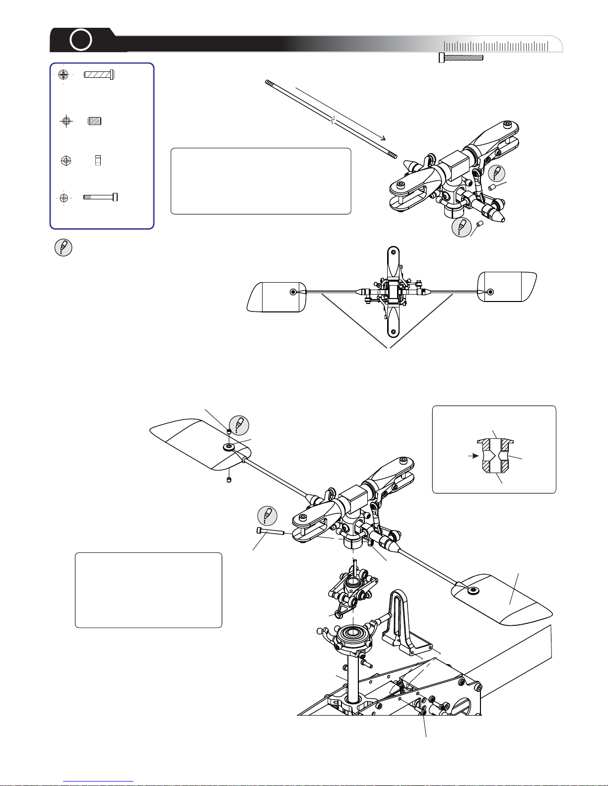
Adjust so that each side has exactly the same length
M2.5x16 Shanked
Bolt x1
Use Threadlock
M2.5 x8 Self Tapping
Bolt X 4
M3x3 Set Screw x8
2.5mm Nut x1
Paddle
Main Shaft
M3x3 Set Screw
M2.5x16
Shanked Bolt
2.5mm Nut
M2.5 x8 Self Tapping Bolt
Paddle Insert
Washout Link
Thread
Flybar
Thread
Thread
Paddle Insert
0
10
20
30
40
5
Rotor,Washout & Swashplate
P
u
s
h
t
h
e
F
l
y
b
a
r
i
n
Be sure to note the correct
direction of the Flybar Paddles
as shown in the diagram. It is
very important to insure that the
Paddles are in parallel to each
other, as well as to the Flybar
ControlArm Assembly.
In this step, push the Flybar trough the
Flybar Collar, Flybar Holder and the
Flybar ControlArms using the 3x3mm
set screws to fix theArms and Collars
onto the Flybar, care that both sides of
the Flybar are of equal length.
M3x3 Set Screw
M3x3
Set Screw
See Page Team Tips!
See Page Team Tips!
Page 9
0
10
20
30
40
6
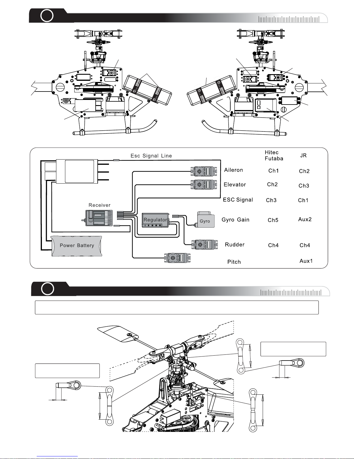
Equipment illustration
Esc
Velcro Tape
Pitch
Receiver
6S Battery
Aileron
Elevator
Rudder
ESC
00
10
20
30
40
00
7
Linkage
19mmx2
26mmx2
29mm
4.5mm
4.5mm
BEC power line
Ch6
To Motor
Please cut away 4.5mm
from each Ball Link.
Please cut away 4.5mm
from each Ball Link.
The following Linkage lengths indications are basic values. PLEASE BEAWARE THATTHEY COULD VARY
depend on used Servos andArms. Some fine adjustments are still needed in following setup steps.
Page 10
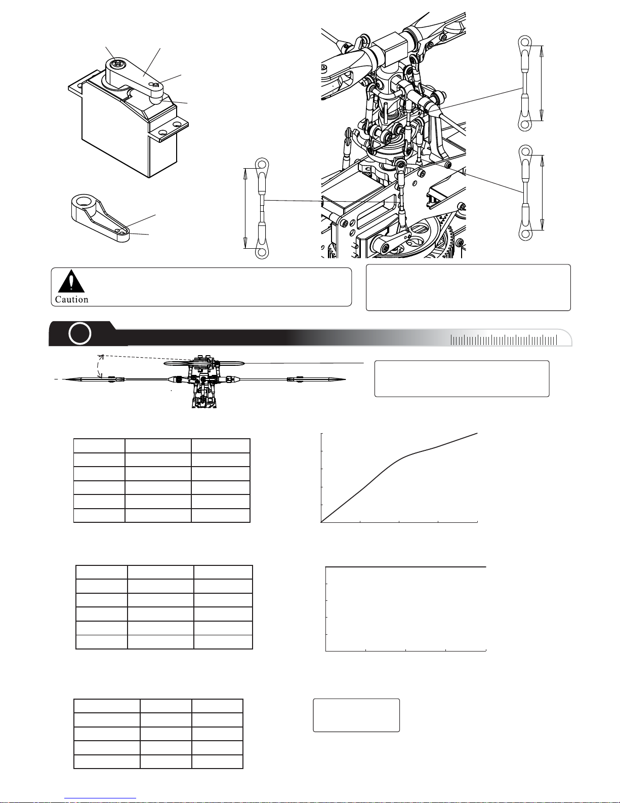
Servo Arm
Servo Screw
For Sport Flying
For 3D Flying
39.5mmx2
40.5mm
45.5mm
2x6mm Cap Head
Bolt
Stainless Balls
Do not apply plier to resize Ball Links. Pliers could
cause hidden damage to Ball Links and result in
failure when operation.
00
10
20
30
40
00
8
Setup
Pitch
General Flight
Throttle Pitch
5
100%
13 deg
4
85%
3
70%
4~5 deg
2
35%
1
0%
-4 deg
3D Style
Throttle Pitch
5
100%
13 deg
4
100%
6.5 deg
3
100%
0 deg
2
100%
-6.5 deg
1
100%
-13 deg
0%
20%
40%
60%
80%
100%
12345
0%
20%
40%
60%
80%
100%
12345
Throttle Curve
Throttle Curve
JR Futaba
Swash Type SWH
S3 120 SR3
Aile Elev Pitch
45% 50% 45%
Swash Type Setting
Timing: 22.5 deg
No Brakes
Very Soft Start
Esc Setup
Compass Model Ball Links are build up on
the tight side this allows you to adjust them
to your personal needs. For this we suggest
to use a Ball Link sizing tool.
The Atom 500 total pitch range is
about 26°. If you set the pitch too high
than flight time will be shortened.
Page 11
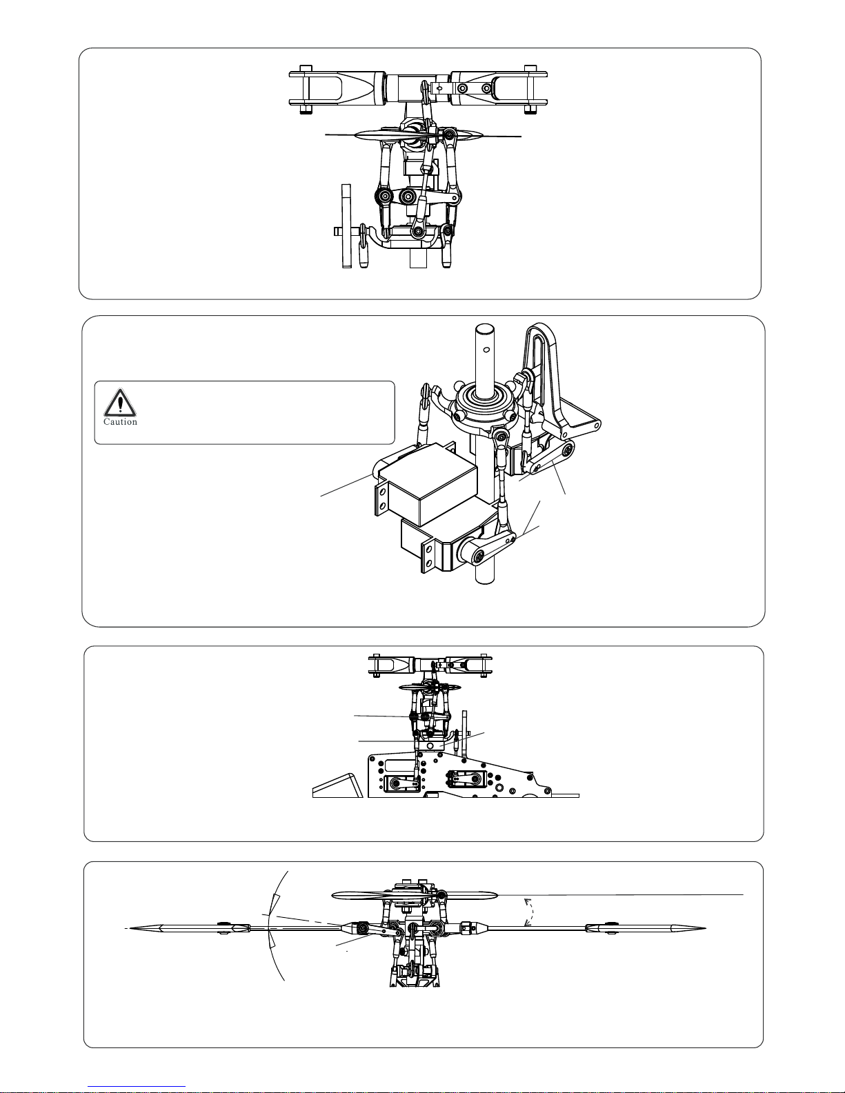
Parallel
Make sure that the Flybar ControlArms and Paddles are in line as shown in the diagram.
Horizontal
Horizontal
Attention:
WashoutArm
Horizontal
06 0501Swashplate Tool-
Swashplate
Horizontal
0 Pitch°
MixingArm
5
°
A
Turn on theTransmitter, set the Throttle Stick into center position for 0 ° Pitch. Use the Subtrim menu to
adjust the 3 Swash ServoArms to level.
B
To do all Basic Setups first UNPLUG
ESC from the receiver then use a 4.8V
Receiver Battery for the setup.
Level the Swashplate by adjusting the links from the ServoArms to the Swashplate. Use a
Compass SwashplateTool as guide.Then set level the Washout Arms.
C
By adjusting the Links between Swashplate and MixingArms set the MixingArms to a 5° downward position.
Adjust the Links between the MixingArms and the Main Blade Holder to set the Main Blade Pitch to 0°.
D
Page 12
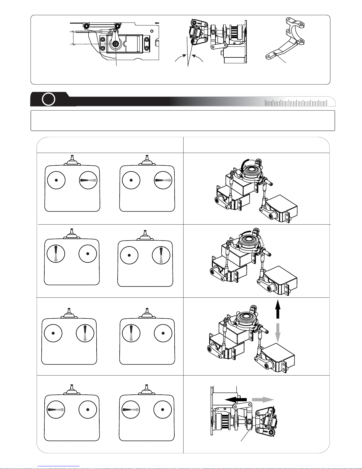
With Rudder Stick in middle position, set the Rudder Servo Arm at 90° to the Tail Control Link. Set the Tail
Blades to 7° Pitch.
90°
7°
Use this Hole for Tail Link Ball
Aileron Check
Mod 1
Mod 2
Swashplate Reaction
Tilt Left
Elevator Check
Tilt Forward
Tilt Right
Tilt
Backward
Rudder Check
Tail Pitch Plate
Slide left
Slide Right
Pitch Check
Swash Plate
Ascent
Descent
00
10
20
30
40
00
9
Servo Direction Check
Turn the Transmitter on, your position has to be right behind the helicopters Tail. Make sure that the Swashplate
Mode is set to CCPM 120°. Move the Sticks according to the drawings and check the reaction of the Swashplate
and the Tail Pitch Plate. Check as well your Throttle settings.Adjust your Transmitter settings accordingly.
13mm
E
Page 13
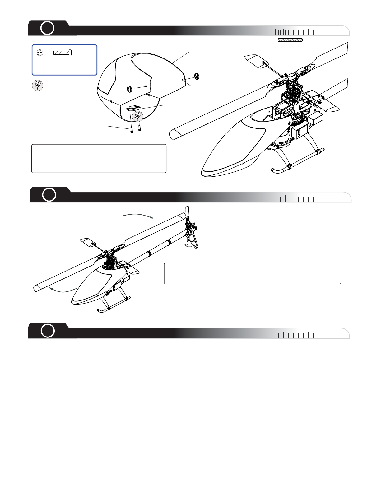
M2.5x6 Self
Tapping Bolt
Canopy
Canopy Insert
Use AB Glue
A
B
M2.5x6 Self Tapping
Bolt X 2
Drill a 6.5mm D
Hole here
A
B
ABA
B
00
10
20
30
40
00
10
Canopy
00
10
20
30
40
00
11
Rotor Direction
5. Check that main blades, paddles and tail blades are installed in the right direction.
6. Check that there are no missing or damaged parts, never fly with any damaged parts.
7. Make sure all electronic devices are firmly fastened and connected.
8. Before starting the motor, make sure the IDLE switch is OFF and throttle stick is in the low position.
9. Only turn off the transmitter after turning off the receiver.
1. Ensure that receiver & transmitter battery are fully charged.
2 Check all bolts and screws are tight..
3 Repeat step 9 to check all servo functions are correct..
4 Ensure tail and gyro direction are correctly set..
00
10
20
30
40
00
12
Pre Flight Check
Place the Canopy onto the Frames and mark
the right position of the Canopy Inserts. Apply
AB Glue to fix the Canopy Insert onto the
canopy.
When the Rotor spins clockwise the Tail Blades should turn
clockwise as well watching the Tail Rotor from the Tail Fin side.
If not Belt is installed the wrong way and has to be corrected.
Page 14
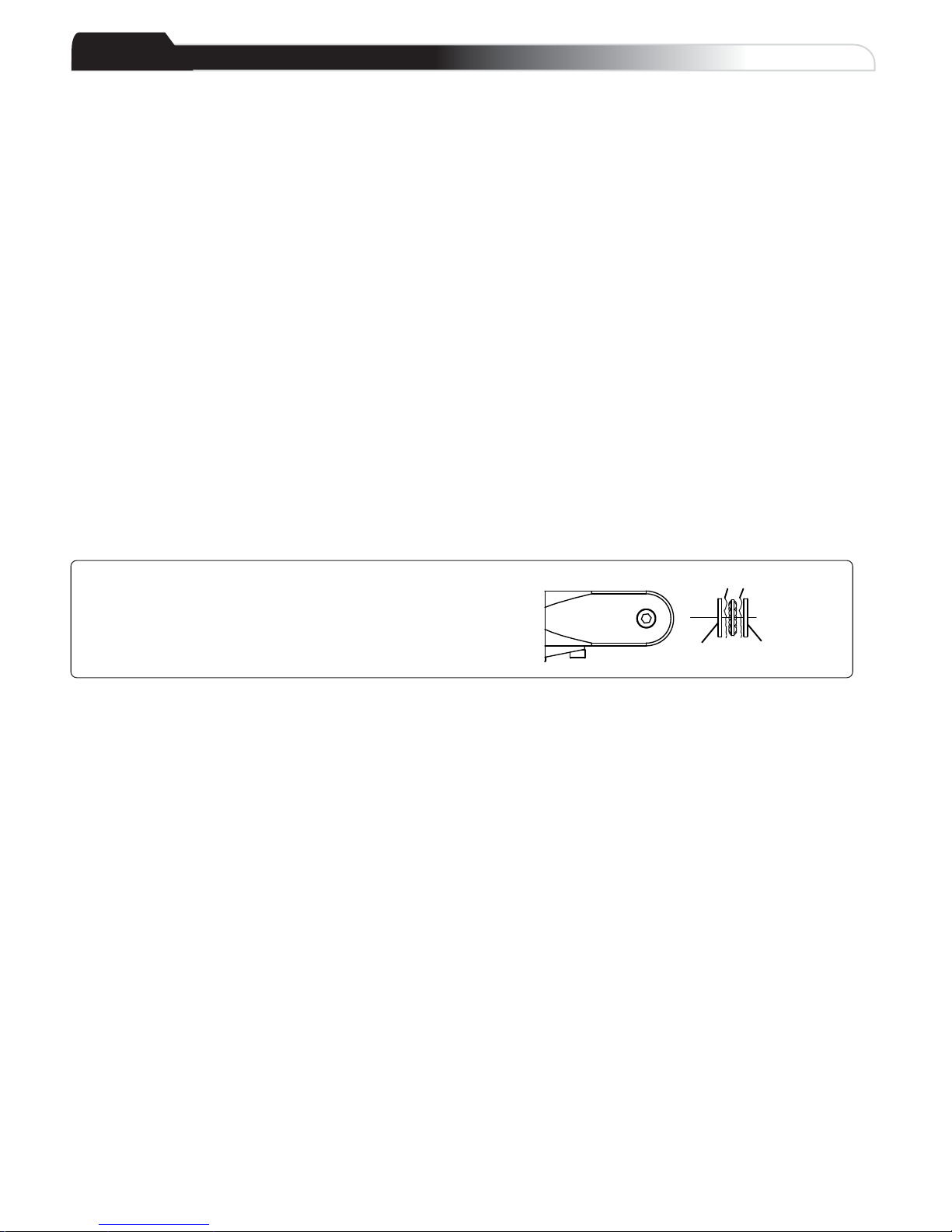
Main Grip
Apply Grease Here
Larger ID
(IN)
Smaller ID
(OUT)
Thrust Bearing Direction
Main grips are factory preassembled; in case of reassembling
make absolutely sure you use the correct “ID”ring at the correct
position. Placethe large IDTowards the Main Shaft and the
small I.D.Towards the Blades during assembly.
Team Tips
General:
Step 3
Step 4
Step 5
The Ball Links on theAtom need to be resized.These Ball Links will NOTbreak in over time. they
will stay tight and will cause unwanted interactions.
It is very important to resize the Ball Links for smooth travel, especially on the tail; because issues
like tail wag, sluggish tail, or inconsistent Piro-rate will occur.
It is vital not to over tighten the Main Gear Bolt, or it can cause theAutorotation Gear to slightly
warp.This can cause a premature Belt failure, or reduce the lifetime of the Belt.
:
To improve '3D'Tail Rotor authority we suggest doing the “Tail Blade Grip Flip”. The result is
a increased stability in 3D flying.
:
:
LeaveAbout 0.1mm space between the Flybar Collar and the Flybar Holder, this avoids the
Flybar to snap when flying.
Page 15

Parts List
Atom 500
Version 2.5/2009
How to order your parts!
1. Check part number on the drawing
2. Use the part number to find the ORDER number on the list
3. Only use ORDER number for your parts order
Copyright Compass Model 2009
As we continue to improve our products, this part list may not reflect all recent product amendmends.
For more information, please refer to www.compassmodel.com
Page 16
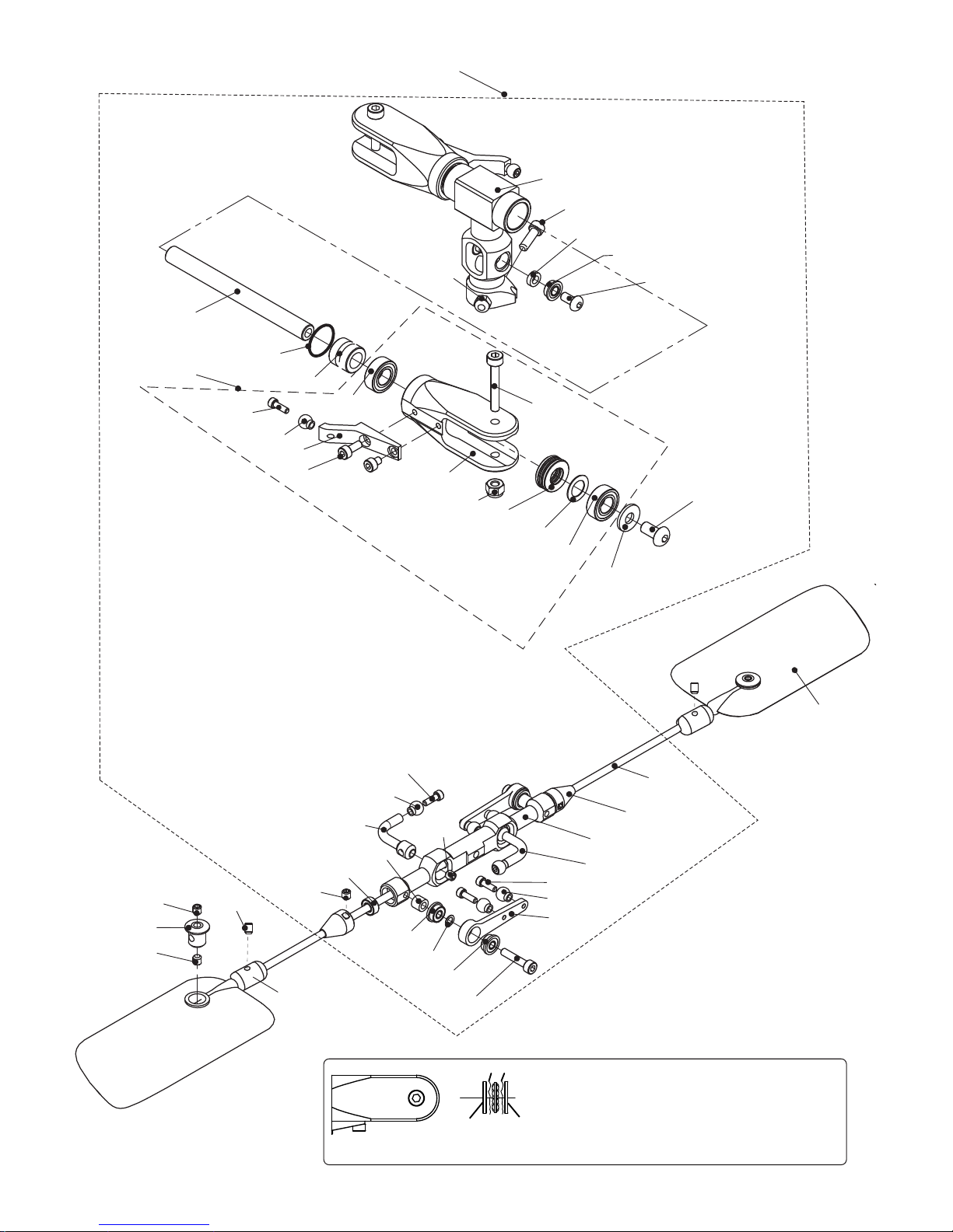
02-0701
80-0322S
06-0109
80-2516
06-0102
06-0106N
79-0306
82-621003
06-0114
91-0003
80-0206
60-6124
06-0108
80-2506
06-0101
63-61245
60-6124
82-4101
79-0408
91-0025
61-3062
97-0715
06-5101
06-8104
61-2562
81-0303
80-0206S
02-0701
06-0507
06-0513
06-0505
80-2512
06-0504
06-0512
81-0303
06-0510
06-0511
06-0507
02-0701
61-2562
82-2540
06-0508
60-2562
81-0304
06-0514
80-0206S
81-0303
81-0303
Main Grip
Apply Grease Here
Larger ID
(IN)
Smaller ID
(OUT)
Thrust Bearing Direction
Main grips are factory preassembled; in
case of reassembling make absolutely
sure you use the correct “ID” ring at the
correct position. Place the large ID
Towards the Main Shaft and the small I.D.
Towards the Blades during assembly.
Page 17

Part No. Part Description Order No. Order Description Remark
02-0701 Stainless Link Ball
02-0701
Stainless Link Balls 10 pcs/bag
06-0101 Main Blade Holder
06-5101
Main Blade Holder set (Atom 500) 1 set/bag
06-0102 Rotor Hub Washer
06-0106Z
Rotor Hub set (Atom 500) 1 set/bag
06-0106N Rotor Hub
06-0106Z
Rotor Hub set (Atom 500) 1 set/bag
06-0108 Main Blade Holder Arm
06-0108S
Main Blade Holder Arm set (Atom 500) 2 set/bag
06-0109 Delrin Dampner
06-0109
Delrin Dampner (Atom 500) 2 pcs/bag
06-0114 Spindle Shaft
06-0114
Spindle Shaft set (Atom 500) 3 pcs/bag
06-0504 Flybar Holder
06-0504
Flybar Holder w. Bearings (Atom 500) 1 set/bag
06-0505 Mixing Arm
06-0505Z
Mixing Arm set (Atom 500) 2 set/bag
06-0507 Flybar Control Arm
06-0507
Flybar Control Arm set (Atom 500) 2 pcs/bag
06-0508 Mixing Arm Collar
06-0505Z
Mixing Arm set (Atom 500) 2 pcs/bag
06-0510 Flybar
06-0510
Flybar set (Atom 500) 3 pcs/bag
06-0511 Flybar Collar
06-0511
Flybar Collar set (Atom 500) 1 set/bag
Paddle 11gr (default)
06-0512H
Paddle set 11g default (Atom 500) 1 set/bag
Paddle 7gr (3D)
06-0512L
Paddle 7gr 3D (Atom 500) 1 set/bag
06-0513 Paddle Insert
06-0512H
Paddle Insert set (Atom 500) 1 set/bag
06-0514 Flybar Weight (Atom 500R)
06-0514S
Flybar Weight set (Atom 500R) 1 set/bag
06-5101 Main Blade Holder complete
06-5101
Main Blade Holder complete set (Atom 500) 1 set/bag
06-8104 Rotor Complete
06-8104
Rotor set complete w. Flybarholder (Atom 500) 1 set/bag
60-2562 Ball Bearing 2.5x6x2.5
60-2562
Ball Bearings 2.5x6x2.5 2 pcs/bag
60-6124 Ball Bearing 6x12x4
60-6124
Ball Bearings 6x12x4 2 pcs/bag
61-2562 Flanged Bearing 2.5x6x2.6
61-2562
Flanged Bearings 2.5x6x2.6 4 set/bag
61-3062 Flanged Bearing 3x6x2
61-3062
Flanged Bearings 3x6x2 4 set/bag
63-61245 Thrust Bearing 6x12x4.5
63-61245
Thrust Bearings 6x12x4.5 2 pcs/bag
79-0306 Button Head Bolt M3x6
79-0306
Button Head Bolts M3x6 10 pcs/bag
79-0408 Button Head Bolt M4x8
79-0408
Button Head Bolts M4x8 10 pcs/bag
80-0206S Cap Head Bolt 2x6 (Link Balls)
80-0206S
Cap Head Bolts 2x6 (Link Balls) 10 pcs/bag
80-0322S Cap Head Bolt M3x22 (shanked)
80-0322s
Cap Head Bolts M3x22 (shanked) 2 pcs/bag
80-2506 Cap Head Bolt M2.5x6
80-2506
Cap Head Bolts M2.5x6 10 pcs/bag
80-2512 Cap Head Bolt M2.5x12
80-2512
Cap Head Bolts M2.5x12 10 pcs/bag
80-2516 Cap Head Bolt M2.5x16
80-2516
Cap Head Bolts M2.5x16 2 pcs/bag
81-0303 Set Screw M3x3
81-0303
Set Screws M3x3 10 pcs/bag
81-0304 Set Screw M3x4
81-0304
Set Screws M3x4 10 pcs/bag
82-2540 Washer 2.5x4.1x0.2
82-2540
Washers 2.5x4.1x0.2 10 pcs/bag
82-4101 Washer 4.1x10x1
82-4101
Washers 4.1x10x1 10 pcs/bag
82-621003 Washer 6.2x10x0.3 (spindle)
82-621003
Washers 6.2x10x0.3 (spindle) 10 pcs/bag
91-0003 Nylon Nut M3
91-0003
Nylon Nuts M3 10 pcs/bag
97-0715 Rubber O-Ring 10x7x1.5
97-0715
Rubber O-Ring set10x7x1.5 4 pcs/bag
06-0512
Page 18
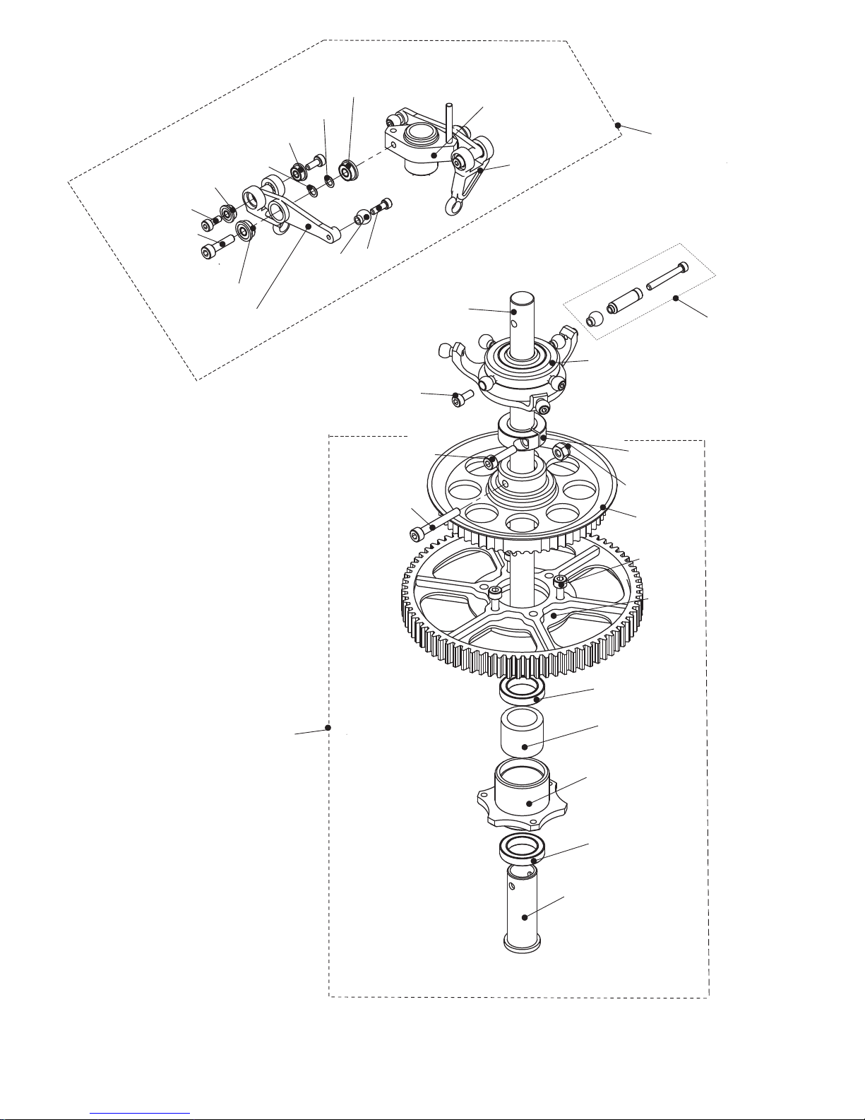
80-0206S
06-0503
06-0518
61-2562
80-0205
61-2052
82-2540
82-2540
80-2510
61-2562
06-0520
02-0701
61-2052
06 8502-
06-0607
06-8421
06-4502
80-2508
06-4603
60-10153
62-101412
06-0603
06-0605
06-0608
80-2518
80-2510
6 -1010 53
06 8602-
91 0025-
80 0206-
06 0410S-
Page 19

Part No. Part Description Order No. Order Description Remark
02-0701 Stainless Link Ball
02-0701
Stainless Link Balls 10 pcs/bag
06-0410S Swashplate Pin
06-0410S
Swashplate Pin Set (Atom 500) 1 set/bag
06-0503 Washout Base
06-0503S
Washout Base set (Atom 500) 1 set/bag
06-0518 Washout Link
06-0518
Washout Links (Atom 500) 2 pcs/bag
06-0520 Washout Control Arm
06-0520Z
Washout Control Arm set (Atom 500) 1 set/bag
06-0603 Autorotation Hub
06-0603Z
Autorotation Hub w. Bearing (Atom 500) 1 set/bag
06-0605 Autorotation Sleeve
06-0605
Autorotation Sleeve (Atom 500) 1 pcs/bag
06-0607 Main Shaft (Ø 8mm)
06-0607
Main Shaft (Atom 500 Ø 8mm) 1 pcs/bag
06-0608 Main Shaft Lock Clamp (Ø 8mm)
06-0608S
Main Shaft Lock Clamp set (Atom 500 Ø 8mm) 1 set/bag
06-4502 Main Pulley
06-4502
Main Pulley (Atom 500) 1 pcs/bag
06-4603 Main Gear
06-4603
Main Gear (Atom 500) 1 pcs/bag
06-8421 Swashplate
06-8421
Swashplate complete (Atom 500) 1 set/bag
06-8502 Washout complete
06-8502
Washout set complete (Atom 500) 1 set/bag
06-8602 Main Gear w. Pulley Assembly
06-8602
Main Gear w. Pulley Assembly (Atom 500) 1 set/bag
60-10153 Ball Bearing 10x15x3
60-10153
Ball Bearings 10x15x3 2 pcs/bag
61-2052 Flanged Bearing 2x5x2.5
61-2052
Flanged Bearings 2x5x2.5 4 pcs/bag
61-2562 Flanged Bearing 2.5x6x2.6
61-2562
Flanged Bearings 2.5x6x2.6 4 pcs/bag
62-101412 One Way Bearing 10x14x12
62-101412
One Way Bearing 10x14x12 1 set/bag
80-0205 Cap Head Bolt M2x5
80-0205
Cap Head Bolts M2x5 10 pcs/bag
80-0206S Cap Head Bolt 2x6 (Link Balls)
80-0206S
Cap Head Bolts 2x6 (Link Balls) 10 pcs/bag
80-2508 Cap Head Bolt M2.5x8
80-2508
Cap Head Bolts M2.5x8 10 pcs/bag
80-2510 Cap Head Bolt M2.5x10
80-2510
Cap Head Bolts M2.5x10 10 pcs/bag
80-2518 Cap Head Bolt M2.5x18
80-2518
Cap Head Bolts M2.5x18 2 pcs/bag
82-2540 Washer 2.5x4.1x0.2
82-2540
Washers 2.5x4.1x0.2 10 pcs/bag
91-0025 Nylon Nut M2.5
91-0025
Nylon Nuts M2.5 10 pcs/bag
Page 20
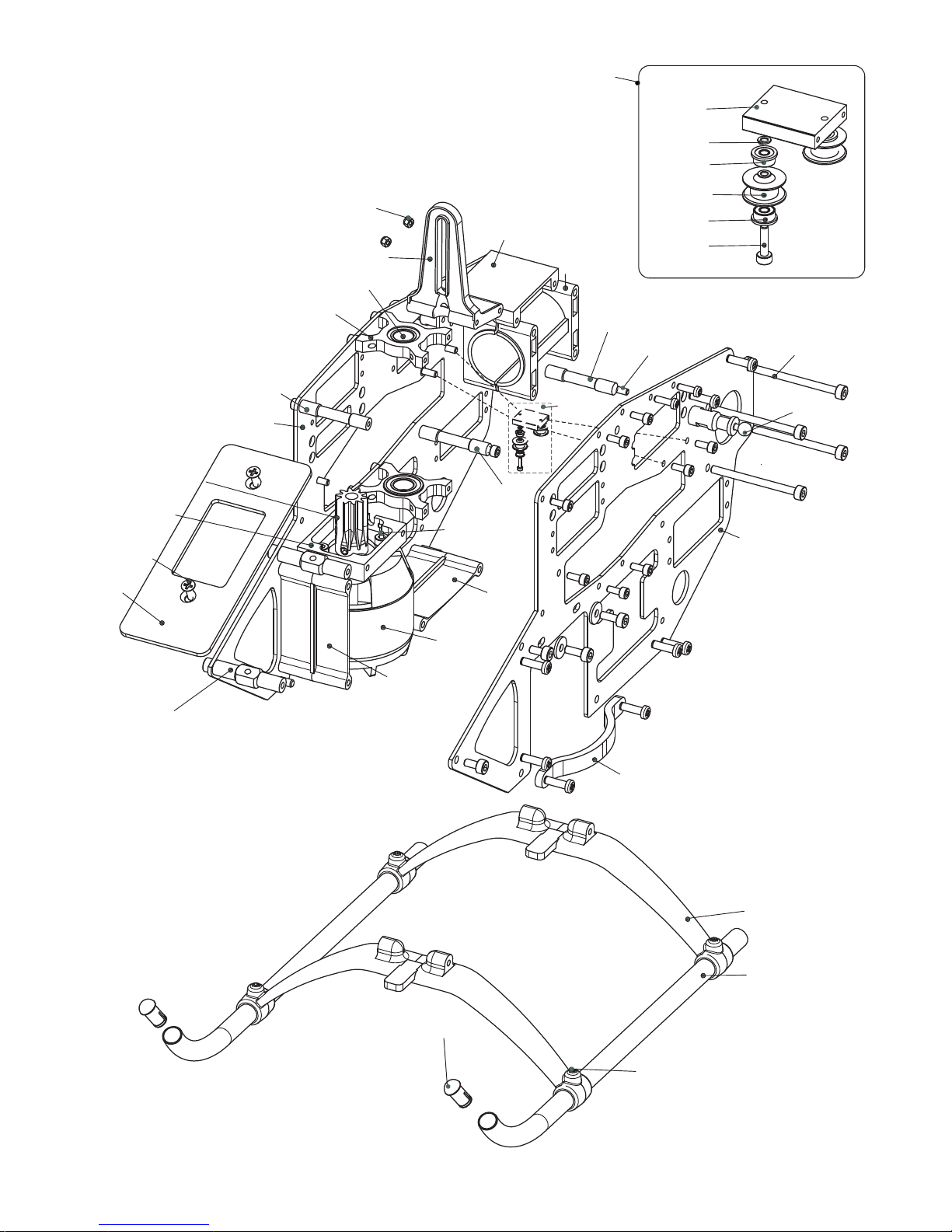
C5016
78 0308-
06 0830R-
06 0822-
06 0606-
06 0905-
06 0843-
02 825-1
02 0845-
02 0849-
06 0302-
02 1805-
06 0811-
06 4309-
60 8165-
(- )06 4308
(- )06 4310
80 0306-
02 0805-
07 0818-
80 0314-
61 3084-
06 0828-
61 3084-
82 3- 504
06-8203
81 0316-
06 0822-
06 8203
-
06 0305-
06 0830L-
80 0340-
06 0812-
80 2506-
95 2508-
95 0310-
80 0308-
82 3201-
a
a
a
a
a
a
a
a
a:
b
b
b:
c:
c
c
d:
d
d
e:
e
e
e
e
e
e
e
e
f:
80 0306-
f
f
9 00031-
06 0827-
06 0818-
81 0305-
02 0820-
Page 21

Part No. Part Description Order No. Order Description Remark
02-0805 Cross Member
02-0805
Cross Member set 5 pcs/bag
02-0820 Skid End Caps
02-0820
Skid End Caps 4 pcs/bag
02-0845 Frame Member
02-0849S
Frame Member set 2 pcs/bag
02-0849 Frame Member
02-0849S
Frame Member set 2 pcs/bag
02-1805 Cross Member
02-1805
Cross Member set 2 pcs/bag
02-1825 Tail Boom Mount
02-1825S
Tail Boom Mount w, Bolts 1 set/bag
06-0302 Motor Mount
06-0302S
Motor Mount w. Bolts 1 set/bag
06-0305 Frame Connector(Plastic)
06-0305
Frame Connectors Plastic w. Bolts 2 pcs/bag
06-0606 Bearing Block
06-0606Z
Bearing Block w. Bearing (Atom 500) 1 pcs/bag
06-0811 Battery Tray
06-0811S
Battery Tray w, Bolts (Atom 500) 1 pcs/bag
06-0812 Canopy Standoff
06-0812
Canopy Standoff set (Atom 500) 2 pcs/bag
06-0818 Landing Gear Skid
06-0818S
Landing Gear Skids w. Caps (Atom 500) 2 pcs/bag
06-0822 Cross Member
06-0822
Cross Member set (Atom 500) 2 pcs/bag
06-0827 Landing Gear Strut
06-0827
Landing Gear Struts (Atom 500) 2 pcs/bag
06-0828 Guide Pulley
06-0828Z
Guide Pulley set (Atom 500) 2 set/bag
06-0830L Main Frame Left Atom R (G10)
06-0830L
Main Frame Left Atom R (G10) 1 pcs/bag
06-0830LT Main Frame Left (Carbon)
06-0830LT
Main Frame Left (Carbon) 1 pcs/bag
06-0830R Main Frame Right Atom R (G10)
06-0830R
Main Frame Right Atom R (G10) 1 pcs/bag
06-0830RT Main Frame Right (Carbon)
06-0830RT
Main Frame Right (Carbon) 1 pcs/bag
06-0843 Gyro Mount
06-0843
Gyro Mount 1 pcs/bag
06-0905 Swashplate Guide
06-0905
Swashplate Guide (Atom 500) 1 pcs/bag
06-4308 Pinion Gear 8T (Atom R)
06-4308
Pinion Gear 8T (Atom R) 1 set/bag
06-4309 Pinion Gear 9T (default)
06-4309
Pinion Gear 9T (default) 1 set/bag
06-4310 Pinion Gear 10T (3D extreme)
06-4310
Pinion Gear 10T (3D extreme) 1 set/bag
06-8203 Guide Pulley set
06-8203
Guide Pulley set (Atom 500) 1 set/bag
07-0818 Guide Pulley Mount
07-0818
Guide Pulley Mount set 1 set/bag
60-8165 Ball Bearing 8x16x5
60-8165
Ball Bearings 8x16x5 2 pcs/bag
61-3084 Flanged Bearing 3x8x4
61-3084
Flanged Bearings 3x8x4 2 pcs/bag
78-0308 Flat Head Bolt M4x8
78-0308
Flat Head Bolts M4x8 10 pcs/bag
80-0306 Cap Head Bolt M3x6
80-0306
Cap Head Bolts M3x6 10 pcs/bag
80-0308 Cap Head Bolt M3x8
80-0308
Cap Head Bolts M3x8 10 pcs/bag
80-0314 Cap Head Bolt M3x14
80-0314
Cap Head Bolts M3x14 10 pcs/bag
80-0340 Cap Head Bolt M3x40
80-0335
Cap Head Bolts M3x40 10 pcs/bag
80-2506 Cap Head Bolt M2.5x6
80-2506
Cap Head Bolts M2.5x6 10 pcs/bag
81-0305 Set Screw M3x5
81-0305
Set Screws M3x5 10 pcs/bag
81-0316 Set Screw M3x16
81-0316
Set Screws M3x16 10 pcs/bag
82-3201 Washer 3.2x10x1.2
82-3201
Washers 3.2x10x1.2 10 pcs/bag
82-3504 Washer 3.2x5.2x0.4
82-3504
Washers 3.2x5.2x0.4 10 pcs/bag
91-0003 Nylon Nut M3
91-0003
Nylon Nuts M3 10 pcs/bag
95-0310 Self Tapping Screw M3x10
95-0310
Self Tapping Screws M3x10 10 pcs/bag
95-2508 Self Tapping Screw M2.5x8
95-2508
Self Tapping Screws M2.5x8 10 pcs/bag
C5016 BL Motor for Atom 500 6S
C-5016
BL Motor for Atom 500 6S 1 set/bag
Page 22
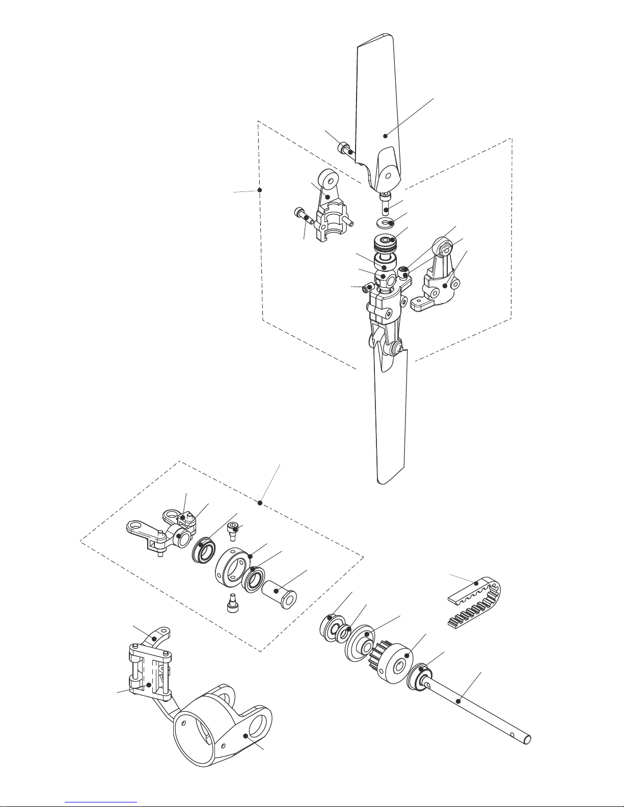
80 2508-
80 2512-
06 0210A-
80 0208-
82 2507-
06 0216-
63 4094-
60 4094-
06 0209-
81 0305-
06 0210B-
02 0701-
80 0206s-
06-5210
06 0212-
06 0214-
06 0208-
06 0205-
06 0204-
06 0206-
61 6103-
06 0222-
61 6103-
06 0207-
61 4104-
82 4264-
06 4205-
06 4204-
61 4104-
06 0213-
06-5206
98 1263-
Page 23

Part No. Part Description Order No. Order Description Remark
02-0701 Stainless Link Ball
02-0701
Stainless Link Balls 10 pcs/bag
06-0204 Tail Pitch Plate
06-0204S
Tail Pitch Plate w. Pin (Atom 500) 1 set/bag
06-0205 Tail Blade Link
06-0205S
Tail Blade Links w, Pin (Atom 500) 2 set/bag
06-0206 Tail Pitch Slider
06-0206Z
Tail Pitch Slider w. BB (Atom 500) 1 set/bag
06-0207 Tail Slider Ring
06-0207
Tail Slider Ring (Atom 500) 1 pcs/bag
06-0208 Tail Pitch Lever (crank)
06-0213S
Tail Pitch Lever set (Atom 500) 1 set/bag
06-0209 Tail Rotor Hub
06-0209
Tail Rotor Hub (Atom 500) 1 pcs/bag
06-0210AB Tail Blade Holder
06-0210AB
Tail Blade Holder (Atom 500) 2 pcs/bag
06-0212 Tail Gear Box
06-0212Z
Tail Gear Box 1 set/bag
06-0213 Tail Pitch Lever (H)
06-0213S
Tail Pitch Lever set (Atom 500) 1 set/bag
06-0214 Tail Shaft
06-0214
Tail Shaft set (Atom 500) 2 pcs/bag
06-0216 Tail Blade
06-0216
Tail Blade set 2 pcs/bag
06-0222 Guide Pin Bolt
06-0222
Guide Pin Bolts 2 pcs/bag
06-4204 Tail Pulley
06-4204S
Tail Pulley set (Atom 500) 1 set/bag
06-4205 Tail Pulley Cover
06-4204S
Tail Pulley set (Atom 500) 1 set/bag
06-5206 Tail Control set complete
06-5206
Tail Control set complete (Atom 500) 1 set/bag
06-5210 Tail Rotor set complete
06-5210
Tail Rotor set complete (Atom 500) 1 set/bag
60-4094 Ball Bearing 4x9x4
60-4094
Ball Bearings 4x9x4 5 pcs/bag
61-4104 Flanged Bearing 4x10x4
61-4104
Flanged Bearings 4x10x4 2 pcs/bag
61-6103 Flanged Bearing 6x10x3
61-6103
Flanged Bearings 6x10x3 2 pcs/bag
63-4094 Thrust Bearing 4x9x4
63-4094
Thrust Bearings 4x9x4 2 pcs/bag
80-0206S Cap Head Bolt 2x6 (Link Balls)
80-0206S
Cap Head Bolts 2x6 (Link Balls) 10 pcs/bag
80-0208 Cap Head Bolt M2x8
80-0208
Cap Head Bolts M2x8 10 pcs/bag
80-2508 Cap Head Bolt M2.5x8
80-2508
Cap Head Bolts M2.5x8 10 pcs/bag
80-2512 Cap Head Bolt M2.5x12
80-2512
Cap Head Bolts M2.5x12 10 pcs/bag
81-0305 Set Screw M3x5
81-0305
Set Screws M3x5 10 pcs/bag
82-2507 Washer 2.7x8x0.8
82-2507
Washers 2.7x8x0.8 10 pcs/bag
82-4264 Washer 4.2x6.4x.026
82-4264
Washers 4.2x6.4x.026 10 pcs/bag
98-1263 Belt (Atom 500)
98-1263
Belt (Atom 500) 1 pcs/bag
Page 24
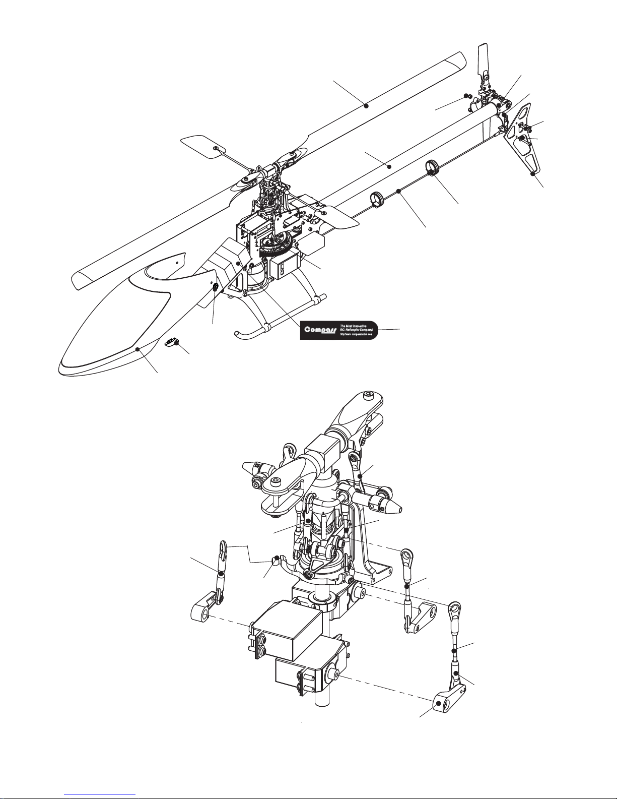
06-0826
06-0852
06-0817
06-8202
80-0325
02-0818
420- 455
06-0823AB
02 0853-
06 0707FU-
06 0851-
VBT270
(06 0707JR)-
F 06 0430--
(F 06 0430T)--
02 0701-
40 2010-
02 0709-
40 2015-
40 2010-
40 2030-
40 2025-
40 2025-
8 -32201
91 003-0
Linkages
06 0707FU-
(06 0707JR)-
Page 25

Part No. Part Description Order No. Order Description Remark
02-0709 Ball Links
02-0709
Ball Links 10 pcs/bag
02-0818 Tail Linkrod Guide
02-0818S
Tail Linkrod Guide set 4 pcs/bag
02-0853 Canopy Dampner
02-0853
Canopy Dampner 4 set/bag
06-0817 Tail Fin G10
06-0817
Tail Fin G10 1 pcs/bag
06-0817T Tail Fin Carbon
06-0817T
Tail Fin Carbon 1 pcs/bag
06-0823AB Vertical Fin Clamp
06-0823AB
Vertical Fin Clamp 1 set/bag
06-0826 Tail Boom
06-0826
Tail Booms (Atom 500) 2 pcs/bag
06-0851 Canopy Insert
06-0851
Canopy Inserts 1 set/bag
Painted FG Canopy (Atom yellow)
06-0852S
Painted FG Canopy (Atom yellow) 1 set/bag
FG Canopy White (Atom)
06-0852W
FG Canopy White (Atom) 1 set/bag
06-8202 Tail Gear Box set
06-8202
Tail Gear Box set Complete (Atom 500) 1 set/bag
06-0707FU Servo Arm (FUTABA)
06-0707FU
Servo Arm set (FUTABA) 1 set/bag
06-0707JR Servo Arm (JR)
06-0707JR
Servo Arm set (JR) 1 set/bag
40-2455 Tail Link Rod
40-2455
Tail Link Rod 1 pcs/bag
40-2010 Link Rod 10mm
E-LG-04
Link Rod set (Atom 500) 1 set/bag
40-2015 Link Rod 15mm
E-LG-04
Link Rod set (Atom 500) 1 set/bag
40-2025 Link Rod 25mm
E-LG-04
Link Rod set (Atom 500) 1 set/bag
40-2030 Link Rod 30mm
E-LG-04
Link Rod set (Atom 500) 1 set/bag
80-0325 Cap Head Screw M3x25
80-0325
Cap Head Screws M3x25 10 pcs/bag
82-3201 Washer 3.2x10x1.2
82-3201
Washers 3.2x10x1.2 10 pcs/bag
91-0003 Nylon Nut M3
91-0003
Nylon Nuts M3 10 pcs/bag
VBT270 Velcro Binding Tape 270x20
VBT270
Velcro Binding Tape 270x20 4 pcs/bag
F-06-0430 Compass FG Blade 430mm
F-06-0430
Compass FG Blade set 430mm 1 pair/bag
F-06-0430T Compass Carbon Blade 430mm
F-06-0430T
Compass Carbon Blade set 430mm 1 pair/bag
06-0852
Special Thanks To:
John Lancaster
Dirk Everaert
Jelte De Vries
David Ketelhut
Devin LeBlanc
Jenkins Cortez
Jonas Schelpe
Brian Tran
Page 26

COMPASS MODEL (HK) LIMITED
www.compassmodel.com
 Loading...