

Page 1
Page 2

Page 3

Introduction
Congratulations on your purchase of the Compass Model Atom 7HV Electric Powered Helicopter. This model has been
designed using the latest in state-of-the-art design technology. To achieve the best performance and reliability from this
model, please read through these instructions carefully so you become familiar with the contents of this kit before assembly.
AMA Information
We strongly encourage all prospective and current R/C aircraft pilots to join the Academy of Model Aeronautics. TheAMAis
a non-profit organization that provides services to model aircraft pilots. As an AMA member, you will receive a monthly
magazine entitled Model Aviation, as well as liability insurance plan to cover against possible accident or injury. All AMA
charter aircraft clubs require individuals to hold a current AMA sporting license prior to operation of their models. For
further information, you can contact the AMA at:
Academy of Model Aeronautics
5151 East Memorial Drive
Muncie, IN47302
Warning
The radio-controlled model helicopter contained in this kit is not a toy, but a sophisticated piece of equipment. This product
is not recommended for use by children. Radio-controlled models such as this are capable of causing both property damage
and/or bodily harm to both the operator/assembler and/or spectator if not properly assembled and operated. Compass
Model Ltd. assumes no liability for damage that could occur from the assembly and/or use/misuse of this product.Although
the Atom 7HV is powered by a quiet, smooth-running electric motor, it should be assembled and operated with the same
care as glow engine helicopters. When operating your Atom 7HV, please exercise caution and safety.
Warranty
The warranty covers defects in material or workmanship or missing components to the original purchaser for 30 days from
the date of purchase. Compass Model Ltd. will replace or repair, at our discretion, the defective or missing component.
Defective components must be returned to our Distributor prior to replacement.
Any part, which has been improperly installed, abused, crash damaged or altered by unauthorized agencies is not covered.
Under no circumstances will the buyer be entitled to consequential or incidental damages. The components used in this kit
are made from special materials designed for special applications and design strengths. We recommend that all replacement
parts be original parts manufactured by Compass Model Ltd. to ensure proper and safe operation of your model. Any part
used which was manufactured by any firm other than Compass Model Ltd. VOIDS all warranties of this product by Compass
Model Ltd.
Warranty Procedures
Mail all warranty information within 15 days of original purchase date. If service is required, send the component in
question (if not missing) together with a photocopy of your bill of sale and an accurate description of the problem and part.
Ship components fully insured and prepaid. Compass Model Ltd. is not responsible for any shipping damages. We will, at
our discretion, notify you of any costs involved, or ship it COD. You are required to pay all postage, shipping and insurance
charges.
R/C Helicopter Safety
A model helicopter must be built exactly in accordance with the assembly instructions. Compass Model Ltd. has spent much
time and efforts refining this product to make it reliable in operation and easy to build. Vibration and stress levels are high and
all fasteners and attachments must be secure for safe operation. Safe operation is the responsibility of the builder/flyer and
starts with careful construction and continues with selection and installation of reliable radio equipment and motor/engine.
The need for safety is nowhere greater than at the flying field. A number of guidelines for safe flight have been developed by
experienced flyers and are set down here. It is urged that they be read, understood and followed.
Attention:
rules to apply in your country/Flying field.
each country has its own security application which cannot be laid down here so prior to any flight request the
Atom 7HV LimitationsAttention :
Atom 7HV Max. rotor head rpm: 2100 U/min
Atom 7HV Max. collective pitch range: +/- 12°
Page 4
Guidelines for Safe R/C Helicopter Flight
• Fly only at approved flying fields and obey field regulations.
• Follow frequency control procedures. Interference can be dangerous to all.
• Obtain assistance from experienced pilots.
• The Guidance provided by experienced pilots is valuable and sometimes necessary.
• Know your radio. Check all transmitter functions before each flight.
• Be aware that rotating blades are very dangerous and can cause serious injury or even death.
• Never fly near or above spectators other modelers or animals.
• Do not fly r/c helicopter models near buildings, high voltage cables, trees or other obstacles.
• If you are a beginner, get help trimming and adjusting the model before you start the flight training.
• Don’t “track” the main blades by holding the tail boom. This is a temptation to builders who cannot hover yet and is very dangerous.
• Follow all recommended maintenance procedures for model, radio and motor.
• Only turn off the radio after the brushless motor is disconnected.
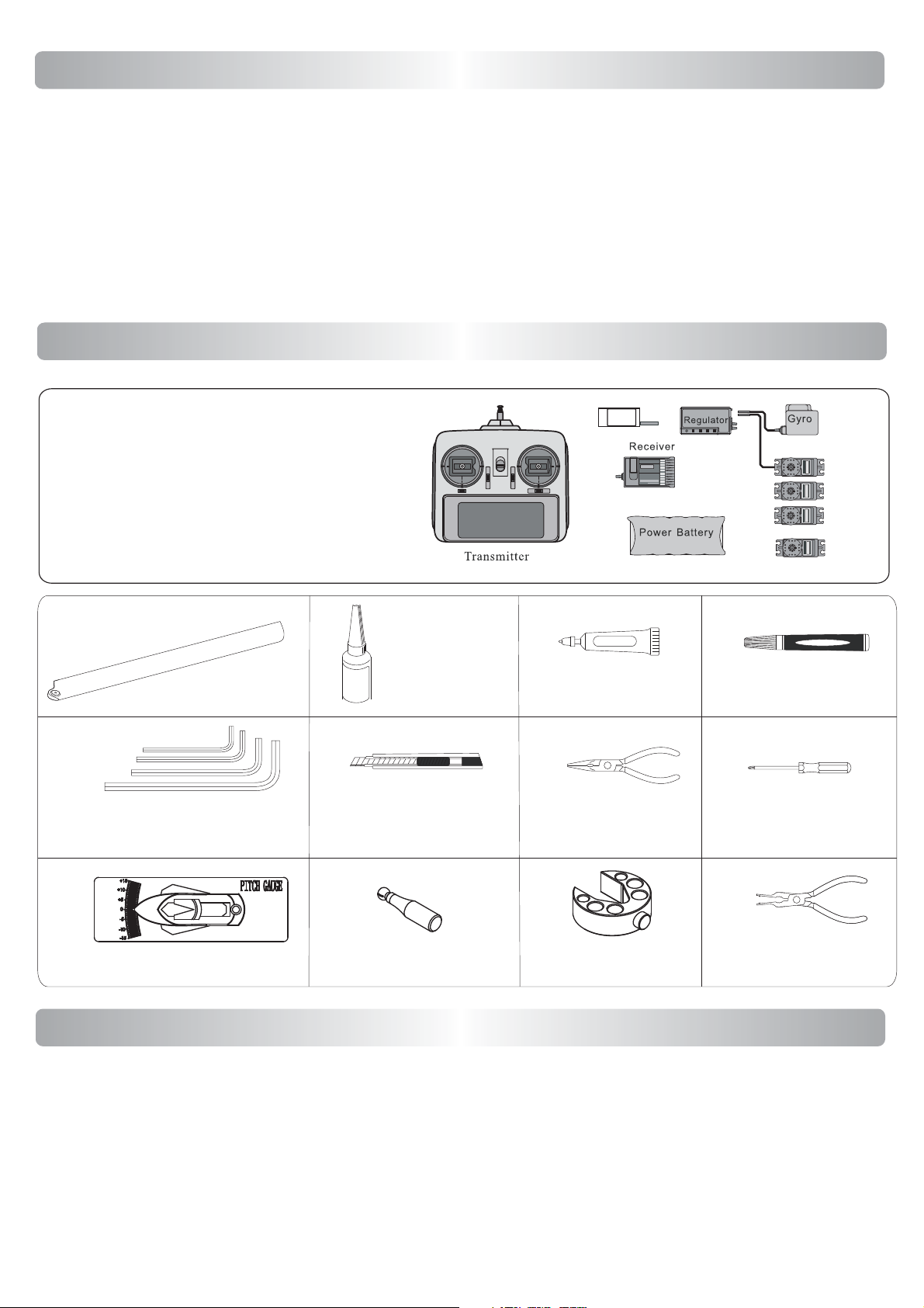
Necessary Items
In order to operate this model, you need to purchase the following items not kit-included.
6 channel or up radio and receiver.
3 standard servos.
1 rudder servo.
1 Flybarless Unit
1x LiPo Battery 12S or 2 6s Packs
1x HV BEC or Receiver Battery
Main Rotor
Length: up to 710mm
Hex Wrench Set
(1.5mm,2mm,2.5mm,3mm, 5mm)
Threadlock
Cutter Knife
BEC
Grease
Needle Nose Pliers
Standard Servos
Bearing Retainer
Phillips Screw Driver
Pitch Gauge
Ball Link Sizing Tool Ball Link
Swash Plate Tool
Plier
Pre-assembly Information
When first opening your Atom kit, you will notice that all of the parts are packaged and numbered to coordinate with the
assembly step numbers of this instruction manual. All small hardware (nuts, bolts, washers, etc.) for each step are packaged
separately within the main parts bags. When beginning a section, you will need to open only the bag with the corresponding
number to the section you are about to start. It is suggested that you place all of the hardware in an open container (e.g., servo
case) during assembly so as not to lose any of the small parts. It may also be helpful to familiarize yourself with the various
sizes of screws, bolts, nuts, etc., as illustrated in the appropriate assembly section before you begin assembly. In most cases, at
the end of each assembly section, there should be no parts remaining. Great care has been taken in filling the bags with the
correct quantity of parts and hardware for each section. However, occasional mistakes happen. In the event that you find a
parts shortage or are in need of technical assistance, please contact your local Compass Model parts dealer.
Page 5
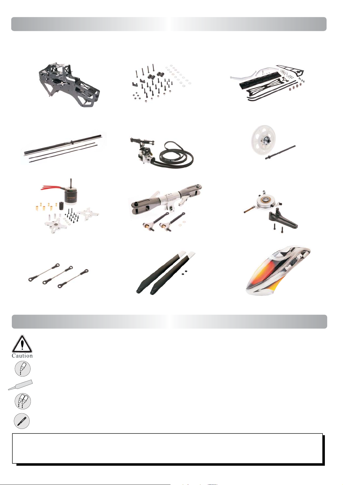
In The Box
This model is packed according to assembling steps. Do not open all the bags at one time.
Open only one bag for each step of assemply when building.
Frame Set
Step 3 Tail Set Step 4
Motor Set
Step 1 Step 2
Rotor Set
Swash Set
Linkages
Blades
Canopy
Symbols & Assembling
Mishandling due to failure to follow these instructions may result in damage, personal injury or danger.
Use Blue Threadlock
G
Use Grease
A
B
Use AB Glue
Use Bearing Retainer
* Always apply blue Threadlock when fixing Bolts on Metal parts.
* Always apply green retainer where bearings has to be fit into metal parts.
* Do not over-tighten self tapping screws into plastic parts or you will strip the threads!
Page 6
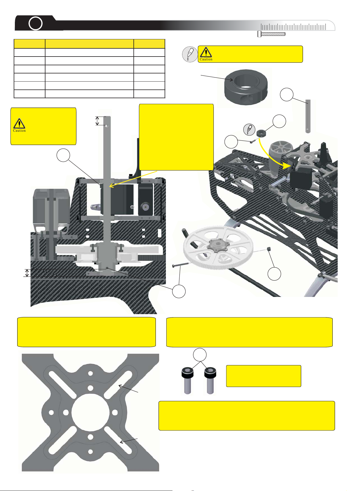
1
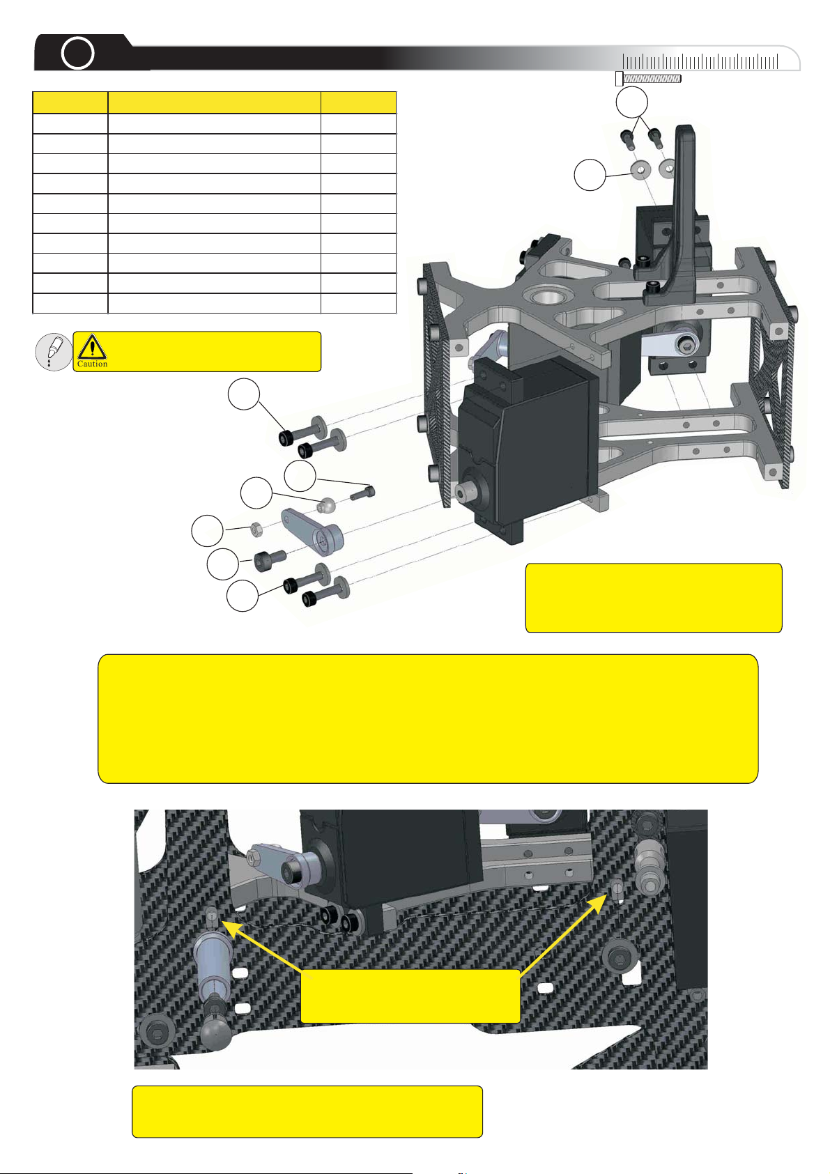
Pos Description Qty
1 M2.5x10 Socket Head Bolt 12
1 M2.5x12 Socket Head Bolt 12
2 M2x8 Socket Head Bolt 4
3 Stainless Ball 4
4M2Nut 4
5ServoBolt 4
6 Servo Spacer 2
7 M2.5x20 Socket Head Bolt 4
8ServoNut 2
9 2.5mm Washer 12
Servo
Use medium threadlock on all
screws going into metal parts
Swashplate Servo
0
10
1
9
1
30
20
40
Installation
For mounting the swashplate servos to the bearing blocks, tighten all bolts of the upper bearing block
with medium threadlock. Fix the servos at the upper bearing block. Install the main shaft through all
bearing blocks and push the middle bearing block up against the bottom of the cyclic servos. Tighten the
four screws in the X-shaped parts that secure the middle bearing block. Now slide the main shaft up and
down to make sure the bearing blocks are all aligned. If the main shaft doesn't slide freely, loosen the
screws of the bearing blocks and tight them in a cross pattern. The bearing blocks must be aligned
parallel to each other. You can control this by comparing the height of the bearing block in the long holes
of the side frame. Do not forget to apply new threadlock when loosened a screw!
2
3
4
5
1
The Servo installation is done without
the supplied Servo Rubbers. If you
want to use the Rubber, please use
M2.5x12 Bolts, instead of M2.5x10.
Remove the black cap of the canopy standoff to loosen
and tighten the screw for adjusting the bearing block.
Use these long holes to adjust
the middle bearing block to fit
different servos.
Page 7
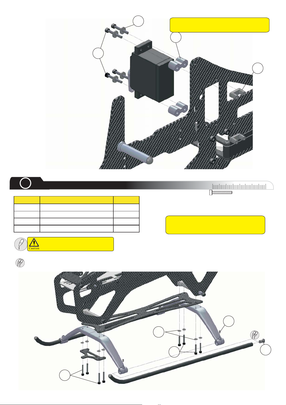
Pos Descripti on Qty
1 M3x20 Socket Head Bolt 8
2 3mm Washer 8
3 3x5mm Set Screw 4
4SkidCaps 4
Tail Servo
Installation
9
Tip: Do not over tighten the four servo
screws as it may damage the plastic parts.
6
7
8
2
A
B
Use AB Glue
Landing Gear
Use medium threadlock on all
screws going into metal parts
0
10
30
20
Tip: Do not over tighten the four 3 x 5mm
set screws as it can damage the landing
struts.
40
1
3
A
2
1
B
4
Page 8
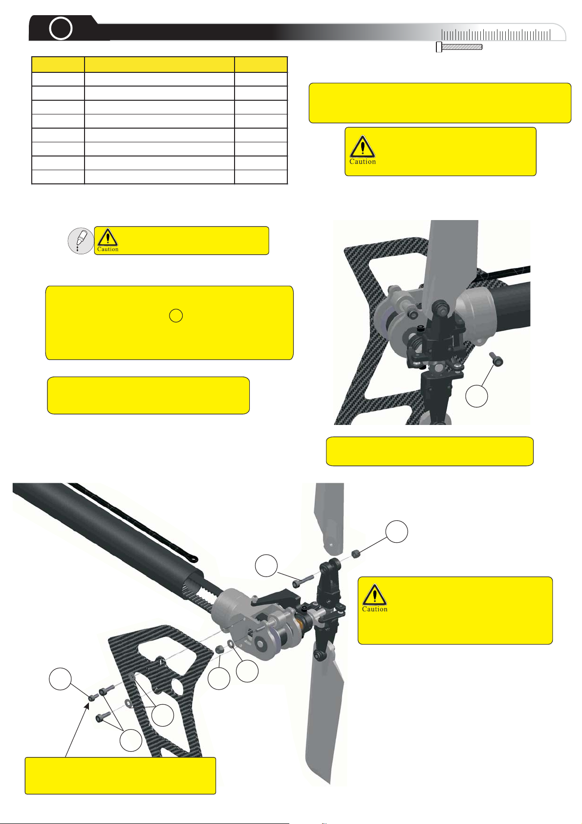
3
Pos Description Qty
1 M3x75 Socket Head Bolt 4
2 3mm W asher 11
3M3NylonNut 8
4 M3X16 Socket Head Bolt 2
5 M3X25 Socket Head Bolt 3
6 M3X10 Socket Head Bolt 3
7 Boom Support Collar 2
8 M2.5X6 Socket Head Bolt 2
Slide the tail case completely onto the boom, align it to
the Compass writing and fix it with the clamp on the rear
side. The two locking bolts ( 8 )must be screwed
completely into the case to pierce the boom. After this
step, the angle of the writing can not be adjusted any
more!
Boom & Tail Rotor
Use medium Threadlock on all
screws going into metal parts
0
10
To pull the belt through the tail boom, slide a cord through
the boom and fix the belt very carefully at the cord. You can
also use a strand and bend a hook at one of the ends.
Crimping the belt damages the
tensile cords and will result in
premature failure!
30
20
40
Tip: Do not tighten the bolt of the belt
idler pulley yet, it will be adjusted later.
6
Tip: You can use a very small drop of thin
CA glue to secure the pin in the tail pulley.
3
4
Be careful not to over tighten the
bolts when attaching the tail rotor
blades. The tail blades should be
able to move with a slight amount
of resistance within the tail blade
holders.
8
3
Take special care to get the boom long
enough into the tail assembly for correct tail
length before you tight this bolt.
6
2
2
Page 9
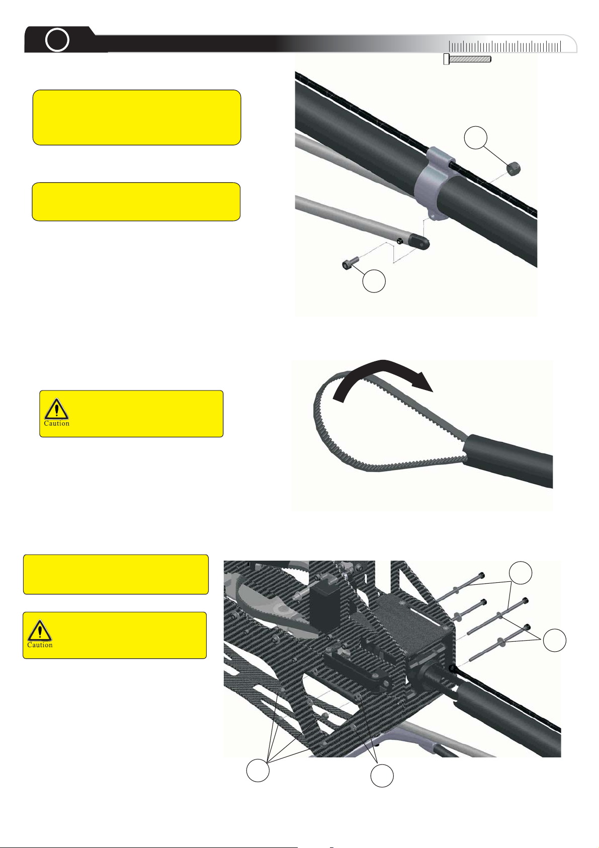
3
Boom & Tail Rotor
Tip: Slide the tail boom clamp over the
boom. Unscrew one of the ball links on the
tail control rod. Screw it back on the
control rod after installing it.
Tip: Just instal l the screw, struts and nut
temporary without tightening them to
much.
0
10
3
5
30
20
40
Twist the tail belt 90° to the
right before inserting it
between the idler pulleys.
Slide the Tail Boom through the tail
boom mount and between the idler
pulleys
Do not crimp the tail belt and
be sure that it is not turned in
the wrong direction or more
1
2
3
2
Page 10
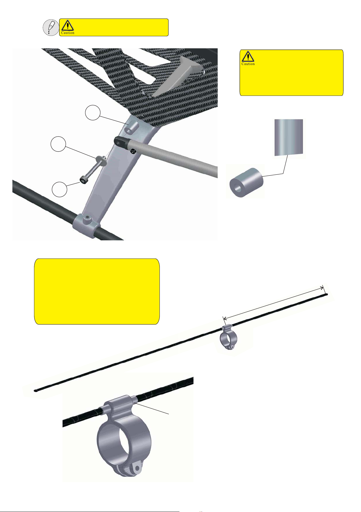
Use medium threadlock on all
screws going into metal parts
The boom support collar (7)
has one beveled side. This
must face outside. Be careful
when fixing the tail boom
braces and arrange the
collars to them.
7
2
Beveled Side
5
Tip: Clip on the ball link on the tail
control arm. Look which part of the tail
control rod slides in the guide of the tail
boom clamp to get the correct position for
the heat shrink. Clip it off again and pull
the tail control rod as far as possible to the
rear. Slide the heat shrink over the tail
control rod and shrink it carefully with a
lighter.
Heat Shrink Plastic
m
m
0
3
1
Page 11
4
Pos Description Qty
1 Main Shaft Clamp 1
2 M2.5x 10 Soc ket Head Bolt 1
3MainShaft 1
4 M3X30 Sock et Head Bolt 1
5M3NylonNut 1
6 M4x10 Socket Head Bolt 2
Main Gear
rim
0
10
20
Use medium threadlock on all
screws going into metal parts
3
30
40
Do not over
tighten the screw
in the main shaft
clamp, but fix it
securely.
8.5mm
After installing the main
11mm
1
gear, mount the main
shaft clamp below the
upper bearing block with
the rim facing towards
the bearing. Push the
main shaft down and the
main shaft clamp up. The
must be zero clearance.
1
2
5
If you have to change the main gear, do not
overtighten the bolts going into the hub or it may
draft the main gear. Tighten the bolts in a cross
pattern.
4
To intall the main gear, push the tail boom all the way in.
Pull the tail belt out at one side of the chassis and mount it
on the main pulley. Then slide the main gear into the frame
and align the holes over each other to fit the jesus bolt.
6
2 extra M4x10 Bo lts are
equipped here in case for
optional motors.
4mm slot
To mount Motors with different hole measurements, use 2 of
the 4 slots in the motorplate. The 4mm slots for motors with
M4 screws and th e 3mm slots for motors with M 3 screws.
Only 2 screws are necessary in this case.
3mm slot
Page 12

Motor And Drive Tips
Use medium threadlock on all
screws going into metal parts
Gear backlash adjustment:
For smooth operation and
performance, it is necessary to adjust
the gear backlash properly. Excess
gear backlash can cause premature
gear wear and damage. Insufficient
gear backlash can cause vibration, as
well as overheating of the Motor and
speed controller. Adjust the gear
backlash by placing one piece of
paper between the gears to set the
distance. When the bolts are secure,
remove the paper and test the gear
backlash to insure that there is a
slight amount of free movement
between the gears.
To adjust the correct backlash between
the motor pinion and the main gear
loose the 4 motor mount bolts on each
side , then fix them tightly with
threadlock.
Tip: Use a pressure resistant extra sticky grease on the maingear to reduce abrasive wear and
noise. Grease it every five flights for the first 20 flights. Check the gear backlash especially in the
first 20 flights. Apply some grease when you recognize that the main gear gets „dry“.
Tip: Choose a low kv motor so you can use 14t or higher pinion for good contact with the main gear
to prevent excessive wear on the main gear.
Motor Setup And Maintenance Tips: Use at least 5.5mm gold connectors with an even
surface for your motor wires and ESC wires. Use heat shrink and look for a good isolation. Check
all wires and connectors regularly for good fitting and damage. Damaged wires and connectors can
cause severe damage to your model and equipment! Oil the motor bearings each 10 flights and
change them if they make strange noises or when the motor gets clearance at the shaft or bell.
Soldering Tips: Use a soldering iron with atleast 80W and SN60PB40 brazing-solder. The
temperature should be around 380°C. Use a non-conductive heat resistant surface and clamps or
pliers to hold the connectors and wires. Do not heat the connectors and wires to long. The braze
point must be shiny and even. If you have problems with the soldering, ask a experienced modeler
for help. Due to extreme high currents of up to 200Amps and mechanical stress to the connections,
good soldering points are very important to guarantee a safe function of your power system.
Page 13

Use blue threadlock on all
screws going into metal parts.
swing range
Tip: Check the rubber from time to time
for cracks and refractory material.
Tip: Fix the tail boom clamp later, so you
can adjust the angle for a perfect smooth
running tail control.
Tip: If the rubber gets older,
you can increase the tension
by opening the two screws in
the holder and sliding it to the
rear in the long holes.
Adjusting the belt tensioner is pretty easy. Just
remove the rubber ring and adjust the tension as
usual. After remounting the band, the tensioner
should swing in 1/3 of his possible travel– if it
swings more in then the tension is to lose.
Increase it by removing the band again and move
the tail boom further to the rear. Use the four
screws in the tail boom mount to fix the boom.
Check the belt tension sometimes.
Readjustments may be needed after a while or
big temperature differences.
Adjust the belt idler pulley with a distance of
0.2-0.3mm to the tightened belt. Do not over
tighten the screw as it may result in a bent tail
case and sluggish bearings.
Page 14

5
Pos Descripti on Qty
1 M4x25 Socket Head Bolt 1
2 M4x30 Socket Head Bolt 2
3 Preassembled Rotor Head 1
4 3mm Washer 4
5 4x8x3 Flanged Bearing 4
6M4NylonNut 1
7 M3x14 Socket Head Bolt 2
8 Swashplate Guide 1
9 M2.5x10 Socket Head Bolt 2
Rotor,Washout & Swashplate
0
10
30
20
40
Use medium threadlock on all
screws going into metal parts
Mount the mainrotorhead
using the upper hole
VERY IMPORTANT:
Be careful not to
overtighten the two
clamping screws (7) in
the main rotor hub.
1
3
2
4
5
5
4
6
The Jesusbolt (6) just
carries the torque.
Tighten it firm but do
not use to much force.
Do not overtighten the two
M4x30 socket head bolts (2)
as it may result in sluggish
bearings in the A-arm
Install the linkage for the
elevator servo at the
swashplate before you
mount the swashplate
guide.
The feathering/spindle shaft
screws are not secured. You
have to clean the shaft from
the inside and the screws
with alcohol and secure them
tightly with threadlock!
Use some light oil on the
main shaft for a smooth
travelling swashplate and
clean it regularly.
7
9
8
Main grips are factory preassembled; in case of reassembling
make absolutely sure you use the correct “ID”(inner diameter)
ring at the correct position. Place the large ID towards the main
shaft and the small ID towards the blades during assembly.
Thrust Bearing Direction
Main Grip
Apply Grease Here
Larger ID
(IN)
Smaller ID
(OUT)
Page 15

6
Suggested Equipment Position
Take some time for the wiring.
Good fixing of the components
and wires is important for a safe
operation of your rc-equipment.
Read the following wiring tips
carefully.
Brushless Motor
Esc
Aileron
Pitch
0
Elevator
10
Rudder
30
20
40
12S Battery
Please read the manual of your
FBL-Unit, transmitter and
receiver very attentively. Each
FBL-Unit is different, follow the
manuals step by step and ask for
help if you have problems with the
programming and installation.
Receiver
FBL Unit
ESC
BEC
To M o t o r
FBL
Ch6
Page 16

7
Linkage Length & Setup
00
00
10
30
20
40
Do not apply plier to resize Ball Links. Pliers could
cause hidden damage to Ball Links and result in
failure when operation.
Use medium threadlock on all screws
going into metal parts and nuts.
Do not use pliers or screwdrivers to
screw the ball links onto the linkages.
It can damage the ball links and
result in failure. Screw them on by
hand or use special tools.
1
7
.
5
m
m
Compass Model ball links are build up on
the tight side. This allows you to adjust them
to your personal needs. Use a ball link
sizing tool to adjust the ball links. Clip the
ball link on the corresponding ball where it
will be later and test if it moves freely. If not,
clip it on the ball link sizing tool and rotate it
a few turns in different angles. Test it again
on the ball. When you level the whole
linkage horizontally, the linkage should
almost flip downwards by ist own weight. Do
the resizing in small steps and test the
fitting every time. If any ball link has
clearance on the ball, change it and do not
use it again.
All ball links must be clipped on the
balls with the Compass writing
facing to the outside.
Check all ball links for clearance
and damages everytime you go
flying and change worn ball links
early.
Tip: You can make your own ball link sizing tool. Just use a Dremel with a
thin cutting wheel to cut two slots opposite to each other into a ball
you don´t need. Stick a screw through the ball and screw a nut on the
other side to fix the ball. You can clip ball links onto this tool and use
it as described above.
5
0
.
5
m
m
The length of the
plastic drive tube can
be changed easily by
turning the ball link in
5
and out.
4
.
2
5
m
m
Linkage Lengths:
Servo Horn to Servo center: about 17.5mm
Servo to Swash: about 57mm inner edge to inner edge
Swash toA connector: 58mm inner edge to inner edge as per
picture.
Page 17

Tail Setup
Headspeed 1400-1800 Headspeed 1800-2100
Travel A Trav el B Travel A Travel B
Stock Plastic 2mm 17mm 2mm 16.5mm
KB DD 104m m 2mm 17mm 2mm 16. 5m m
Compass 115mm 3.5mm 16mm 4mm 16mm
Mo st CF 10 5mm 3mm 17mm 3mm 16. 5m m
90°
1
1
7
7
.
.
5
5
At zero position, the servo arm should
be at 90°. Use the b est fitting servo
arm and read the manual of your FBLUnit how to adjust the servo midposition.
Adjust the linkage length so that the slider is
parelel to the tail case side wall.
It is important to limit the servo travel to the endpoints of the slider shown below. Too much
travel can cause a stall and lead to a loss of tail authority.
A
Clockwise Position
Set the limit of the tail servo to A from slider to
bearing.The table blow gives the value of Afor
different blades and rotor head rpm.
With the tail pitch slider in this position, the
helicopter will turn clockwise.
Counter Clockwise Position
Set the limit of the tail servo to B from slider to
bearing.
different blades and rotor head rpm.
With the tail pitch slider in this position, the
helicopter will turn counter clockwise.
The table blow gives the value of B for
B
Adjusting the gyro direction:
To adjust the gyro direction, read the manual of your fbl unit. Look at the heli from behind.
When you turn the nose to the left (counter clockwise), the tail pitch slider must go towards the tail rotor hub
and away from the tail case.
When you turn the nose to the right (clockwise), the tail pitch slider must move towards the tail case and the
bearing.
Doule check this step!
Page 18

Wiring Tips
Never use RC-components with damaged
wires. Check all wires for damaged isolation
and breakage. Control all servo connectors for
a tight fit and be sure no wire is loose in the
connector.
All wires must be protected against damage
through sharp edges of the carbon frame and
metal parts. Zip ties can also cause damage to
the wires.
Tip: Cut open a piece of fuel line to cover sharp edges.
You can also use fuel lines to cover zip ties to
prevent them from damaging the wires.
Carbon fibre and metal parts are
conductive . Open wires, contacts and
open gaps between two contacts
touching the frame can cause a short
curcuit and damage to the RC-Equipment.
the RC-Equipment.
Tip: The be st way t o protect your wire s is to us e
braiding sleeve such as those used for
computer wiring or casemodding. Seal the
ends of the sleeve with heat shrink to prevent
them from unraveling. You can also you use
heat shrink to protect wires where zip ties
overlie.
Keep all wires as short as possible. Avoid unnecessary extensions and connections, but use extensions if a
wire is almost to short to avoid mechanical tension in the wiring. Never tighten a wire to much. Be sure that
nothing pulls at a wire. It is very important to have zero tension between wires, plugs and RC-Components.
Do not pull out connectors by pulling at the
wires!
Do not fold any wire, place them in curves.
Tip: Secure connectors with heat glue at the receiver and
Keep all wires away from rotating parts,
linkages and servo arms.
Tip: Use a plier to bend zip ties before you use
them. It wil be easier to get them around a corner.
FBL-Unit. Avoid contact of the glue with stickers and
the wires. The glue is easy to remove.
Be careful when heating heatshrink on wires,
don´t heat it up to long or with to much heat
or it may damage the isolation.
Control all wires and connections regularly to discover hidden damages and defective
contacts early. Never go flying if any failure occurs!
Page 19

FBL Setup Tips
Please read the manual for the current
software version of your FBL-Unit carefully
and follow all instructions. We can't give
you any specific tips because most brands
of FBL-Units change their software from
time to time and your setup depends on
many other factors like used blades and
servos. Please check our website to find
some setups from our Teampilots.
Tip: All servo horns must be at 90° (horizontally). Try all
possible positions of the servo horn to get as close as
possible to 90° at neutral servo position. Keep all
swashplate linkages at exactly the same length. Level
the swashplate horizontally in all directions, therefore
read the manual of your FBL-Unit and follow the
instructions!
Tip: For easy measurement of the pitch angles
during the setup, please use something long
and straight (like a flybar or CF-Tube) and put it
on the upper servo mount behind the servorods.
With this trick you can easily use the pitchgauge
to check the collective and cyclic angles.
If you have vibrations it is better to find the source than using a softer tape.All wiring to the FBL-Unit must be
done without tension and not to stiff. If you use some kind of cover to protect the wires, please remove it on the
last 3-5cm to make sure that vibrations can’t be carried to the unit – which will cause strange behaviour like
unwanted movements of the helicopter.
Remove all kind of grease and oil from the radio tray and the bottom of the FBL-Unit with alcohol or something
similar.
Please place your FBL-Unit extremely carefully in your helicopter. It is important that the unit is in a perfect 90°
angle to all axes to get best performance. Awrong mounted unit can cause a wobble during piro-manouvers.
A perfect CG (Center of Gravity) is very important to get a perfect flying model. The CG must be
exactly under the mainshaft. Adjust the CG by positioning the battery to the front or to the rear on
the battery tray. You can also change the position of the battery tray with the three mounting holes
in the side frames. The CG should be measured with all parts including the canopy.
Tip: There are two methods to find out where the CG is. The first method is to hold the model under the main
blade grips and look if it tilts forwards or backwards.
You can also hold the model at the main blade grips and fixed main rotor blades with the main shaft
leveled horizontally. Look with the canopy facing to the right and then facing to the left (due to the free
wheel) if the nose or tail tilts down.
If the nose tilts down, you have to put the battery more to the rear, do the opposite when the tail tilts
downwards.
Page 20

FBL Setup Tips 2
Look at the helicopter from the side to test
the gyro direction.elevator
Double check the gyro directions of your fbl unit!
Incorrect gyro directions will cause a crash!
Checking the swasplate and tail gyro
directions is a part of the preflight check!
Tilt the helicopter forwards as shown in the
picture. The swashplate must tilt backwards.
Watch the helicopter from the front/canopy
to test the gyro direction.aileron
Tilt the helicopter backwards as shown in
the picture. The swashplate must tilt forwards.
Tilt the helicopter to the left, the swashplate
must tilt to the right as shown in the picture.
Tilt the helicopter to the right, the swashplate
must tilt to the left as shown in the picture.
Page 21

8
The picuture below shows how the swashplate has to move in mode 1 or mode 2.
Control Check
Mode 1
Mode 2
Aileron Check
Swashplate Reaction
Tilt Right
Tilt Left
Tilt
Forward
Tilt
Backward
Elevator Check
Pitch Check
Ascent
Swash Plate
Descent
Tail Pitch Plate
Rudder Check
Slide left
Slide Right
Page 22

9
Pos Descripti on Qty
1 M2.5x8 Self Tapping Bolt 2
2 Canopy Insert 1
3 M3x8 Socket Head Bolt 2
4 Thumb Screw 2
5 Canopy Rubber Grommets 2
ABA
B
Use AB Glue
Canopy
Place the canopy onto the frames
and mark the right position of the
canopy insert. Mark the positions
of the holes in the anopy on the
Insert for drilling. Use a 2mm drill
and drill straight through the
insert. UseAB glue to fix the insert
and screw it from the outside into
the canopy.
00
00
10
4
ABA
B
30
20
40
1
2
3
5
10
Grounding
Belt-driven tailrotors can produce a high amount of electricity.
The discharge can cause a blockage of the radio signal and the
RC-Components. If you have transmission problems and/or
problems like hard tail kicks and lockouts during flight, you have
to ground the tail. We recommend to ground each helicopter for
safety reasons if you are not sure if everything works without
failures.
To ground the helicopter, use a piece of fine sandpaper to remove a little bit of
the black anodizing between the two tail boom clamps in the frame with care. Do
not modify the tailboom behind the tail boom clamps! Use a piece of silicon wire
with a diameter of at least 1mm² and skin one end. Attach the open end to the tail
boom with one or two zip ties. Lay the wire to the motor, skin the other end and
attach the wire to one motor screw by jamming the open end under the screw.
00
00
10
30
20
40
Do not use a file, rasp, knife or
coarse sandpaper to remove the
anodizing. Deep scratches will
damage the structure of the tail
boom and can cause a breakage
of the tail boom!
Page 23

00
00
10
11
Rotor Direction & Blades
20
When the main rotor spins clockwise the tail blades should
turn clockwise as well watching the tail rotor from the tail fin
side. If not, the belt is twisted and has to be corrected.
Be sure that the main rotor and tail rotor blades are installed in
the right direction. The leading edge has to show into the rotor
directions.
Do not overtighten the blades. The main rotor blades should not be able to retract when you hold the
helicopter sideways with the mainshaft and both blades horizontally. Do not thighten the blades much
stronger than this and use the washers delivered with the blades.
30
40
12
Do not grind the blades if they
don´t fit.Ask the manufacturer
for other washers.
Blade Tracking
Use the same amount of washers
with the same thickness over
and under the blades!
00
00
10
20
30
The get a helicopter without vibration issues and, perfect flight abilities and low power consumption, you
have to track the main rotor blades. The first step is to have identical lengths from the end of the ball link
on the plastic drive tube to the metal arm.
In most cases, the blade tracking will be fine after doing this. To check it during the flight, get the help of
an other pilot for safety reasons. Get in a hover and ask him to watch the rotor disk. Both blades must be
in one line. If there are two disks or the blades appear thicker than they are, you have to readjust the
blade tracking by turning in and out the ball links in the plastic drive tubes. Mark one blade or blade grip
and turn in or turn out the ball link of this blade by one turn. Remember the direction. Hover the
helicopter again, if it gets worse, turn back the ball link and rotate it one turn in. If it get´s better but is not
perfect, turn the ball link of the other blade out by one turn and hover again. The blade tracking should
be perfect now. If not, an issue with the rotor blades is likely. Do not fly with these blades. Also check all
linkages, balls, ball links and the swashplate links for clearance.
40
Do not check the blade tracking
on the ground alone or with
negative pitch.
Read the following pages before
you go to test thi s!
Do not fix the helicopter to the
ground or any object.
Keep some distance to the
model and do not test this
indoors!
Page 24

COMPASS MODEL (HK) LIMITED
www.compassmodel.com
Page 25

Parts List
7 HV
Version 3.0/2012
Copyright @Compass Model 2012
As we continue to improve our products, this part list may not reflect all recent product amendments.
For more information, please refer to www.compassmodel.com
Page 26

91-0004
80-0312
09-7067S
09-0109
80-0421
82-4264
80-0430
05-0119
09-7101
05-0117
80-0325
80-5285
09-7069S
09-7025S
79-0512
82-5131
60-8165
82-821003
63-8165
05-0102S
91-0005
09-7068S
80-0304
80-0312
82-4264
09-7067S
09-7068S
61-4083
09-7069S
05-0102S
81-0328
02-0709S
09-7025S
Page 27

Part No. Part Description Qty,
02-0709S Ball Links
05-0102S Metal Main Grips 7Hv 1 pcs/bag
05-0117 Spindle
05-0119 Spindle Washer (90)
09-0109 7Hv Dampner 2 pcs/bag
09-7025S 7Hv Fbl Drive Tube 1 pcs/bag
09-7067S 7Hv Center Hub 1 pcs/bag
09-7068S 7Hv Main Grip Arm 1 pcs/bag
09-7069S 7Hv Fbl Arm Connector 1 pcs/bag
09-7101 7Hv Fbl Connector Collar 2 pcs/bag
60-8165 Ball Bearings 8X16X5
61-4083 Flanged Bearings 4X8X3
63-8165 Thrust Bearings 8X16X5
79-0512 Button Head Bolts M5X12
80-0304 Cap Head Bolts 3X4 2 pcs/bag
80-0312 Cap Head Bolts M3X12
80-0325 Cap Head Bolts M3X25
80-0421 Cap Head Bolts M4X21
80-0430
80-5285 Shanked Bolts M5X28.5
81-0328 Set Screws M3X28
82-4264 Washers 4.2X6X0.4
82-5131 Washers 5.1X13X0.1
82-821003 Washers 8.2X10X0.3
91-0004 Nylon Lock Nuts M4
91-0005 Nylon Lock Nuts M5
Cap Head Bolts M4X30
10 pcs/bag
2 pcs/bag
2 pcs/bag
2 pcs/bag
4 pcs/bag
2 pcs/bag
10 pcs/bag
10 pcs/bag
10 pcs/bag
2 pcs/bag
10 pcs/bag
2 pcs/bag
10pcs/bag
10 pcs/bag
10 pcs/bag
10 pcs/bag
10 pcs/bag
2 pcs/bag
Page 28

02-5264
90-0201
91-0003
60-4094
91-0003
60-3092
82-3402
63-4094
02-0264AB
80-0314
02-0225
09-7048
60-7113
02-1211
02-8205
60-7113
05-0229S
02-0214
80 0310-
06-0222
02-0213
80-0208S
02-0209
02-0701
80-0338
61-5134
81-0305
02-0205
84-0214
80-0208
98-2040B
82-327408
91-0003
06-0223
09-8023
09-7023
09-8051
09-7079
06-0223
80-0310
09-7051
09-7075
09-7066S
09-7050
09-7007
82-3201
80-0310
80-2510
Page 29

Part No. Part Description Qty,
02-0205 Tail Blade Links W. Pin
02-0209 Tail Rotor Hub 1 pcs/bag
02-0213 Tail Pitch Slider
02-0214 Tail Shafts
02-0225 Grooved Pin 2X10 4 pcs/bag
02-0264AB Tail Blade Holder Set 2 pcs/bag
02-0701 Stainless Link Balls 10 pcs/bag
02-1211 Tail Pitch Plate W, Bb 1 pcs/bag
05-0229S Tail Pitch Slider W,Bb 1 pcs/bag
06-0222 Guide Pin Bolts
06-0223 Pin 2X24 4 pcs/bag
09-7007 Tail Fin
09-7023 Tail Pitch Connector
09-7048 Tail Pitch Arm
09-7050 Tail Gear Box Frames
09-7051 Tail Gear Box
09-7066S Tail Guide Wheel
09-7075 Tail Pulley
09-7079 7hv Tail Hinge
09-8023
09-8051 7Hv Metal Gear Box
02-8205 Tail Pitch Control unit
02-5264 Tail rotor hub assembly (plastic)
60-3092 Ball Bearings 3X9X2.5
60-4094 Ball Bearings 4X9X4
60-7113 Ball Bearings 7X11X3
61-5134 Flanged Bearings 5X13X4
63-4094 Thrust Bearings 4X9X4
80-0206s Cap Head Bolts 2X6
80-0208 Cap Head Bolts M2X8 10 pcs/bag
80-0208S
80-0310 Cap Head Bolts M3X10 10 pcs/bag
80-0314 Cap Head Bolts M3X14 10 pcs/bag
80-0338 Cap Head Bolts M3X38 10 pcs/bag
80-2510 Cap Head Bolts M2.5X10 10 pcs/bag
81-0305 Set Screws M3X5
82-327408 Washers 3.2X7.4X0.8
82-3402 Washers 3.3X5.2X0.3
84-0214 Spring Pin 2X14
90-0201 Nuts M2
91-0003 Nylon Lock Nuts M3
98-2040B 3M 8Mm Wide 2040 Belt
7Hvtail Pitch Lever Set
Cap Head Bolts 2X8 special made
for ball
2 pcs/bag
1 pcs/bag
2 pcs/bag
2 pcs/bag
1 pcs/bag
1 pcs/bag
1pcs/bag
1 set/bag
1 pcs/bag
1 set/bag
1 set/bag
1pcs/bag
1 set/bag
1 set/bag
1 set/bag
1 set/bag
4 pcs/bag
5 pcs/bag
2 pcs/bag
2 pcs/bag
2 pcs/bag
10 pcs/bag
10 pcs/bag
10 pcs/bag
10 pcs/bag
10 pcs/bag
10 pcs/bag
10 pcs/bag
10 pcs/bag
1 pcs/bag
Page 30

80-0332
09-7058
09-7102
60-6155
09-7053
07-4312(12T)
07-4313
07-4314(14T)
81-0404
80-0410
(for optional motors)
80-0308
09-7059
08-4928
60-8196
02-0701S
05-0606S
80-0310
05-0602Z
60-15245
05-8401
02-0701
80-0225
09-7056
09-7103
60-17265
62-162216
05-4602
08-4926
60-8196
08-4927
C-4926
80-0512SS
80-2508
91-0004
81-0404
80-0308
09-7026
09-7070
80-0430
Page 31

Part No. Part Description Qty,
08-4926
Motor Shaft for 4926 motor
1pcs/bag
02-0701 Stainless Link Balls
02-0701S Solid Link Balls 10 pcs/bag
Autorotation Hub W,One Way
05-0602Z
05-0606S Mast Lock Clamp
05-4602 Main Gear 1pcs/bag
05-8401 7Hv Swash Plate 1set/bag
07-4312 Pinion Gear (12T) 1 set/bag
07-4313 Pinion Gear (13T) 1 set/bag
07-4314 Pinion Gear (14T) 1 set/bag
09-7026 7Hv Main Pulley
09-7053 7Hv Motor Mount Spacer 3pcs/bag
09-7056 Swash Plate Pin
09-7058 7Hv Motor Mount Top
09-7059 7Hv Motor Mount Bottom
09-7070 Main Pulley Hub
09-7102 7Hv Main Shaft
09-7103 Autorotation Sleeve
Bearing
10 pcs/bag
1pcs/bag
1 pcs/bag
1pcs/bag
1set/bag
1 pcs/bag
1 pcs/bag
1 pcs/bag
2pcs/bag
1pcs/bag
08-4927 Motor shell for SZ4926
08-4928 Motor cover for SZ4926
60-15245 Ball Bearings 15X24X5
60-17265 Ball Bearings 17x26x5
60-6155
60-8196
62-162216
80-0512SS
80-0225 Cap Head Bolts 2X25
80-0308 Cap Head Bolts M3X8
80-0310 Cap Head Bolts M3X10
80-0332 Cap Head Bolts M3X32
80-0410 Cap Head Bolts M4x10
80-0430 Cap Head Bolts M4X30
80-2508 Cap Head Bolts M2.5X8 10 pcs/bag
81-0404 Set Screws M4X4 10 pcs/bag
91-0004 Nylon Lock Nuts M4 10 pcs/bag
SZ4926 12S Motor for 7hv kv510 1 pcs/bag
Ball Bearings 6X15X5
Ball Bearings 8x19x6
One way bearing 16x22x16
Stainless Cap Head bolt M5x12
1pcs/bag
1pcs/bag
2 pcs/bag
2 pcs/bag
2 pcs/bag
2 pcs/bag
1 pcs/bag
2 pcs/bag
1pcs/bag
10 pcs/bag
10 pcs/bag
10 pcs/bag
10 pcs/bag
10 pcs/bag
Page 32

85-0001
a:78-0310
b:80-0308
c:80-2506
d:82-3201
e:91-0003
09-7018
09-7042Z
a
09-7001Ra
09-7073
09-7011
60-10195
80-0375
b
a
d
a
d
09-7005
a
80-2520
09 7024-
02-0918
a
e
a
09-7004
09-7045S
09-7002a
09-7008S
a
09-7044
a
09-7060
79-0310
d
b
09-7001L
a
80-0306
09-7092
d
d
b
d
e
b
b
b
09-7109
d
c
b
d
d
b
c
e
d
d
b
d
d
d
b
b
d
c
c
b
02-0820
09-7061
09-7055
d
d
80-0310
91-0003
80-0325
09-7082
79-0306
d
e
d
e
09-7062
80-0322
82-3507
60-3095
09-7064
09-7071A
60-3095
82-3507
80-0330
09-7078S
79-0308
82-3504
61-3062
09-7009
82-3507
09-7062
09-7009
61-3062
79-0308
91-0003
09-7081
79-0310
09-7078S
78-0310
Page 33

Part No. Part Description Qty,
p
g
02-0820 Skid End Caps
02-0918 Servo Nuts
09-7001La Upper Frame Left 1 pcs/bag
09-7001Ra Upper Frame Right 1 pcs/bag
09-7002a Lower Frame
09-7004 Receiver Mount 1 pcs/bag
09-7005 7Hv Gyro Mount
09-7008S Battery Tray 1 set/bag
09-7009 Guide Wheel Frame 2 pcs/bag
09-7011 Canopy Break-Off 2pcs/bag
09-7018 Battery Lock 1 set/bag
09-7024 Servo Spacer
09-7042Z Bearing Block W, Bearing 1 set/bag
09-7044 Battery Tray Connector
09-7045S Receiver Stand Off
09-7055 Boom Support Collar
09-7060 7Hv Boom Clamp
09-7061 Battery Tray Stand Off
09-7062 Belt Tension Collar
09-7064 Guide Wheel Collar
09-7071A
09-7073 Canopy Stand Off
09-7078S Belt Tension Mount
09-7081 Rubber Band Mount
09-7082 Rubber Band Seat
09-7092 Rubber Band
09-7109 Canopy Spacer
60-10195 Ball Bearings 10X19X5
60-3095 Ball Bearings 3X9X5 2 pcs/bag
61-3062 Flanged Bearings 3X6X2 4 set/bag
78-0310 Flat Head Bolts M3X10 10 pcs/bag
79-0306 Button Head Bolts M3X6 10 pcs/bag
79-0308 Button Head Bolts M3X8 10 pcs/bag
79-0310 Button Head Bolts M3X10 10 pcs/bag
80-0306 Cap Head Bolts M3X6
80-0308 Cap Head Bolts M3X8
80-0310 Cap Head Bolts M3X10
80-0322 Cap Head Bolts M3X22
80-0325 Cap Head Bolts M3X25
80-0330 Cap Head Bolts M3X30 10 pcs/bag
80-0375 Cap Head Bolts M3X75 4 pcs/bag
80-2506 Ca
80-2520 Cap Head Bolts M2.5X20
82-3201 Washers 3.2X10X1
82-3504 Washers 3.2X5.2X0.4
82-3507 Washers 3.2X5.2X0.7
85-0001 Clamp pin
91-0003 Nylon Lock Nuts M3
7Hv Belt Guide Wheel(new)
Head Bolts M2.5X6 10 pcs/ba
4 pcs/bag
5 pcs/bag
1 pcs/bag
1 pcs/bag
2 pcs/bag
1 pcs/bag
2 pcs/bag
2 pcs/bag
2 pcs/bag
2 pcs/bag
2 pcs/bag
4pcs/bag
2 set/bag
2 pcs/bag
1 set/bag
1 pcs/bag
1 pcs/bag
1 pcs/bag
1pcs/bag
4 pcs/bag
10 pcs/bag
10 pcs/bag
10 pcs/bag
10 pcs/bag
10 pcs/bag
10 pcs/bag
10 pcs/bag
10 pcs/bag
10 pcs/bag
2pcs/bag
10 pcs/bag
Page 34

09-7003
09-7041
09-7022
80-2510
80-0308
09-7200P
(Painted)
09-7200W
(Unpainted)
02 0853-
02 0810SG(Gold)-
02 0810B(Blue)-
80-0308
82-3504
80-0308
80-0208S
90-0201
02-0701
09-7006
80-2510
82-3504
09-7047
05-0833
81-0305
80-0308
82-3504
E-LG-09
02-0709S
09-7012
09 BC-
06 0851-
91-0004
09-0820
85-0002
09 7021-
80-0325
09-7080
02 0709-
09 7072-
09-7010
80-0320
02-0820
80-0316
02-0821C
05-0814
02-0820
VBT300
02 0813-
80 2508-
F-40-4700
Page 35

Part No. Part Description Qty,
02-0701 Stainless Link Balls
02-0709S Ball Links 2.5Mm 10 pcs/bag
02-0810B Thumb Screw (Blue)
02-0810SG Thumb Screw (Gold)
02-0813S
02-0820 Skid End Caps 4 pcs/bag
02-0821C
02-0853 Canopy Rubber Grommets 10 pcs/bag
05-0814s Skids With Caps 2pcs/bag
05-0833 Struts 2pcs/bag
06-0851 Canopy Insert
09-0820S Boom Support W Terminal
09-7003 Spacer Frame 1pcs/bag
09-7006 Bottom Board
09-7010 Canopy Board
09-7012S Tail Link Rod
09-7021 7Hv Tail Link Support
09-7022 7Hv Swashplate Guide
09-7041 Upper Servo Mount
09-7047 Strute Mount
09-7072
09-7080
09-7200P 7Hv Painted Canopy
09-7200W 7Hv White Canopy
09-BC Blade Caddie(7Hv)
F-40-4700 Main Blade 700mm
80-0208s Cap Head Bolts 2X8
80-0305 Cap Head Bolts M3X5 10 pcs/bag
80-0308 Cap Head Bolts M3X8
80-0316 Cap Head Bolts M3X16
80-0320 Cap Head Bolts M3X20 10 pcs/bag
80-0325 Cap Head Bolts M3X25 10 pcs/bag
80-2508 Cap Head Bolts M2.5X8 10 pcs/bag
80-2510 Cap Head Bolts M2.5X10 10 pcs/bag
81-0305 Set Screw 3x5 10 pcs/bag
82-3504 Washers 3.2X5.2X0.4
85-0002 Heat Shrink Plastic
90-0201 Hex Nuts 2mm
91-0004 Nylon Lock Nuts M4
E-LG-09 7Hv Linkage Set
VBT300 Velcro Tape 300Mm X 20Mm
Tail Boom Brace Connectors W,
Bolts
Skid dampener 4 pcs/bag
7Hv Tail Boom
7Hv Tail Link Cap
10 pcs/bag
4pcs/bag
4pcs/bag
4 pcs/bag
1 set/bag
2set/bag
1pcs/bag
1pcs/bag
1set/bag
1pcs/bag
1pcs/bag
1pcs/bag
1pcs/bag
1pcs/bag
2pcs/bag
1pcs/bag
1pcs/bag
1pcs/bag
1 set/bag
10 pcs/bag
10 pcs/bag
10 pcs/bag
10 pcs/bag
4pcs/bag
10 pcs/bag
10 pcs/bag
1 set/bag
4 pcs/bag
Page 36

COMPASS MODEL (HK) LIMITED
www.compassmodel.com
 Loading...