

Page 1
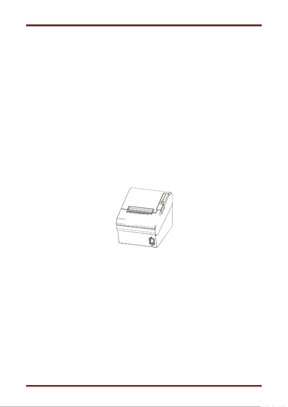
Desktop POS Printer
VLINE-80
User Manual
Page 2

CONTENTS
Statement
2. GETTING STARTED
5 Interfaces Signal
6 Troubleshooting
......................................................................................................................................................
1.1 Introductions
1.2 The Main Features
2.1 Packing List
2.2.1 VLINE80
2.2.2 VLINE80
3.1 Printer Specification
3.2.1 Continuous Thermal Paper Specification
3.3 Printing and Cutting Position
3.3.1 Printing Position
4.1 Unpacking
4.2 Installation Site and Direction of Printer
4.3 Power Adapter Connection
4.4 Interface Cable Connection
4.5 Cash Drawer Connection
4.6 Media Loading
4.6.1 Paper Confirmation
4.6.2 Procedure of Loading
4.7 Specification of LED Indication and Beeper
4.7.1 Specification of LED Indication
4.7.2 Beeper
4.7.3 Multi-color Status LED
4.8 Setting DIP switch
4.8.1 Serial interface(RS-232C)
4.8.2 Interfaces of parallel,USB,Bluetooth and Ethernet
4.8.3 Auto Cutter Enable/Disable Selection
4.9 Print Self Testing
4.10 Print Test
4.10.1 Print Self-Test
4.10.2 Printing Of Windows Driver Program
4.11 Bluetooth
5.1 USB
5.2 Cash Drawer
5.3 Power Port Definition
5.4 Other Optional Interface
6.1 Printer Not Working
6.2 LED Indicator On The Control Panel and Beeper Alarm
6.3 Troubles Occur During Printing
.................................................................................................................................................
5.4.1 Serial Interface
5.4.2 Parallel Interface
5.4.3 Ethernet Interface
...................................................................................................................................
..........................................................................................................................
.....................................................................................................................................
......................................................................................................................................
.........................................................................................................................
..................................................................................................................................
.......................................................................................................................
.......................................................................................................
................................................................................................................
......................................................................................................................................
....................................................................................
.........................................................................................................
.........................................................................................................
.............................................................................................................
..............................................................................................................................
..........................................................................................................
........................................................................................................
...............................................................................
........................................................................................
................................................................................................................................
......................................................................................................
.........................................................................................................................
..................................................................................................
...........................................................................................................................
.....................................................................................................................................
..................................................................................................................
....................................................................................................................................
.......................................................................................................................................
..................................................................................................................................
..................................................................................................................
.............................................................................................................
..................................................................................................................
...............................................................................................................
.............................................................................................................
.......................................................................................................................................
.....................................................................................................................
...................................................................................................
........................................................................
........................................................
.............................................................................
...........................................................................
............................................................
1
3
3
4
4
5
6
9
11
11
11
13
13
13
14
14
14
15
15
17
17
17
17
18
18
18
19
19
20
20
20
20
21
21
21
22
22
22
24
25
26
26
26
26
Page 3

6.4 Problems Emerge During The Paper Cutting Processes
6.5 Remove Jammed Paper
...............................................................................................................
............................................................
27
27
Page 4

2
Important Safety Instructions
1. Safety warning
1) Place the printer on a flat and stable surface.
2) Leave enough space around printer for operation and maintenance.
3) Do not insert anything into the ventilation slots or openings on the printer.
4) Do not place the printer on or near a heat source.
5) Do not use the printer near water. Never spill liquid into the printer.
6) Do not expose the printer to high temperatures, direct sunlight or dust.
7) Protect the printer from shock, impact and vibration.
8) Be certain the power source is within the voltage rating and frequency listed for the printer.
9) Switch off the printer power supply when won’t use it for a long time.
10) Do not place the power cord where it can be stepped on. If the power cord becomes
11) To ensure the print quality and reliability, you are suggested to use the recommended paper
12) Pls switch off the power supply when connect/disconnect all the ports or it will cause
13) Never carry out maintenance or repair work yourself. Always contact a qualified service
14) Keep this User Manual in a place which is easily accessible at all times.
Warnings: The print head will become very hot during printing; avoid contact with the print
head after printing has finished.
Warnings: Do not touch the printer head and connector in case static damage the printer
head.
2. Instructions
Carefully read the installation and operating instructions provided with the printer before starting
up your printer.
damaged or frayed, replace it immediately.
or the same quality paper.
damage to the printer control circuit.
technician.
Page 5

3
1 OVERVIEW
1) Patent design of unique vertical double auto cutter
2) Low noise
3) High print speed
4) Easy paper loading
5) Support page mode printing
6) Compatible with various width paper
7) Cash drawer interface
8) Communication interfaces optional
1.1 Introductions
VLINE80 is a thermal receipt printer with auto-cutter, featured by high print quality, high print
speed, high stability, etc. It can be used in commercial POS system, food industry and
occasions which need real-time field print receipts.
VLINE80 can connect with other equipment through parallel, serial, USB, Ethernet,
bluetooth, Wi-Fi and cash drawer interfaces. And the printer drivers are available for the
WINDOWS XP/WINDOWS 7/WINDOWS 8/Linux operating system.
1.2 The Main Features
Page 6
4
2. GETTING STARTED
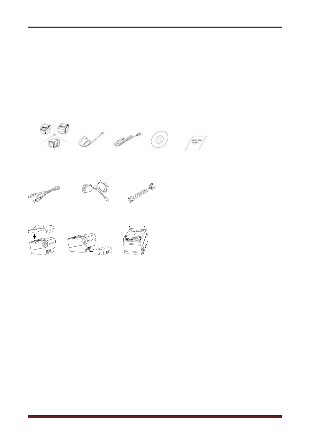
2.1 Packing List
1. Inspect the outside of both the box and the printer for possible damage.
2. Check whether you have received the following accessories together with the printer, if there is
Standard Accessories:
Optional Accessories:
1.The power cord and power adapter vary by local or region.
2.Some customers may require not packing some parts of the standard accessories for special, if
After receiving your printer, please check for possible shipping damage:
any items missing, please contact your local dealer.
Printer Power Adapter Power Cord CD Quick Start Guide
USB Cable Serial Cable Parallel Cable
Optional Accessories:
Note:
users are confused, please contact with your dealer for more detail.
Page 7
6
2.2.2 VLINE80-2
Page 8

8
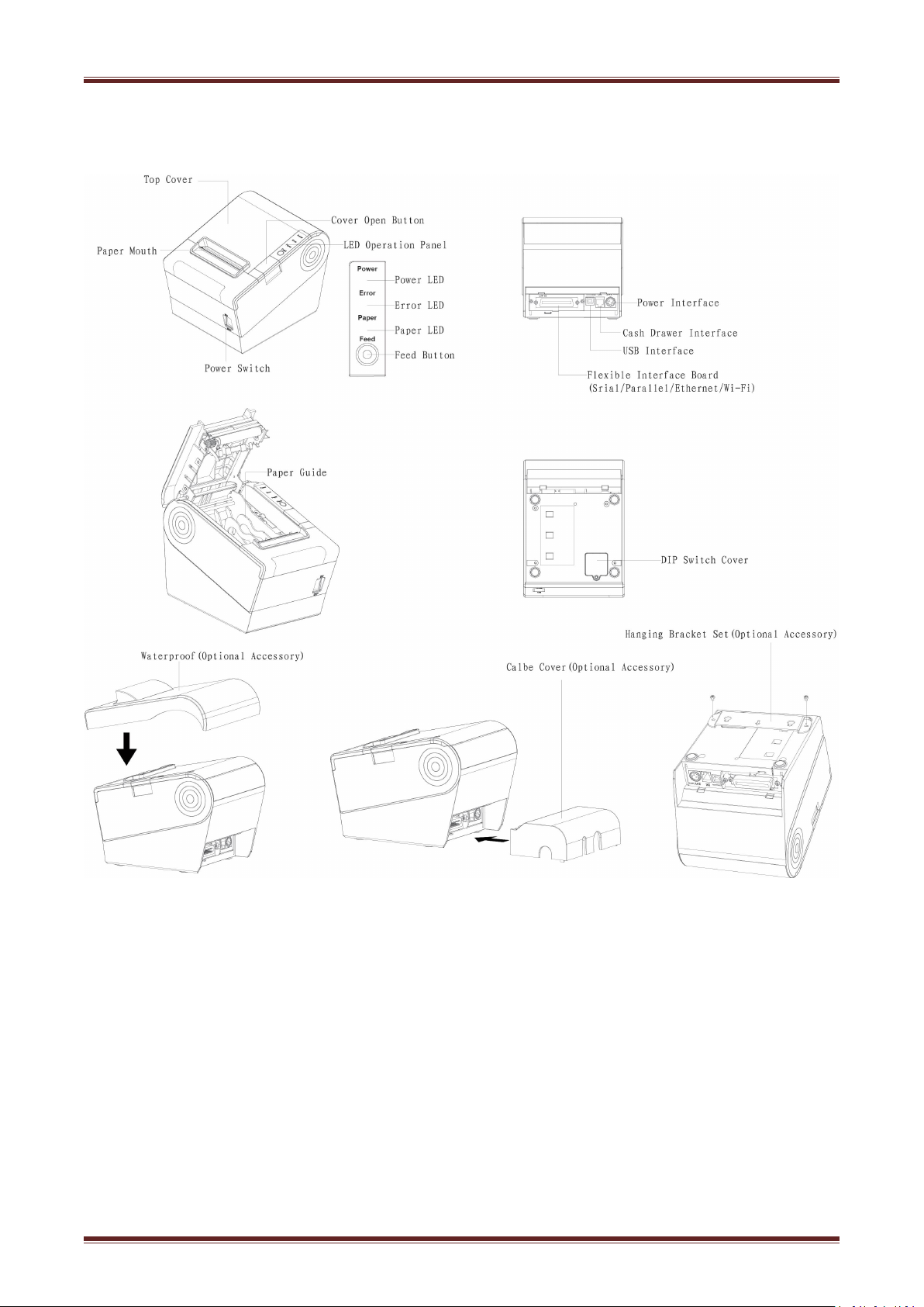
Specification of some part elements
1) Power switch
2) Feed Button
3) Power LED
4) Paper LED
5) Error LED
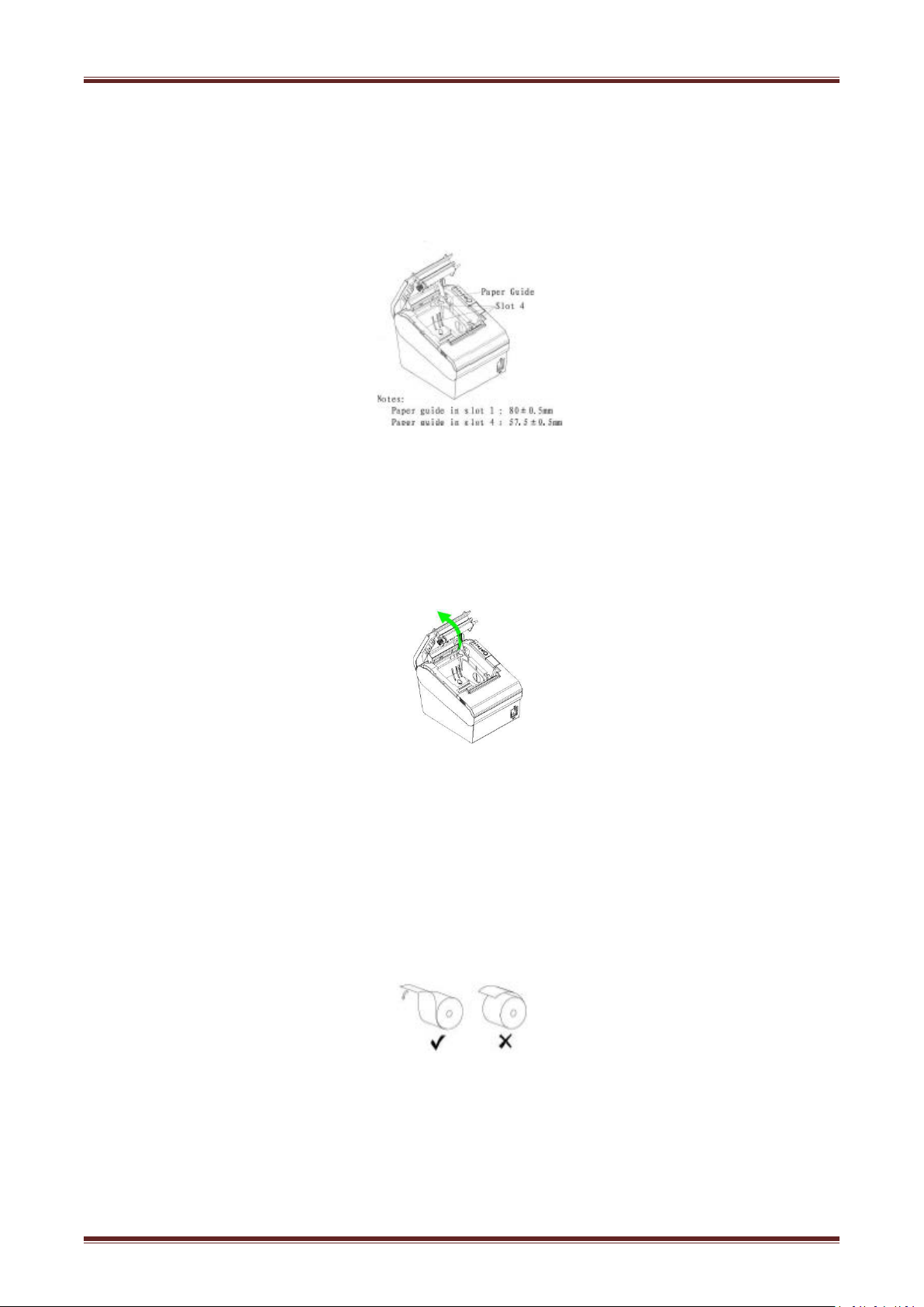
6) Paper guide
Press “0” to turn off power and press “1” to turn on power supply.
Feed paper:When it’s not in the alarm status,push the button to feed paper.Push the button
continuously to feed the long distance.
It indicate the power status.
It detect the status of paper,such as paper near end and paper end.See more details in”3.2
Specification of Indicated light and beeper”.
If there is abnormal phenomenon and error LED flashing,it means the printer is in the wrong
status.Please turn off the power immediately.
In paper storehouse,paper guide can change the position to adapt to different paper width.
①
VLINE80-2 storehouse has 4 paper guide slot.paper guide slot 1/4 adapt to
0
80
−+1
mm/ 58
+10
mm print
−
paper respectively.
Warnings:
Paper guide is essential to adjusting the paper width.Please keep it properly. And the paper guide
is un-taken during printing in case of print offset.
Page 9
9
3 Specification
Model
Printing
Print Method
Direct thermal line printing
Resolution
203dpi (8dots/mm)
Printing Width
48mm/72mm
Print Speed
Interface
Serial, Parallel, Ethernet, USB, Cash drawer, Bluetooth, Wi-Fi
Print Density
Adjustable from level 1 to level 4
Page Mode
support
Memory
RAM
16Mb
Flash
32Mb
Resident
Fonts
Chinese
GBK 16×16, 24×24dots
Alphanumeric
ASCII 9×17, 12×24dots
User-defined
Support
Code Page
47
Graphics
Support bitmap printing with different density and user defined bitmap
printing.
(Max size of each bitmap is 40K, the total size of bitmap is 256k)
Barcode
1D
UPC-A、UPC-E、EAN8、EAN13、CODE39、ITF、CODEBAR、CODE128、
CODE93
2D
PDF417、QR code
Detection
Sensors
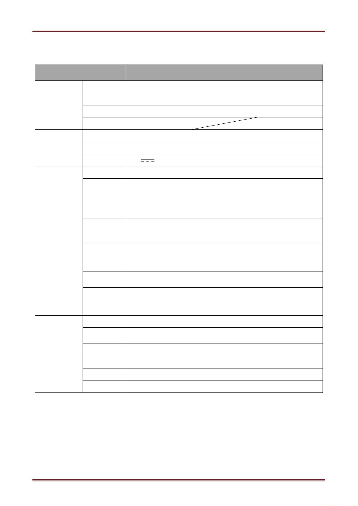
3.1 Printer Specification
Table 2-1 General Specification
(1/2)
VLINE80-2
200~250mm/s
Cover open, paper near end sensors
paper near end, black mark and cover open
sensors(optional)
Page 10
10
Table2-1 General Specification(Continued
Model
LED Indicator
Power LED
Green LED
Paper LED
Error LED
Status LED
Power Supply
Charging
External power adapter
Input
AC100V-240V 50-60HZ
Output
24V 2A
Paper
Paper Type
Thermal Receipt Paper
Paper Width
58mm/80mm
Paper
Thickness
0.050~0.090mm
Roll Paper
Diameter
Max. OD ф83mm
Paper Load
Paper Cut
Manual tear or Auto-cutter
Physical
Specification
Operating
Condition
0℃~40℃,20%~85%RH
Storage
Condition
-20℃~70℃,5%~95%RH
Dimensions
(L*W*H)
Weight
Reliability
TPH Lifetime
150km
Cutter
Lifetime
2,000,000 cuts
MTBF
360, 000 hours
Software
Emulation
ESC/POS
Driver
Windows XP/Vista/7/8/10/POSReady/Linux CUPS/OPOS/JavePOS
SDK
WinCE, Win Mobile, Android, iOS
VLINE80-2
Red LED
Red LED
)
(2/2)
Upward cover open and easy paper loading
195*147*147mm
1.8kg
Page 11
11
3.2 Media Specification
0
1
58
0
1
80
Paper Type
Manufacturer
FD210,PD150R,PD160R
OJI Paper CO.,LTD.
Pls. use the recommended thermal paper or same quality paper, otherwise it
Don’t stick the paper on the roll paper mandril;
If the thermal paper is polluted by chemical or oil, the thermal paper heat
Don’t use finger nail or hard articles to touch the surface of thermal paper,
When the environment temperature is higher than 70°C , the thermal paper
0
1 -
58
mm Print Paper
0
1 -
80
mm Print Paper
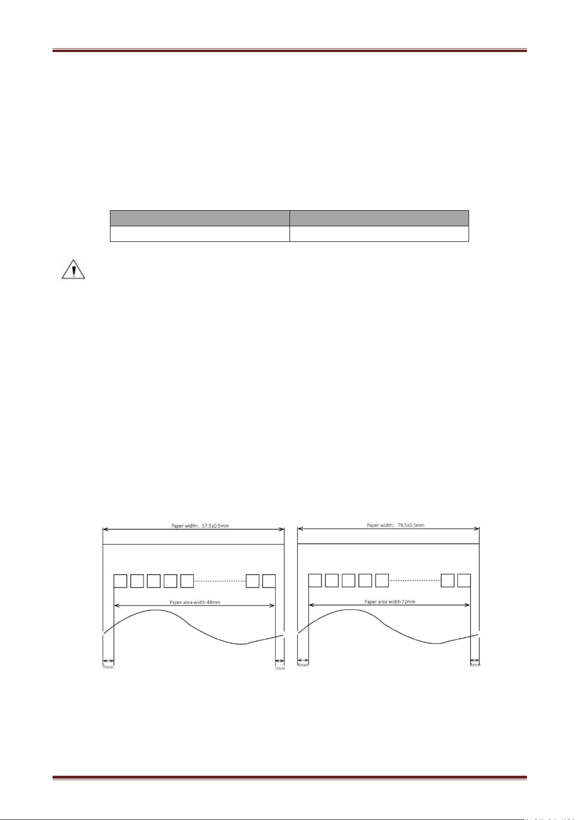
3.2.1 Continuous Thermal Paper Specification
Paper Type :Specified Thermal Paper
Paper Width :
Paper Outer Diameter :Max. 83 mm.
Roll Paper Core :13mm(Internal Diameter)
Paper Thickness :0.065 ~ 0.090mm
:
Notes
will influence the print quality and decrease the thermal printer head life;
sensibility decreases, which will influence the print quality;
mm/
mm
:18mm(Outer Diameter)
otherwise it will cause color fading;
color will fade, so pay attention to the influence of temperature, humidity and
sunlight.
3.3 Printing and Cutting Position
3.3.1 Printing Position
Page 12
12
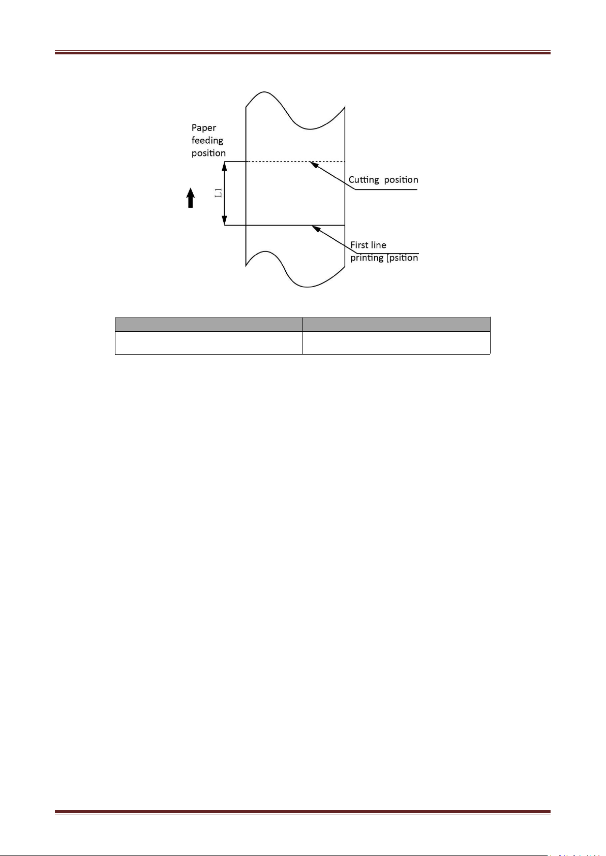
3.3.2 Cutting Position
Figure 3.3.2
Type
Paper Cutting Position(L1)
VLINE80-2
11.8mm
Page 13

13
4 Installation and Usage
1)
2) The printer should install at a flat and steady place. It’s recommend that install the printer
3) Keep printer far away from source of water
;
4) Avoid the printer on place where it is vibration and shock
5) Ensure printer ground connect is safe;
6) When the printer is at operation and maintenance, it is recommended to retain the enough
1) Make sure the printer's power switch is turned off;
2) Put the cable plug of power adapter facing up at flat side, insert the rear of the printer
3) Turn the power adapter input power;
4) Pay attention about disconnecting or connect the AC adapter at right method, or likely to
4.1 Unpacking
When open the package, check if any items are missing or damaged according to the packing list, if
so, contact the local dealer or manufacturer.
4.2 Installation Site and Direction of Printer
VLINE80-2 has two ways to install: wall-hanging(optional:wall-hanging carrier) and
horizontal installation. It’s recommend that install the printer at horizontal line.
at horizontal line.The angle of inclination should not exceed ± 10°(paper feed direction) if tilt
install printer, it does not allow to tilt by other direction.
space to ensure the printer can work in reliability and ease of operation.
4.3 Power Adapter Connection
power connector;
cause damage.
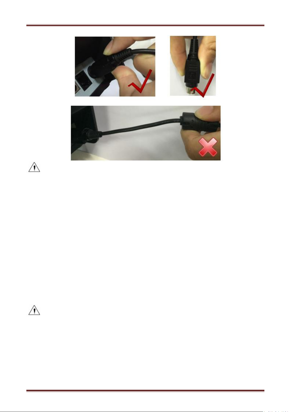
The plug of power adapter is designed in a switch type, when accessing power adapter and uttered
the voice "click", it means the connected socket switch is locked the adapter connect well,
otherwise please connect again .
When pull out the adapter, please pinch the shell of power adapter and pull the switch up, when
the switch is fully opened then pull out the power adapter.
Don’t put forth your strength to pull the plug by squeeze at any of place of power adapter. Because,
it is more difficult to pull it out and easy to damage the cable.
Page 14
14
Notes:
►
Please only use the power adapter are recommended by supplied or equivalent products;
►
When disconnecting the AC adapter plug, handheld plug connector housing, to avoid the pulling
on the cable in force;
►
Avoid drag the power adapter cable, otherwise it will damage the cables, causing fire and shock;
► Avoid put power adapter around a heating device, otherwise the cable may melt, causing fire
and shock;
► If you do not use the printer in a long time, disconnect the power supply of printer power
adapter.
4.4 Interface Cable Connection
1) Make sure the printer's power switch is turned off;
2) Put the interface cable into the matched interface and fixed with screws (or spring) on the plug;
3) Connect the other end of the interface cable to the host.
4.5 Cash Drawer Connection
1) Make sure the printer's power switch is turned off;
2) Connect the cash drawer cable into the cash drawer interface on the rear side of the printer.
Warning: Cash drawer interface can only be connected to a voltage of 24V cash drawer
device (can’t connect to the phone line, etc.)
4.6 Media Loading
Confirm the type of paper used by the printer before printing. The default paper type is specified
thermal paper.
Choose the paper guide according to the printing paper.
Page 15
15
4.6.1 Paper Confirmation
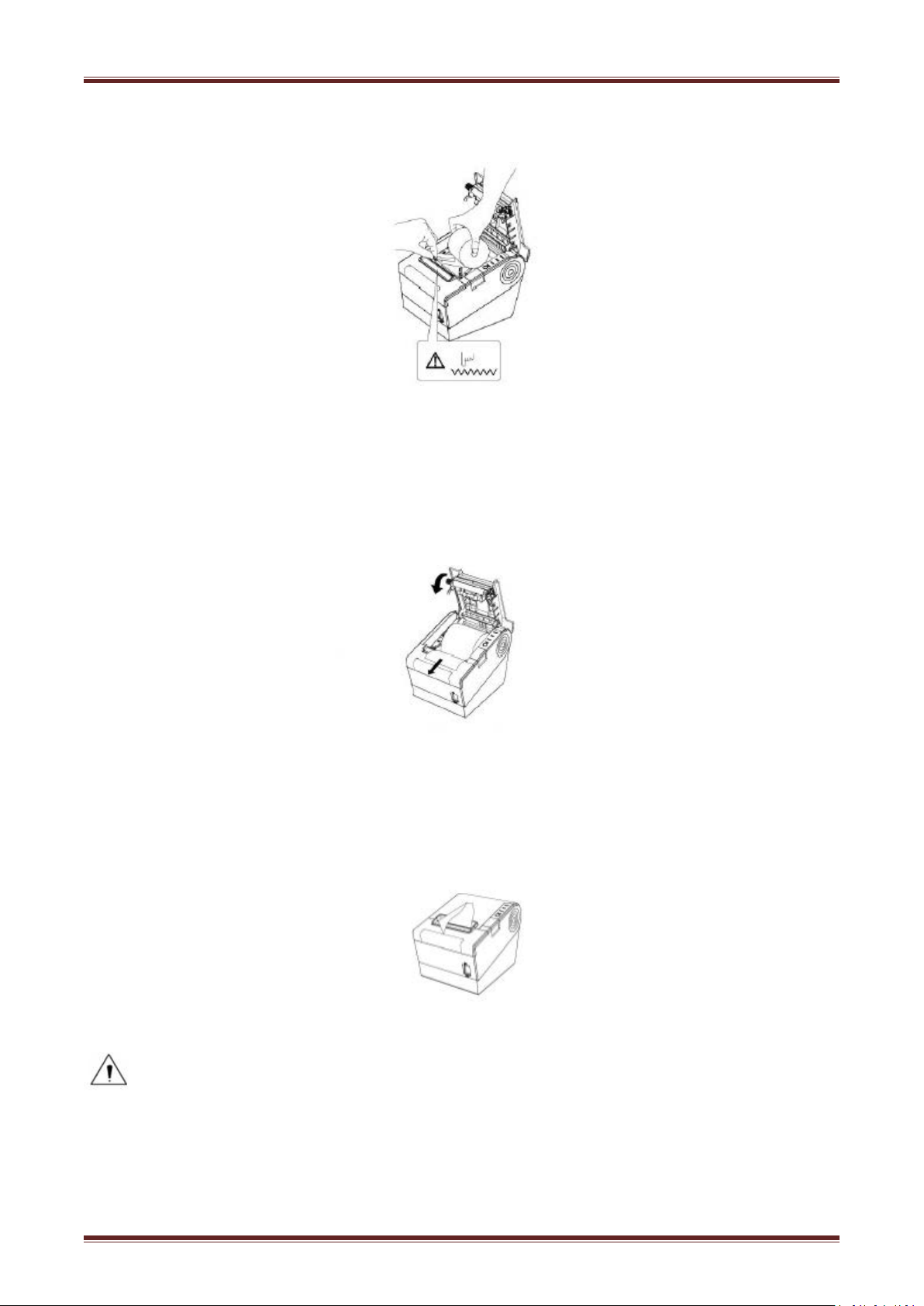
1) Turn off printer.
2)
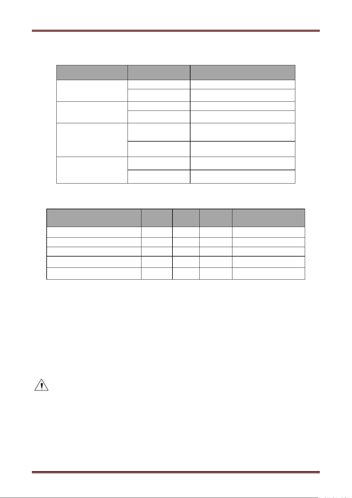
3) Put the paper into printer. Pay attention to the direction of the paper. (Like figure 4.6.2)
Method:
1)Put the finger into the hole in the paper guide, then lift the paper guide.
2)According to the paper width, insert the paper guide in the proper position.
4.6.2 Procedure of Loading
Pressing the open button, open the top cover of VLINE80-2. (Like
figure 4.5.1)
VLINE80-2
Figure 4.6.1
Page 16
16
4)
Close the top cover. (Like figure 4.6.3)
5) Tear the redundant paper. (Like figure 4.6.4)
Figure 4.6.2
Figure 4.6.3
Figure 4.6.4
:
Notes
► According to the paper size to adjust the paper guide;
► Make sure the paper inside is at tight status, or it will issue paper or other obstacle.
Page 17
17
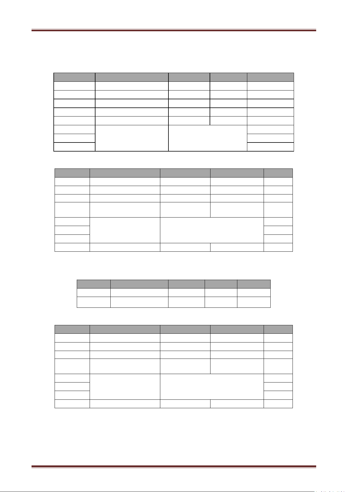
4.7 Specification of LED Indication and Beeper
Name
Status
Specification
POWER
LED
(Green)
ON
The printer work well
OFF
The printer powers off.
ERROR
LED
(Red)
Flash
The printer in an error state
OFF
The printer in an normal state
The printer in paper end state
OFF
The printer in an normal state
STATUS LED
Flash
The printer in an error state
ON
The printer in an normal state
Description
POWER
LED
ERROR
LED
PAPER
LED
Beeper
Cover Open
ONONON
“Beep ,Beep,Beep--”
Full of paper
ON
OFF
OFF
Silent
No Paper
ONONON
“Beep Beep Beep”.
Paper Near End
ON
OFF
ON
Silent
Cutter Jam
ON
Flash
OFF
”Beep—,Beep—”
4.7.1 Specification of LED Indication
4.7.2 Beeper
PAPER
(Red)
LED
ON
Notes:
The printer use a thermistor to detect the temperature of the print head. If the temperature of
print head is more than 65° C, printer will send a warning. If the temperature of print head is
more than 80° C, printer will stop working until the temperature is in the normal range.
Page 18
18
4.8 Setting DIP switch
Switches
Functions
ON
OFF
Default
1-1
Automatic line feed
Enable
Disable
OFF
1-2
Handshake
XON/XOFF
DTR/DSR
OFF
1-3
Bit length
7 bits
8 bits
OFF
1-4
Parity check
YesNoOFF
1-5
Parity selection
EVEN
ODD
OFF
1-6
Baud rate selection
(bps)
Reference form 1
OFF
1-7
ON
1-8
OFF
Switches
Functions
ON
OFF
Default
2-1
Chinese/English mode
English
Chinese
ON
2-2
Internal beeper control
Disable
Enable
OFF
2-3
Auto cutter
Disable
Enable
OFF
2-4
Busy conditions
Receive buffer
full
Printer off-line
Receive buffer full
OFF
2-5
Printer density
Reference form 2
OFF
2-6
OFF
2-7
OFF
2-8
Printing dots quantity
512
576
OFF
Switches
Function
ON
OFF
Default
1-1
Automatic line feed
Enable
Disable
OFF
1-2~1-8
Reserve
-
-
OFF
Switches
Functions
ON
OFF
Default
2-1
Chinese/English mode
English
Chinese
ON
2-2
Internal beeper control
Disable
Enable
OFF
2-3
Auto cutter
Disable
Enable
OFF
2-4
Busy conditions
Receive buffer
full
Printer off-line
Receive buffer full
OFF
2-5
Printer density
Reference form 2
OFF
2-6
OFF
2-7
OFF
2-8
Printing dots quantity
512
576
OFF
4.8.1 Serial interface(RS-232C)
DIP Switch 1
DIP Switch 2
4.8.2 Interfaces of parallel,USB,Bluetooth and Ethernet
DIP Switch 1
DIP Switch 2
Page 19
19
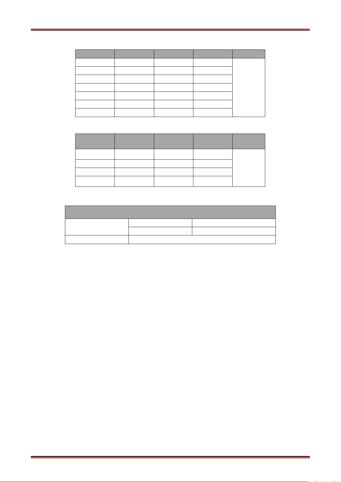
Form 1—Baud Rate Selection
Baud rate
1-6
1-7
1-8
Default
2400ONOFF
OFF
9600
4800ONOFF
ON
9600
OFFONOFF
19200
OFF
OFF
OFF
38400
OFFONON
57600
OFF
OFF
ON
115200
ONONON
2-5
2-6
2-7
Printer
density
Default
ON
ON
Reserve
1(diluted)
2
OFF
OFF
Reserve
2
ON
OFF
Reserve
3
OFF
ON
Reserve
4(dense)
DIP Switch setting 2
Switch2-3
ON
Auto cutter disable
OFF
Auto cutter enable
Application program
Ignore auto cutter error for continuous printing
1) Make sure the printer has been installed roll paper and turn off the top cover.
2) Make sure the printer has linked power.
3) Make sure the printer power off.
4) Press and hold FEED button,then turn on power switch, the printer will print out self-test page.
Form 2—Print Density Selection
4.8.3 Auto Cutter Enable/Disable Selection
4.9 Print Self Testing
Page 20

20
4.10 Print Test
1.Make sure the power switch is on;.
1. Install the Windows Driver program. (Please refer to the Windows Driver Manual)
2. Please set the “Interface” as the type you use.
3. Use the Windows Driver Program to print out the “Self-test page”.
1) Power on the printer.
2) Primary device search for outer Bluetooth devices.
3)
4)
5) Finish pairing.
4.10.1 Print Self-Test
The self-test checks the printer’s current settings, status and whether the printer has any problem.
2.Pressing the [Feed] button until the green LED indicator flash once. The printer is ready to receive
data as soon as it completes the self-test.
4.10.2 Printing of Windows Driver Program
4.11 Bluetooth
PDA with Bluetooth interface, laptop and other information terminals can drive the mobile thermal
printer VLINE80-2. Instructions as follows:
If there are some outer Bluetooth devices, choose “VLINE80-2”.
Connected to VLINE80-2.
Notes:
In pairing, the printer must be turned on.
when pairing, do not set many printers on, otherwise it can‘t figure out which one succeeds in
pairing.
Printer can only connect one primary device each time.After successful pairing,printer can’t be
connected with other primary device.If it need to connect other device,it should disconnect the
connection with the former primary device.
Page 21
21
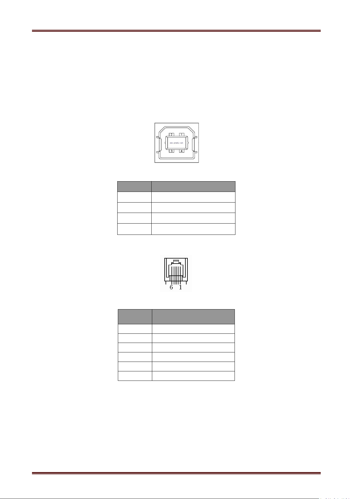
5 Interfaces Signal
PIN NO.
Signal Name
1
VBUS
2
D-
3
D+
4
GND
PIN NO.
Signal Name
1
FG
2
Drawer 1
3
DRSW
4
VDR
5
Drawer 2
6
GND
Driving voltage:DC 24 V
Driving current:maximum 0.8 A ( In 510 ms)
Drawer check signal
:
“L” = 0~0.5 V “H” = 3~5 V
Printer VLINE80-2 supports cash drawer interface and many other various communicate
interfaces, such as serial interface, parallel interface, USB interface, Ethernet interface bluetooth
interface, Wi-Fi interface. The printer has the communication board with the default USB interface
and cash drawer interface, and the other communication boards with the Ethernet interface,
parallel interface, RS232 interface are optional.
5.1 USB
Figure 5.1
5.2 Cash Drawer
Electrical characteristics
Figure 5.2
Page 22
22
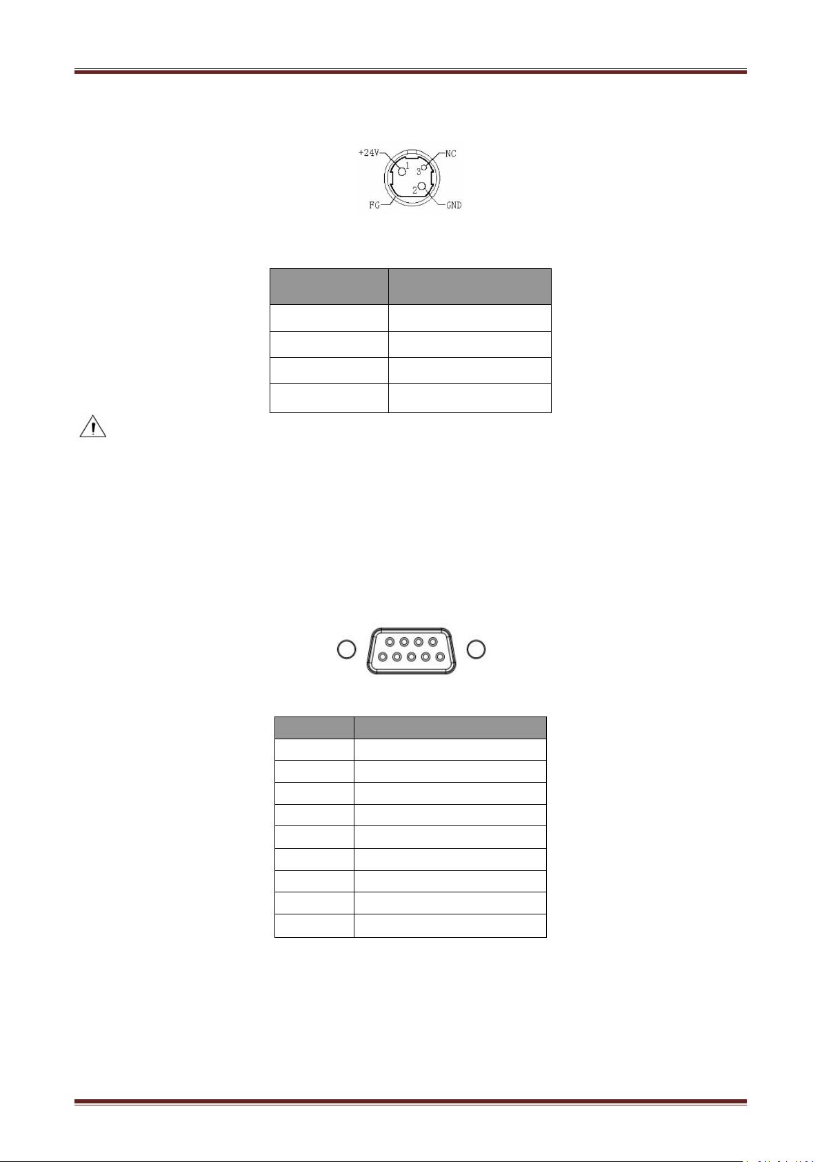
5.3 Power Port Definition
PIN NO.
Signal Name
1
+24V
2
GND
3
N.C
SHELL
F.G
Strictly prohibit unplug the cable while the printer is power on.
When arranging the line of communication, you have to avoid paralleling with the strong
you have to use the shielded communication line.
PIN NO.
Signal Name
1
-
2
TXD
3
RXD
4
-
5
GND
6
RTS
7
CTS
8
RTS
9
-
Note
:
current.
Figure 5.3
5.4 Other Optional Interface
5.4.1 Serial Interface
Printer VLINE80-2 serial interface is compatible with RS-232 standard, with 9 pin socket.
Figure 5.4.1 a
Page 23
23
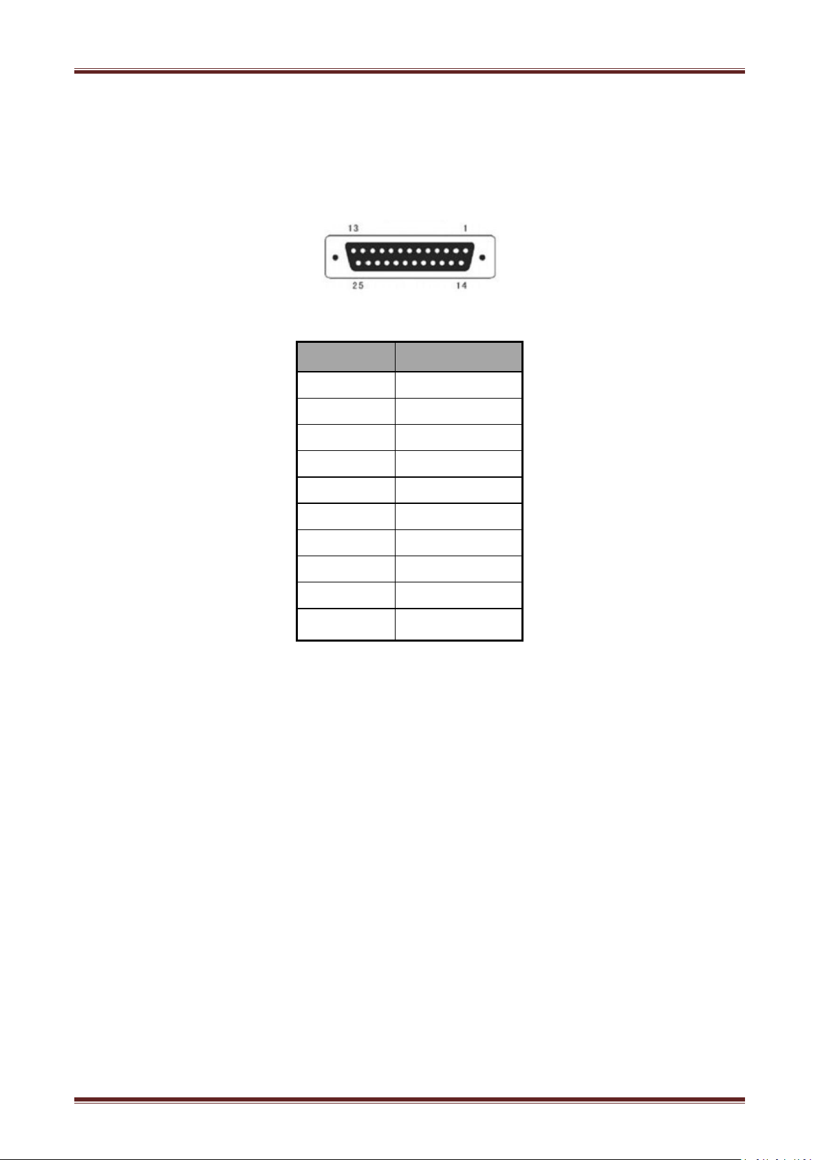
Printer VLINE80-2 serial interface are compatible with RS 232 standard, with 25pin socket. User can
PIN No.
Signal Definition
PIN1
Frame Ground
PIN2
TXD
PIN 3
RXD
PIN 4
RTS
PIN 5
Unconnected
PIN 6
DSR
PIN 7
GND
PIN 8~19
Unconnected
PIN 20
DTR
PIN 21~25
Unconnected
gain the setting of interface via printing configuration sample; the default setting of serial interface
is as follow, 9600bps(baud rates), 8 bit(data bit), 1 bit(stop bit), no parity, support RTS/CTS
handshaking protocol.
Figure 5.4.2 b
Page 24
24
5.4.2 Parallel Interface
Pin No.
Signal
Source
Signal Definition
1HData latch pulse, latch the data to the printer at the rising edge of the negative
2
H
Data 0(The lowest bit)
3
H
Data 1
4
H
Data
2
5
H
Data
3
6
H
Data
4
7
H
Data
5
8
H
Data
6
9
H
Data
7 (
The highest bit
)
10
P
Printer response signal, indicates that the printer has received the last byte of data;
A negative pulse of about 1us.
11
P
Busy Signal; The printer is busy; High level indicates that the printer can’t receive
12
P
PE Signal; paper end signal; High level indicates that the printer is paper end.
13
-
Unconnected
14
-
Unconnected
15
-
Unconnected
16
Logic Ground
17
Frame Ground, separated from logic ground
18
-
Unconnected
19~30
Logic Ground
31
-
Unconnected
32
P
Printer error signal, low level indicates that error occurs in the printer, the error
signal will output along with paper end signal.
33
Logic Ground
34~35
-
Unconnected
36
-
Unconnected
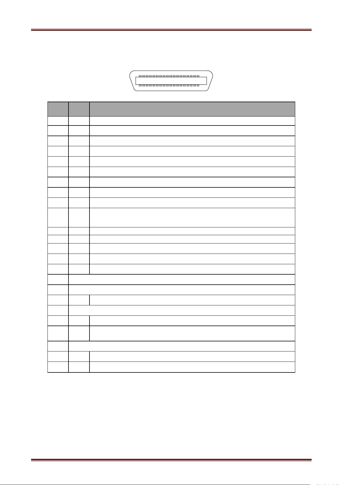
Parallel interface supports protocol with 36 pin CENTRONICS socket.
Figure 5.4.2
Note: H indicates that signal comes from Host computer, P indicates that signal comes from
Printer.
Page 25

25
5.4.3 Ethernet Interface
PIN NO.
Signal Name
1
TX+
2
TX-
3
RX+
4
-
5
-
6
RX+
7
-
8
-
Figure 5.4.3
Page 26
26
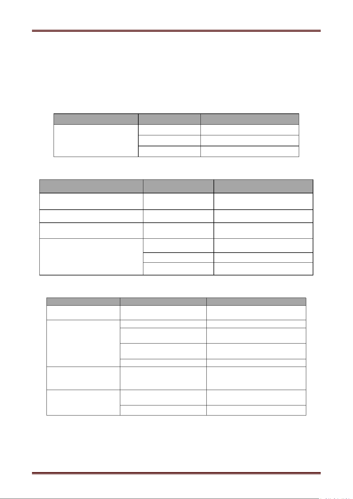
6 Troubleshooting
Problem description
Probable reason
Solution
LED not light, printer not
working
Printer No power
Connecting the power supply
Printer not on
Turn on the printer
Circuit board broken
Contact with the dealer
Problem description
Probable reason
Solution
Paper LED always on
Paper near end
The roll paper is near end, the printer
can work normally
Error LED always on and beeper alarms
Printer Cover open
Close the printer cover
Paper Error LED always on and beeper
alarms
Paper end
Reload the roll paper
Error LED blinks and beeper alarms
Thermal print head
overheated
Turn the printer off and resume when
it cools
overvoltage
Print with specified voltage
Low-voltage
Print with specified voltage
Problem description
Probable reason
Solution
Coloured stripe in the
paper
Paper near end
Reinstall the roll paper
Blurred printing or spot
Incorrect roll paper installation
Check if the roll paper is installed
Unqualified roll paper
Use recommended thermal roll
paper
Dirty thermal head or print
roller
Clean the thermal head or print
roller
Low print density
Increase the print density level
Paper Jam
Paper strike
Open the printer cover,check the
paper path and remove jammed
paper
Vertical print words
missing
Dirty thermal head or print
roller
Clean the thermal head or print
roller
Thermal head damaged
Contact your dealer for assistance
Your printer is very reliable, but occasionally problems may occur. This chapter provides
information on some common problems you may encounter and how to solve them. If you
encounter problems that you can not resolve, contact your dealer for assistance.
6.1 Printer Not Working
6.2 LED Indicator On The Control Panel and Beeper Alarm
6.3 Troubles Occur During Printing
Page 27
27
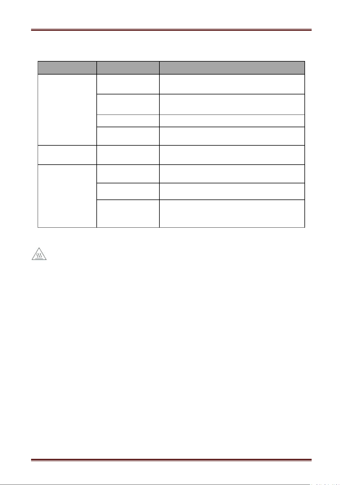
6.4 Problems Emerge During The Paper Cutting Processes
Problem description
Probable reason
Resolution
Cutter jam, the
movable cutter cannot
back
Cutter abrasion,
insufficient cutting
replace the cutter
Worm gear and worm
wheel abrasion
Replace the worm gear and worm wheel
Motor burnt
Replace the motor
Paper scraps
Clean the paper scraps on the transmission system
Insufficient cutting
Cutter edge abrasion,
paper too thick
Replace the cutter
Paper jam
Thermal printer head
over heat
Reduce the density of printing
Driving too fast
Reduce the printer speed to the limit of thermal printer
head
Wrong paper feeding
position
Put the paper parallel with the paper mount and insert
into the space between platen roller and the thermal
printer head
1)Turn off the printer and press open cover button.
2)Remove jammed paper, reinstall the roll, and close the cover.
6.5 Remove Jammed Paper
Warning: Do not touch the thermal print head because it becomes very hot after printing.
If the top cover can be opened,operate it according to the next steps.
If the auto cutter jam occurs on printer VLINE80-2 and you cannot open the printer cover, open
the cutter cover as shown on the left below.
1)Turn the printer off and open the front cover.
2)Turn the knob until cutter return to the normal position(tip tag).
Page 28

28
3)Close the front cover.
4)Open the top cover and remove jammed paper.
VLINE80-2
 Loading...