

Page 1

Ericsson W25
Fixed Wireless Terminal for WCDMA/HSPA Mobile Networks
Application Note:
Fax over IP with Ericsson W25
Page 2

Contents
1 INTRODUCTION .......................................................................3
1.1 BACKGROUND .............................................................................3
2 SYSTEM OVERVIEW................................................................4
2.1 THE FAX OVER IP SOLUTION.........................................................4
2.2 VOIP NETWORK...........................................................................5
2.2.1 SIP Server..................................................................................5
2.2.2 PSTN Gateway..........................................................................5
2.2.3 Session Border Controller (SBC)...............................................6
2.3 FAX CALL SETUP.........................................................................6
2.4 T.38 AND T30 PROTOCOL............................................................7
2.5 ACCESS NETWORK ......................................................................7
3 ERICSSON W25........................................................................8
3.1 SIGNALING...................................................................................8
3.1.1 Details over the SIP Implementation..........................................8
3.2 SECURITY....................................................................................8
3.3 MEDIA STREAM............................................................................8
3.3.1 Jitter Buffer.................................................................................8
3.3.2 Echo Canceller...........................................................................9
3.3.3 QoS............................................................................................9
3.4 INTEROPERABILITY.......................................................................9
4 W25 CONFIGURATION ..........................................................10
4.1 FAX SERVICE .............................................................................10
4.1.1 IMS User Agent........................................................................10
4.1.2 IMS Call Server........................................................................11
4.1.3 IMS Media Codec ....................................................................12
4.1.4 VoIP timer................................................................................14
5 REFERENCES ........................................................................15
6 ACRONYMS AND ABBREVIATIONS.....................................16
7 APPENDIX A...........................................................................17
2 2/221 02-FGB 101 327 Uen B – November 2007
Page 3

1 Introduction
This document gives a brief description of the Fax over IP and the
implementation in the Ericsson W25. It also includes a guidance of how to
configure the Ericsson W25.
1.1 Background
The Ericsson W25 is intended for residential and SOHO applications. The
focus for the Ericsson W25 is to enable both broadband data and voice
calls using existing 3G network. Additionally support for analog Fax
operation is essential when targeting business users such as SOHO users.
Fax support in GSM mobile networks is standardized, but not in 3G mobile
networks. The available options in 3G mobile networks are T.37, store and
forward mailbox, or T.38 Fax over IP. Since Fax communication is
considered legally binding when doing business, the demand on Fax
operation is that the sender of a Fax can get a receipt that the fax has been
delivered to the recipient in real-time. Therefore, Ericsson has chosen Fax
over IP (T.38) using packet switched connection in the Ericsson W25 to
enable Fax operation in 3G mobile networks. This, since it is the only option
that can guarantee that a fax has been delivered to the recipient in realtime. This can be done thanks to HS(D)PA introduced in 3G mobile
networks with features such as increased data bandwidth and reduced
delay.
2/221 02-FGB 101 327 Uen B – November 2007 3
Page 4
2 System Overview
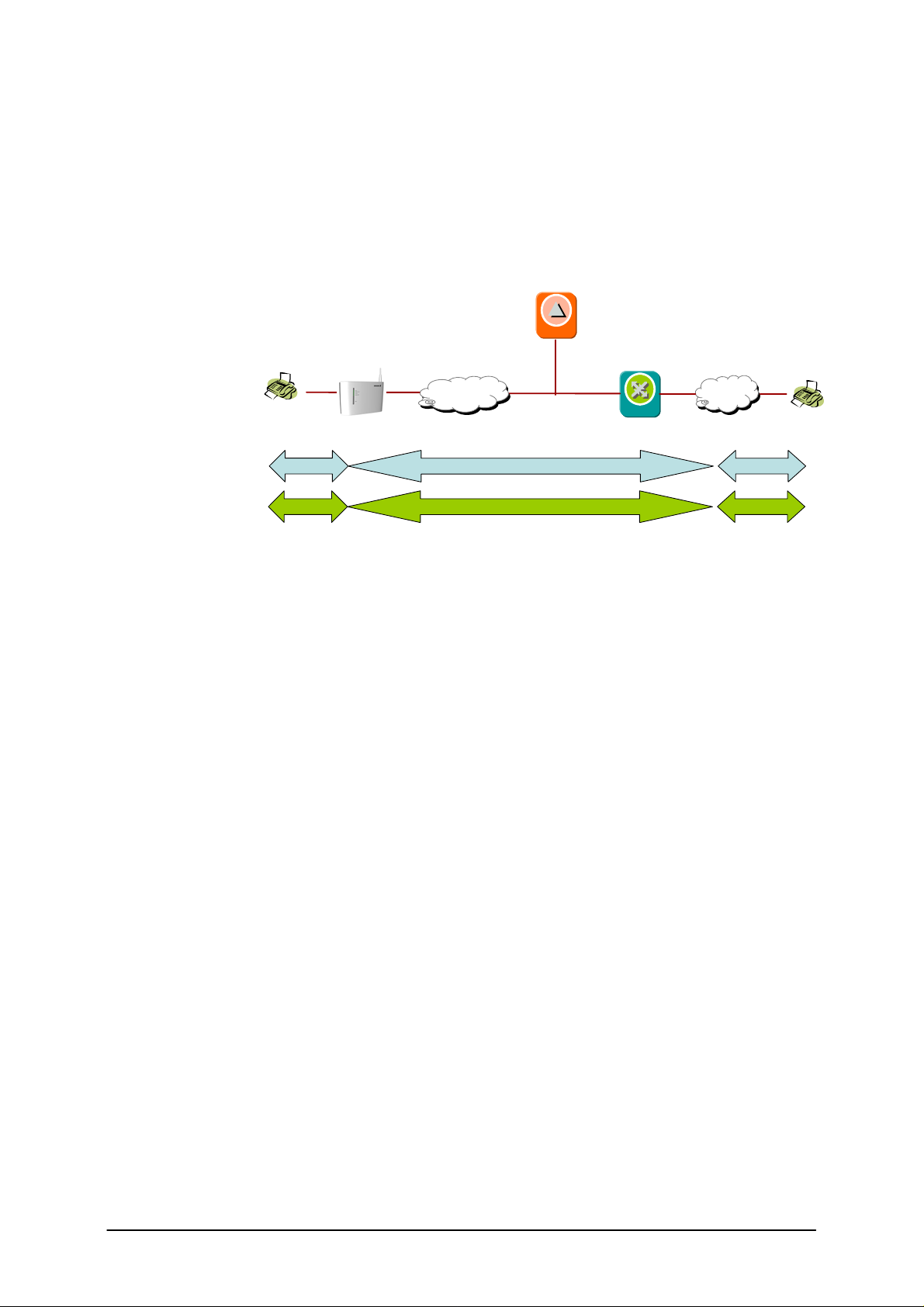
Fax over IP is based on Voice over IP. The Voice over IP system utilizes IP
technology over broadband networks and uses SIP for control signaling
and RTP for media. The differences between Fax and Voice are the
codecs. For voice the normal voice codecs are G.711, G.729, AMR etc, but
T.38 is used for fax. The voice and fax media are both sent in RTP packets.
W25
Access Network
SIP ServerSIP Server
PSTN Networks
Fax GWFax GW
Fax over IP
T.38
Figure 1 - Typical network for VoIP running Fax (T.38)
The fax machines still use the analog interface and the T.30 fax protocol. In
the picture above one fax is connected to the dedicated fax port on the
Ericsson W25 and the other fax to the PSTN.
The Ericsson W25 has a SIP User Agent associated to the fax port. The
User Agent registers in the SIP server. The User Agent originates and
terminates the FoIP (Fax over IP) calls and use the SIP protocol to manage
and control the media streams (T.38). T.38 enables real-time facsimile
communication over an IP network.
W25 does NOT support fax in clear channel i.e. G.711. This is not feasible
due to, primarily, lack of phase-synchronization between the endpoints. It
may be possible to transmit shorter fax messages but the method would
not be proven robust enough to be useful.
2.1 The Fax over IP solution
To enable a fax call a SIP server and PSTN gateway is required. There is
actually no need for extra features more than a basic call, i.e. no
supplementary services are required.
Analog lineAnalog line
T.30T.30
The SIP server needs to support SIP according to RFC 3261 and the Fax
gateway needs to support SIP and T.38. In addition to this the operator
might have requirements on charging etc, which is not taken into account in
this document. There are several products on the market which fulfill the
basic requirements.
4 2/221 02-FGB 101 327 Uen B – November 2007
Page 5
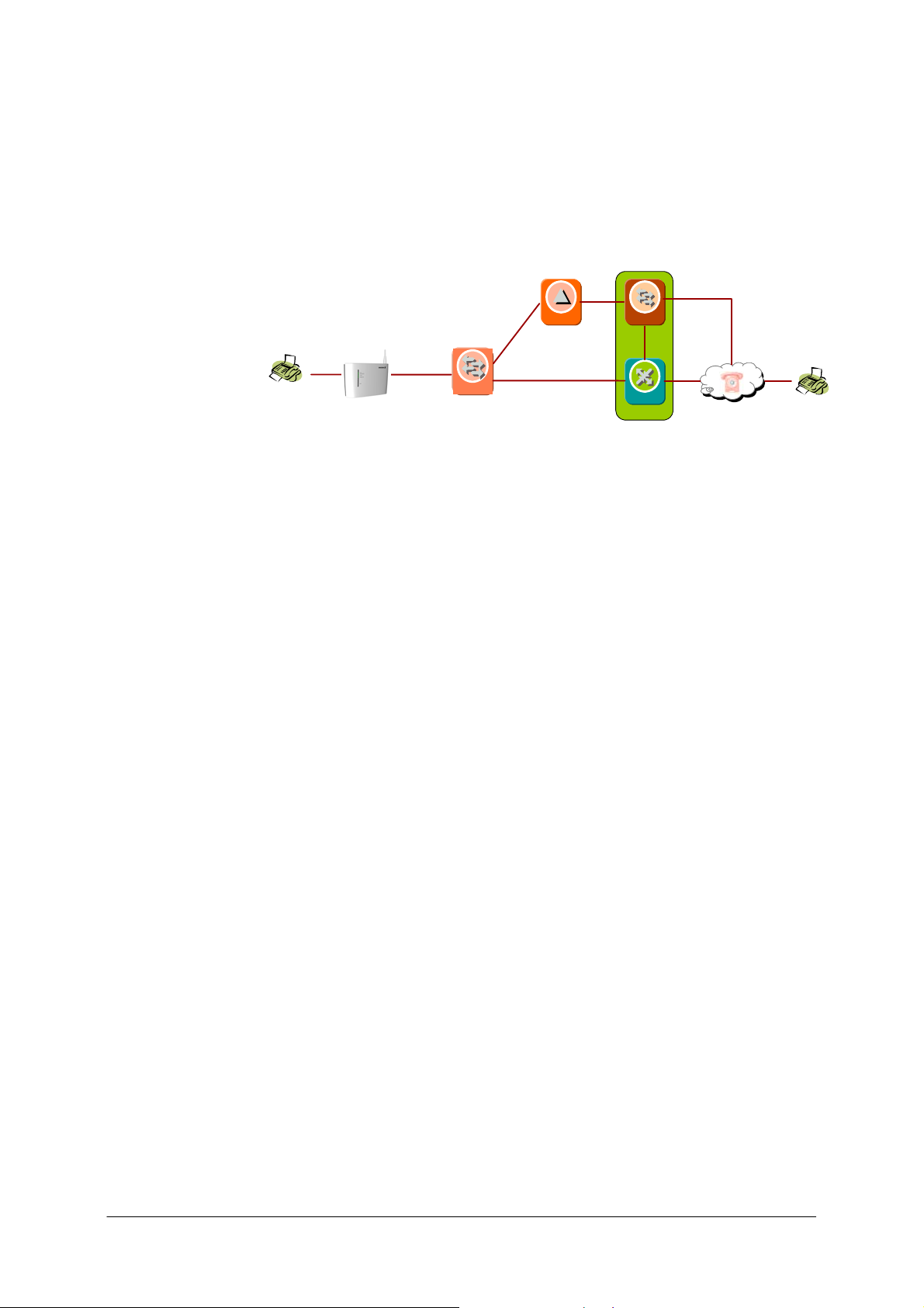
2.2 VoIP network
The basic building blocks for Voice and Fax over IP are a SIP server and a
PSTN gateway with T.38 support. Sometimes the PSTN gateway might
consist of two units; Media Controller and Media Gateway. Normally a
Session Border Controller (SBC) is used to handle security.
W25
2.2.1 SIP Server
The SIP server is the heart of VoIP system. It keeps track of the location of
each User Agent (UA). Calls are routed through the server. Each User
Agent has to authenticate to the server.
2.2.2 PSTN Gateway
The PSTN Gateway can be one single unit or divided in a Media Gateway
Controller (MGC), including the Signaling Gateway (for SS7/ISUP
connectivity), and the Media Gateway (MGW). Divided or not the
functionality is the same.
To be able to send fax between FWT and Fax machines on PSTN, each
User Agent in a FWT has an associated E.164 number in the PSTN. The
interworking between PSTN and VoIP is done in the PSTN gateway. Note
that the Fax E.164 number is separate from the E.164 number associated
with the SIM card in the FWT. So there is one E.164 number for fax and
another for voice.
SIP/RTP
SBCSBC
SIP
SIP ServerSIP Server
SIP
RTP
MGC-SGMGC-SG
MGWMGW
ISUP
TDM
PSTN Networks
2.2.2.1 Media Gateway Controller (MGC)
The Media Gateway Controller (MGC) provides interworking between the
SIP session control signaling and ISUP call control signaling to/from
external PSTN/PLMN networks. Furthermore, it controls the Media
Gateway resources.
The MGC normally provides the following capabilities:
• Handles multimedia session establishment, modification, and
termination using the SIP protocol in the IP Multimedia domain
and appropriate ISUP protocol in the circuit switched domain.
• Supports addressing and routing of multimedia sessions to and
from SIP server and interconnected PSTN nodes.
• Controls one or more Media Gateways.
• Performs mapping of application level signaling (SIP/ISUP).
2/221 02-FGB 101 327 Uen B – November 2007 5
Page 6
2.2.2.2 Media Gateway (MGW)
The Media Gateway (MGW) provides interworking between PSTN and IP
media streams, i.e. conversion between circuit-switched TDM (Time
Division Multiplexing) bearer circuits and packet-switched media streams
(RTP).
2.2.3 Session Border Controller (SBC)
The SBC can also be called outbound proxy, which normally is a SIP aware
proxy/stateful firewall. If an SBC is used in the network, the User Agent has
to be configured to use the SBC for all SIP sessions. Usually the SBC is
placed together with the firewall so the only way in to the SIP server is
through the SBC. An SBC can also overcome problems with NAT in the
network.
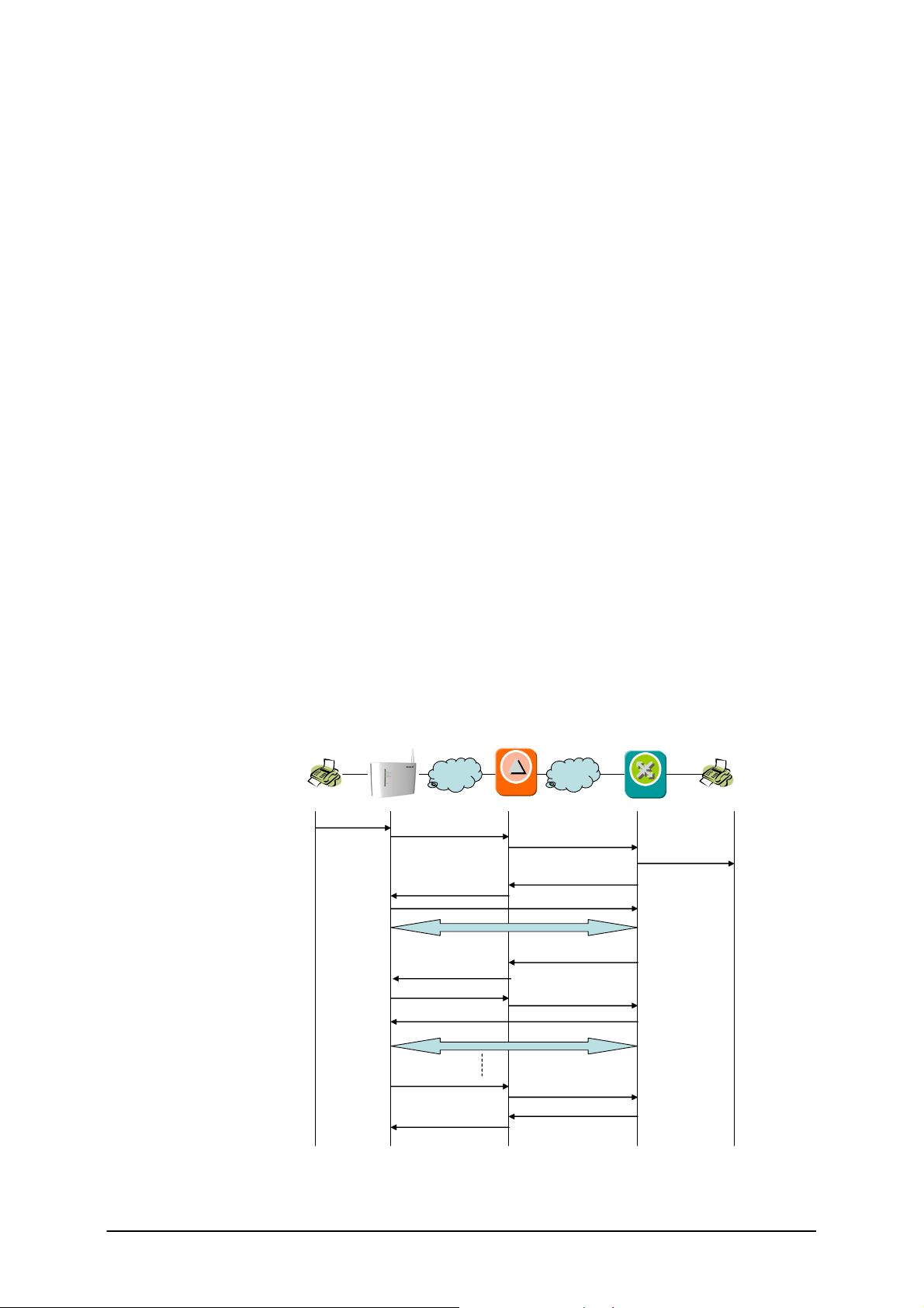
2.3 Fax Call Setup
The picture below shows the SIP signaling during a fax call.
When sending a fax from a fax-machine connected to the W25, the off-
hook status as well as the called number (B-subscriber)is detected by the
W25. This is included in a INVITE-message which is sent to the SIP server.
The SIP server forwards the INVITE to the appropriate fax gateway, which
then calls subscriber B on the PSTN. When the B subscriber answers, a
voice call is setup using the voice codec G.711. At the same time as the B
Fax answers, it starts sending out CED (called station identification) tones,
which is detected by the Fax gateway. Now the Fax gateway sends a reinvite to use T.38 protocol instead of voice codec G.711. The normal fax
training, e.g. negotiating fax transfer speed, is done using the T.38 protocol.
After the training, the pages are transferred and then the faxes go on-hook,
which then results in a SIP BYE message.
W25
Invite
200 OK
ACK
Re-Invite (T.38)
200 OK
ACK
IP
Fax GWFax GW
Ring signal
Detects off-hook
Fax tones
detected
Fax answer
Dialing
IP
SIP ServerSIP Server
Invite
200 OK
Audio (G.711)
Re-Invite (T.38)
200 OK
T.38
Fax call
completed
Detects
on-hook
Bye
200 OK
Bye
200 OK
6 2/221 02-FGB 101 327 Uen B – November 2007
Page 7

2.4 T.38 and T30 Protocol
There are two protocols used to transfer a fax over IP; T.30 [2] and T.38 [3].
T.30 is the protocol that describes the communication process between two
fax machines on a circuit-switched network.
T.38 is the protocol that describes the process for sending and receiving
fax in real-time over a packet network. The protocol makes adjustments for
delay, jitter, and dropped packets, which comes with the characteristics of
IP networks and radio networks. Since Fax devices are sensitive to timing it
would not be reliable to send and receive faxes over an IP network using a
normal voice codec e.g. G.711.
The gateway (MGW/MGC) receives T.30 data from the fax (PSTN-side),
converts the data to IP-packets, wraps it in T.38 packets, and sends it to
the destination, over the IP network.
The MGW/MGC works the other way round as well, receives the T.38 data
from the IP-network, un-wraps it to T.30-data, and converts and forwards it
to the PSTN-side.
Since T.30 data is encapsulated in T.38 packets, the same protocol used
for faxing over traditional circuit switched networks, remains for every IP fax
connection. Thus it’s important to have a high level of T.30 interoperability
to be able to communicate with legacy fax devices.
The normal bandwidth for the T.38 protocol is approx 30 kbps, but
depending on configuration it can be up to 80 kbps.
2.5 Access Network
The access network used for transmitting fax pages to and from the
Ericsson W25 is the WCDMA/HSDPA Radio access network and belonging
core network.
IP packets are sent in packet switch data channels over the radio network.
To increase the success rate of fax calls it’s important to have a connection
with as little as possible latency and jitter since, despite T.38, Fax devices
are sensitive to timing. WCDMA is a minimum requirement, but it’s
recommended to have a HSPA connection since this reduce the latency
and jitter. Future radio network improvements, mainly regarding QoS, the
fax transmission success rate will further improve.
2/221 02-FGB 101 327 Uen B – November 2007 7
Page 8

3 Ericsson W25
The Ericsson W25 will work as a gateway, using T.38 protocol. The fax
terminal shall be connected to the dedicated fax port on the Ericsson W25.
Associated to this fax port is a SIP User Agent, which manages and
controls the media streams by using the SIP protocol (RFC 3261) towards
the SIP server and the PSTN Gateway.
Depending on configuration, Fax calls between two FWT on the same radio
networks can be sent directly between the FWT’s not using the PSTN.
3.1 Signaling
The Ericsson W25 conforms to the SIP protocol according to RFC3261.
3.1.1 Details over the SIP Implementation
The Ericsson W25 supports:
• SDP according to RFC 2327.
• SDP usage according to RFC 3264.
• Media “hold” by using destination address 0.0.0.0
• Configuration of SIP message timers T1, T2 and B as defined in
RFC 3261.
• URI for fax calls, RFC 3966.
• PRACK method according to RFC 3262.
• Session timer, RFC 4028.
3.2 Security
The Ericsson W25 authenticates towards the VoIP system using the HTTP
Digest Authentication mechanism.
3.3 Media Stream
Due to the procedure of setting up a fax call both G.711 and T.38 is
supported by the Ericsson W25. The W25 requires that the call is first setup
as a normal voice connection (using G.711) before a switchover from voice
to T.38 fax is done with SIP Re-INVITE practices.
3.3.1 Jitter Buffer
One important function in the Ericsson W25 is the jitter buffer, which is
necessary to have due to the latency and jitter in the IP network. The
access network contributes with most of the latency and jitter, so to reduce
this a HSPA connection is recommended.
8 2/221 02-FGB 101 327 Uen B – November 2007
Page 9

3.3.2 Echo Canceller
To improve the fax transfer the Ericsson W25 also has an echo canceller in
accordance with G.168.
3.3.3 QoS
The outgoing VoIP related traffic will be prioritized before other traffic from
the Ericsson W25 to reduce the uplink delay and jitter.
3.4 Interoperability
The Ericsson W25 is interoperable with e.g. Broadsoft, which is included in
Ericsson’s IMT (IMS Multimedia Telephony). Other SIP servers and Fax
gateways should also work as long as they support SIP v2 (RFC 3261) and
T.38, but interoperability testing needs to be done to verify this.
For more information on Ericsson’s IMT see ref [1].
2/221 02-FGB 101 327 Uen B – November 2007 9
Page 10

4 W25 Configuration
For configuration purpose, the Ericsson W25 includes a CLI (Command
Line Interface) and a WUI (web user interface) which are accessible as
illustrated in the figure below.
IP
Please also see the document “Ericsson W25 Administrator’s Guide” for
more details on Ericsson W25 configuration.
4.1 Fax service
To configure the Fax service in the W25 the CLI is used. It can either be
done remotely via SSH or via telnet locally with operator or root user
access.
Normally two parts need to be configured in the W25:
• IMS User Agent (the local client credential)
• IMS Call server (remote SIP server(s))
In addition to this it also might be needed to fine tune the T.38 codec
depending on the remote fax gateway. This is done in “IMS media codec”.
4.1.1 IMS User Agent
The IMS (SIP) User Agent is associated to the fax port on the Ericsson
W25. This integrated User Agent controls the VoIP sessions and manages
and controls the media streams by using the SIP protocol towards the SIP
Server and Media Gateway.
To configure the User Agent you need:
• authentication id, which is used for authentication and is usually the
same as user id, but sometimes with domain name e.g.
xxxxx@domainname.com
10 2/221 02-FGB 101 327 Uen B – November 2007
Page 11

• user id , which is the public user identification e.g. the phone
number xxxxx
• password, which is the password for the user id
4.1.1.1 CLI commands
The W25 has already one User Agent configured by default, so this needs
to be modified. The commands to modify are:
cf set ims.user_agent[0].auth_id <auth_id>
cf set ims.user_agent[0].user_id <user_id>
cf set ims.user_agent[0].user_password <password>
The command to save the new configuration is:
cf commit
To display the entries in the user account list, use the following command:
cf show ims.user_agent
ims.user_agent[0].auth_id "user.grp"
.user_id "54321"
.user_password "mysecret"
.ims_callserver_index 1
The last parameter “ims_callserver_index” is referring to the configuration
of IMS Call Server, which will be described below. Normally you do not
need to change this.
4.1.2 IMS Call Server
Here you configure the IMS/SIP server(s) address (IP or FQDN), and
possibly an outbound proxy.
The SIP-server address configuration is mandatory while the outbound
proxy is optional, depending on network configuration.
The outbound proxy is usually an SBC (Session Border Controller) e.g. IMS
P-CFCS
4.1.2.1 CLI commands
The W25 has already one IMS Call Server defined with default values, but
the SIP proxy and outbound proxy addresses (IP or FQDN) need to be
modified. The commands for this are:
cf set ims.callserver.proxy[0].address <sip proxy>
cf set ims.callserver.outbound_proxy <outbound proxy>
The command to save the new configuration is:
cf commit
2/221 02-FGB 101 327 Uen B – November 2007 11
Page 12

Note if the proxy[x].address is set to “localhost”, the W25 will not register to
any SIP server.
To display the entries in the call server, use the following command
cf show ims.callserver
ims.callserver[0].domain "server.com"
.proxy[0].address "host.server.com"
.port 5060
.outbound_proxy ""
.local_ip_interface "ppp0"
The domain parameter is for future use. The proxy[x].port is by default 5060
(according to the SIP standard). The port number only needs to be
changed in special case.
In a normal scenario the SIP server is accessible via the WAN interface,
but for test and demo purposes it’s possible to use a SIP server which is
connected on the LAN interface. To change this you need to modify
“local_ip_interface” from “ppp0” (WAN) to “br0” (LAN).
4.1.3 IMS Media Codec
The IMS Media Codec commands configure the settings for T.38.
4.1.3.1 T.38 Settings
The settings for T.38 are used for Fax. The following parameters can be
configured:
Table 1 T.38 configuration parameters
Parameter Description
forward_error_
correction
max_bit_rate
local_tcf
fill_bit_
removal
Specifies if FEC (Forward Error Detection) should
be used or otherwise Redundancy packets will be
used. (True|False)
The max bit rate for fax transmission. Valid values
are 2400, 4800, 7200, 9600, 12000 and 14400.
Defines whether the tcf (Training Check Flag)
should be local i.e. only between the fax machine
and the W25 T.30-client or end to end (to the
terminating fax machine). If using UDP (default)
this parameter should be set to false. (True|False)
Capability to remove and insert fill bits in Phase C,
non-ECM data to reduce bandwidth in the packet
network. (True|False)
transcoding_mmr
Specifies whether the ability to convert to/from
MMR from/to the line format for increasing the
compression of the data and saving bandwidth in
the packet network. (True|False)
transcoding_
12 2/221 02-FGB 101 327 Uen B – November 2007
Specifies whether the ability to convert to/from
Page 13

Parameter Description
jbig
JBIG should be used, (reduces bandwidth).
(True|False)
Ecm
extended_
roundtrip
data_wait_time
low_rate_
recovery_
packets
high_rate_
recovery_
packets
Specifies if ECM should be used or not.
(True|False)
Enables the support of dealing with extended
round trip delays (True|False)
This parameter indicates the time for internal
buffering appropriate V.21, ECM and non-ECM
page data in the case if the end of line or the end
of the HDLC frame is not detected. The value
range is from 0 up to 100. The default value is to
set to 50 which is of 500 ms buffering. One unit is
of 10 ms. After the Data Wait Time T.38 starts with
the modulation also if not all data is received
This parameter is used for the Redundancy and
the FEC error Correction Mode on a UDP
transmission for V.21. The parameter indicates the
number of additional recovery data packets send
during a low rate Fax transmission (control data).
The value can be between 0 and 4.
This parameter is used for the Redundancy and
the FEC error Correction Mode on a UDP
transmission for V.17, V.29, and V.27. The
parameter indicates the number of additional
recovery data packets send during a high rate Fax
transmission (image data). The value can be
between 0 and 4.
To show the current configuration for T.38, use the following command:
cf show ims.media.codec.t38
ims.media.codec.t38.forward_error_correction false
.max_bit_rate 14400
.local_tcf false
.fill_bit_removal false
.transcoding_mmr false
.transcoding_jbig false
.ecm true
.extended_roundtrip false
.data_wait_time 500
.low_rate_recovery_packets 4
.high_rate_recovery_packets 1
Depending on radio network characteristics, there might be a need for fine
tuning T.38.
ECM (Error Correction Mode) may need to be reconfigured since ECM is
sensitive for packet loss, it might be necessary to disable this.
2/221 02-FGB 101 327 Uen B – November 2007 13
Page 14

It’s recommended to not enable “extended_roundtrip”, since it has been
shown that this cause interoperability problems.
Not all gateways support recovery packets, but then the recovery packets
will be ignored. Note that at the same time as the recovery_packets is
increase, the bandwidth requirement increase as well. For more details see
[3].
4.1.4 VoIP timer
To avoid that the fax port is used as a telephony port using Voice over IP, it
is possible to restrict for how long a voice call is allowed. If no fax tones are
detected i.e. switching over to T.38, within a certain time the call is closed
by the W25. The time is configurable and default value is 60000 ms (60s). If
configured to “0”, the timer will never expire, i.e. the call will not be closed
by the FWT. The parameter name is:
telephony. pots.line_interface[0].voip_session_timeout 60000
14 2/221 02-FGB 101 327 Uen B – November 2007
Page 15

5 References
[1] Internal System Description IMT (IMS Multimedia Telephony)
3.01551-HSC 113 03/4 Uen
[2] T.30 Procedures for document facsimile transmission in the
general switched telephone network
[3] T.38 Procedures for real-time Group 3 facsimile communication
over IP networks
2/221 02-FGB 101 327 Uen B – November 2007 15
Page 16

6 Acronyms and Abbreviations
CDMA
Code Division Multiple Access
CLI
Command Line Interface
DNS
Domain Name System
E.164
International Public Telecommunication
Numbering Plan as described in the ITU-T
Recommendation E.164.
FoIP
Fax over IP
FWT
Fixed Wireless Terminal
GSM
Global System for Mobile Communication
HSDPA
High Speed Downlink Packet Access
HSPA
High Speed Packet Access
HTTP
Hypertext Transfer Protocol
IMT
IMS Multimedia Telephony
IP
Internet Protocol
ISUP
ISDN User Part
LAN
Local Area Network
MGC
Media Gateway Controller
MGW
Media Gateway
PDP
Packet Data Protocol
PLMN
Public Land Mobile Network
POTS
Plain Old Telephone Service
PSTN
Public Switched Telephony Network
QoS
Quality of Service
RAB
Radio Access Bearer
RAN
Radio Access Network
RFC
Request for Comments
RTP
Real-Time Transfer Protocol
SDP
Session Description Protocol
SFQ
Stochastic Fair Queuing
SIP
Session Initiation Protocol
SOHO
Small Office Home Office
SSH
Secure Shell
TDM
Time Division Multiplexing
UA
User Agent
URI
Uniform Resource Identifier
VoIP
Voice over IP
WCDMA
Wideband CDMA
WLAN
Wireless LAN
WUI
Web User Interface
16 2/221 02-FGB 101 327 Uen B – November 2007
Page 17

7 Appendix A
This chapter describes the test results for the End-to-End T.38 interoperability tests
that has been performed on the T.38 implemented in W25. The list includes all
successful fax machines
(The list has the following format: Fax machine, Profile and Speed)
AT/T PPF200 MMR, ECM, 200x100 V.29 9600
Brother 6650MC MMR, ECM, 200x100 V.17 14400
Brother 7150C MMR, ECM, 200x100 V.17 14400
Brother MFC 4600 MMR, ECM, 200x100 V.17 14400
Brother MFC 4650 MMR, ECM, 200x100 V.17 14400
Brother MFC 4550 MMR, ECM, 200x100 V.17 14400
Canon Fax B340 MMR, ECM, 200x100 V.17 14400
Canon Fax TF 301 MMR, ECM, 200x100 V.29 96001
Canon L 777 MMR, ECM, 200x100 V.17 14400
Canon Multi Pass C2500 MMR, ECM, 200x100 V.17 14400
Canon Multi Pass C530 MMR, ECM, 200x100 V.17 14400
Canon Multi Pass C545 MMR, ECM, 200x100 V.17 14400
Canon Multi Pass C555 MMR, ECM, 200x100 V.17 14400
Canon Multi pass C560 MMR, ECM, 200x100 V.17 14400
Canon Multi Pass C755 MMR, ECM, 200x100 V.17 14400
Canon Multi Pass L6000 MMR, ECM, 200x100 V.17 14400
Hewlett Packard Fax 920 MMR, ECM, 200x100 V.17 14400
Hewlett Packard Fax 200 MMR, ECM, 200x100 V.29 9600
Hewlett Packard Laser Jet 3200 MMR, ECM, 200x100 V.17 14400
Hewlett Packard Office Jet MMR, ECM, 200x100 V.29 9600
Hewlett Packard Office Jet 350 MMR, ECM, 200x100 V.29 9600
Hewlett Packard Office Jet 570 MMR, ECM, 200x100 V.17 14400
Lumina 2096 MMR, ECM, 200x100 V.29 9600
Mita LDC 750 MMR, ECM, 200x100 V.17 14400
Monroe MX 4020 MMR, ECM, 200x100 V.29 9600
Muratec F150 MMR, ECM, 200x100 V.17 14400
Muratec F 56 MMR, ECM, 200x100 V.17 14400
Muratec F 90 MMR, ECM, 200x100 V.17 14400
NEC Nefax 480 MMR, ECM, 200x100 V.17 14400
Okidata Okifax 1000 MMR, ECM, 200x100 V.29 9600
Okidata Okifax 2200 MMR, ECM, 200x100 V.29 9600
Okidata OkiOffice 84 MMR, ECM, 200x100 V.17 14400
Panasonic PX 350 MMR, ECM, 200x100 V.29 9600
Panasonic PX 5 MMR, ECM, 200x100 V.29 9600
Panasonic UF 880 MMR, ECM, 200x100 V.17 14400
Panasonic UF V60 MMR, ECM, 200x100 V.29 9600
Ricoh 180 MMR, ECM, 200x100 V.29 9600
Ricoh 3500L MMR, ECM, 200x100 V.17 14400
Ricoh Fax 240 MMR, ECM, 200x100 V.29 9600
Ricoh Fax 3000L MMR, ECM, 200x100 V.29 9600
Sharp FO 5400 MMR, ECM, 200x100 V.17 14400
Sharp UX 1400 MMR, ECM, 200x100 V.17 14400
Sharp UX 3600M MMR, ECM, 200x100 V.17 14400
Toshiba TF 421 MMR, ECM, 200x100 V.29 9600
Toshiba TF 671 MMR, ECM, 200x100 V.17 14400
US Robotics 33.6 Mdl 1172 MMR, ECM, 200x100 V.29 9600
Xerox 3004 MMR, ECM, 200x100 V.17 14400
Xerox 7033 MMR, ECM, 200x100 V.17 14400
Xerox Work Center 250 MMR, ECM, 200x100 V.29 9600
Xerox Work Center 470cx MMR, ECM, 200x100 V.17 14400
Xerox Work Center 480cx MMR, ECM, 200x100 V.17 14400
Xerox Work Center XK50cx MMR, ECM, 200x100 V.17 14400
3 COM EtherLink III LAN 33.6 MH, ECM, 200x100 V.17 14400
AT/T9015PF MH, Non-ECM, 200x100 V.29 9600
AT/T Data Port MH, Non-ECM, 200x100 V.17 14400
AT/T PPF200 MH, ECM, 200x100 V.29 9600
Boca MV34E MH, Non-ECM, 200x100 V.17 14400
Brother 6650MC MH, ECM, 200x100 V.17 14400
Brother 7150C MH, ECM, 200x100 V.17 14400
Brother Fax 190 MH, Non-ECM, 200x100 V.29 9600
Brother Fax 580 MC MH, ECM, 200x100 V.17 14400
Brother Intellifax 2500 MH, Non-ECM, 200x100 V.29 9600
Brother Intellifax 600 MH, Non-ECM, 200x100 V.29 9600
Brother Intellifax 625 MH, Non-ECM, 200x100 V.29 9600
Brother Intellifax 950M MH, Non-ECM, 200x100 V.29 9600
Brother MFC 4600 MH, ECM, 200x100 V.17 14400
Brother MFC 4650 MH, ECM, 200x100 V.17 14400
Brother MFC 4550 MH, ECM, 200x100 V.17 14400
Canon B70 MH, Non-ECM, 200x100 V.29 9600
Canon Fax 750 MH, ECM, 200x100 V.29 9600
Canon Fax B340 MH, ECM, 200x100 V.29 9600
Canon Fax TF 301 MH, ECM, 200x100 V.29 9600
Canon L777 MH, ECM, 200x100 V.17 14400
Canon Multi Pass C2500 MH, ECM, 200x100 V.17 14400
Canon Multi Pass C530 MH, ECM, 200x100 V.17 14400
Canon Multi Pass C545 MH, ECM, 200x100 V.17 14400
Canon Multi Pass C5500 MH, ECM, 200x100 V.17 14400
Canon Multi Pass C555 MH, ECM, 200x100 V.17 14400
Canon Multi Pass C560 MH, ECM, 200x100 V.17 14400
Canon Multi Pass C755 MH, ECM, 200x100 V.17 14400
Canon Multi Pass L6000 MH, ECM, 200x100 V.17 14400
Cardinal MH, ECM, 200x100 V.17 14400
Compaq 9600 PCMCIA MH, ECM, 200x100 V.29 9600
Eiger 14.4 PCMCIA MH, Non-ECM, 200x100 V.17 14400
Gammalink Fax Modem MH, ECM, 200x100 V.17 14400
Global Village Teleport Bronze II MH, Non-ECM, 200x100 V.27 4800
Hayes JetFax MH, Non-ECM, 200x100 V.29 9600
Hayes Optima 14.4 MH, ECM, 200x100 V.17 14400
Hewlett Packard Fax 920 MH, ECM, 200x100 V.17 14400
Hewlett Packard Fax 200 MH, ECM, 200x100 V.29 9600
Hewlett Packard LaserJet 3200 MH, ECM, 200x100 V.17 14400
Hewlett Packard OfficeJet MH, ECM, 200x100 V.29 9600
Hewlett Packard OfficeJet 350 MH, ECM, 200x100 V.29 9600
Hewlett Packard Office Jet 570 MH, ECM, 200x100 V.17 14400
Intel SatisFAXtion 400e MH, ECM, 200x100 V.29 9600
Konica 7310 MH, ECM, 200x100 V.29 9600
Lumina 2096 MH, ECM, 200x100 V.29 9600
Megahertz PCMCIA card MH, Non-ECM, 200x100 V.17 14400
Minolta 3300 MH, Non-ECM, 200x100 V.29 9600
Mita LDC 570 MH, ECM, 200x100 V.17 14400
Mita TC 750 MH, ECM, 200x100 V.17 14400
Mita TC 170 MH, ECM, 200x100 V.29 9600
Monroe MX 4020 MH, ECM, 200x100 V.29 9600
Motorola CELLect 14.4 (FaxTalk) MH, ECM, 200x100 V.17 14400
Motorola Power 14.4 (FaxTalk) MH, Non-ECM, 200x100 V.17 14400
Motorola Power 14.4 (BitFax) MH, ECM, 200x100 V.17 14400
Motorola Power 14.4 (FaxWorks) MH, Non-ECM, 200x100 V.17 14400
Motorola UDS 14.4 (FaxTalk) MH, ECM, 200x100 V.17 14400
Muratec F150 MH, ECM, 200x100 V.17 14400
Muratec F56 MH, ECM, 200x100 V.17 14400
Muratec F90 MH, ECM, 200x100 V.17 14400
Muratec Imagmate CX MH, ECM, 200x100 V.29 9600
Muratec M820 MH, Non-ECM, 200x100 V.29 9600
NEC Nefax 480 MH, ECM, 200x100 V.17 14400
NEC SilentWriter 95 MH, ECM, 200x100 V.29 9600
New media 14.4 PCMCIA (FaxTalk) MH, ECM, 200x100 V.17 14400
Okidata OkiFax 1000 MH, ECM, 200x100 V.29 9600
Okidata OkiFax 2200 MH, ECM, 200x100 V.29 9600
2/221 02-FGB 101 327 Uen B – November 2007 17
Page 18

Okidata OkiOffice 84 MH, ECM, 200x100 V.17 14400
Olivetti OFX-1000 MH, ECM, 200x100 V.29 9600
Olivetti OFX 3100 MH, ECM, 200x100 V.29 9600
Panasonic KX F1600 MH, Non-ECM, 200x100 V.29 9600
Panasonic KX F3000 MH, Non-ECM, 200x100 V.29 9600
Panasonic KX F500 MH, Non-ECM, 200x100 V.29 9600
Panasonic KX F580 MH, Non-ECM, 200x100 V.29 9600
Panasonic KX FP 270 MH, Non-ECM, 200x100 V.17 14400
Panasonic KX FP C95 MH, Non-ECM, 200x100 V.17 14400
Panasonic PX 150 MH, ECM, 200x100 V.29 9600
Panasonic PX 350 MH, ECM, 200x100 V.29 9600
Panasonic PX 5 MH, ECM, 200x100 V.29 9600
Panasonic UF 880 MH, ECM, 200x100 V.17 14400
Panasonic UF V60 MH, ECM, 200x100 V.29 9600
Pitney Bowes 8050 MH, ECM, 200x100 V.29 9600
Practical Peripherals V.32bis MH, ECM, 200x100 V.17 14400
Ricoh 180 MH, ECM, 200x100 V.29 9600
Ricoh 3500L MH, ECM, 200x100 V.17 14400
Ricoh Fax 240 MH, ECM, 200x100 V.29 9600
Ricoh Fax 3000L MH, ECM, 200x100 V.29 9600
Ricoh RF 05 MH, Non-ECM, 200x100 V.29 9600
Samsung FX 40 MH, Non-ECM, 200x100 V.29 9600
Sanyo SFX 11 MH, Non-ECM, 200x100 V.29 9600
Sanyo SPF 301 MH, ECM, 200x100 V.29 9600
Scout 14.4 PCMCIA MH, ECM, 200x100 V.17 14400
Sharp FO 145 MH, Non-ECM, 200x100 V.29 9600
Sharp FO 235 MH, Non-ECM, 200x100 V.29 9600
Sharp FO 445 MH, Non-ECM, 200x100 V.29 9600
Sharp FO 5400 MH, ECM, 200x100 V.17 14400
Sharp UX 104 MH, Non-ECM, 200x100 V.29 9600
Sharp UX 108 MH, Non-ECM, 200x100 V.29 9600
Sharp UX 117 MH, Non-ECM, 200x100 V.29 9600
Sharp UX 1400 MH, ECM, 200x100 V.17 14400
Sharp UX 256 MH, Non-ECM, 200x100 V.29 9600
Sharp UX 3600M MH, ECM, 200x100 V.17 14400
Sharp UX 460 MH, Non-ECM, 200x100 V.29 9600
Supra 28.8 MacIntosh MH, Non-ECM, 200x100 V.17 14400
Supra Fax Modem V.32bis (FaxTalk) MH, ECM, 200x100 V.17
14400
Supra Fax Modem V.32bis (WinFax) MH, Non-ECM, 200x100 V.17
14400
Telecom AM 11 MH, Non-ECM, 200x100 V.29 9600
Telecom NP 80 MH, Non-ECM, 200x100 V.29 9600
Toshiba TF 231 MH, Non-ECM, 200x100 V.29 9600
Toshiba TF 421 MH, ECM, 200x100 V.29 9600
Toshiba TF 501 MH, ECM, 200x100 V.29 9600
Toshiba TF 671 MH, ECM, 200x100 V.17 14400
US Robotics Sportster (Quicklink) MH, Non-ECM, 200x100 V.17
14400
US Robotics Sportster 14.4 (FaxTalk) MH, ECM, 200x100 V.17
14400
US Robotics Sportster 28.8 (MacIntosh) MH, Non-ECM, 200x100
V.17 14400
US Robotics WorldPort PCMCI(FaxTalk) MH, ECM, 200x100 V.17
14400
US Robotics 33.6 Mdl 1172 (FaxTalk) MH, ECM, 200x100 V.17
14400
US Robotics 33.6 Mdl 1172 (Microsoft) MH, ECM, 200x100 V.29
9600
US Robotics 33.6 Mdl 1172 (WinFax) MH, ECM, 200x100 V.17
14400
Viva 14.4 Fax Modem MH, Non-ECM, 200x100 V.17 14400
Xerox 3004 MH, ECM, 200x100 V.17 14400
Xerox 7021 MH, ECM, 200x100 V.29 9600
Xerox 7024 MH, ECM, 200x100 V.17 14400
Xerox 7033 MH, ECM, 200x100 V.29 9600
Xerox Work Center 250 MH, ECM, 200x100 V.29 9600
Xerox Work Center 470cx MH, ECM, 200x100 V.17 14400
Xerox Work Center 480cx MH, ECM, 200x100 V.17 14400
Xerox Work Center XE90cx MH, ECM, 200x100 V.17 14400
Xerox Work Center XK50cx MH, ECM, 200x100 V.17 14400
Zoom Telephonics 14.4 Internal (FaxTalk) MH, ECM, 200x100 V.17
14400
Zoom Telephonics 9600 Internal (FaxTalk) MH, ECM, 200x100 V.29
9600
Zoom Telephonics V.32 bis (FaxTalk) MH, ECM, 200x100 V.17 14400
ZyXEL U-1496E (FaxTalk) MH, Non-ECM, 200x100 V.17 14400
T.30 Synthesized Profile MH, ECM, 200x100 V.17 14400
AT/T PPF200 MR, ECM, 200x100 V.29 9600
Brother 6650MC MR, ECM, 200x100 V.17 14400
Brother 7150C MR, ECM, 200x100 V.17 14400
Brother MFC 4600 MR, ECM, 200x100 V.17 14400
Brother MFC 4650 MR, ECM, 200x100 V.17 14400
Brother MFC 4550 MR, ECM, 200x100 V.17 14400
Canon B70 MR, Non-ECM, 200x100 V.29 9600
Canon Fax 750 MR, ECM, 200x100 V.29 9600
Canon Fax B340 MR, ECM, 200x100 V.29 9600
Canon Fax TF 301 MR, ECM, 200x100 V.29 9600
Canon L777 MR, ECM, 200x100 V.17 14400
Canon Multi Pass C2500 MR, ECM, 200x100 V.17 14400
Canon Multi Pass C530 MR, ECM, 200x100 V.17 14400
Canon Multi Pass C545 MR, ECM, 200x100 V.17 14400
Canon Multi Pass C5500 MR, ECM, 200x100 V.17 14400
Canon Multi Pass C555 MR, ECM, 200x100 V.17 14400
Canon Multi Pass C560 MR, ECM, 200x100 V.17 14400
Canon Multi Pass C755 MR, ECM, 200x100 V.17 14400
Canon Multi Pass L6000 MR, ECM, 200x100 V.17 14400
Cardinal MR, ECM, 200x100 V.17 14400
Compaq 9600 PCMCIA MR, ECM, 200x100 V.29 9600
Gammalink Fax Modem MR, ECM, 200x100 V.17 14400
Hayes Optima 14.4 MR, ECM, 200x100 V.17 14400
Hewlett Packard Fax 920 MR, ECM, 200x100 V.17 14400
Hewlett Packard Fax 200 MR, ECM, 200x100 V.29 9600
Hewlett Packard LaserJet 3200 MR, ECM, 200x100 V.17 14400
Hewlett Packard OfficeJet MR, ECM, 200x100 V.29 9600
Hewlett Packard OfficeJet 350 MR, ECM, 200x100 V.29 9600
Hewlett Packard Office Jet 570 MR, ECM, 200x100 V.17 14400
Intel SatisFAXtion 400e MR, ECM, 200x100 V.29 9600
Konica 7310 MR, ECM, 200x100 V.29 9600
Lumina 2096 MR, ECM, 200x100 V.29 9600
Minolta 3300 MR, Non-ECM, 200x100 V.29 9600
Mita LDC 570 MR, ECM, 200x100 V.17 14400
Mita TC 750 MR, ECM, 200x100 V.17 14400
Monroe MX 4020 MR, ECM, 200x100 V.29 9600
Motorola CELLect 14.4 (FaxTalk) MR, ECM, 200x100 V.17 14400
Motorola Power 14.4 (FaxTalk) MR, ECM, 200x100 V.17 14400
Motorola UDS 14.4 (FaxTalk) MR, ECM, 200x100 V.17 14400
Muratec F150 MR, ECM, 200x100 V.17 14400
Muratec F56 MR, ECM, 200x100 V.17 14400
Muratec F90 MR, ECM, 200x100 V.17 14400
NEC Nefax 480 MR, ECM, 200x100 V.17 14400
New media 14.4 PCMCIA (FaxTalk) MR, ECM, 200x100 V.17 14400
Okidata OkiFax 1000 MR, ECM, 200x100 V.29 9600
Okidata OkiFax 2200 MR, ECM, 200x100 V.29 9600
Okidata OkiOffice 84 MR, ECM, 200x100 V.17 14400
Olivetti OFX-1000 MR, ECM, 200x100 V.29 9600
Olivetti OFX 3100 MR, ECM, 200x100 V.29 9600
Panasonic KX F1600 MR, Non-ECM, 200x100 V.29 9600
Panasonic KX F3000 MR, Non-ECM, 200x100 V.29 9600
Panasonic KX F500 MR, Non-ECM, 200x100 V.29 9600
Panasonic KX F580 MR, Non-ECM, 200x100 V.29 9600
Panasonic PX 150 MR, ECM, 200x100 V.29 9600
Panasonic PX 350 MR, ECM, 200x100 V.29 9600
Panasonic PX 5 MR, ECM, 200x100 V.29 9600
Panasonic UF 880 MR, ECM, 200x100 V.17 14400
Panasonic UF V60 MR, ECM, 200x100 V.29 9600
Pitney Bowes 8050 MR, ECM, 200x100 V.29 9600
Practical Peripherals V.32bis MR, ECM, 200x100 V.17 14400
Ricoh 180 MR, ECM, 200x100 V.29 9600
Ricoh 3500L MR, ECM, 200x100 V.17 14400
Ricoh Fax 240 MR, ECM, 200x100 V.29 9600
Ricoh Fax 3000L MR, ECM, 200x100 V.29 9600
Sanyo SFX 11 MR, ECM, 200x100 V.29 9600
Sanyo SPF 301 MR, ECM, 200x100 V.29 9600
Scout 14.4 PCMCIA MR, ECM, 200x100 V.17 14400
Sharp FO 5400 MR, ECM, 200x100 V.17 14400
Sharp UX 108 MR, Non-ECM, 200x100 V.29 9600
18 2/221 02-FGB 101 327 Uen B – November 2007
Page 19

Sharp UX 1400 MR, ECM, 200x100 V.17 14400
Sharp UX 3600M MR, ECM, 200x100 V.17 14400
Sharp UX 460 MR, Non-ECM, 200x100 V.29 9600
Supra 28.8 MacIntosh MR, ECM, 200x100 V.17 14400
Telecom AM 11 MR, Non-ECM, 200x100 V.29 9600
Telecom NP 80 MR, Non-ECM, 200x100 V.29 9600
Toshiba TF 231 MR, Non-ECM, 200x100 V.29 9600
Toshiba TF 421 MR, ECM, 200x100 V.29 9600
Toshiba TF 671 MR, ECM, 200x100 V.17 14400
US Robotics Sportster 14.4 (FaxTalk) MR, ECM, 200x100 V.17
14400
US Robotics WorldPort PCMCI (FaxTalk) MR, ECM, 200x100 V.17
14400
US Robotics 33.6 Mdl 1172 (FaxTalk) MR, ECM, 200x100 V.17
14400
US Robotics 33.6 Mdl 1172 (WinFax) MR, ECM, 200x100 V.17
14400
Xerox 3004 MR, ECM, 200x100 V.17 14400
Xerox 7021 MR, ECM, 200x100 V.29 9600
Xerox 7024 MR, ECM, 200x100 V.17 14400
Xerox 7033 MR, ECM, 200x100 V.29 9600
Xerox Work Center 250 MR, ECM, 200x100 V.29 9600
Xerox Work Center 470cx MR, ECM, 200x100 V.17 14400
Xerox Work Center 480cx MR, ECM, 200x100 V.17 14400
Xerox Work Center XK50cx MR, ECM, 200x100 V.17 14400
Zoom Telephonics 14.4 Internal (FaxTalk) MR, ECM, 200x100 V.17
14400
Zoom Telephonics 9600 Internal (FaxTalk) MR, ECM, 200x100 V.29
9600
Zoom Telephonics V.32 bis (FaxTalk) MR, ECM, 200x100 V.17
14400
2/221 02-FGB 101 327 Uen B – November 2007 19
Page 20

© Ericsson AB 2008 – All Rights Reserved
This document contains proprietary information, which is protected by
copyright. No part of this document may be reproduced or transmitted in any
form or by any means, electronic or mechanical, including photocopying,
recording, or by any information storage and retrieval system, or translated
into another language, without prior written consent of Ericsson AB,
Stockholm, Sweden.
NOTICE
The information in this document is subject to change without notice.
ERICSSON MAKES NO WARRANTY OF ANY KIND WITH REGARD TO
THIS MATERIAL, INCLUDING, BUT NOT LIMITED TO, THE IMPLIED
WARRANTIES OF MERCHANTABILITY AND FITNESS FOR A
PARTICULAR PURPOSE. Ericsson shall not be liable for errors contained
herein nor for incidental or consequential damages in connection with the
furnishing, performance or use of this material.
Ericsson AB
SE-131 89 Stockholm
Telephone +46 8 568 67 000, Telefax +46 8 719 65 60
20 2/221 02-FGB 101 327 Uen B – November 2007
 Loading...