

Page 1

b
Maintenance and Service
Guide
Compaq Presario V6000 Notebook PC
Document Part Number: 41663 0 - 0 02
September 2006
This guide is a troubleshooting reference used for maintaining
and servicing the computer. It provides comprehensive
information on identifying computer features, components, and
spare parts; troubleshooting computer problems; and performing
computer disassembly procedures.
Page 2

© Copyright 2006 Hewlett-Packard Development Company, L.P.
Microsoft and Windows are U.S. registered trademarks of
Microsoft Corporation. Intel, Core, and Celeron are trademarks or
registered trademarks of Intel Corporation or its subsidiaries in the United
States and other countries. AMD, Sempron, Turion, and combinations
thereof, are trademarks of Advanced Micro Devices, Inc. Bluetooth is a
trademark owned by its proprietor and used by Hewlett-Packard Company
under license. SD Logo is a trademark of its proprietor.
The information contained herein is subject to change without notice. The
only warranties for HP products and services are set forth in the express
warranty statements accompanying such products and services. Nothing
herein should be construed as constituting an additional warranty. HP shall
not be liable for technical or editorial errors or omissions contained herein.
Maintenance and Service Guide
Compaq Presario V6000 Notebook PC
Second Edition: September 2006
First Edition: August 2006
Document Part Number: 416630-002
Page 3

Contents
1 Product Description
1.1 Features . . . . . . . . . . . . . . . . . . . . . . . . . . . . . . . . . . . 1–2
1.2 Resetting the Computer. . . . . . . . . . . . . . . . . . . . . . . 1–4
1.3 Power management . . . . . . . . . . . . . . . . . . . . . . . . . . 1–5
1.4 External Components . . . . . . . . . . . . . . . . . . . . . . . . 1–6
1.5 Design overview . . . . . . . . . . . . . . . . . . . . . . . . . . . 1–22
2Troubleshooting
2.1 Setup Utility . . . . . . . . . . . . . . . . . . . . . . . . . . . . . . . 2–1
2.2 Using the Setup Utility . . . . . . . . . . . . . . . . . . . . . . . 2–2
2.3 Setup Utility Menus . . . . . . . . . . . . . . . . . . . . . . . . . 2–6
2.4 Troubleshooting Flowcharts . . . . . . . . . . . . . . . . . . . 2–9
Maintenance and Service Guide iii
Page 4

Contents
3 Illustrated Parts Catalog
3.1 Serial Number Location . . . . . . . . . . . . . . . . . . . . . . 3–1
3.2 Computer Major Components. . . . . . . . . . . . . . . . . . 3–2
3.3 Display Assembly Components . . . . . . . . . . . . . . . 3–22
3.4 Mass Storage Devices . . . . . . . . . . . . . . . . . . . . . . . 3–24
3.5 Plastics Kit . . . . . . . . . . . . . . . . . . . . . . . . . . . . . . . 3–26
3.6 Miscellaneous . . . . . . . . . . . . . . . . . . . . . . . . . . . . . 3–28
3.7 Sequential Part Number Listing . . . . . . . . . . . . . . . 3–31
4 Removal and Replacement Preliminaries
4.1 Tools Required . . . . . . . . . . . . . . . . . . . . . . . . . . . . . 4–1
4.2 Service Considerations . . . . . . . . . . . . . . . . . . . . . . . 4–2
Plastic Parts . . . . . . . . . . . . . . . . . . . . . . . . . . . . . . . . 4–2
Cables and Connectors . . . . . . . . . . . . . . . . . . . . . . . 4–2
4.3 Preventing Damage to Removable Drives . . . . . . . . 4–3
4.4 Preventing Electrostatic Damage . . . . . . . . . . . . . . . 4–4
4.5 Packaging and Transporting Precautions . . . . . . . . . 4–5
4.6 Workstation Precautions . . . . . . . . . . . . . . . . . . . . . . 4–6
4.7 Grounding Equipment and Methods . . . . . . . . . . . . . 4–7
iv Maintenance and Service Guide
Page 5

5 Removal and Replacement Procedures
5.1 Serial Number . . . . . . . . . . . . . . . . . . . . . . . . . . . . . . 5–2
5.2 Disassembly Sequence Chart . . . . . . . . . . . . . . . . . . 5–3
5.3 Preparing the Computer For Disassembly . . . . . . . . 5–4
5.4 Hard Drive. . . . . . . . . . . . . . . . . . . . . . . . . . . . . . . . . 5–6
5.5 Computer Feet. . . . . . . . . . . . . . . . . . . . . . . . . . . . . 5–10
5.6 Memory Module . . . . . . . . . . . . . . . . . . . . . . . . . . . 5–11
5.7 RTC Battery . . . . . . . . . . . . . . . . . . . . . . . . . . . . . . 5–14
5.8 Mini Card Module. . . . . . . . . . . . . . . . . . . . . . . . . . 5–15
5.9 Optical Drive. . . . . . . . . . . . . . . . . . . . . . . . . . . . . . 5–20
5.10 Switch Cover. . . . . . . . . . . . . . . . . . . . . . . . . . . . . 5–22
5.11 Keyboard . . . . . . . . . . . . . . . . . . . . . . . . . . . . . . . . 5–25
5.12 Power Button Board . . . . . . . . . . . . . . . . . . . . . . . 5–29
5.13 Display Assembly . . . . . . . . . . . . . . . . . . . . . . . . . 5–31
5.14 Top Cover . . . . . . . . . . . . . . . . . . . . . . . . . . . . . . . 5–42
5.15 Audio Board . . . . . . . . . . . . . . . . . . . . . . . . . . . . . 5–48
5.16 Bluetooth Module . . . . . . . . . . . . . . . . . . . . . . . . . 5–50
5.17 ExpressCard Assembly . . . . . . . . . . . . . . . . . . . . . 5–52
5.18 USB/Power Connector Board . . . . . . . . . . . . . . . . 5–55
5.19 System Board . . . . . . . . . . . . . . . . . . . . . . . . . . . . 5–57
5.20 Fan/Heat Sink Assembly. . . . . . . . . . . . . . . . . . . . 5–61
5.21 Processor . . . . . . . . . . . . . . . . . . . . . . . . . . . . . . . . 5–64
Contents
Maintenance and Service Guide v
Page 6

Contents
6 Specifications
AScrew Listing
B Backup and Recovery
C Display Component Recycling
D Connector Pin Assignments
E Power Cord Set Requirements
Index
vi Maintenance and Service Guide
Page 7
1
Product Description
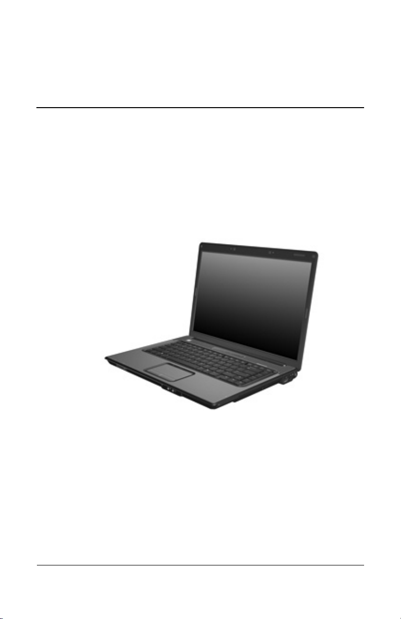
The Compaq Presario V6000 Notebook PC offers advanced
modularity, Intel Core™ Duo and Celeron™ and AMD Turion™
64 Mobile Technology and Mobile AMD Sempron™ processors,
and extensive multimedia support.
Compaq Presario V6000 Notebook PC
Maintenance and Service Guide 1–1
Page 8

Product Description
1.1 Fe a t ur es
■ The following processors are available, varying by
computer model:
■ Intel Core Duo T7200 (2.00-GHz)
■ Intel Core Duo T1350 (1.86-GHz)
■ Intel Core Duo T5600 (1.83-GHz)
■ Intel Core Duo T2250 (1.73-GHz)
■ Intel Core Duo T5500 (1.66-GHz)
■ Intel Core Duo T5200 (1.66-GHz)
■ Intel Core Duo T2050 (1.60-GHz)
■ Intel Celeron 430 (1.73-GHz)
■ Intel Celeron 420 (1.60-GHz)
■ AMD Turion ML-60 (2.0-GHz)
■ AMD Turion ML-56 (1.8-GHz)
■ AMD Turion ML-52 (1.6-GHz)
■ AMD Turion ML-50 (1.6-GHz)
■ Mobile AMD Sempron 3500+ (1.8-GHz)
■ Mobile AMD Sempron 3400+ (1.8-GHz)
■ Mobile AMD Sempron 3200+ (1.6-GHz)
■ 15.4-inch WXGA (1280 × 768) TFT display with over
16.7 million colors, varying by computer model
■ 120-, 100-, 80-, 60-, and 40-GB high-capacity hard drive,
varying by computer model
■ 256-MB DDR synchronous DRAM (SDRAM) at 667 MHz,
expandable to 2.0 GB
■ Microsoft® Windows® XP Home Edition or Windows XP
Professional, or Free DOS, varying by computer model
■ Full-size Windows keyboard with embedded numeric keypad
■ TouchPad pointing device with on/off button and dedicated
two-way scroll zone
1–2 Maintenance and Service Guide
Page 9

Product Description
■ Integrated 10/100 BASE-T Ethernet local area network
(LAN) network interface card (NIC) with RJ-45 jack
■ Integrated high-speed 56K modem with RJ-11 jack
■ Integrated wireless support for Mini Card IEEE 802.11b and
802.11b/g WLAN device
■ Support for ExpressCard
■ External 90- or 65-watt AC adapter with 3-wire power cord
■ 6-cell or 12-cell Li-Ion battery
■ Stereo speakers with volume up and down buttons
■ Integrated microphones (select models only)
■ Support for the following optical drives:
❏ DVD±RW/R and CD-RW Double-Layer Combo Drive
with LightScribe
❏ DVD±RW/R and CD-RW Double-Layer Combo Drive
❏ DVD/CD-RW Combo Drive
■ Connectors:
❏ Audio-in (microphone)
❏ Audio-out (headphone)
❏ Consumer infrared lens
❏ Docking (select models only)
❏ ExpressCard
❏ External monitor
❏ IEEE 1394 digital (select models only)
❏ Memory Reader (select models only)
❏ Power
❏ RJ-11 (modem)
❏ RJ-45 (network)
❏ S-Video-out (select models only)
❏ Universal Serial Bus (USB) v. 2.0
Maintenance and Service Guide 1–3
Page 10

Product Description
1.2 Resetting the Computer
If the computer you are servicing has an unknown password,
follow these steps to clear the password. These steps also
clear CMOS:
1. Prepare the computer for disassembly (refer to Section 5.3,
“Preparing the Computer For Disassembly,” for more
information).
2. Remove the real-time clock (RTC) battery (refer to
Section 5.7, “RTC Battery,” for more information).
3. Wait approximately 5 minutes.
4. Replace the RTC battery and reassemble the computer.
5. Connect AC power to the computer. Do not reinsert any
batteries at this time.
6. Turn on the computer.
All passwords and all CMOS settings have been cleared.
1–4 Maintenance and Service Guide
Page 11

1. 3 Powe r m a n a g e m e n t
The computer comes with power management features that
extend battery operating time and conserve power. The
computer supports the following power management features:
■ Standby
■ Hibernation
■ Setting customization by the user
■ Hotkeys for setting the level of performance
■ Battery calibration
■ Lid switch standby/resume
■ Power button
■ Advanced Configuration and Power Management (ACPM)
compliance
Product Description
Maintenance and Service Guide 1–5
Page 12
Product Description
1.4 External Components
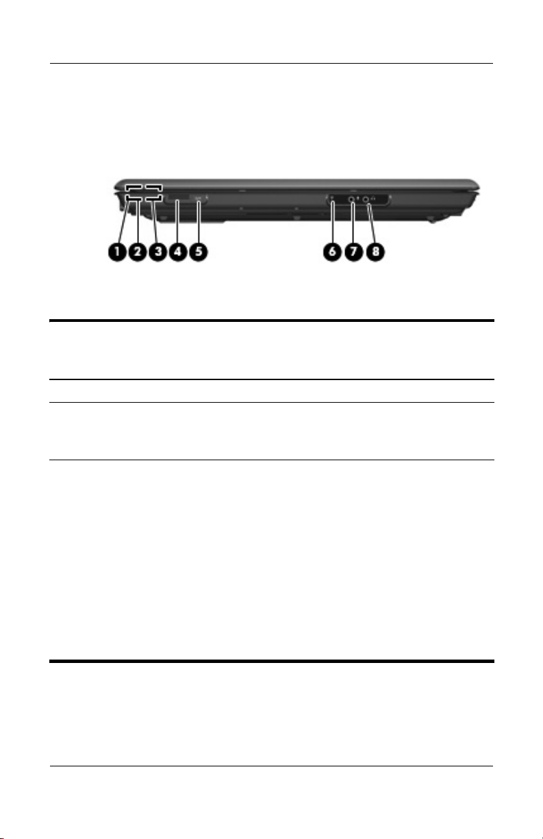
The external components on the front of the computer are shown
below and described in Table 1-1.
Front Components
Tabl e 1-1
Front Components
Item Component Function
1 Power light On: The computer is on.
Blinking: The computer is in standby.
Off: The computer is off or in hibernation.
2 Battery light On: A battery is charging.
Blinking: A battery that is the only available
power source has reached a low-battery
condition. When the battery reaches a
critical
low-battery condition, the battery
light begins blinking rapidly.
Off: If the computer is plugged into an
external power source, the light is turned off
when all batteries in the computer are fully
charged. If the computer is not plugged into
an external power source, the light stays off
until the battery reaches a low-battery
condition.
1–6 Maintenance and Service Guide
Page 13

Tabl e 1-1
Product Description
Front Components
Item Component Function
3 Drive light Blinks when the hard drive or optical drive is
being accessed.
4 Wireless switch Turns the wireless feature on or off, but
does not create a wireless connection.
✎
5 Wireless light Blue: An integrated wireless device, such as
a wireless local area network (LAN) device
and/or a Bluetooth® device, is turned on.
Amber: All wireless devices are turned off.
6 Consumer infrared
lens (select models
only)
7Audio-in
(microphone) jack
8Audio-out
(headphone) jack
Receives a signal from the HP Remote
Control.
Connects an optional computer headset
microphone, stereo array microphone, or
monaural microphone.
Produces sound when connected to
optional powered stereo speakers,
headphones, ear buds, a headset, or
television audio.
(Continued)
A wireless network must be set up to
establish a wireless connection.
Maintenance and Service Guide 1–7
Page 14
Product Description
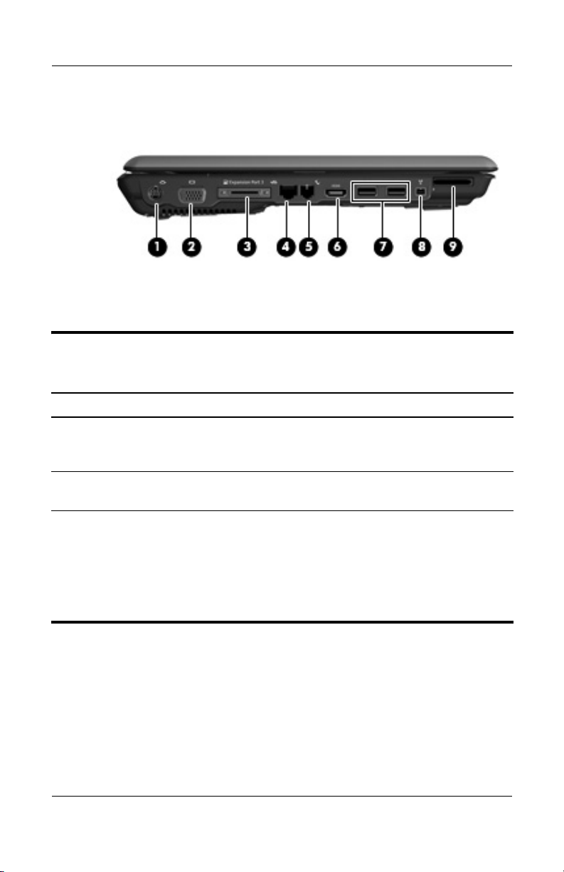
The external components on the left side of the computer are
shown below and described in Table 1-2.
Left-Side Components
Tabl e 1-2
Left-Side Components
Item Component Function
1 S-Video-out jack Connects an optional S-Video device such
as a television, VCR, camcorder, overhead
projector, or video capture card.
2 External monitor port Connects an external VGA monitor or
projector.
3 Expansion port 3 Connects the computer to an optional
expansion product.
The computer has only one
✎
expansion port. The term
describes the type of
port 3
expansion port.
1–8 Maintenance and Service Guide
expansion
Page 15

Tabl e 1-2
Product Description
Left-Side Components
Item Component Function
4 RJ-45 (network) jack Connects a network cable.
5 RJ-11 (modem) jack Connects a modem cable.
6 HDMI port (select
models only)
7 USB ports (2) Connect optional USB devices.
8 1394 port (select
models only)
9 Memory Reader
(select models only)
Connects an optional audio or video device,
such as a high definition television, set-top
box, DVD player, or any compatible digital
or audio device.
Connects an optional IEEE 1394 or 1394a
device, such as a camcorder.
Supports the following optional digital card
formats: Secure Digital (SD) Memory Card,
MultiMediaCard (MMC), Secure Digital
Input/Output (SD I/O), Memory Stick (MS),
Memory Stick Pro (MSP), xD-Picture Card
(XD), xDPicture Card (XD) Type M.
(Continued)
Maintenance and Service Guide 1–9
Page 16
Product Description
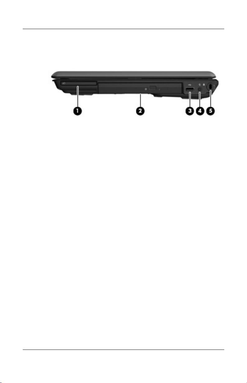
The external components on the right side of the computer
are shown below and described in Table 1-3.
Right-Side Components
1–10 Maintenance and Service Guide
Page 17

Product Description
Tabl e 1-3
Right-Side Components
Item Component Function
1 ExpressCard slot Supports optional ExpressCard/54 cards.
2 Optical drive Reads an optical disc.
3 USB port (select
models only)
4 Power connector Connects an AC adapter.
5 Security cable slot Attaches an optional security cable to the
Connects an optional USB device.
computer.
The security cable is designed to act
✎
as a deterrent, but it may not prevent
the computer from being mishandled
or stolen.
Maintenance and Service Guide 1–11
Page 18
Product Description
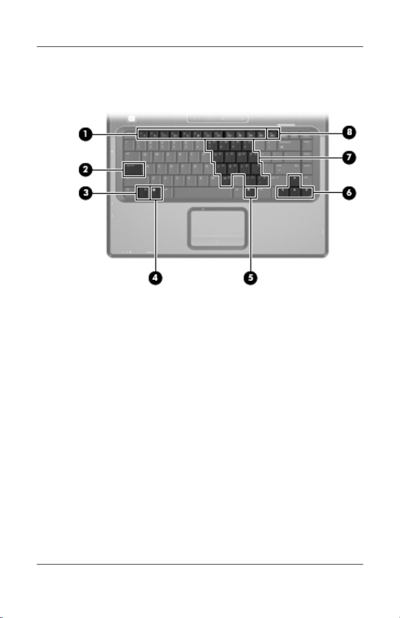
The computer keyboard components are shown below and
described in Table 1-4.
Keyboard Components
1–12 Maintenance and Service Guide
Page 19

Product Description
Table 1-4
Keyboard Components
Item Component Function
1 Function keys Execute frequently used system functions
when pressed in combination with the
fn key.
2 caps lock key Enables caps lock and turns on the caps
lock light.
3 fn
4 Windows logo key Displays the Microsoft Windows Start
5Windows
6 Arrow keys Move the cursor around the screen.
7 Embedded numeric
8 num lock key Enables numeric lock, turns on the
key Executes frequently used system
functions when pressed in combination
with a function key or the esc key.
menu.
Displays a shortcut menu for items
applications key
keypad keys
beneath the pointer.
Can be used like the keys on an external
numeric keypad.
embedded numeric keypad, and turns
on the num lock light.
Maintenance and Service Guide 1–13
Page 20
Product Description
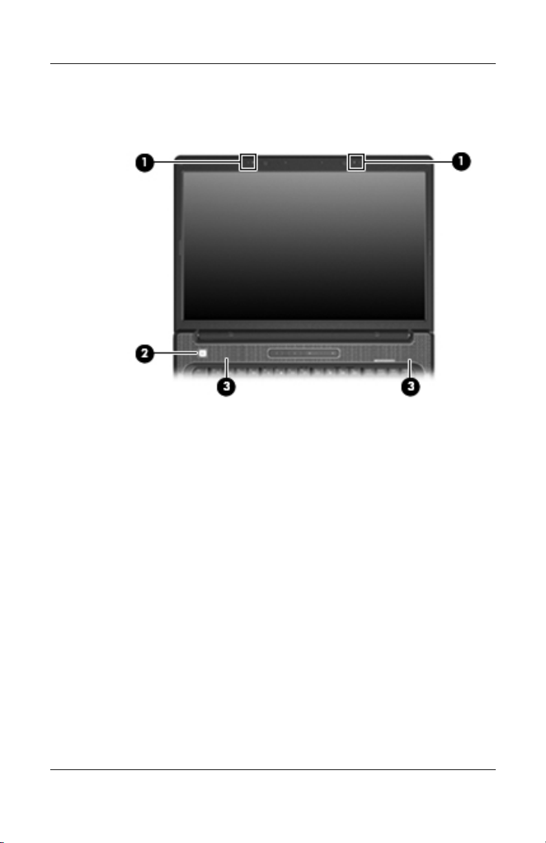
The computer top components are shown below and described in
Table 1-5.
Top Components, Part 1
1–14 Maintenance and Service Guide
Page 21

Tabl e 1-5
Top Components, Part 1
Item Component Function
Product Description
1 Internal microphones
(2, select models only)
2 Power button When the computer is
3 Speakers (2) Produce sound.
Record sound.
If there is a microphone icon next
✎
to each microphone opening, your
computer has internal microphones.
■ Off, press to turn on the computer.
■ On, press to enter hibernation.
■ In standby, briefly press to exit standby.
■ In hibernation, briefly press to
exit hibernation.
If the computer has stopped responding
and Microsoft® Windows® shutdown
procedures cannot be used, press and hold
the power button for at least 5 seconds to
turn off the computer.
Maintenance and Service Guide 1–15
Page 22
Product Description
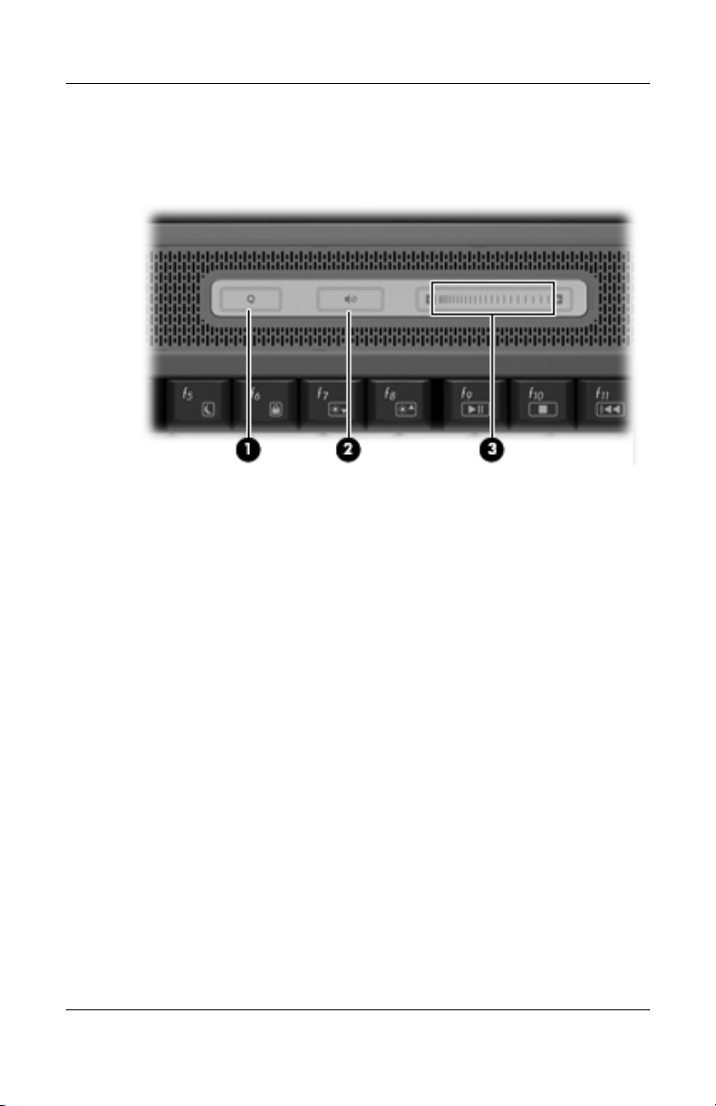
The computer top components are shown below and described in
Table 1-6.
Top Components, Part 2
1–16 Maintenance and Service Guide
Page 23

Product Description
Tabl e 1-6
Top Components, Part 2
Item Component Function
1 Media button If QuickPlay is not installed and the
computer is
■ On, opens the music program or Media
menu, which allows you to select a
multimedia program.
■ Off, does not function.
■ In standby, resumes from standby into
Windows.
If QuickPlay is installed and the computer is
■ On, opens the music program or Media
menu, which allows you to select a
multimedia program.
■ Off, opens the music program or the
Media menu, which allows you to select
a multimedia program.
■ In standby, resumes from standby into
Windows.
The media button does not affect the
✎
procedure for restoring from
hibernation.
2 Volume mute button Mutes and restores speaker sound.
3 Volume scroll zone Adjusts speaker volume. Slide your finger to
the left to decrease volume and to the right
to increase volume. You can also tap the
minus sign on the scroll zone to decrease
volume, or you can tap the plus sign on the
scroll zone to increase volume.
Maintenance and Service Guide 1–17
Page 24
Product Description
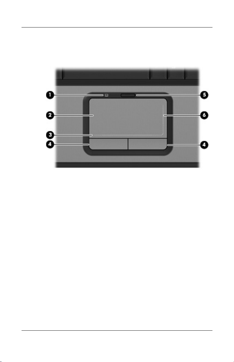
The computer TouchPad components are shown below and
described in Table 1-7.
TouchPad Components
1–18 Maintenance and Service Guide
Page 25

Product Description
Tabl e 1-7
Touchpad Components
Item Component Function
1 TouchPad light Blue: TouchPad is enabled.
Amber: TouchPad is disabled.
2 TouchPad Moves the pointer and selects or activates
items on the screen.
3 TouchPad horizontal
scroll zone
4 Left and right
TouchPad buttons
5 TouchPad on/off
button
6 TouchPad vertical
scroll zone
Allows you to scroll left or right.
Function like the left and right buttons on an
external mouse.
Enables/disables the TouchPad.
Allows you to scroll up or down.
Maintenance and Service Guide 1–19
Page 26
Product Description
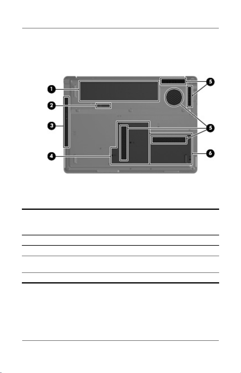
The external components on the bottom of the computer
are shown below and described in Table 1-8.
Bottom Components
Table 1 - 8
Bottom Components
Item Component Function
1 Battery bay Holds the battery.
2 Battery release latch Releases the battery from the
battery bay.
3 Optical drive Reads an optical disc.
1–20 Maintenance and Service Guide
Page 27

Table 1 - 8
Product Description
Bottom Components
Item Component Function
4 Memory module
compartment
5 Vents (5) Enable airflow to cool internal
6 Hard drive bay Holds the hard drive.
(Continued)
Contains the memory module slots, the
Mini Card WLAN slot, and the
RTC battery.
components.
To prevent overheating, do not
Ä
obstruct vents. Use the computer
only on a hard, flat surface. Do
not allow another hard surface,
such as an adjoining optional
printer, or a soft surface, such as
pillows or thick rugs or clothing, to
block airflow.
The computer fan starts up
✎
automatically to cool internal
components and prevent
overheating. It is normal for the
internal fan to cycle on and off
during routine operation.
Maintenance and Service Guide 1–21
Page 28

Product Description
1. 5 D e s i g n ove r v i ew
This section presents a design overview of key parts and features
of the computer. Refer to Chapter 3, “Illustrated Parts Catalog,”
to identify replacement parts, and Chapter 5, “Removal and
Replacement Procedures,” for disassembly steps.
The system board provides the following device connections:
■ AMD Turion and Mobile AMD Sempron processors
■ Audio
■ Display
■ ExpressCard
■ Fan
■ Hard drive
■ Intel Core Duo and Celeron processors
■ Keyboard and TouchPad
■ Memory module
■ Mini Card module
CAUTION: To properly ventilate the computer, allow at least a 7.6-cm
Ä
(3-inch) clearance on the left and right sides of the computer.
The computer uses an electric fan for ventilation. The fan is
controlled by a temperature sensor and is designed to turn on
automatically when high temperature conditions exist. These
conditions are affected by high external temperatures, system
power consumption, power management/battery conservation
configurations, battery fast charging, and software. Exhaust air is
displaced through the ventilation grill located on the left side of
the computer.
1–22 Maintenance and Service Guide
Page 29

WARNING: Only authorized technicians trained by HP should repair
Å
this equipment. All troubleshooting and repair procedures are detailed
to allow only subassembly-/module-level repair. Because of the
complexity of the individual boards and subassemblies, do not attempt
to make repairs at the component level or modifications to any printed
wiring board. Improper repairs can create a safety hazard. Any
indication of component replacement or printed wiring board
modification may void any warranty or exchange allowances.
2.1 Setup Utility
The Setup Utility is a ROM-based information and customization
utility that can be used even when your Windows operating
system is not working or will not load.
The utility reports information about the computer and provides
settings for startup, security, and other preferences.
1. Turn on or restart the computer in Windows.
2
Troubleshooting
2. Before Windows opens and while the “Press <F10> to enter
setup” prompt is displayed in the lower-left corner of the
screen, press
Maintenance and Service Guide 2–1
f10.
Page 30

Troubleshooting
2.2 Using the Setup Utility
Changing the Language of the Setup Utility
The following procedure explains how to change the language of
the Setup Utility. If the computer is not in the Setup Utility, begin
at step 1. If the computer is in the Setup Utility, begin at step 2.
1. To open the Setup Utility, turn on or restart the computer in
Windows, and then press
to enter setup,” is displayed in the lower-left corner of the
screen.
2. Use the arrow keys to select System Configuration >
Language, and then press
f10 while the prompt, “Press <F10>
enter.
3. Press
f5 or f6 (or use the arrow keys) to select a language, and
then press
enter to select a language.
4. When a confirmation prompt with your preference selected is
displayed, press
5. To set your preferences and exit the Setup Utility, press
enter to save your preference.
f10
and then follow the instructions on the screen.
Your preferences go into effect when the computer restarts in
Windows.
2–2 Maintenance and Service Guide
Page 31

Troubleshooting
Navigating and Selecting in the Setup Utility
Because the Setup Utility is not Windows-based, it does not
support the TouchPad. Navigation and selection are by keystroke.
■ To choose a menu or a menu item, use the arrow keys.
■ To choose an item in a drop-down list or to toggle a field, for
example an Enable/Disable field, use either the arrow keys
f5 or f6.
or
■ To select an item, press enter.
■ To close a text box or return to the menu display, press f1.
■ To display additional navigation and selection information
while the Setup Utility is open, press
f1.
Displaying System Information
The following procedure explains how to display system
information in the Setup Utility. If the Setup Utility is not open,
begin at step 1. If the Setup Utility is open, begin at step 2.
1. To open the Setup Utility, turn on or restart the computer in
Windows, and then press
to enter setup,” is displayed in the lower-left corner of the
screen.
f10 while the prompt, “Press <F10>
2. Access the system information by using the Main menu.
3. To close the Setup Utility without changing any settings, use
the arrow keys to select Exit > Exit Discarding Changes,
and then press
Maintenance and Service Guide 2–3
enter. (The computer restarts in Windows.)
Page 32

Troubleshooting
Restoring Default Settings in the
Setup Utility
The following procedure explains how to restore the Setup Utility
default settings. If the computer is not in the Setup Utility, begin
at step 1. If the computer is in the Setup Utility, begin at step 2.
1. To open the Setup Utility, turn on or restart the computer in
Windows, and then press
to enter setup,” is displayed in the lower-left corner of the
screen.
f10 while the prompt, “Press <F10>
2. Select Exit > Load Setup Defaults, and then press
3. When the Setup Confirmation is displayed, press
your preferences.
4. To set your preferences and exit the Setup Utility, press
and then follow the instructions on the screen.
The Setup Utility default settings are set when you exit the Setup
Utility and go into effect when the computer restarts.
Your password, security, and language settings are not changed
✎
when you restore the factory default settings.
enter to save
Using Advanced Setup Utility Features
This guide describes the Setup Utility features recommended for
all users. For more information about the Setup Utility features
recommended for advanced users only, refer to the Help and
Support Center, which is accessible only when the computer is
in Windows.
The Setup Utility features available for advanced users include a
hard drive self-test, a Network Service Boot, and settings for boot
order preferences.
f10.
f10,
2–4 Maintenance and Service Guide
Page 33

The “<F12> to boot from LAN” message that is displayed in the
lower-left corner of the screen each time the computer is started
or restarted in Windows or restored from hibernation is the
prompt for a Network Service Boot.
The “Press <ESC> to change boot order” message that is
displayed in the lower-left corner of the screen each time the
computer is started or restarted in Windows or restored from
hibernation is the prompt to change the boot order.
Closing the Setup Utility
You can close the Setup Utility with or without saving changes.
■ To close the Setup Utility and save your changes from the
current session, use either of the following procedures:
❏ Press f10, and then follow the instructions on the screen.
– or –
❏ If the Setup Utility menus are not visible, press esc to
return to the menu display. Then use the arrow keys to
select Exit > Exit Saving Changes, and then press
When you use the
to return to the Setup Utility. When you use the Exit
Saving Changes procedure, the Setup Utility closes when
you press
■ To close the Setup Utility without saving your changes from
enter.
the current session:
f10 procedure, you are offered an option
Troubleshooting
enter.
If the Setup Utility menus are not visible, press
esc to return
to the menu display. Then use the arrow keys to select Exit >
Exit Discarding Changes, and then press
enter.
After the Setup Utility closes, the computer restarts in Windows.
Maintenance and Service Guide 2–5
Page 34

Troubleshooting
2.3 Setup Utility Menus
The menu tables in this section provide an overview of Setup
Utility options.
Some of the Setup Utility menu listed in this chapter may not
✎
be supported by your computer.
Selecting from the Main Menu
Table 2 - 1
Main Menu
Select To Do This
System Information ■ View and change the system time and date.
■ View identification information about the
computer.
■ View specification information about the
processor, memory size, system BIOS,
and keyboard controller version (select
models only).
Selecting from the Security Menu
Table 2 - 2
Security Menu
Select To Do This
Administrator password Enter, change, or delete an administrator
password.
Power-on password Enter, change, or delete a power-on password.
2–6 Maintenance and Service Guide
Page 35

Selecting from the System
Configuration Menu
Table 2 - 3
System Configuration Menu
Select To Do This
Language Support Change the Setup Utility language.
Troubleshooting
Embedded WLAN Device
Radio
Embedded Bluetooth
Device (select models only)
Enhanced SATA support
Enable/disable an embedded wireless LAN
device.
Enable/disable an embedded Bluetooth device
(select models only).
Enable/disable enhanced SATA mode.
(select models only)
Boot Options Set the following boot options:
■ f10 and f12 Delay (sec.)—Set the delay for the
f10 and f12 functions of the Setup Utility in
intervals of 5 seconds each (0. 5, 10, 15, 20).
■ CD-ROM boot—Enable/disable boot from
CD-ROM.
■ Floppy boot—Enable/disable boot from Floppy.
■ Internal Network Adapter boot—Enable/disable
boot from Internal Network Adapter.
■ Boot Order—Set the boot order for:
❐ USB Floppy
❐ ATAPI CD/DVD ROM Drive
❐ Hard drive
❐ USB Diskette on Key
❐ USB Hard drive
❐ Network adapter
Maintenance and Service Guide 2–7
Page 36

Troubleshooting
Selecting from the Diagnostics Menu
Table 2 - 4
Diagnostics Menu
Select To Do This
Hard Disk Self Test Run a comprehensive self-test on the hard drive.
On models with two hard drives, this menu
✎
option is called the Primary Hard Disk Self
Test.
Secondary Hard Disk Self
Test (select models only)
Run a comprehensive self-test on a secondary
hard drive.
2–8 Maintenance and Service Guide
Page 37

Troubleshooting
2.4 Troubleshooting Flowcharts
Tabl e 2-5
Troubleshooting Flowcharts Overview
Flowchart Description
2.1 “Flowchart 2.1—Initial Troubleshooting”
2.2 “Flowchart 2.2—No Power, Part 1”
2.3 “Flowchart 2.3—No Power, Part 2”
2.4 “Flowchart 2.4—No Power, Part 3”
2.5 “Flowchart 2.5—No Power, Part 4”
2.6 “Flowchart 2.6—No Video, Part 1”
2.7 “Flowchart 2.7—No Video, Part 2”
2.8 “Flowchart 2.8—Nonfunctioning Docking Device (if applicable)”
2.9 “Flowchart 2.9—No Operating System (OS) Loading”
2.10 “Flowchart 2.10—No OS Loading, Hard Drive, Part 1”
2.11 “Flowchart 2.11—No OS Loading, Hard Drive, Part 2”
2.12 “Flowchart 2.12—No OS Loading, Hard Drive, Part 3”
2.13 “Flowchart 2.13—No OS Loading, Diskette Drive”
Maintenance and Service Guide 2–9
Page 38

Troubleshooting
Tabl e 2-5
Troubleshooting Flowcharts Overview
Flowchart Description
2.14 “Flowchart 2.14—No OS Loading, Optical Drive”
2.15 “Flowchart 2.15—No Audio, Part 1”
2.16 “Flowchart 2.16—No Audio, Part 2”
2.17 “Flowchart 2.17—Nonfunctioning Device”
2.18 “Flowchart 2.18—Nonfunctioning Keyboard”
2.19 “Flowchart 2.19—Nonfunctioning Pointing Device”
2.20 “Flowchart 2.20—No Network/Modem Connection”
(Continued)
2–10 Maintenance and Service Guide
Page 39

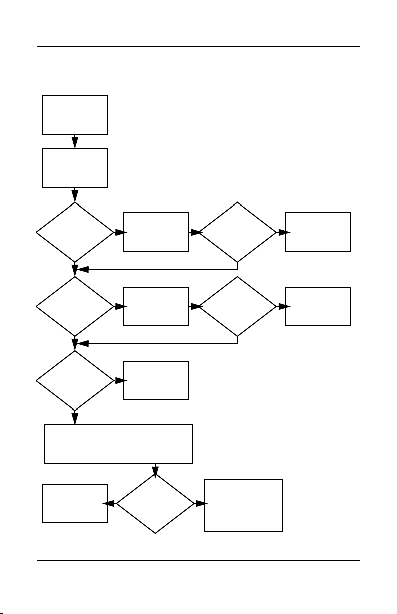
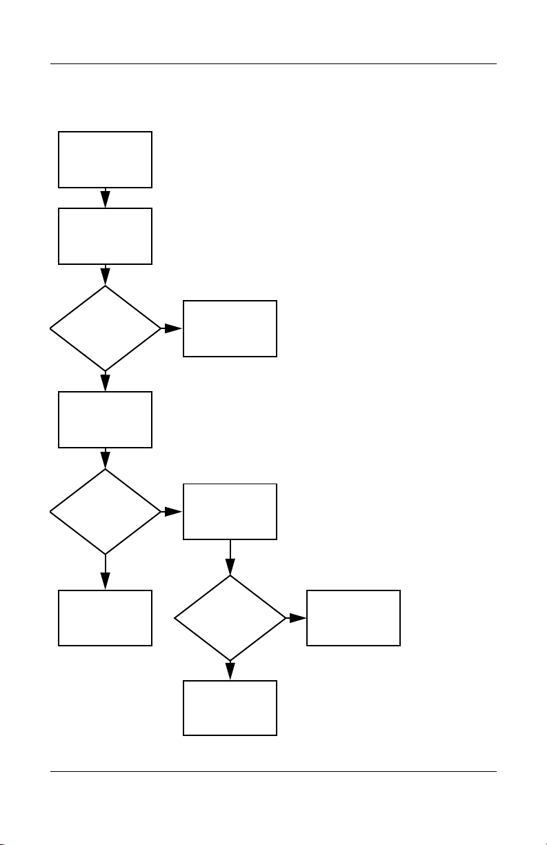
Flowchart 2.1—Initial Troubleshooting
Begin
troubleshooting.
N
Go to
Is there
power?
Y
N
Beeps,
LEDs, or error
messages?
Y
N
Is there video?
(no boot)
Y
N
Is the OS
loading?
Y
N
Is there
sound?
Y
“Flowchart
2.2—No Power,
Par t 1.”
Check
LED board,
speaker
connections.
Go to
“Flowchart
2.6—No Video,
Part 1.”
Go to
“Flowchart
2.9—No Operating
System (OS)
Loading.”
Go to
“Flowchart
2.15—No Audio,
Par t 1.”
N
All drives
working?
Y
N
Keyboard/
pointing
device
working?
Y
N
Connecting
to network
or modem?
Y
End
Troubleshooting
Go to
“Flowchart
2.17—Nonfunctioning Device.”
Go to
“Flowchart
2.18—Nonfunc-
tioning Keyboard”
or “Flowchart
2.19—Nonfunctioning Pointing
Device.”
Go to
“Flowchart
2.20—No
Network/Modem
Connection.”
Maintenance and Service Guide 2–11
Page 40
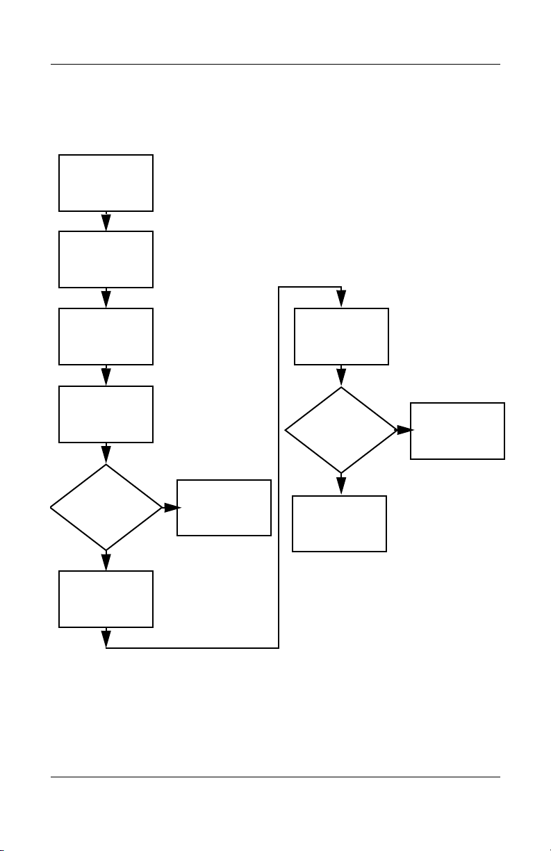
Troubleshooting
N
Flowchart 2.2—No Power, Part 1
No power
(power LED
is off).
Remove from
docking device
(if applicable).
Y
Y
Power up
on battery
power?
Power up
on AC
power?
N
Reset
power.*
Power up
on battery
power?
Y
N
Reset
power.*
Power up
on AC power?
Y
N
Go to
“Flowchart
2.3—No Power,
Par t 2.”
N
Go to
“Flowchart
2.4—No Power,
Part 3.”
Y
Power up in
docking
device?
1. Reseat the power cables in the docking
device and at the AC outlet.
2. Ensure the AC power source is active.
3. Ensure that the power strip is working.
Done
YN
Done
Power up
in docking
device?
*NOTES
1. On select models, there is a separate
reset button.
2. On select models, the computer can be
reset using the standby switch and either
the lid switch or the main power switch.
Go to
“Flowchart
2.8—Nonfunctioning
Docking Device (if
applicable).”
2–12 Maintenance and Service Guide
Page 41

Flowchart 2.3—No Power, Part 2
N
Continued from
“Flowchart
2.2—No Power,
Par t 1.”
Visually check for
debris in battery
socket and clean
if necessary.
Y
Troubleshooting
Power on?
Check battery by
recharging it,
moving it to
another computer,
or replacing it.
Done
N
Power on?
Replace
power supply
(if applicable).
Y
N
Go to
Done
Power on?
“Flowchart
2.4—No Power,
Part 3.”
Y
Done
Maintenance and Service Guide 2–13
Page 42

Troubleshooting
Flowchart 2.4—No Power, Part 3
Continued from
“Flowchart
2.3—No Power,
Part 2.”
Plug directly
into AC outlet.
Y
Power LED
on?
N
Reseat AC adapter
in computer and
at power source.
Power on?
N
Power outlet
active?
Y
Replace
power cord.
Power on?
Done
Y
Done
External
N
Try different
outlet.
Internal or
external AC
adapter?
Internal
Go to
“Flowchart
2.5—No Power,
Part 4.”
Replace external
AC adapter.
N
Power on?
Y
Y
Done
Done
N
2–14 Maintenance and Service Guide
Page 43

Flowchart 2.5—No Power, Part 4
Continued from
“Flowchart
2.4—No Power,
Par t 3.”
Open
computer.
Troubleshooting
N
Y
Loose or
damaged
parts?
Close
computer and
retest.
Power on?
Done
Y
Reseat loose
components and
boards and
replace damaged
items.
N
Replace the following items (if applicable). Check
computer operation after each replacement:
1. Internal DC-DC converter*
2. Internal AC adapter
3. Processor board*
4. System board*
*NOTE: Replace these items as a set to prevent
shorting out among components.
Maintenance and Service Guide 2–15
Page 44

Troubleshooting
Flowchart 2.6—No Video, Part 1
No video.
Docking Device
Stand-alone
or docking
device?
Go to
“Flowchart
2.7—No Video,
Part 2.”
*NOTE: To change from internal to
external display, use the hotkey
combination.
Stand-alone
Internal or
external
display*?
External
Adjust
brightness.
Internal
Y
Video OK? Done
N
Check for bent
pins on cable.
N
Video OK?
Adjust
brightness.
Video OK? Done
N
A
Press lid
switch to ensure
operation.
Video OK? Done
N
Replace the following one at a time. Test after each replacement.
1. Cable between computer and computer display (if applicable)
2. Display
3. System board
Try
another
display.
Internal and
external
video OK?
Y
Y
N
Replace
system
board.
YY
Done
Done
2–16 Maintenance and Service Guide
Page 45

Flowchart 2.7—No Video, Part 2
Continued from
“Flowchart
2.6—No Video,
Part 1.”
Remove
computer from
docking device,
if connected.
Troubleshooting
Adjust
display
brightness.
N
Video OK?
Y
Check that computer is properly
seated in docking device,
for bent pins on cable,
and for monitor connection.
Y
Video OK?
N
Adjust external
monitor display.
Go to “A” in
“Flowchart
2.6—No Video,
Part 1.”
Done
Check brightness
of external
monitor.
Video OK?
N
Try another
external
monitor.
Internal
and external
video OK?
N
Go to
“Flowchart
2.8—Nonfunctioning
Docking Device (if
applicable).”
Y
Done
Y
Done
Maintenance and Service Guide 2–17
Page 46
Troubleshooting
Flowchart 2.8—Nonfunctioning Docking Device
(if applicable)
Nonfunctioning
docking device.
Reseat power
cord in docking
device and
power outlet.
Check voltage
setting on docking
device.
Reset monitor
cable connector at
docking device.
Docking
device
operating?
N
Remove computer,
replace docking
device.
Reinstall
computer into
docking device.
Y
Docking
device
operating?
Y
Done
N
Test replacement
docking device with
new computer.
Done
2–18 Maintenance and Service Guide
Page 47
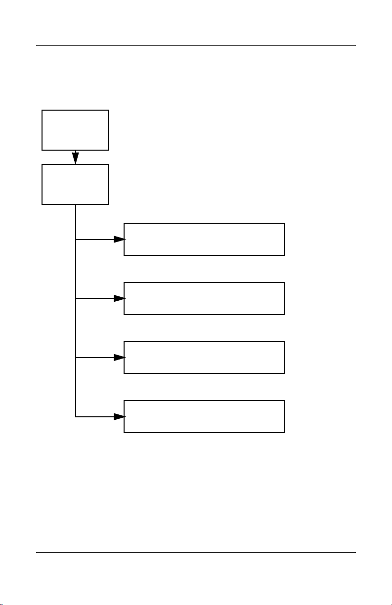
Troubleshooting
Flowchart 2.9—No Operating System (OS)
Loading
No OS
loading.*
Reseat power
cord in docking
device and
power outlet.
No OS loading from hard drive,
“Flowchart 2.10—No OS Loading,
go to
go to
Hard Drive, Part 1.”
No OS loading from diskette drive,
“Flowchart 2.13—No OS Loading,
Diskette Drive.”
No OS loading from optical drive,
“Flowchart 2.14—No OS Loading,
go to
“Flowchart 2.20—No Network/Modem
go to
*NOTE: Before beginning troubleshooting, always
check cable connections, cable ends, and drives
for bent or damaged pins.
Optical Drive.”
No OS loading from network,
Connection.”
Maintenance and Service Guide 2–19
Page 48

Troubleshooting
Flowchart 2.10—No OS Loading, Hard Drive,
Part 1
OS not
loading from
hard drive.
Nonsystem
disk message?
N
Reseat
external
hard drive.
OS loading?
N
Boot
from
CD?
Y
Check the Setup
utility for correct
booting order.
Boot
from
hard drive?
Y
Done
Y
Go to
“Flowchart
2.11—No OS
Loading,
Hard Drive, Part 2.”
Y
Done
N
N
Boot
from
diskette?
Y
N
Change boot
priority through
the Setup Utility
and reboot.
Go to
“Flowchart
2.13—No OS
Loading,
Diskette Drive.”
N
Boot
from
hard drive?
2.17—Nonfunctioning
Go to
“Flowchart
Device.”
Y
2–20 Maintenance and Service Guide
Page 49

Troubleshooting
Flowchart 2.11—No OS Loading, Hard Drive,
Part 2
Continued from
“Flowchart
2.10—No OS
Loading,
Hard Drive, Part 1.”
Disc or
diskette in
drive?
Y
Remove disc or
diskette and
reboot.
N
1. Replace
hard drive.
2. Replace system
board.
N
Reseat
hard drive.
Hard drive
accessible?
Run FDISK.
Y
Done
N
from diskette
Y
Boot
from
hard drive?
Boot
drive?
Y
N
Diskette Drive.”
Done
Go to
“Flowchart
2.13—No OS
Loading,
Hard drive
partitioned?
Y
Hard drive
formatted?
Y
N
Create partition,
and then format
hard drive to
bootable
C:\ prompt.
N
Format hard drive
and bring to
abootable
C:\ prompt.
N
Y
Computer
booted?
Load OS using
Operating System disc
(if applicable).
Y
Hard drive
accessible?
Done
N
Go to
“Flowchart
2.12—No OS
Loading,
Hard Drive, Part 3.”
Maintenance and Service Guide 2–21
Go to
“Flowchart
2.12—No OS
Loading,
Hard Drive, Part 3.”
Page 50

Troubleshooting
Flowchart 2.12—No OS Loading, Hard Drive,
Part 3
Continued from
“Flowchart
2.11—No OS
Loading,
Hard Drive, Part 2.”
N
System
files on hard
drive?
Y
Install OS
and reboot.
Virus
on
hard drive?
N
Run SCANDISK and
check for
bad sectors.
Can bad
sectors
be fixed?
Y
Fix bad
sectors.
Y
OS
Clean virus.
loading from
hard drive?
Y
Done
N
Y
Diagnostics on
disc or diskette?
Replace
hard drive.
N
N
Replace
hard drive.
Run diagnostics
and follow
recommendations.
N
Boot from
hard drive?
Replace
hard drive.
Y
Done
2–22 Maintenance and Service Guide
Page 51

Troubleshooting
N
N
Flowchart 2.13—No OS Loading, Diskette Drive
Y
OS not loading
from
diskette drive.
Reseat
diskette drive.
OS
loading?
Done
N
Nonsystem
disk message?
Y
Bootable
diskette
in drive?
N
Install bootable
diskette and
reboot computer.
Y
N
Boot
from another
device?
Y
Go to
“Flowchart
2.17—Nonfunctioning Device.”
N
Diskette
drive enabled
in the Setup
utility?
Enable drive
and cold boot
computer.
Y
Y
Reset the computer.
Is diskette
drive boot
order
correct?
Refer to
Section 1.2,
“Resetting the
Computer,”
instructions.
for
Check diskette
for system files.
Try d iff ere nt
diskette.
Nonsystem
disk error?
N
loading?
N
OS
Y
Replace the following
components
individually, retesting
after each
replacement:
■ Diskette drive
■ System board
Y
Done
Change boot
priority using
the Setup Utility.
Go to
“Flowchart
2.17—Nonfunctioning
Device.”
Maintenance and Service Guide 2–23
Page 52

Troubleshooting
Flowchart 2.14—No OS Loading, Optical Drive
loading from
CD-ROM or
DVD-ROM drive.
Boots from
CD or DVD?
N
Reseat
No OS
drive.
N
bootable disc.
Disc
in drive?
Install
Y
Bootable
disc in
drive?
Y
Try another
bootable disc.
N
Install bootable
disc and
reboot
computer.
Y
Done
Y
Boots from
CD or DVD?
Done
N
N
Go to
“Flowchart
Device.”
Y
Booting
from another
device?
2.17—Nonfunctioning
Reset the computer.
Booting
correct?
N
Correct boot
order using
the Setup Utility.
order
Y
Refer to
Section 1.2,
“Resetting the
Computer,”
instructions.
for
2.17—Nonfunctioning
Go to
“Flowchart
Device.”
2–24 Maintenance and Service Guide
Page 53

Flowchart 2.15—No Audio, Part 1
N
Turn up audio
No audio.
internally or
externally.
Audio? Done
N
Troubleshooting
Y
Computer in
docking device
(if applicable)?
Y
Undock
Internal
audio?
N
Go to
“Flowchart
2.16—No Audio,
Par t 2.”
Y
Go to
“Flowchart
2.16—No Audio,
Par t 2.”
Replace the
docking device.
Y
Go to
“Flowchart
2.17—Nonfunctioning
Device.”
Audio? Done
N
Maintenance and Service Guide 2–25
Page 54

Troubleshooting
Flowchart 2.16—No Audio, Part 2
Continued from
“Flowchart
2.15—No Audio,
Part 1.”
N
Audio
driver in OS
configured?
Y
N
Correct
drivers for
application?
Y
Connect to
external
speaker.
Reload
audio drivers.
Load drivers and
set configuration
in OS.
Replace audio
board and
Audio?
YN
speaker
connections
in computer
(if applicable).
Audio? Done
Replace the following components
individually, retesting after each
replacement:
■ Internal speakers
■ Audio board (if applicable)
YN
2–26 Maintenance and Service Guide
Page 55

Flowchart 2.17—Nonfunctioning Device
Nonfunctioning
device.
Reseat
device.
Unplug the nonfunctioning device from the computer
and inspect cables and plugs for bent or broken pins
Clear
CMOS.
Reattach device.
Close computer,
plug in power,
and reboot.
or other damage.
Any physical
device detected?
N
Replace hard drive.
Y
Operating System
Troubleshooting
Fix or
replace
broken item.
Go to
“Flowchart
2.9—No
(OS) Loading.”
N
Device
boots
properly?
Y
Done
Replace NIC.
If integrated NIC,
replace system
board.
Y
Replace diskette
drive.
Maintenance and Service Guide 2–27
Device
boots
properly?
Done
N
Page 56
Troubleshooting
Flowchart 2.18—Nonfunctioning Keyboard
Keyboard
not operating
properly.
Connect computer
to good external
keyboard.
N
Y
Reseat internal
connector
(if applicable).
Y
External
device
works?
keyboard
Replace
system
board.
N
Keyboard
operating
properly?
Replace internal
keyboard or
cable.
Y
Keyboard
Done Done
operating
properly?
N
Replace
system
board.
2–28 Maintenance and Service Guide
Page 57

Troubleshooting
Flowchart 2.19—Nonfunctioning Pointing Device
Pointing device
not operating
properly.
Connect computer
to good external
pointing device.
N
External
device
works?
Y
Reseat internal
pointing device
connector
(if applicable).
Replace
system
board.
N
Pointing device
operating
properly?
Replace internal
pointing device
or cable.
Y
Y
Done Done
Pointing device
operating
properly?
N
Replace
system
board.
Maintenance and Service Guide 2–29
Page 58

Troubleshooting
Flowchart 2.20—No Network/Modem
Connection
No network
or modem
connection.
N
Network
or modem jack
active?
Y
Digital
line?
N
Replace jack
or have jack
activated.
Y
Connect
to nondigital
line.
Y
Done
Y
Disconnect all
the computer
NIC/modem
configured
in OS?
power from
and open.
N
Reload
drivers and
reconfigure.
Network
or modem
connection
working?
N
Replace
NIC/modem
(if applicable).
Y
Reseat NIC/modem
(if applicable).
Network
or modem
connection
working?
Done
N
Replace
system
board.
2–30 Maintenance and Service Guide
Page 59

Illustrated Parts Catalog
This chapter provides an illustrated parts breakdown and a
reference for spare part numbers and option part numbers.
3.1 Serial Number Location
When ordering parts or requesting information, provide the
computer serial number and model number located on the bottom
of the computer.
3
Maintenance and Service Guide 3–1
Page 60
Illustrated Parts Catalog
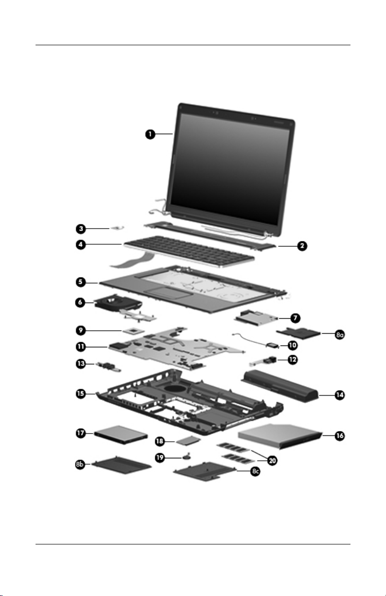
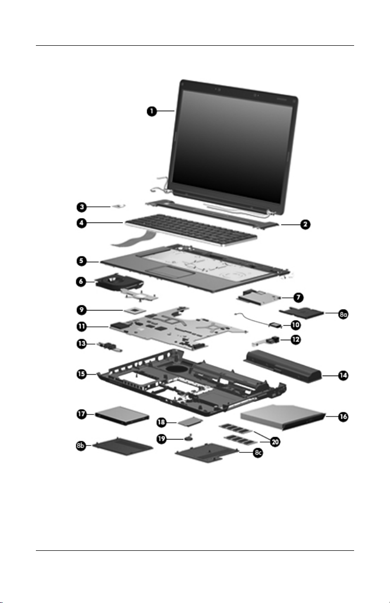
3.2 Computer Major Components
Computer Major Components
3–2 Maintenance and Service Guide
Page 61

Illustrated Parts Catalog
Table 3 - 1
Spare Parts: Computer Major Components
Spare Part
Item Description
1 Display assemblies (include wireless antenna transceivers
and cables)
For use with full-featured computer models (includes microphones)
Number
15.4-inch, WXGA, TFT with BrightView
15.4-inch, WXGA, TFT Antiglare
For use with defeatured computer models (does not
include microphones)
15.4-inch, WXGA, TFT with BrightView
15.4-inch, WXGA, TFT Antiglare
Refer to Section 3.3, “Display Assembly Components,” for
✎
display assembly internal component spare part number
information.
2 Switch covers (include LED board and LED board cable)
For use with full-featured computer models
For use with defeatured computer models
3 Power button board (includes power button
board cable)
4 Keyboards
For use with all computer models in the following countries:
France
French Canada
Italy
The
Netherlands
431415-051
431415-121
431415-061
431415-331
Spain
The United
Kingdom
The United
States
432304-001
432305-001
432302-001
432303-001
431425-001
431424-001
431438-001
431415-071
431415-031
431415-001
Maintenance and Service Guide 3–3
Page 62
Illustrated Parts Catalog
Computer Major Components
3–4 Maintenance and Service Guide
Page 63

Table 3 - 1
Illustrated Parts Catalog
Spare Parts: Computer Major Components
Item Description
4 Keyboards
For use only with computer models using Intel processors in the
following countries:
Latin America
Saudi Arabia
For use only with computer models using AMD processors in the
following countries:
Denmark,
Finland,
Norway, and
Sweden
5 Top covers (include speakers, TouchPad and TouchPad cable)
For use with full-featured computer models
For use with defeatured computer models
6 Fan/heat sink assemblies (include thermal pads)
For use only with computer models using
Intel processors
(Continued)
431415-161
431415-171
431415-DH1 Korea 431415-AD1
Ta i wa n
Thailand
(Continued)
Spare Part
Number
431415-AB1
431415-281
431417-001
431419-001
434746-001
For use only with computer models using
AMD processors
7 ExpressCard assembly 431440-001
Plastics Kit 431429-001
Includes:
8a
8b
8c
Maintenance and Service Guide 3–5
ExpressCard slot bezel
Hard drive cover (includes 2 captive screws, secured by C-clips)
Memory module compartment cover (includes 3 captive screws,
secured by C-clips)
431450-001
Page 64

Illustrated Parts Catalog
Computer Major Components
3–6 Maintenance and Service Guide
Page 65

Table 3 - 1
Illustrated Parts Catalog
Spare Parts: Computer Major Components
Item Description
9 Processors (include thermal pad)
Intel Core Duo T7200 (2.00-GHz)
Intel Core Duo T1350 (1.86-GHz)
Intel Core Duo T5600 (1.83-GHz)
Intel Core Duo T2250 (1.73-GHz)
Intel Core Duo T5500 (1.66-GHz)
Intel Core Duo T5200 (1.66-GHz)
Intel Core Duo T2050 (1.60-GHz)
Intel Celeron 430 (1.73-GHz)
Intel Celeron 420 (1.60-GHz)
AMD Turion ML-60 (2.0-GHz)
AMD Turion ML-56 (1.8-GHz)
AMD Turion ML-52 (1.6-GHz)
AMD Turion ML-50 (1.6-GHz)
Mobile AMD Sempron 3500+ (1.8-GHz)
Mobile AMD Sempron 3400+ (1.8-GHz)
Mobile AMD Sempron 3200+ (1.6-GHz)
10 Bluetooth module (includes Bluetooth
module cable)
11 System boards
(Continued)
Spare Part
Number
434730-001
430896-001
434731-001
430897-001
436157-001
436900-001
430898-001
436159-001
434735-001
436257-001
431373-001
431372-001
431371-001
434414-001
431375-001
431374-001
412766-001
For use only with full-featured computer models using
Intel processors
For use only with defeatured computer models using
Intel processors
For use only with full-featured computer models using
AMD processors
For use only with defeatured computer models using
AMD processors
Maintenance and Service Guide 3–7
434725-001
434726-001
431364-001
431365-001
Page 66

Illustrated Parts Catalog
Computer Major Components
3–8 Maintenance and Service Guide
Page 67

Table 3 - 1
Illustrated Parts Catalog
Spare Parts: Computer Major Components
Item Description
12 USB/power connector boards (include USB/power connector
board cable)
For use with 90W AC adapters
For use with 65W AC adapters
13 Audio boards
For use with full-featured computer models (includes
infrared lens)
For use with defeatured computer models (does not
include infrared lens)
14 Batteries
12-cell, 8.8-AHr
6-cell, 4.0-AHr
15 Base enclosures (include wireless switch)
For use with full-featured computer models
For use with defeatured computer models
Rubber Feet Kit (includes computer feet, not
illustrated)
16 Optical drives (include bezel)
(Continued)
Spare Part
Number
431446-001
431445-001
431443-001
431444-001
432307-001
432306-001
431427-001
432922-001
431431-001
DVD±RW/R and CD-RW Double-Layer Combo Drive
with LightScribe
DVD±RW/R and CD-RW Double-Layer Combo Drive
DVD/CD-RW Combo Drive
Maintenance and Service Guide 3–9
431413-001
431412-001
431411-001
Page 68

Illustrated Parts Catalog
Computer Major Components
3–10 Maintenance and Service Guide
Page 69

Table 3 - 1
Illustrated Parts Catalog
Spare Parts: Computer Major Components
Item Description
17 Hard drives (all 5400-rpm, include bracket and connector)
For use with all computer models:
120-GB
100-GB
80-GB
60-GB
40-GB hard drive for use only with computer models
using Intel processors
40-GB hard drive for use only with computer models
using AMD processors
Hard Drive Bracket Kit (includes hard drive bracket
and screws used to secure the bracket to the
hard drive)
18 Mini Card modules
802.11a/b/g WLAN Mini Card module for use only
with computer models using Intel processors in the
countries listed below. These countries are
categorized as most of the world 1 (MOW1).
(Continued)
Spare Part
Number
431407-001
431406-001
431405-001
431404-001
434743-001
434415-001
436156-001
407674-001
Antigua &
Barbuda
Argentina
Australia
Bahamas
Barbados
Brunei
Maintenance and Service Guide 3–11
Canada
Chile
Dominican
Republic
Guam
Guatemala
Hong Kong
Panama
India
Indonesia
Malaysia
Mexico
New Zealand
Paraguay
Saudi Arabia
Ta i wa n
The United
States
Vietnam
Page 70

Illustrated Parts Catalog
Computer Major Components
3–12 Maintenance and Service Guide
Page 71

Table 3 - 1
Illustrated Parts Catalog
Spare Parts: Computer Major Components
Item Description
18 Mini Card modules
802.11a/b/g WLAN Mini Card module for use only
with computer models using Intel processors in the
countries listed below. These countries are
categorized as most of the world 2 (MOW2).
Aruba
Austria
Azerbaijan
Bahrain
Belgium
Bermuda
Bulgaria
Cayman Islands
Columbia
Croatia
Cyprus
The Czech
Republic
Denmark
(Continued)
Egypt
El Salvador
Estonia
Finland
France
Georgia
Germany
Greece
Hungary
Iceland
Ireland
Italy
Latvia
Lebanon
The Philippines
Poland
Portugal
Romania
Russia
Serbia and
Montenegro
Singapore
Slovakia
Liechtenstein
Lithuania
Luxembourg
Malta
Monaco
(Continued)
Spare Part
Number
407674-002
The
Netherlands
Norway
Oman
Slovenia
South Africa
Spain
Sri Lanka
Sweden
Switzerland
Tu r ke y
The United
Kingdom
Uzbekistan
802.11a/b/g WLAN Mini Card module for use only
with computer models using Intel processors in the
countries listed below. These countries are
categorized as the rest of the world (ROW).
China
Ecuador
Haiti
Maintenance and Service Guide 3–13
Honduras
Pakistan
Peru
Qatar
South Korea
407674-003
Uruguay
Venezuela
Page 72

Illustrated Parts Catalog
Computer Major Components
3–14 Maintenance and Service Guide
Page 73

Table 3 - 1
Illustrated Parts Catalog
Spare Parts: Computer Major Components
Item Description
18 Mini Card modules
802.11a/b/g WLAN Mini Card module for use only
with computer models using Intel processors in Japan
802.11a/b/g WLAN Mini Card module for use only
with computer models using AMD processors in the
MOW countries listed below:
Antigua &
Barbuda
Argentina
Aruba
Australia
Austria
Azerbaijan
Bahamas
Bahrain
Barbados
Belgium
Bermuda
Brunei
Bulgaria
Canada
The Cayman
Islands
The Czech
Republic
Chile
Columbia
(Continued)
Croatia
Cyprus
Denmark
The
Dominican
Republic
Egypt
El Salvador
Estonia
Finland
France
Georgia
Germany
Greece
Guam
Guatemala
Hong Kong
Hungary
Iceland
India
Indonesia
Ireland
Italy
Latvia
Lebanon
Liechtenstein
Lithuania
Luxembourg
Malaysia
Malta
Mexico
Monaco
The Netherlands
New Zealand
Norway
Oman
Panama
Paraguay
The Philippines
Poland
Portugal
Romania
(Continued)
Spare Part
Number
407674-291
407160-001
Russia
Saudi Arabia
Serbia and
Montenegro
Singapore
Slovakia
Slovenia
South Africa
Spain
Sri Lanka
Sweden
Switzerland
Ta i wa n
Tu r ke y
The United
Kingdom
The United
States
Uzbekistan
Vietnam
Maintenance and Service Guide 3–15
Page 74

Illustrated Parts Catalog
Computer Major Components
3–16 Maintenance and Service Guide
Page 75

Table 3 - 1
Illustrated Parts Catalog
Spare Parts: Computer Major Components
Item Description
18 Mini Card modules
802.11a/b/g WLAN Mini Card module for use only
with computer models using AMD processors in the
ROW countries listed below:
China
Ecuador
Haiti
(Continued)
Honduras
Pakistan
Peru
Qatar
South Korea
(Continued)
Spare Part
Number
407160-002
Uruguay
Venezuela
Maintenance and Service Guide 3–17
Page 76

Illustrated Parts Catalog
Computer Major Components
3–18 Maintenance and Service Guide
Page 77

Table 3 - 1
Illustrated Parts Catalog
Spare Parts: Computer Major Components
Item Description
18 Mini Card modules
802.11b/g WLAN Mini Card module for use with all
computer models in the MOW countries listed below:
Antigua &
Barbuda
Argentina
Aruba
Australia
Austria
Azerbaijan
Bahamas
Bahrain
Barbados
Belgium
Bermuda
Brunei
Bulgaria
Canada
The Cayman
Islands
The Czech
Republic
Chile
Columbia
(Continued)
Croatia
Cyprus
Denmark
The
Dominican
Republic
Egypt
El Salvador
Estonia
Finland
France
Georgia
Germany
Greece
Guam
Guatemala
Hong Kong
Hungary
Iceland
India
Indonesia
Ireland
Italy
Latvia
Lebanon
Liechtenstein
Lithuania
Luxembourg
Malaysia
Malta
Mexico
Monaco
The Netherlands
New Zealand
Norway
Oman
Panama
Paraguay
The Philippines
Poland
Portugal
Romania
(Continued)
Spare Part
Number
407159-001
Russia
Saudi Arabia
Serbia and
Montenegro
Singapore
Slovakia
Slovenia
South Africa
Spain
Sri Lanka
Sweden
Switzerland
Ta i wa n
Tu r ke y
The United
Kingdom
The United
States
Uzbekistan
Vietnam
Maintenance and Service Guide 3–19
Page 78

Illustrated Parts Catalog
Computer Major Components
3–20 Maintenance and Service Guide
Page 79

Table 3 - 1
Illustrated Parts Catalog
Spare Parts: Computer Major Components
Item Description
18 Mini Card modules
802.11b/g WLAN Mini Card module for use with all
computer models in the ROW countries listed below:
China
Ecuador
Haiti
802.11b/g WLAN Mini Card module for use only with
computer models using Intel processors in Japan
19 RTC battery (includes 2-sided tape) 431436-001
20 Memory modules, PC2-5300, 667-MHz, 1-DIMM
For use only with computer models using Intel processors
1024-MB
512-MB
256-MB
For use only with computer models using AMD processors
1024-MB
512-MB
256-MB
(Continued)
Honduras
Pakistan
Peru
Qatar
South Korea
(Continued)
Spare Part
Number
407159-002
Uruguay
Venezuela
407159-291
434742-001
434741-001
434740-001
431403-001
431402-001
431401-001
Cable Kit (not illustrated) 434984-001
Maintenance and Service Guide 3–21
Page 80

Illustrated Parts Catalog
3.3 Display Assembly Components
Display Assembly Components
Table 3-2
Display Assembly Components
Spare Part Number Information
Spare Part
Item Description
1 Display bezels
For use with full-featured computer models (includes
microphone openings)
For use with defeatured computer models (does not
include microphone openings)
2 Display inverter 431391-001
3–22 Maintenance and Service Guide
Number
433283-001
433284-001
Page 81

Illustrated Parts Catalog
Table 3-2
Display Assembly Components
Spare Part Number Information
Item Description
3 Display Hinge Kit (includes left and right
display hinges)
4 Display panels
15.4-inch, WXGA, SVA display panel with BrightView
15.4-inch, WXGA, SVA display panel AntiGlare
5 Wireless antenna transceivers and cables 431398-001
6 Microphone 431393-001
7 Display enclosures
For use with full-featured computer models
For use with defeatured computer models
Display Screw Kit (includes screws and rubber
screw covers, not illustrated)
Display Cable Kit (not illustrated) 433287-001
(Continued)
Spare Part
Number
433288-001
431386-001
431387-001
431390-001
432920-001
431400-001
Maintenance and Service Guide 3–23
Page 82

Illustrated Parts Catalog
3.4 Mass Storage Devices
Mass Storage Devices
3–24 Maintenance and Service Guide
Page 83

Illustrated Parts Catalog
Table 3-3
Mass Storage Devices
Spare Part Number Information
Item Description
1 Hard drives (all 5400-rpm, include bracket and connector)
For use with all computer models
Spare Part
Number
120-GB
100-GB
80-GB
60-GB
40-GB hard drive for use only with computer models
using Intel processors
40-GB hard drive for use only with computer models
using AMD processors
Hard Drive Bracket Kit (includes hard drive bracket
and screws used to secure the bracket to the
hard drive)
2 Optical drives
DVD±RW/R and CD-RW Double-Layer Combo Drive
with LightScribe
DVD±RW/R and CD-RW Double-Layer Combo Drive
DVD/CD-RW Combo Drive
USB digital drive (not illustrated) 364727-001
431407-001
431406-001
431405-001
431404-001
434743-001
434415-001
436156-001
431413-001
431412-001
431411-001
Maintenance and Service Guide 3–25
Page 84

Illustrated Parts Catalog
3.5 Plastics Kit
Plastics Kit Components
3–26 Maintenance and Service Guide
Page 85

Spare Part Number Information
Item Description
Plastics Kit 431429-001
Includes:
1
2
3
ExpressCard slot bezel
Hard drive cover (includes 2 captive screws, secured by C-clips)
Memory module compartment cover (includes 3 captive screws,
secured by C-clips)
Illustrated Parts Catalog
Table 3-4
Plastics Kit
Spare Part
Number
Maintenance and Service Guide 3–27
Page 86

Illustrated Parts Catalog
3.6 Miscellaneous
Tabl e 3-5
Spare Parts: Miscellaneous
Description
AC adapters
Spare Part
Number
HP 90W PFC AC Adapter
HP 90W non-PFC AC Adapter
HP 65W AC Adapter
Analog TV tuner 407941-001
Composite S-Video and audio input cable 407939-001
Headset 371693-001
HP Backpack 405527-001
HP Remote Control 407313-001
HP Remote Control ii Plus 435743-001
Logo Kit 431435-001
RF cable 408485-001
RF input adapter cable 407940-001
TV tuner remote control 408479-001
USB infrared receiver 408483-001
USB travel mouse 309674-001
Carrying case 418162-001
Wired optical mouse 436238-001
432309-001
432310-001
402018-001
3–28 Maintenance and Service Guide
Page 87

Tabl e 3-5
Illustrated Parts Catalog
Spare Parts: Miscellaneous
Description
Power cords
For use with all computer models in the following countries:
Australia and New Zealand 394279-011
Belgium, Europe, Finland, France, Germany, Greece,
the Netherlands, Norway, Portugal, Spain, and Sweden
Canada, French Canada, Latin America, Thailand, and
the United States
Denmark 394279-081
Israel 394279-BB1
Italy 394279-061
Switzerland 394279-111
The United Kingdom and Hong Kong 394279-031
For use only with computer models using Intel processors in the
following countries:
Japan 394279-291
The People’s Republic of China 394279-AA1
Taiwan 394279-AB1
(Continued)
Spare Part
Number
394279-021
394279-001
For use only with computer models using AMD processors
in the following countries:
India 394279-D61
Korea 394279-AD1
Maintenance and Service Guide 3–29
Page 88

Illustrated Parts Catalog
Tabl e 3-5
Spare Parts: Miscellaneous
Description
Screw Kits (include the screws listed below; refer to Appendix A, “Screw
Listing,” for more information on screw specifications and usage)
For use only with computer models using Intel processors 434983-001
For use only with computer models using AMD processors 431433-001
■ Phillips PM3.0×3.0 screw
■ Phillips PM2.5×10.0 screw
■ Phillips PM2.5×7.0 screw
■ Phillips PM2.5×5.0 screw
■ Phillips PM2.5×4.0 screw
■ Phillips PM2.0×6.0 Screw
■ Phillips PM2.0×5.0 captive screw
■ Phillips PM2.0×4.0 screw
■ Phillips PM2.0×3.0 screw
(Continued)
Spare Part
Number
3–30 Maintenance and Service Guide
Page 89

Illustrated Parts Catalog
3.7 Sequential Part Number Listing
Table 3-6
Spare Parts: Sequential Part Number Listing
Spare Part
Number Description
309674-001 USB travel mouse
364727-001 USB digital drive
371693-001 Headset
394279-001 Power cord for use in Canada, French Canada, Latin America,
Thailand, and the United States
394279-011 Power cord for use in Australia
394279-021 Power cord for use in Belgium, Europe, Finland, France,
Germany, Greece, the Netherlands, Norway, Portugal, Spain,
and Sweden
394279-031 Power cord for use in the United Kingdom and Hong Kong
394279-061 Power cord for use in Italy
394279-081 Power cord for use in Denmark
394279-111 Power cord for use in Switzerland
394279-291 Power cord for use in Japan only on computer models using
Intel processors
394279-AA1 Power cord for use in the People’s Republic of China only on
computer models using Intel processors
394279-AD1 Power cord for use in Korea
394279-AB1 Power cord for use in Taiwan
394279-BB1 Power cord for use in Israel
394279-D61 Power cord for use in India only on computer models using
AMD processors
402018-001 HP 65W PFC AC Adapter
Maintenance and Service Guide 3–31
Page 90

Illustrated Parts Catalog
Table 3-6
Spare Parts: Sequential Part Number Listing
Spare Part
Number Description
405527-001 HP Backpack
407159-001 802.11b/g WLAN Mini Card module for use with all computer
models in the MOW countries listed below:
Antigua &
Barbuda
Argentina
Aruba
Australia
Austria
Azerbaijan
Bahamas
Bahrain
Barbados
Belgium
Bermuda
Brunei
Bulgaria
Canada
The Cayman
Islands
The Czech
Republic
Chile
Columbia
Croatia
Cyprus
Denmark
The Dominican
Republic
Egypt
El Salvador
Estonia
Finland
France
Georgia
Germany
Greece
Guam
Guatemala
Hong Kong
Hungary
Iceland
India
Indonesia
Ireland
(Continued)
Italy
Latvia
Lebanon
Liechtenstein
Lithuania
Luxembourg
Malaysia
Malta
Mexico
Monaco
The Netherlands
New Zealand
Norway
Oman
Panama
Paraguay
The Philippines
Poland
Portugal
Romania
407159-002 802.11b/g WLAN Mini Card module for use with all computer
models in the ROW countries listed below:
China
Ecuador
Haiti
3–32 Maintenance and Service Guide
Honduras
Pakistan
Peru
Qatar
South Korea
Page 91

Table 3-6
Illustrated Parts Catalog
Spare Parts: Sequential Part Number Listing
Spare Part
Number Description
407159-291 802.11b/g WLAN Mini Card module for use only with
computer models using Intel processors in Japan
407160-001 802.11a/b/g WLAN Mini Card module for use only with
computer models using AMD processors in the MOW
countries listed below:
Antigua &
Barbuda
Argentina
Aruba
Australia
Austria
Azerbaijan
Bahamas
Bahrain
Barbados
Belgium
Bermuda
Brunei
Bulgaria
Canada
The Cayman
Islands
The Czech
Republic
Chile
Columbia
Croatia
Cyprus
Denmark
The Dominican
Republic
Egypt
El Salvador
Estonia
Finland
France
Georgia
Germany
Greece
Guam
Guatemala
Hong Kong
Hungary
Iceland
India
Indonesia
Ireland
(Continued)
Italy
Latvia
Lebanon
Liechtenstein
Lithuania
Luxembourg
Malaysia
Malta
Mexico
Monaco
The Netherlands
New Zealand
Norway
Oman
Panama
Paraguay
The Philippines
Poland
Portugal
Romania
Maintenance and Service Guide 3–33
Page 92

Illustrated Parts Catalog
Table 3-6
Spare Parts: Sequential Part Number Listing
Spare Part
Number Description
407160-002 802.11a/b/g WLAN Mini Card module for use only with
computer models using AMD processors in the ROW
countries listed below:
China
Ecuador
Haiti
407313-001 HP Remote Control
407674-001 802.11a/b/g WLAN Mini Card module for use only with
computer models using Intel processors in the MOW1
countries listed below:
Antigua &
Barbuda
Argentina
Australia
Bahamas
Barbados
Brunei
Canada
Chile
Honduras
Pakistan
Peru
Dominican
Republic
Guam
Guatemala
Hong Kong
Panama
India
Indonesia
(Continued)
Qatar
South Korea
Malaysia
Mexico
New Zealand
Paraguay
Saudi Arabia
Ta i wa n
The United States
Vietnam
3–34 Maintenance and Service Guide
Page 93

Table 3-6
Illustrated Parts Catalog
Spare Parts: Sequential Part Number Listing
Spare Part
Number Description
407674-002 802.11a/b/g WLAN Mini Card module for use only with
computer models using Intel processors in the MOW2
countries listed below:
Aruba
Austria
Azerbaijan
Bahrain
Belgium
Bermuda
Bulgaria
Cayman Islands
Columbia
Croatia
Cyprus
The Czech
Republic
Denmark
Egypt
El Salvador
Estonia
Finland
France
407674-003 802.11a/b/g WLAN Mini Card module for use only with
computer models using Intel processors in the MOW2
countries listed below:
China
Ecuador
Haiti
Georgia
Germany
Greece
Hungary
Iceland
Ireland
Italy
Latvia
Lebanon
The Philippines
Poland
Portugal
Romania
Russia
Serbia and
Montenegro
Singapore
Slovakia
Honduras
Pakistan
Peru
(Continued)
Liechtenstein
Lithuania
Luxembourg
Malta
Monaco
The Netherlands
Norway
Oman
Slovenia
South Africa
Spain
Sri Lanka
Sweden
Switzerland
Tu r ke y
The United
Kingdom
Uzbekistan
Qatar
South Korea
Maintenance and Service Guide 3–35
Page 94

Illustrated Parts Catalog
Table 3-6
Spare Parts: Sequential Part Number Listing
Spare Part
Number Description
407674-291 802.11a/b/g WLAN Mini Card module for use only with
computer models using Intel processors in Japan
407939-001 Composite S-Video and audio input cable
407940-001 RF input adapter cable
407941-001 Analog TV tuner
408479-001 TV tuner remote control
408483-001 USB infrared receiver
408485-001 RF cable
412766-001 Bluetooth module (includes Bluetooth module cable)
418162-001 Carrying case
430896-001 Intel Core Duo T1350 (1.86-GHz) processor
430897-001 Intel Core Duo T2250 (1.73-GHz) processor
430898-001 Intel Core Duo T2050 (1.1.60-GHz) processor
431364-001 System board for use only with full-featured computer models
using AMD processors
431365-001 System board for use only with defeatured computer models
using AMD processors
(Continued)
431371-001 AMD Turion ML-50 1.60-GHz processor (includes
thermal pad)
431372-001 AMD Turion ML-52 1.60-GHz processor (includes
thermal pad)
431373-001 AMD Turion ML-56 1.80-GHz processor (includes
thermal pad)
3–36 Maintenance and Service Guide
Page 95

Table 3-6
Illustrated Parts Catalog
Spare Parts: Sequential Part Number Listing
Spare Part
Number Description
431374-001 Mobile AMD Sempron 3200+ 1.60-GHz processor (includes
thermal pad)
431375-001 Mobile AMD Sempron 3400+ 1.80-GHz processor (includes
thermal pad)
431386-001 15.4-inch, WXGA, SVA display panel with BrightView for use
only with computers using AMD processors
431387-001 15.4-inch, WXGA, SVA AntiGlare display panel for use only
with computers using AMD processors
431390-001 Display enclosure for use with full-featured computer models
431391-001 Display inverter
431393-001 Microphone (includes microphone receivers and cables)
431398-001 Wireless antenna transceivers and cables for use only with
computers using AMD processors
431400-001 Display Screw Kit (includes screws and rubber screw covers)
431401-001 256-MB memory module for use only with computers using
AMD processors (PC2-5300, 667-MHz, 1-DIMM)
431402-001 512-MB memory module for use only with computers using
AMD processors (PC2-5300, 667-MHz, 1-DIMM)
(Continued)
431403-001 1024-MB memory module for use only with computers using
AMD processors (PC2-5300, 667-MHz, 1-DIMM)
431404-001 60-GB hard drive (5400-rpm, includes bracket and connector)
431405-001 80-GB hard drive (5400-rpm, includes bracket and connector)
431406-001 100-GB hard drive (5400-rpm, includes bracket
and connector)
431407-001 120-GB hard drive (5400-rpm, includes bracket
and connector)
Maintenance and Service Guide 3–37
Page 96

Illustrated Parts Catalog
Table 3-6
Spare Parts: Sequential Part Number Listing
Spare Part
Number Description
431411-001 DVD/CD-RW Combo Drive
431412-001 DVD±RW/R and CD-RW Double-Layer Combo Drive
431413-001 DVD±RW/R and CD-RW Double-Layer Combo Drive with
LightScribe
431415-001 Keyboard for use in the United States
431415-031 Keyboard for use in the United Kingdom
431415-051 Keyboard for use in France
431415-061 Keyboard for use in Italy
431415-071 Keyboard for use in Spain
431415-121 Keyboard for use in French Canada
431415-161 Keyboard for use in Latin America only on computer models
using Intel processors
431415-171 Keyboard for use in Saudi Arabia only on computer models
using Intel processors
431415-281 Keyboard for use in Thailand only on computer models using
Intel processors
(Continued)
431415-331 Keyboard for use in the Netherlands
431415-AB1 Keyboard for use in Taiwan only on computer models using
Intel processors
431415-AD1 Keyboard for use in the Korea
3–38 Maintenance and Service Guide
Page 97

Table 3-6
Illustrated Parts Catalog
Spare Parts: Sequential Part Number Listing
Spare Part
Number Description
431415-DH1 Keyboard for use only on computer models using
AMD processors in Denmark, Finland, Norway, and Sweden
431417-001 Top cover for use with full-featured computer models (includes
speakers, TouchPad, and TouchPad cable)
431419-001 Top cover for use with defeatured computer models (includes
speaker, TouchPad, and TouchPad cable)
431424-001 Switch cover for use with defeatured computer models
(includes LED board and LED board cable)
431425-001 Switch cover for use with full-featured computer models
(includes LED board and LED board cable)
431427-001 Base enclosure for use with full-featured computer models
(includes wireless switch)
431429-001 Plastics Kit
431431-001 Rubber Feet Kit (includes computer feet, not illustrated)
431433-001 Screw Kit for use only with computer models using
AMD processors
431435-001 Logo Kit
431436-001 RTC battery (includes 2-sided tape)
(Continued)
431438-001 Power button board (includes power button board cable)
431440-001 ExpressCard assembly
431443-001 Audio board for use with full-featured computer models
(includes infrared lens)
431444-001 Audio board for use with defeatured computer models (does
not include infrared lens)
431445-001 USB/power connector board for use with 65W AC adapters
(includes USB/power connector board cable)
Maintenance and Service Guide 3–39
Page 98

Illustrated Parts Catalog
Table 3-6
Spare Parts: Sequential Part Number Listing
Spare Part
Number Description
431446-001 USB/power connector board for use with 90W AC adapters
(includes USB/power connector board cable)
431450-001 Fan/heat sink assembly for use only with computer models
using AMD processors (includes thermal pads)
432302-001 15.4-inch, WXGA, TFT display assembly with BrightView for
use with defeatured computer models (includes wireless
antenna transceivers and cables; does not include
microphones)
432303-001 15.4-inch, WXGA, TFT Antiglare display assembly for use with
defeatured computer models (includes wireless antenna
transceivers and cables; does not include microphones)
432304-001 15.4-inch, WXGA, TFT display assembly with BrightView for
use with full-featured computer models (includes microphones
and wireless antenna transceivers and cables)
432305-001 15.4-inch, WXGA, TFT Antiglare display assembly for use with
full-featured computer models (includes microphones and
wireless antenna transceivers and cables)
432306-001 6-cell, 4.0-AHr battery
432307-001 12-cell, 8.8-AHr battery
(Continued)
432309-001 HP 90W PFC AC Adapter
432310-001 HP 90W non-PFC AC Adapter
432920-001 Display enclosure for use with defeatured computer models
432922-001 Base enclosure for use with defeatured computer models
(includes wireless switch)
433283-001 Display bezel for use with full-featured computer models
(includes microphone openings)
433284-001 Display bezel for use with defeatured computer models
(does not include microphone openings)
3–40 Maintenance and Service Guide
Page 99

Table 3-6
Illustrated Parts Catalog
Spare Parts: Sequential Part Number Listing
Spare Part
Number Description
433287-001 Display Cable Kit
433288-001 Display Hinge Kit (includes left and right display hinges)
434414-001 Mobile AMD Sempron 3500+ 1.80-GHz processor (includes
thermal pad)
434415-001 40-GB hard drive for use only with computer models using
AMD processors (5400-rpm, includes bracket and connector)
434725-001 945GM system board for use only with full-featured
computer models using Intel processors
434726-001 940GML system board for use only with defeatured
computer models using Intel processors
434730-001 Intel Core Duo T7200 (2.0-GHz) processor
434731-001 Intel Core Duo T5600 (1.8-GHz) processor
434735-001 Intel Celeron 420 (1.6-GHz) processor
434740-001 256-MB memory module for use only with computer models
using Intel processors (PC2-5300, 667-MHz, 1-DIMM)
434741-001 512-MB memory module for use only with computer models
using Intel processors (PC2-5300, 667-MHz, 1-DIMM)
(Continued)
434742-001 1024-MB memory module for use only with computer models
using Intel processors (PC2-5300, 667-MHz, 1-DIMM)
434743-001 40-GB hard drive for use only with computer models using
Intel processors (5400-rpm, includes bracket and connector)
434746-001 Fan/heat sink assembly for use only with computer models
using Intel processors (includes thermal paste)
434983-001 Screw Kit for use only with computer models using
Intel processors
434984-001 Cable Kit
Maintenance and Service Guide 3–41
Page 100

Illustrated Parts Catalog
Table 3-6
Spare Parts: Sequential Part Number Listing
Spare Part
Number Description
435743-001 HP Remote Control Ii Plus
436156-001 Hard Drive Bracket Kit
436157-001 Intel Core Duo T5500 (1.66-GHz) processor
436159-001 Intel Celeron 430 (1.73-GHz) processor
436238-001 Wired optical mouse
436257-001 AMD Turion ML-60 2.0-GHz processor (includes thermal pad)
436900-001 Intel Core Duo T5200 (1.66-GHz) processor
(Continued)
3–42 Maintenance and Service Guide
 Loading...