

Page 1

Enclosure 4200 Family
LVD Disk Enclosure
User Guide
Part Number: EK–SW2ZS–UA. B01 / 148451-002
Second Edition (December 1999)
Part Number: EK–SW2ZS–UA. B01 / 148451-002
Compaq Computer Corporation
Page 2

Notice
While Compaq Computer Corporation believes the information included in this manual is correct as
of the date of publicat ion, it is subject to change without notice. Compaq mak es no representations
that the int erconn ect i on of its pr oduc ts in the manner descri be d in this doc umen t wil l not inf ringe on
existi ng o r fut ure paten t r ight s, nor do th e de scri pti ons co nt ained in thi s docu ment imp ly the gr ant ing
of licenses to make , use, or sell equipment or software in accordance w ith the description. N o
responsibility is assumed for the use or relia bility of the firmwa re on equipmen t not supplied by
Compaq or it s affil iated comp anies. Posse ssion, use, or copying of the software described in this
documentation is authorized only pursuant to a valid written license from Compaq, an authorized
sublicensor, or the identified licensor.
© 1999 Digital Equipment Corporation.
All right s reserved . Pr in te d in the U.S .A .
Compaq, StorageWorks w ordmark, D IGITAL, and StorageWork s
Registered in United States Pa tent and Trademarks O ffice and other ju risdicti ons.
All other trademar ks and registered trademarks are the propert y of their respecti ve owners.
Compaq StorageWorks Enclosure 4200 Family LVD Disk Enclosure User Guide
Second Edition (December 1999)
Part Number: EK–SW2ZS–UA. B01 / 148451-002
Page 3

About This Guide
Intended Audience . . . . . . . . . . . . . . . . . . . . . . . . . . . . . . . . . . . . . . . . . . . . . . . . . . . ix
How this Guide is Arranged . . . . . . . . . . . . . . . . . . . . . . . . . . . . . . . . . . . . . . . . . . . ix
Documentation Conventions . . . . . . . . . . . . . . . . . . . . . . . . . . . . . . . . . . . . . . . . . . . xi
Related Documents . . . . . . . . . . . . . . . . . . . . . . . . . . . . . . . . . . . . . . . . . . . . . . . . . xiv
Chapter 1
Introducing the Enclosure
Disk Enclosure Features . . . . . . . . . . . . . . . . . . . . . . . . . . . . . . . . . . . . . . . . . . . . . 1–2
SCSI Buses . . . . . . . . . . . . . . . . . . . . . . . . . . . . . . . . . . . . . . . . . . . . . . . . . . . . 1–3
High Availability . . . . . . . . . . . . . . . . . . . . . . . . . . . . . . . . . . . . . . . . . . . . . . . 1–3
Variable Speed Blowers . . . . . . . . . . . . . . . . . . . . . . . . . . . . . . . . . . . . . . 1–3
Power Supplies . . . . . . . . . . . . . . . . . . . . . . . . . . . . . . . . . . . . . . . . . . . . . 1–4
Data Integrity . . . . . . . . . . . . . . . . . . . . . . . . . . . . . . . . . . . . . . . . . . . . . . . . . . 1–4
Status Monitoring and Display. . . . . . . . . . . . . . . . . . . . . . . . . . . . . . . . . . . . . 1–4
Enclosure Layout. . . . . . . . . . . . . . . . . . . . . . . . . . . . . . . . . . . . . . . . . . . . . . . . . . . 1–4
Major Elements . . . . . . . . . . . . . . . . . . . . . . . . . . . . . . . . . . . . . . . . . . . . . . . . . . . . 1–7
Element Functions . . . . . . . . . . . . . . . . . . . . . . . . . . . . . . . . . . . . . . . . . . . . . . 1–7
Element Replacement. . . . . . . . . . . . . . . . . . . . . . . . . . . . . . . . . . . . . . . . . . . . 1–7
Contents
Chapter 2
Starting the Enclosure
Connecting the SCSI Bus Cables . . . . . . . . . . . . . . . . . . . . . . . . . . . . . . . . . . . . . . 2–1
Applying Power. . . . . . . . . . . . . . . . . . . . . . . . . . . . . . . . . . . . . . . . . . . . . . . . . . . . 2–6
Verifying Operation. . . . . . . . . . . . . . . . . . . . . . . . . . . . . . . . . . . . . . . . . . . . . . . . . 2–7
Chapter 3
I/O Modules
Common Features . . . . . . . . . . . . . . . . . . . . . . . . . . . . . . . . . . . . . . . . . . . . . . . . . . 3–2
Configuring the Enclosure SCSI Bus. . . . . . . . . . . . . . . . . . . . . . . . . . . . . . . . 3–2
Page 4

iv Compaq Enclosure 4200 Family LVD Disk Enclosure User Guide
Module Power Protection. . . . . . . . . . . . . . . . . . . . . . . . . . . . . . . . . . . . . . . . . 3–3
SCSI Bus Termination . . . . . . . . . . . . . . . . . . . . . . . . . . . . . . . . . . . . . . . . . . . 3–3
Status LEDs . . . . . . . . . . . . . . . . . . . . . . . . . . . . . . . . . . . . . . . . . . . . . . . . . . . 3–4
Terminator LED . . . . . . . . . . . . . . . . . . . . . . . . . . . . . . . . . . . . . . . . . . . . 3–4
Power LED . . . . . . . . . . . . . . . . . . . . . . . . . . . . . . . . . . . . . . . . . . . . . . . . 3–4
SCSI Bus Connectors. . . . . . . . . . . . . . . . . . . . . . . . . . . . . . . . . . . . . . . . . . . . 3–4
Replacing an I/O Module. . . . . . . . . . . . . . . . . . . . . . . . . . . . . . . . . . . . . . . . . 3–5
Single-Bus Module . . . . . . . . . . . . . . . . . . . . . . . . . . . . . . . . . . . . . . . . . . . . . . . . . 3–5
Single-Bus I/O Module Status Displa ys . . . . . . . . . . . . . . . . . . . . . . . . . . . . . 3–6
Single-Bus SCSI Address Maps . . . . . . . . . . . . . . . . . . . . . . . . . . . . . . . . . . . 3–6
Dual-Bus I/O Module . . . . . . . . . . . . . . . . . . . . . . . . . . . . . . . . . . . . . . . . . . . . . . . 3–7
Dual-Bus I/O Module Status Displays. . . . . . . . . . . . . . . . . . . . . . . . . . . . . . . 3–8
Dual-Bus SCSI Address Maps. . . . . . . . . . . . . . . . . . . . . . . . . . . . . . . . . . . . . 3–9
Chapter 4
Environmental Monitoring Unit
Functions . . . . . . . . . . . . . . . . . . . . . . . . . . . . . . . . . . . . . . . . . . . . . . . . . . . . . 4–2
Status LEDs . . . . . . . . . . . . . . . . . . . . . . . . . . . . . . . . . . . . . . . . . . . . . . . . . . . 4–3
Temperature . . . . . . . . . . . . . . . . . . . . . . . . . . . . . . . . . . . . . . . . . . . . . . . . . . . 4–4
Fault Bus . . . . . . . . . . . . . . . . . . . . . . . . . . . . . . . . . . . . . . . . . . . . . . . . . . . . . . . . . 4–4
Enclosure Status Signal . . . . . . . . . . . . . . . . . . . . . . . . . . . . . . . . . . . . . . . . . . 4–4
Device Swap Signal . . . . . . . . . . . . . . . . . . . . . . . . . . . . . . . . . . . . . . . . . . . . . 4–5
Device Fault Signal . . . . . . . . . . . . . . . . . . . . . . . . . . . . . . . . . . . . . . . . . . . . . 4–5
Replacing an EMU . . . . . . . . . . . . . . . . . . . . . . . . . . . . . . . . . . . . . . . . . . . . . . . . . 4–5
Chapter 5
Disk Drives
Status Reporting . . . . . . . . . . . . . . . . . . . . . . . . . . . . . . . . . . . . . . . . . . . . . . . . . . . 5–2
Drive Status. . . . . . . . . . . . . . . . . . . . . . . . . . . . . . . . . . . . . . . . . . . . . . . . . . . . . . . 5–3
Drive Power . . . . . . . . . . . . . . . . . . . . . . . . . . . . . . . . . . . . . . . . . . . . . . . . . . . 5–4
Drive Blank . . . . . . . . . . . . . . . . . . . . . . . . . . . . . . . . . . . . . . . . . . . . . . . . . . . . . . . 5–5
Replacing a Disk . . . . . . . . . . . . . . . . . . . . . . . . . . . . . . . . . . . . . . . . . . . . . . . . . . . 5–6
Chapter 6
Enclosure Power and Cooling
Enclosure Power . . . . . . . . . . . . . . . . . . . . . . . . . . . . . . . . . . . . . . . . . . . . . . . . . . . 6–2
Power Options . . . . . . . . . . . . . . . . . . . . . . . . . . . . . . . . . . . . . . . . . . . . . . . . . 6–2
Temperature Sensing . . . . . . . . . . . . . . . . . . . . . . . . . . . . . . . . . . . . . . . . . . . . 6–3
Blower Interface. . . . . . . . . . . . . . . . . . . . . . . . . . . . . . . . . . . . . . . . . . . . . . . . 6–3
Blowers . . . . . . . . . . . . . . . . . . . . . . . . . . . . . . . . . . . . . . . . . . . . . . . . . . . . . . . . . . 6–3
Status Reporting . . . . . . . . . . . . . . . . . . . . . . . . . . . . . . . . . . . . . . . . . . . . . . . . . . . 6–4
Page 5

Replacing a Power Supply or Blower . . . . . . . . . . . . . . . . . . . . . . . . . . . . . . . . . . . 6–4
Chapter 7
Replacing CRUs
Ordering a CRU. . . . . . . . . . . . . . . . . . . . . . . . . . . . . . . . . . . . . . . . . . . . . . . . . . . . 7–1
ESD Protection . . . . . . . . . . . . . . . . . . . . . . . . . . . . . . . . . . . . . . . . . . . . . . . . . . . . 7–1
Basic Replacement Procedures . . . . . . . . . . . . . . . . . . . . . . . . . . . . . . . . . . . . . . . . 7–2
Initial Installation. . . . . . . . . . . . . . . . . . . . . . . . . . . . . . . . . . . . . . . . . . . . . . . . . . . 7–3
Replacing a Drive . . . . . . . . . . . . . . . . . . . . . . . . . . . . . . . . . . . . . . . . . . . . . . . . . . 7–4
Replacing the Variable Speed Blower. . . . . . . . . . . . . . . . . . . . . . . . . . . . . . . . . . . 7–6
Replacing the EMU . . . . . . . . . . . . . . . . . . . . . . . . . . . . . . . . . . . . . . . . . . . . . . . . . 7–8
Replacing a Power Supply. . . . . . . . . . . . . . . . . . . . . . . . . . . . . . . . . . . . . . . . . . . . 7–9
Replacing the I/O Module . . . . . . . . . . . . . . . . . . . . . . . . . . . . . . . . . . . . . . . . . . . 7–12
Appendix A
Regulatory Notices
FCC Class B Certification . . . . . . . . . . . . . . . . . . . . . . . . . . . . . . . . . . . . . . . . . . . A–1
Country-Specific Certifications. . . . . . . . . . . . . . . . . . . . . . . . . . . . . . . . . . . . . . . A–2
Appendix B
Specifications
Physical Specifications . . . . . . . . . . . . . . . . . . . . . . . . . . . . . . . . . . . . . . . . . . . . . B–1
Environmental Specifications . . . . . . . . . . . . . . . . . . . . . . . . . . . . . . . . . . . . . . . . B–3
Power Specifications . . . . . . . . . . . . . . . . . . . . . . . . . . . . . . . . . . . . . . . . . . . . . . . B–4
Contents v
Glossary
Index
Page 6

vi Compaq Enclosure 4200 Family LVD Disk Enclosure User Guide
Figure 1–1. 14-drive enclosure . . . . . . . . . . . . . . . . . . . . . . . . . . . . . . . . . . . . . . . . 1–1
Figure 1–2. Disk enclosure (rear view) . . . . . . . . . . . . . . . . . . . . . . . . . . . . . . . . . 1–2
Figure 1–3. 14-drive enclosure bays. . . . . . . . . . . . . . . . . . . . . . . . . . . . . . . . . . . . 1–5
Figure 1–4. Enclosure status LEDs . . . . . . . . . . . . . . . . . . . . . . . . . . . . . . . . . . . . 1–6
Figure 1–5. Rear -mounted elements . . . . . . . . . . . . . . . . . . . . . . . . . . . . . . . . . . . 1–6
Figure 2–1. Single-bus I/O module ca ble connector . . . . . . . . . . . . . . . . . . . . . . . 2–2
Figure 2–2. Dual-bus I/O module cable connectors. . . . . . . . . . . . . . . . . . . . . . . . 2–3
Figure 2–3. Typical front status LEDs . . . . . . . . . . . . . . . . . . . . . . . . . . . . . . . . . . 2–7
Figure 2–4. Rear status LEDs. . . . . . . . . . . . . . . . . . . . . . . . . . . . . . . . . . . . . . . . . 2–8
Figure 3–1. Single-bus I/O module . . . . . . . . . . . . . . . . . . . . . . . . . . . . . . . . . . . . 3–1
Figure 3–2. Dual-bus I/O module. . . . . . . . . . . . . . . . . . . . . . . . . . . . . . . . . . . . . . 3–1
Figure 3–3. SCSI Bus A connector symbol . . . . . . . . . . . . . . . . . . . . . . . . . . . . . . 3–4
Figure 3–4. SCSI Bus B connector symbol . . . . . . . . . . . . . . . . . . . . . . . . . . . . . . 3–4
Figure 3–5. Single-bus I/O module components . . . . . . . . . . . . . . . . . . . . . . . . . . 3–5
Figure 3–6. Dual-bus I/O module components. . . . . . . . . . . . . . . . . . . . . . . . . . . . 3–7
Figure 4–1. Model 4200-series LVD disk enclosure EMU . . . . . . . . . . . . . . . . . . 4–1
Figure 4–2. Model 4200-series LVD disk enclosure EMU location . . . . . . . . . . . 4–2
Figure 4–3. Drive and Enclosure status LEDs . . . . . . . . . . . . . . . . . . . . . . . . . . . . 4–3
Figure 5–1. 1-Inch disk drive . . . . . . . . . . . . . . . . . . . . . . . . . . . . . . . . . . . . . . . . . 5–1
Figure 5–2. Disk drive LEDs display . . . . . . . . . . . . . . . . . . . . . . . . . . . . . . . . . . . 5–2
Figure 5–3. 1-Inch drive blank . . . . . . . . . . . . . . . . . . . . . . . . . . . . . . . . . . . . . . . . 5–5
Figure 6–1. Power supply and blower assembly components . . . . . . . . . . . . . . . . 6–1
Figure 7–1. Typical CRU product label . . . . . . . . . . . . . . . . . . . . . . . . . . . . . . . . . 7–1
Figure A–1. Typical enclosure certification label . . . . . . . . . . . . . . . . . . . . . . . . A–2
Figures
Page 7

Table 1–1 CRU Replacement Methods . . . . . . . . . . . . . . . . . . . . . . . . . . . . . . . . . . . . 1–8
Table 2–1 Encl osure –Host Controller Maximum Cable Lengths . . . . . . . . . . . . . . . . . 2–3
Table 2–2 Drive Enclo s ur e—Host C on t rol l er S CSI Cable s . . . . . . . . . . . . . . . . . . . . . 2–4
Table 2–3 Installing SCSI Bus Cables. . . . . . . . . . . . . . . . . . . . . . . . . . . . . . . . . . . . . . 2–6
Table 3–1 Single-Bus Status LED Displays . . . . . . . . . . . . . . . . . . . . . . . . . . . . . . . . . 3–6
Table 3–2 Single Bus SCSI Bus IDs . . . . . . . . . . . . . . . . . . . . . . . . . . . . . . . . . . . . . . . 3–6
Table 3–3 Dual-Bus Status LED Displays . . . . . . . . . . . . . . . . . . . . . . . . . . . . . . . . . . 3–8
Table 3–4 Dual Bus SCSI Bus IDs . . . . . . . . . . . . . . . . . . . . . . . . . . . . . . . . . . . . . . . . 3–9
Table 5–1 Drive LED Status Displays . . . . . . . . . . . . . . . . . . . . . . . . . . . . . . . . . . . . . 5–3
Table 6–1 Power Supply and Blower Status Dis plays . . . . . . . . . . . . . . . . . . . . . . . . . 6–4
Table 7–1 Common Replacement Procedures . . . . . . . . . . . . . . . . . . . . . . . . . . . . . . . 7–2
Table 7–2 Installing a Drive . . . . . . . . . . . . . . . . . . . . . . . . . . . . . . . . . . . . . . . . . . . . 7–4
Table 7–3 Blower Replacement Procedure . . . . . . . . . . . . . . . . . . . . . . . . . . . . . . . . . 7–6
Table 7–4 EMU Replacement Procedure . . . . . . . . . . . . . . . . . . . . . . . . . . . . . . . . . . . 7–8
Table 7–5 Power Supply Replacement Pr oce dure . . . . . . . . . . . . . . . . . . . . . . . . . . . . 7–9
Table 7–6 I/O Module Replacement P r ocedure . . . . . . . . . . . . . . . . . . . . . . . . . . . . . 7–12
Table B–1 Disk Enclosure Physical Specification . . . . . . . . . . . . . . . . . . . . . . . . . . . B–2
Table B–2 Element Physical Specifications . . . . . . . . . . . . . . . . . . . . . . . . . . . . . . . . B–2
Table B–3 Operating Specifications . . . . . . . . . . . . . . . . . . . . . . . . . . . . . . . . . . . . . B–3
Table B–4 Shipping or Short Term Storage Specifications. . . . . . . . . . . . . . . . . . . . . B–4
Table B–5 AC and DC Power Specifications . . . . . . . . . . . . . . . . . . . . . . . . . . . . . . . B–4
Tabl es vii
Tables
Page 8

Page 9

About This Guide
Intended Audience
This publication is designed for use by Com paq StorageWorks user s who are responsible for installing
and maintaining the rack mounted (models 4214R and 4254R) and the tower mo unted (models 4214T,
and 4254T) Ultra2 SCSI low voltage differential (LVD) disk enclosures.
How this Guide is Arranged
This manual disc usses the product features and operations from the general to the specific. The major
sections of this publication include:
Chapter 1, “Introducing the Enclosure”
This chapter is a description of the LVD disk enclosure features and element s.
Chapter 2, “Starting the Enclosure”
This chapter disc usses operating an LVD disk enclosure.
Chapter 3, “I/O Modules”
This chapter disc usses the I/O modules functions, operation, and status displays.
Page 10

x Compaq Enclosure 4200 Family LVD Disk Enclosure User Guide
Chapter 4, “Environmental Monitoring Unit”
This chapter desc ribes the EMU and the high av ailabili ty fault bus .
Chapter 5, “Disk Drives”
This chapter describes the disk drives, operation, and status reporting.
Chapter 6, “Enclosure Power and Cooling”
The chapter describes the power supply and blower operation and status reporting.
Chapter 7, “Replacing CRUs”
This chapter describes the procedures for repla cing customer replaceable units (CRUs).
Appendix A, “Regulatory Notices”
This appendix defines the country-specific regulato ry st andards for this product.
Appendix B, “Specifications”
This appendix describes the phys ica l, environmental, and ele ctrical specifications of the LVD disk
enclosure and elements.
Glossary
The glossary defines terms common to t his product.
Index
An alphabetical refe rence to major subjects.
Page 11
About This Guide xi
Documentation Conventions
Table 1 is a list of the documentation conventions and symbols used in this publication.
Table 1 Text Symbols
Text Entries
Boldfa c e ty p e—Boldface type indicates the first instance of terms being defined in the text, the
glossary, or both.
italic type—Italic type indicates one of the following.
■ Emphasis
■ A publication title
■ A glossary cross-reference to another glossary entry.
Special Information
WARNING: Warning contains information essential to people’s safety. It advises
users to take or avoid a specific action could result in physical harm to the user.
CAUTION: A Caution contains information that the user needs to know to avoid
damaging the software or hardware.
IMPORTANT: An important note provides information essential to the completion of a task.
Users can disregard information in a note and still complete a task, but they should not
disregard an important note.
NOTE: A note includes information than emphasizes or supplements important points of the
main text. A note supplies information that may apply only in special cases—for example,
memory limitations, equipment configurations, or details that apply to specific versions of a
program.
Page 12
xii Compaq Enclosure 4200 Family LVD Disk Enclosure User Guide
Table 1 Text Symbols (Continued)
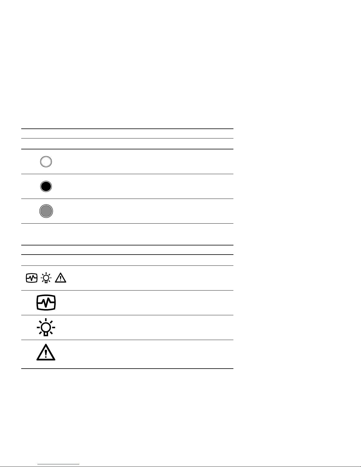
Status LED Symbols
LED is OFF.
LED is O
N.
LED is F
LASHING
Table 2 is a list of the symbols that appear on devices and in this publication.
Table 2 Device Symbols
Enclosure Symbols
Enclosure LED label
(Symbol definitions follow.)
Enclosure Status (green)
Enclosure Power (green)
Enclosure Fault (amber)
NOTE: This signal indicates there is an enclosure fault. This does not
indicate that there is possibility of personal injury and is therefore NOT a
WARNING.
Page 13
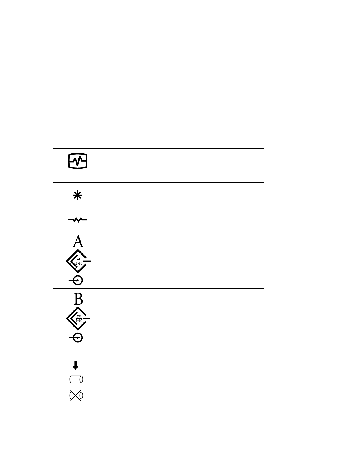
EMU Symbols
I/O Module Symbols
About This Guide xiii
Table 2 Device Symbols (Continued)
EMU Status LED symbol (green)
Power Statu s (ON) LED (green)
Terminator Status LED (green)
SCSI Bus A Connector
Ultra2 SCSI Bus
Input Connector
ISCSI Bus B Connector
Ultra2 SCSI Bus
Input Connector
Drive LED Symbols
Drive Activity LED
Drive Online LED
Drive FAILURE LED
Page 14

xiv Compaq Enclosure 4200 Family LVD Disk Enclosure User Guide
Related Documents
Table 3 lists publications that contain additional informati on relevant to the LVD disk enclosure
products.
Table 3 Related Publications
Publication Title Part Number
Compaq StorageWorks
Disk Enclosure RETMA Rack Mounting Kit Installation Card
Compaq StorageWorks
Disk Enclosure RETMA Rack Mounting Template
Hot-Pluggable Wide-Ultra2 SCSI Hard Drives Installation Card
127430-001
102943-001
386195-001
Compaq StorageWorks
Replacing a Disk Enclosure Environmental Monitoring Unit Installation Guide
Compaq StorageWorks
Replacing a Disk Enclosure Power Supply Installation Guide
Compaq StorageWorks
Replacing a Disk Enclosure Ultra2 SCSI I/O Module Installation Guide
Compaq StorageWorks
Replacing a Disk Enclosure Variable Speed Fan Installation Guide
Compaq StorageWorks
Tower Model 4200T-Series User Guide
148455-001
148454-001
148453-001
148452-001
122942-001
Page 15

Chapter 1
Introducing the Enclosure
This chapter describes the StorageWorks Enclosure 4200 family of low voltage
differential (LVD) disk enclosures (see Figure 1–1 and Figure 1–2). These enclosures
support Wide-Ultra and Wide-Ultra 2 small computer system interface (SCSI )
protocols. The internal bus supports only LVD drives. The external bus (the enclosure to
the host controller bus) support s either Wide-Ultra2 (LVD) and or Wide-Ultra
single-ended (SE) SCSI protocols. The information in this publication is based on using
the Wide Ultra2 LVD SCSI protocol, the most ef ficient means of transferring data.
Figure 1–1. 14-drive enclosure
CXO6854A
Page 16

1–2 Compaq StorageWorks Enclosure 4200 Family LVD Disk Enclosure User Guide
CXO7082A
Figure 1–2. Disk enclosure (rear view)
Disk Enclosure Features
The Model 4214- and Model 4254-series enclosures support fourteen, 1-inch, 3.5-inch
form factor hard disk drives or drive blanks. Thes e en cl o s ur es are available in eith er a
rack mountable version (4214R) or in a tower version (4214T). A rack (cabinet) mounted
enclosure requires a RE TMA 3U vertical opening (5.25-i nches) where a “U” is 1.75
inches.
CAUTION: To ensure proper cooling, all drive bays must have either a drive or drive
blank installed.
The enclosure provi des s everal features, including:
■ Hot-pluggable drives, envir onmenta l monitoring un i t (EMU), blowers, and power
supplies are replaceable without stopping SCSI bus data transfers.
NOTE: An element with a port colored latch, tab, or handle is hot pluggable.
Pluggable I/O module and SCSI bus cabl es require stopping all data trans f ers , but do
■
not require removing power before replacing.
■ Depending upon the host controller, the I/O module is capable of supporting
Wide-Ultra2 SCSI (LVD) or Wide-Ultra SCSI (SE) bus operations.
Page 17

SCSI Buses
Introducing the Enclosure 1–3
These encl o su r es do not support the following storage devices:
■ Tape drives
■ CD-ROMs
■ Solid state drives
The enclosure has guides that ensure the drives, EMU, I/O module , and power supplies
(the enclosure elements) align and properly mate with the backplane con nec tors. A
blower guide post on the blower ensures that the blower properly mates with the power
supply. The elements an d th e metal enclosur e provid e electromagnetic interference
(EMI) suppression and control air flow within the enclosure.
The enclosure supports only Wide-Ultra2 SCSI, wide (16-bit), internal LVD buses.
Depending on the host int erfac e, the e xte rnal SCSI b us , the b us from the I/O modul e to the
host can be either Wide-Ultra or Wide-Ultra2, LVD or SE. The SCSI bus type determines
the length of this bus, and therefore, the maximum cable length. The standard Compaq
cable length of 12 ft (3.7 m) ensures satisfactory operation. As for all SCSI buses, the
shorter the cabl e, the mo r e efficient the bus ope ration .
Each enclosure has two internal SCSI buses, with half of the devices on each bus. The
single-b us I/O modu le place s al l the devices o n a si ngle-b us of eit her 10 or 14 devices. The
dual-bus I/O module maintains two internal buses with either 5 or 7 devices on each bus.
High Availability
The high availabil ity features of t he e nclosure are a function of the blowers and the power
supplies.
Variable Speed Blowers
All enclosures have two variable speed blo w ers. In all configurations, the failure of one
blower automatically causes the other blower to operate at a high speed. This ens ures that
the failure of a single b lower does not di sable the enclosure .
NOTE: The maximum bus length is the inverse of the transmission speed. The faster the
transmission rate, the shorter the bus length. For more information about the supported SCSI
bus lengths, see Chapter 3.
Page 18

1–4 Compaq StorageWorks Enclosure 4200 Family LVD Disk Enclosure User Guide
Power Supplies
In a single pow er s upply configura tion, the fail ure of a po wer supply disabl es the
enclosure. Use the optional redundant power supply configuration to prevent this. In this
config uration, the failure of a single power sup ply or blower does not disable the
enclosure.
Data Integrity
Data inte grity could b e c ompromised if dat a transfers occ ur when there is no DC powe r to
the I/O module or the drives, To avoid inducing error s, the power pins on thes e el ements
are longer than th e data pins. This ensures that power is always present when a data
transfer occurs.
Status Monitoring and Display
The major status monitoring capabilities of these enclosures include:
■ Displaying the enclosure status on the enclosure LEDs
■ Displaying the element status on t he power supply, EMU, drive, and I/O module LEDs
■ Detecting the installation of a blo w er, power suppl y, disk drive, or I/O module
■ Detecting the blower removal of a blower, power supply, disk drive, or I/O module
■ Sensing enclos ure te mperatures
■ Sensing power sup ply voltage, curre nt, and total po wer
Enclosure Layout
The physical la yout of the enclosure is th e same in a rack or a tower. The dri ves mount in
the bays in the front of the enclosure. These bays are numbered from the left (bay
the right (see Figure 1–5 and Figure 1–3). The common method of referring to a drive is
by the bay number. The drive in bay
forth.
CAUTION: There is no direct correlation between the bay number and SCSI bus ID.
The SCSI bus IDs are a function of the bus type (single or dual) and the number of
drives See Chapter 3 for SCSI bus IDs.
1
is drive 1, the drive in bay 8 is drive 8, and so
1
) to
Page 19

1
3
5
2
4
Figure 1–3. 14-drive enclosure bays
7
9
6
8
11
10
12
13
14
15
CXO6728A
Introducing the Enclosure 1–5
1—-
Drive Bays
?
— Enclosure Stat us LEDs
(see Figure1–4)
Page 20

1–6 Compaq StorageWorks Enclosure 4200 Family LVD Disk Enclosure User Guide
The enclosure status LEDs are located in the front, lower-right corner of the enclosures
(see
Figure 1–4).
Enclosure Status (FLASHING)
Enclosure Power (O
Enclosure Fault (O
Figure 1–4. Enclosure status LEDs
N)
FF)
The I/O module, po wer supplies, blo w ers, EMU, and cables mount in the rear of the
enclosure (see Figure 1–5).
1
EMU
2
Blower 1
3
Power Supply Bay 1, or
Blower Mounting Assembly
4
Blower 2
5
Power Supply Bay 2
6
Single- or Dual-Bus I/O
1
Module
1
2 3 4 5 6
CXO6979A
Figure 1–5. Rear -mounted elements
1. In a singl e power supply configuration, the blower mount s on the blow er mounting assembly.
Page 21

Major Elements
The elements required fo r p roper oper ation of each enclosure include:
■ An EMU
■ Two power supplies, or
1 power supply a nd 1 blower mounting asse mb ly
■ Tw o b low ers
■ A single- or a dual-bus I/ O modul e
■ A dis k drive or disk driv e blank in each bay
Element Functions
A full description of the individual elements an d their functions can be found in the
individual chapters.
Element Replacement
The methods used to replace an element depend upon the following factors:
■ Coul d element replacement affect SCSI bus operation?
When the element being rep laced does not interrupt data transfer nor affect the
operat io n of an o th e r el em en t, the element is “hot-pluggable.”
Introducing the Enclosure 1–7
If replacement of the element, could affect data transfers or the operation of another
element, the element replace me nt method is “pluggable.”
■ Are there any personal safety issues involved?
Whenever there is an issue involving personal safety, such as an electrical hazard, then
the element replacemen t r equires stopping all data t r ansfers the SCSI b u s and
removing power from the enclosure.
■ Are special tools or techniques required?
When element replacement can be completed without employing special tools or
techniques, then the element is a customer replaceable unit (CRU).
When special tool s or techniques are required to replace an element, then the unit is a
field repla ce able unit (FRU). Only qualified, Compaq field service personnel are
authorized to replace FRUs. There are no FRUs for these products.
Table 1–1 identifies the rep lacement method for each el ement.
Page 22

1–8 Compaq StorageWorks Enclosure 4200 Family LVD Disk Enclosure User Guide
Tab l e 1 –1 CRU Replacement Methods
Element Method
Drive
Hot-pluggable
EMU
Blower
I/O Module
Power Supply–Dual
Power Supply–Single
SCSI Bus Cables
1. Replacing an I/O module requires stopping all data transfers.
2. In a singl e power supply configuratio n, the enclosure is disabled when th e power
supply fails.
3. Connecti n g or disconnecting a SCSI bus cable re quires stopping all dat a transfers.
Hot-pluggable
Hot-pluggable
Pluggable
Hot-pluggable
No Power Applied
Pluggable
1
3
2
Page 23

With the enclosure ins talle d in a a r ack or tow er it is necessary t o :
1. Connect the SCS I bus cables.
2. Apply power.
3. Verify proper operation.
Connecting the SCSI Bus Cables
Connecting the enclosure to a host adapter or S CSI bus controll er is si mply a matter of
connecting cables to the I/O module. All I/O modul es have 68-pin, very high density
cable int e rco n nect (VHDCI) connectors.
Chapter 2
Starting the Enclosure
Figure 2 –1 shows the cable connectors for a single-bus configuration. Figure 2–2 sh ow s
the connectors for a dual-bus configuration.
CAUTION: Connecting or disconnecting a SCSI bus cable while data is being
transferred causes the loss of data.
To prevent errors, always stop all data transfers on the SCSI bus before connecting or
disconnecting a cable.
Page 24

2–2 Compaq StorageWorks Enclosure 4200 Family LVD Disk Enclosure User Guide
3
1
2
3
CXO7062A
SCSI Bus A connector
Figure 2–1. Single-bus I/O module cable connector
Page 25

Starting the Enclosure 2–3
.
2
SCSI Bus A connector
4
SCSI Bus B connector
1
2
3
4
CXO7063A
Figure 2–2. Dual-bus I/O module cable connectors
The maximum cable length is a function of the bus type (LVD or SE). See Table 2–1 for
the maximum Compaq supported SCSI bus cable lengths.
Table 2–1 Enclosure–Host Controller Maximum Cable Lengths
Bus Type Speed Cable Length
LVD Bus
Wide Ultra SCSI
Wide Ultra2 SCSI
Single-Ended Bus
Wide Ultra SCSI
40 Mb/s 12 m (39.4 ft)
80 Mb/s 12 m (39.4 ft)
40 Mb/s 3.7 m (12 ft)
Page 26
2–4 Compaq StorageWorks Enclosure 4200 Family LVD Disk Enclosure User Guide
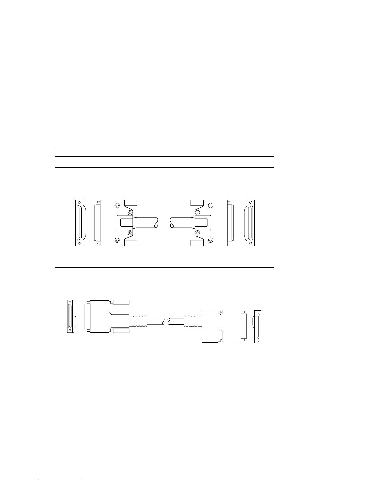
Table 2–2 describes the compatible host controller to LVD disk enclosure cables.
Table 2–2 Drive Enclosure—Host Controller SCSI Cables
Description Lengt h
SCSI Cable—68-pin VHDCI to 68-pin VHDCI
68-conductor SCSI cable with:
2—VHDCI straight male connectors with thumb screws.
SCSI Cable—68-pin VHDCI to 68-pin VHDCI
68-conductor SCSI cable with
2 Vertical Offset VHDCI straight plug connectors with jack screws
3 m (9.8 ft)
CXO5702B
3.7 m (12 ft)
CXO6954A
Page 27

Starting the Enclosure 2–5
Table 2–2 Drive Enclosure—Host Controller SCSI Cables (Continued)
Description Lengt h
Adapter Cable—68-pin High Density to 68-pin VHDCI
68-conductor SCSI cable with
1 High-Density straight plug connector with jack screws
1 Vertical Offset VHDCI straight plug connector with jack screws
3.7 m (12 ft)
CXO6955A
Page 28

2–6 Compaq StorageWorks Enclosure 4200 Family LVD Disk Enclosure User Guide
Tab l e 2 –3 Installing SCSI Bus Cables
1. Stop all SCSI bus data transfers.
2. Align the D-shaped cable connector with D-shaped I/O module connector
1
2
3
3. Firmly seat the cable connector on the module connector.
4. Finger tighten the thumbscrews to fully seat the connector.
5. Restart data transfers over the SCSI bus.
Applying Power
There are no disk encl osure power control switches. Connecting an AC po wer cord from a
power source to the power supply is all that is required. When a power supply has an AC
input, it develops and distributes DC voltages within the enclosure.
3
CXO7062A
Page 29

Verifying Operation
Elements begin operating when power is applied. Ch ec k the en closure status LEDs in the
front, lower rig ht corne r (see Figure 2–3). If the display is not exactly as s ho wn, the re is an
element error con dition. Check the drive and enclosure status LEDs on the front and the
EMU, power suppli es , blowers, and I/O module status LEDs on the rear (see Figur e 2–4)
to determine the defective element.
NOTE: Either of drive displays in Figure 2–3 indicate a properly functioning disk.
Starting the Enclosure 2–7
Figure 2–3. Typical front status LEDs
CXO6919B
Page 30

2–8 Compaq StorageWorks Enclosure 4200 Family LVD Disk Enclosure User Guide
Figure 2–4. Rear status LEDs
CXO6982B
Page 31

Chapter 3
I/O Modules
This chapter discusses the operation and function of the single- (see Figure 3–1) and
dual-bus (see Fi gure 3–2) LVD disk enclosure plugga ble I/ O modules (c ommonly re ferred
to as the “module”). The first part discuss es the general and common features of all
modules. Individual sections discuss the single-bus and dual-bus module functions and
features.
Figure 3–1. Single-bus I/O module Figure 3–2. Dual-bus I/O module
CXO7054A
CXO7053A
Page 32

3–2 Compaq StorageWorks Enclosure 4200 Family LVD Disk Enclosure User Guide
Common Features
The followi ng features are common to both the si ngle- and the dual-bus I/O modules.
These modules are pluggable elements. Replacing ei ther I/O modules or the cables
requires stopping all data transfers to prev ent the loss of data.
CAUTION: To prevent the loss of data it is necessary to stop all data transfers when
connecting or disconnecting a SCSI bus cable or removing and installing an I/O
module.
Each enclosure requires an I/O module for operation with a wide (16-bit) Ultra2 LVD
SCSI controller. The module is the CRU that connect s the enclosure to th e hos t controller
through a 68-pin, VHDCI connector and a SCSI bus cable. This module can support a
maximum of 14 drives in a single enclosur e or on a single-bus.
Each enclosure has two SCSI buses. Half of the drive bays are on each bus. The I/O
module type (single- or dual-bus) determines the enclosure bus configuration.
■ When using the single-bus I/O module with al l the addressable devices on the sa me
bus (SCSI b us A). This configuration requires one controller or host adapter.
■ When using the dual-bus I/O module half the addressable devices are on SCSI bus A
and the other half are on SCSI Bus B. This configuration requires two controllers or
host adap t ers .
See “Single-Bus SCSI Address Maps” and “Dual-Bus SCSI Address Maps” for
information about the drive SCSI bus addresses.
Configuring the Enclosure SCSI Bus
Installi ng an I/O module automatically configure s the enclosure for eithe r single- or
dual-bus operation. Such installation automatically changes the drive SCSI bus IDs.
CAUTION: To avoid the possibility of losing data, always backup data before installing
a different type I/O module.
Page 33

Module Power Protection
A +5 VDC sensor in the module detec ts overcurr ent conditions. Should this error occur,
the sensor disconnects the volta ge from the module and the power LED is O
disables the modul e until one of the following conditions occurs:
■ The overcurrent condition no longer exists.
■ The defective module is replaced.
SCSI Bus Termination
A SCSI bus is defined by two bus terminators. The external bus has termina tors on the
controller and on the module. Each internal bus has a termina tor on the modu le and on the
backplane. The module connects th e external bus and the internal b u s together. On each
module, there is a green LED (see Figure 3–5) that defines the status of the module
external bus terminator as ei th er termi n ated or unterminated.
I/O Modules 3–3
FF. This
When the module exte rnal SCSI bus is unterminated (the ass ociated LED is O
cannot be transferred.
FF) data
Page 34

3–4 Compaq StorageWorks Enclosure 4200 Family LVD Disk Enclosure User Guide
Status LEDs
The green LEDs display the st atus of the external SCSI bus terminators and the I/O
module power.
Terminator LED
The I/O module label ide ntifies the SCSI bus LED with a letter (A or B)
above the LED and the terminator symbol below the LED.
■ The LED is ON when the external SCSI bus is terminated and usable.
■ The LED is OFF when the external SCSI bus is unterminated, and therefore unusable.
Power LED
This LED displays the status of the module power . The module label has an
asterisk symbol adjacent to power LED.
■ The LED is ON when the module +5 VDC is correct.
■ The LED is OFF when the module +5 VDC is incorrect or miss ing.
SCSI Bus Connectors
The I/O module label ide ntifies each 68–pin, VHDCI SCSI bus connector wit h one of the
labels shown in Figure 3–3 and Figure 3–4:
Figure 3–3. SCSI Bus A connector symbol Figure 3–4. SCSI Bus B connector symbol
Page 35

Replacing an I/O Module
To replace an I/O module, you must complete the proce dures outlined in Chapter 6,
“Replacing CRUs.”
Single-Bus Module
This section describes th e c omponents and unique features of the single-bus module. T his
module (see Figure 3–5) has one VHDCI connector and two LEDs.
1
1
Latch
2
Status LEDs
EFT– Power
L
RIGHT–SCSI Bus A
termination status
3
SCSI Bus A connector
I/O Modules 3–5
3
Figure 3–5. Single-bus I/O module components
2
CXO7062A
Page 36

3–6 Compaq StorageWorks Enclosure 4200 Family LVD Disk Enclosure User Guide
Single-Bus I/O Module Status Displays
Table 3–1 describes the single-b us I/O module LED status disp lays.
Tab l e 3 –1 Single-Bus Status LED Displays
LED is ON LED is OFF LED is FLASHING
When the I/O module is operational, the display may be
SCSI bus is terminated (LED ON)
Module power present (LED O
When the I/O module is nonoperational, the display may be
SCSI bus is unterminated (LED OFF)
Module power present (LED O
N)
N).
No module power (All LEDs O
Module nonoperational
FF)
Single-Bus SCSI Address Maps
The module assigns a SCSI add r ess to each drive bay in the enclosure using a SCSI
address map (see Table 3–2).
Table 3–2 Single Bus SCSI Bus IDs
Bay 1234567891011121314
14–Disk Enclosure
SCSI
ID
00 01 02 03 04 05 08 09 10 11 12 13 14 15
Page 37

Dual-Bus I/O Module
This sectio n des cribes the unique fe atures and components of the dual-bus modul e. This
module (see Figure 3–6) is easily identifiable by the two VHDCI connectors and the three
LEDs.
1
2
3
1
Latch
2
SCSI Bus A connector
3
Status LEDs
EFT–Power
L
IDDLE—SCSI bus A
M
termination status
R
IGHT–SCSI bus B
termination status
4
SCSI Bus B connector
I/O Modules 3–7
4
Figure 3–6. Dual-bus I/O module components
CXO7063A
Page 38

3–8 Compaq StorageWorks Enclosure 4200 Family LVD Disk Enclosure User Guide
Dual-Bus I/O Module Status Displays
Table 3–3 describes.dual-bus I/O module status LEDs displays.
Tab l e 3–3 Dual-Bus Status LED Displays
LED is ON LED is OFF LED is FLASHING
When the I/O module is operational and the external SCSI bus is terminated, the display
may be:
Module power present (LED ON)
SCSI bus A terminated (LED O
SCSI bus B terminated (LED O
When the I/O module is operational and the external SCSI bus is unterminated, the
display may be:
Module power present (LED ON)
SCSI bus A unterminated (LED O
SCSI bus B terminated (LED On)
N)
N)
FF)
Module power present (LED O
N)
SCSI bus A terminated (LED On)
SCSI bus B unterminated (LED O
Module power present (LED O
Backplane Terminator A unterminated (LED O
Backplane Terminator B unterminated (LED O
FF)
N)
FF)
FF)
When the I/O Module is nonoperational, the display may be:
No module power (All LEDS OFF )
Module nonoperational
Page 39

I/O Modules 3–9
Dual-Bus SCSI Address Maps
The module assign s a SCSI address to each dri ve bay in the enclosur e us ing a SCSI
address map (see Table 3–4).
Tab l e 3 –4 Dual Bus SCSI Bus IDs
Bay 1234567891011121314
14–Disk Enclosure
SCSI
ID
00 01 02 03 04 05 08 00 01 02 03 04 05 08
SCSI Bus A SCSI Bus B
Page 40

Page 41

Chapter 4
Environmental Monitoring Unit
The Compaq Stor age Works Environment al Moni toring Unit, the E MU, ( see Figure4–1) is
an integral part of ever y Model 4200 series LVD enclosure. This element per forms several
functions, including monitoring the enclosure operat ion, detecting and indicating errors,
and displaying the EMU and enclosure status.
1
EMU stat u s LE D (g re en)
1
F
LASHING
—EMU Operational
O
N—Internal EMU problem
FF—Internal EMU problem
O
2
Tower LCD panel cable connector
1
For transferring error messages to
LCD panel.
Figure 4–1. Model 4200-series LVD disk enclosure EMU
1. When FLASHING rapidly, the EMU is operational and there is a single–ende d drive
insta lle d in th e en c lo su re.
2
CXO7131A
Page 42

4–2 Compaq StorageWorks Enclosure 4200 Family LVD Disk Enclosure User Guide
The EMU mounts in the bay at the left rear of the enclosure (see Figure 4–2).
1
EMU
Functions
1
Figure 4–2. Model 4200-series LVD disk enclosure EMU location
2 3 4 5 6
CXO6979A
The EMU functions includ e:
■ In conjunction with the I/O module, assigning device SCSI bus addresses
■ Monitoring the enclosure operation
■ Detecting and reporting errors
■ Displaying the EMU and enclos ure status
■ Controlling the LEDs
■ In conjunction with Compaq SCSI adapter or RAID controll er, implementing
enclosure services protocols to report status
The enclosure functions and operations t he EMU monitors include:
■ Temperature
■ Power Supplies
■ Blowers
■ Drives
■ EMU internal functions
Page 43

Status LEDs
Environmental Monitoring Unit 4–3
The EMU status LED (see Figure 4–1) displays the status of the EMU and notifies the
user when there is a single-ended drive installed. The thre e status LEDs (see Figure 4–3)
display the status of the EMU and the enclosure, the enclosure powe r, and an enclosure
fault.
EMU and Enclosure
LASHING)
Status (F
Enclosure Power
(O
N)
Enclosure Fault
FF)
(O
CXO7132A
Figure 4–3. Drive and Enclosure status LEDs
The EMU also monito rs the dri v e, power supply, and blower L EDs. The ope ration of thes e
LEDs are describe d in the individua l element chapters.
Page 44

4–4 Compaq StorageWorks Enclosure 4200 Family LVD Disk Enclosure User Guide
Temperature
The EMU monitors the internal temperature using enclosure mounte d sensors.
■ When the enclosure internal temperature i s 45 °C (113°F) or mor e, the E M U turns ON
the amber Enclosure Fault LED.
■ A power supply automatically shutdown if the interna l power supply temperature
exceeds 85°C (180°F).
■ When the Compaq Insight Manager (CIM) is installe d, it reports an alarm condition
when the ambient temperat u r e re ac h es 5 0°C (122°F).
NOTE: The internal enclosure temperature and the ambient temperature are not the
same. The ambient temperature is the air temperature in an area where the enclosure is
installed. It is also referred to as the enclosure intake air temperature, or room
temperature. The enclosure internal temperature may be significantly higher.
Fault Bus
The active enclosure mana gement services protocol is determined by the Compaq SCSI
adapter or the RAID controller attached to the enclosure. The fault bus is a protocol
supported by the EMU.
The Ultra2 SCSI bus co ntrolle rs and a dapters can co ntrol RAID subsystems , such as thos e
using StorageWorks Model 4200 LVD disk enclosures. Although the bus is a data
interchange facility it does not provide the feat ures necessary to permi t a co ntroller to
monitor enclos ure an d st orage device status. The fault bus provides this funct ion. The
LVD enclosure family and the EMU support the fault bus as described in the following
sections.
The LVD enclosure implementation of the fault bus consis ts of the enclosure status
(SHELF_OK), the device swap (SWAP L), and two fault signals (FAULT_DATA and
FAULT_CLK) signals. These signals provide the controller with the capability to
effectively monitor specific RAID storage subsystem faults. These fault signals can, in
conjunction with the EMU, control the device st atus LEDs to provide visual indicatio ns of
error conditions.
Enclosure Status Signal
This fault bus signal (SHELF_OK) changes state to indicate a change in either an
enclosure powe r supply or cooling blower status.
Page 45

This signal is asserted (high) when all the power supplies and blowers are oper ating
properly. Should any power supply or blower be operating outside of a specif i ed range thi s
signal level is low until the fault is corrected.
Device Swap Signal
This fault bus signal (SWAP) detects the removal or insertion of a storage device on a
SCSI bus caus ing the signa l to gene rate a logic lo w puls e. The SWAP signal for each SCSI
bus indica t es a ch an g e in th e st at u s of th e sto r a ge devi c es on th at bus.
Device Fault Signal
The EMU can control the device status LEDs in the following manner:
■ When the controller detects a device fault, it can cause the EMU to FLASH the spec ific
device status LED at a fast rate.
■ T he c ontr o ll er ca n ca use the EMU to FLASH a sp ecific de vi ce st atu s LED at a slow rate
to identify or “locate” a device.
Environmental Monitoring Unit 4–5
Replacing an EMU
To replace an EMU, you must co mpl ete the procedures outlined in Chapter 6, “Replacing
CRUs.”
Page 46

Page 47

Chapter 5
CXO6696A
Disk Drives
The enclosure supports Compaq hot-pluggable , Wide-Ultra2 SCSI, LVD disk drives. This
chapter descri bes the disk dri ve features, functions, and characte ristics.
The 14-disk enclo sure supports 1.0-inch, 3.5-inch form factor drives mounted in a carrier
Figure 5 –1.
CAUTION: Controlling airflow within the enclosure requires installing a disk
drive or a drive blank in each drive bay.
To avoid overheating, never remove more than 1 drive or drive blank from an
operating enclosure at the same time.
Figure 5–1. 1-Inch disk drive
Page 48

5–2 Compaq StorageWorks Enclosure 4200 Family LVD Disk Enclosure User Guide
Status Reporting
All drives have three status LEDs (see Figure 5–2) to define the operational status of the
driv e. T o determine the drive status you must observe all three LEDs ( see Table 5–1).
Drive Activity LED
This green LED F
synchronization with the other two LEDs
in response to the EMU locate
command.
Depending on the host controller, this
LED can either F
unison with On-Line LED when there is
SCSI bus activity.
This LED is O
activity.
On-line LED
When the +5 VDC is available and the
disk is properly installed, this green LED
is O
N. When these conditions are not
met, the LED is O
This LED F
with the other two LEDs in response to
the EMU locate command.
Depending on the host controller, this
LED can either F
unison with On-Line LED when there is
CXO6695A
SCSI bus activity.
Drive Failure LED
This amber LED F
synchronization with the other two LEDs
in response to the EMU locate
command.
Depending on the host controller, this
amber LED can F
controller detected error condition.
LASHES in
LASH by itself or in
FF when there is no bus
FF.
LASHES in synchronization
LASH by itself or in
LASHES in
LASH when there is a
Figure 5–2. Disk drive LEDs display
Page 49

Drive Status
The two g reen and one amber LEDs are either ON, OFF, or FLASHING. Since the status
LED displays are easily interpreted, they are the most commonly used indicators of dr ive
status. In some configurations, the host controller can control the status LEDs. The
symbols for these conditions are shown in Table 5–1.
Table 5–1 Drive LED Status Displays
LED is ON LED is OFF LED is FLASHING
Display Status Drive Replacement
When the drive is operational the display may be one of the following:
When this display occurs at initial statup it may mean:
The operational drive is not being accessed.
The drive status is one of the following:
■ The drive is a replacement drive to be rebuilt,
■ The drive is an inactive spare disk.
■ The drive is spinning up during POST.
■ The SCSI controller cannot control LED.
It should change within a few minutes, otherwise the drive is
nonoperational.
The operational drive is not being accessed.
Drive is being rebuilt or Array Capacity expansion in progress
O NOT REPLACE DRIVE
D
Do not replace drive
Disk Drives 5–3
The operational drive is not being accessed.
The drive is configured as part of an array
Drive selected using the Array Configuration Utility. Do not replace drive
The drive is operational and active.
The drive is configured as part of an array
Do not replace drive
Drive may be replaced
Page 50

5–4 Compaq StorageWorks Enclosure 4200 Family LVD Disk Enclosure User Guide
Table 5–1 Drive LED Status Displays (Continued)
LED is ON LED is OFF LED is FLASHING
Display Status Drive Replacement
The operational drive is being accessed. or spinning-up.
The drive status is one of the following:
■ Replacement drive to be rebuilt,
■ The drive is an inactive spare disk.
■ The drive is spinning up during POST.
■ The SCSI controller cannot control LED.
The operational drive is being accessed.
The drive status is one of the following:
■ Drive is being rebuilt
■ Array Capacity expansion in progress
The drive is operational and active
The drive is configured as part of an array.
When the drive is nonoperational, the display may be one of the following:
The drive is nonoperational.
There is no power to the drive.
Do not replace drive
Do not replace drive
Do not replace drive
Drive may be replaced
There is a drive error and the drive is not active.
Check the GUI for a definition of the problem.
Drive Power
Backplane overcurrent sensors monitor the +5 VDC and +12VDC drive voltages . When
there is a drive overcurrent condition the sensor disconnects the voltage from the drive.
This disable s the dri ve , ensu ring t hat no dat a is writ ten to i t. The dri ve i s dis abled un til one
of the following conditions occ urs:
■ The defective drive is replaced.
■ The overcurrent condition no longer exists.
Drive may be replaced
Page 51

Drive Blank
To maintain the proper enclosure airflow, there must be a drive or a driv e blank in each
driv e bay. The f unction of the dri ve blank Figure 5–1 is to control airflow within a bay.
Disk Drives 5–5
CXO6824A
Figure 5–3. 1-Inch drive blank
Page 52

5–6 Compaq StorageWorks Enclosure 4200 Family LVD Disk Enclosure User Guide
Replacing a Disk
To replace a disk, you must order a replacement using the spare part number (see Chapter
6, “Replaci ng CRUs”).
The disk replacement kit contains detailed replacement instructions.
CAUTION: Removing more than one disk dr ive at a time can cause the enclosure to
overheat. Never remove more than one disk drive at a time.
NOTE: Removing a drive from the enclosure affects the air flow in the enclosure. This can result
in an overheating condition that could affect disk reliability. Compaq recommends installing a
disk drive of equal or greater capacity, or a disk drive blank as soon as possible.
NOTE: For the latest information and instructions about Compaq hard drives, such as
compatibility and installation instructions, refer to the Technical Information area of the
following Compaq website:
http://www.compaq.com/products/servers/storage/enterprise-class.html
Page 53

Chapter 6
Enclosure Power and Cooling
This chapter describes the function and general operation of the enclosure power supply
and Blowers. See Figure 6–1 for major component locations.
1
1
6
5
Power Supply Element
2
AC Input Connector
3
Module Latch
4
Status blower LED
5
Blower Tabs
Figure 6–1. Power supply and blower assembly components
6
Blower Element
3
2
4
5
CXO6809A
Page 54

6–2 Compaq StorageWorks Enclosure 4200 Family LVD Disk Enclosure User Guide
Enclosure Power
The power supply and blower assem bly mount in the rear of the enclosure. The supply is
auto-ranging and operates on an A C input voltage of 100 to 240 VAC ±10% , 50 to 60 Hz
± 5% (90 to 264 VAC, 47 to 63 Hz).
The DC outputs of this supply are:
■ + 5.1 VDC for the EMU, I/O module, backplane, an d drives
■ +12.1 VDC for the drives.
■ +12.5 VDC for the blower.
The nominal output of each supply is 377W, with a peak output of 475W. Either power
config uration, single or dua l, can support an enclosure with a full complement of disks,
blowers, EMU, and I/O module.
■ A s ingle power supply, the standard configuration, supports seque ntial drive spin-up.
■ T he Compaq recommended dual po wer supply conf igurati on can support simultaneous
drive spin-u p .
The power supply circuitry provides protection against:
■ Overloads
■ Short circuits
■ T hermal protection against cooling system faults .
Power su pply st at u s an d d iagnos t i c in f o rm ation is r ep o r ted to the EMU wi th vol ta ge,
current, and temp erature signals.
See Appendix B, “for the enclosure power specifications.
Power Options
The enclosure can accommodate one or two power supplies. One power s upply is
sufficient to power the enclosure with a full complement of drives.
NOTE: Installing two power supplies, a redundant power configuration, eliminates the power
supply as a single point of enclosure failure. This is the preferred, high-availability configuration.
For complete power redundancy, each supply should be connected to a separate AC power
source.
Page 55

The blower mounting assembly is the e lem ent for mounting the second blower. This
element has no powe r circuitry. It does conta in a circuit board for processing signals to
and from the blower.
Temperature Sensing
The power supply uses the internal temperatur e of the supply to set th e speed of the
blower. The power supply blank can also set the blower speed. The higher the power
supply temperature, the faster the speed of the blower. Should the power supply
temperature e xceed a preset val ue, the power supply is shut down.
Blower Interface
The blower mounts on the rear of the power supply. A power supply connector is the
interface between the b lower and the enclosure. The interfac e signals in clude:
■ Blower speed control to the blower
■ Blower speed to the EMU through the powe r supply
■ Power supply high-s peed enable
■ Blower operating voltage
Enclosure Power and Cooling 6–3
Blowers
The power supply-mounted blowers cool the enclosur e by circulating air through the
enclosure and elements. The rate at which air moves, the airflow, determines the amount
of cooling. Th is airflo w is a function of blower speed (rpm). Thes e blower blowers, under
the control of the EMU or the associated power supply, can operate at multiple speeds.
This ensu res tha t w h en the enclosure temperature changes , the blowers ca n au tomati cally
adjust th e airflow.
Should a blower fail
of the operational blower to high speed. Simultaneously, the error condition is reported to
the user in several ways.
NOTE: The failure of the power supply 12.5 VDC circuit disables the associated blower.
1. Operating at too low a speed or stopped.
1
, EMU and power supply circuitry automatically increase the speed
Page 56

6–4 Compaq StorageWorks Enclosure 4200 Family LVD Disk Enclosure User Guide
Status Reporting
The green status LED on the blower displays the status of either the power supply or the
blower. See Table 6–1 for definitions of the LED displays.
Tab l e 6 –1 Power Supply and Blower Status Displays
LED Status
Operational Status
Both the power supply and the blower are operational.
The EMU is locating either the power supply or the blower.
Nonoperational Status
Either the power supply or the blower is nonoperational.
When there is a blower problem, the other blower runs at high-speed.
Replacing a Power Supply or Blower
To replace a power supply or blower, you must order a replacement using the spare part
number (see Chapter 7, “Replacing CRUs”).
CAUTION: As long as there is one operational power supply, you can replace a
defective supply without stopping data transfers. This is true whether the power
supply has failed or is failing.
Each power suppl y or blower replac ement kit contain s detailed replacement instructions.
Page 57

Each replacement CRU kit contains detailed replacement instructions. This chapter
describes the gene ral replacement procedures.
Ordering a CRU
To order a CR U, you must use the Compaq spare part numb er.This number is located in
the upper-right corner of the product labe l (see Figure 7–1).
Chapter 7
Replacing CRUs
Figure 7–1. Typical CRU product label
This the firs t six ch ar ac ters of the p ar t nu m b er id entify th e CRU. The last th re e d efin e th e
revisi on level.
ESD Protection
When you replace a CRU, you must take precautions to prevent the possibility of
electrostatic discharge (ESD) damaging sensitive electronic items.
1. Always transport a nd store CRUs in a sta tic-safe contai ner.
CXO7083A
Page 58

7–2 Compaq StorageWorks Enclosure 4200 Family LVD Disk Enclosure User Guide
2. Do not remove the CRU from the static-free container until you are ready to install it.
3. Avoid touc hing the CRU connector pins, lead s, or circ uitry.
Basic Replacement Procedures
The procedures in Table 7–1 apply to all the CRU replacement proc edures.
CAUTION: The hot-pluggable power supplies, blowers, EMU, and drives DO NOT
require halting all data transfers on the SCSI bus.
Replacing an I/O module or a SCSI bus cable always requires halting all data transfers
on the SCSI bus.
Table 7–1 Common Replacement Procedures
1. Always transport and store CRUs in a static-safe container.
Before starting the replacement procedure
CAUTION: To prevent ESD damage, never touch the CRU connector pins, leads, or
circuitry.
2. Remove the defective CRU from the enclosure.
3. Remove the replacement CRU from the static safe container and verify that it is a compatible
replacement (refer to Figure 7–1).
4. Align the CRU with the enclosure guide slots.
5. Slide the CRU into the enclosure until it is against the backplane connector.
6. Fully seat the CRU in the enclosure and verify that if operating properly.
After replacing the CRU
7. Place the defective CRU in the static safe container for shipment.
Page 59

Initial Installation
When you are installing an enclosure in a rack or tower you must observe the following
warning.
WARNING: An assembled enclosure (all elements installed) weighs more than 65 lb
(29.5 kg). Moving the assembled enclosure requires a minimum of two individuals.
To safely and easily install the enclosure requires removing the drives, power supply
and blowers, EMU, and I/O module. This reduces the enclosure weight to
approximately 24 lb (11.3 kg). Even though a single person can lift this weight, the
physical size makes it very difficult to install.
Compaq requires a minimum of two individual to install an empty enclosure in a rack
or tower.
The handles cannot support the weight of the enclosure. Only use these handles to
position the enclosure in the mounting brackets. DO NOT use the handles to lift the
enclosure.
Use the proc edures in the fo llowing sections to rem ove al l the elements to make the
enclosure easier to handle. Once the enclosure is mounted you can replace the elements.
Replacing CRUs 7–3
Page 60

7–4 Compaq StorageWorks Enclosure 4200 Family LVD Disk Enclosure User Guide
Replacing a Drive
If a disk driv e fa ils, you must repl ace it with a dri ve or a dri ve bl ank usi ng the proc edure in
Table 7–2.
NOTE: For the latest information and instructions about Compaq hard drives, such as
compatibility and installation instructions, refer to the Technical Information area of the
following Compaq website.
http://www.compaq.com/products/servers/storage/enterprise-class.html
CAUTION: Removing more than one disk dr ive at a time can cause the enclosure to
overheat. Never remove more than one disk drive at a time.
Removing a drive from the enclosure affects the air flow in the enclosure. This can
result in an overheating condition that could affect disk reliability. Compaq
recommends installing a disk drive of equal or greater capacity, or a disk drive blank
as soon as possible
Table 7–2 Installing a Drive
1. Press the Ejector button 1 in and pivot the Release Lever
1
2
2. Pull out on the drive until it is disconnected from the backplane connector.
DO NOT REMOVE THE DRIVE FROM THE ENCLOSURE WHILE THE MEDIA IS ROTATING.
2
to the full, open positi ons.
CXO6826A
Page 61

Replacing CRUs 7–5
Table 7–2 Installing a Drive (Continued)
3. When you are sure that the disk is no longer spinning, remove the drive from the enclosure.
4. Insert the replacement drive or the drive blank part-way into the until it is against the backplane
connector
5. To install a drive blank, press it firmly in to seat it in the connector
2
6. To install a drive, push in on the drive while pivoting the Release Lever
position.
to the full upright
7. Push the Release Lever in until it engages the Ejector button
8. Observe the drive status LEDs (see Chapter 6) to ensure the replacement drive is functioning
properly.
1
.
Page 62

7–6 Compaq StorageWorks Enclosure 4200 Family LVD Disk Enclosure User Guide
Replacing the Variable Speed Blower
NOTE: Removing a blower does not change the airflow within the enclosure. However, do not
remove a blower until the replacement blower is available.
Complete the procedures in Table 7–3 to replace a variabl e spee d blower.
Table 7–3 Blower Replacement Procedure
WARNING: The blower blades rotate at a high speed and do not stop immediately
when power is removed. Avoid touching the rotating blades when removing the
blower.
1. Remove the blower from the power supply by pushing in on the two blower tabs 1 and while
pulling the blower element to the rear.
1
1
CXO6852A
Page 63

Replacing CRUs 7–7
Table 7–3 Blower Replacement Procedure (Continued)
CAUTION: Pressing on the center section of the blower 3 can damage the
blades. Only press on the outer shroud when installing the blower.
2. Align the blower guide post 2 with power supply connector 1. Slide the blower into blower base
4
until the tabs
1
snap into place.
4
2
4
3
CXO6853A
3. The following are indications that the replacement blower is operating properly.
■ The blower starts operating immediately.
■ The blower LED is O
N.
Page 64

7–8 Compaq StorageWorks Enclosure 4200 Family LVD Disk Enclosure User Guide
Replacing the EMU
NOTE: Removing an EMU significantly changes the airflow within the enclosure. Therefore,
always replace it as soon as possible.
The basic procedure for replacing an EMU is the same regardless of the system.
Complete the procedures in Table 7–3 to replace an EMU.
Table 7–4 EMU Replacement Procedure
1. Grasp the EMU handle and pull the EMU out of the enclosure.
2. Insert the replacement EMU in the enclosure.
3. Press the EMU firmly in to seat it in the connector
4. The EMU should start operating immediately.
CXO6911A
Page 65

Replacing a Power Supply
CAUTION: Removing a power supply significantly changes the airflow within the
enclosure. The system could shutdown unless the power supply is replaced within 5
minutes.
NOTE: Replacement power supply assemblies do not include a variable speed blower.
Therefore you must remove the operational blower from the defective power supply and install
it on the new supply before you remove the defective power supply.
Complete the procedures in Table 7–3 to replace a power supply.
Tab l e 7 –5 Power Supply Replacement Procedure
1. When you are replacing the supply in a single power supply configuration before it has failed, you
must stop all data transfers.
2. Disconnect the AC power cord from the defective supply.
WARNING: The blower blades rotate at a high speed and do not stop immediately
when power is removed. Avoid touching the rotating blades when removing the
blower.
Replacing CRUs 7–9
3. Remove the operational blower from the defective power supply by pushing in on the two blower
tabs
1
and while pulling the blower element to the rear.
1
1
CXO6852A
Page 66

7–10 Compaq StorageWorks Enclosure 4200 Family LVD Disk Enclosure User Guide
Tab l e 7 –5 Power Supply Replacement Procedure (Continued)
CAUTION: A Pressing on the center section of the blower
press on the outer shroud when installing the blower.
3
can damage the blades. Only
4. Align the blower guide post 2 with power supply connector 1. Slide the blower into blower base
4
until the tabs
1
snap into place.
4
2
4
3
CXO6853A
Page 67

Replacing CRUs 7–11
Tab l e 7 –5 Power Supply Replacement Procedure (Continued)
5. While lifting up on the module latch 3, grasp the blower element shell 6 and pull the power
supply to the rear.
1
6
5
2
CAUTION: Pressing in on the center section of the blower shroud can damage the blower
blades. To avoid damaging the blower, only press on the outer portion of the blower shroud.
6. While lifting up on the module latch 3, push in on the power supply 1 and the outer blower
6
shroud
7. Press the module latch down to secure the supply in the enclosure.
8. Connect the AC power cord and observe the power supply for proper operation.
■ The blower starts operating immediately.
■ The blower LED is O
■ The blower on the other supply is no longer be operating at high-speed.
until it is fully seated in the enclosure
N.
4
3
CXO6809A
Page 68

7–12 Compaq StorageWorks Enclosure 4200 Family LVD Disk Enclosure User Guide
Replacing the I/O Module
CAUTION: Interrupting the SCSI bus by replacing an I/O module could cause the loss
of data. Therefore, you must stop all SCSI bus data transfers before replacing a
module.
You must stop transfers on both SCSI buses when the enclosure is configured for dual
bus operation.
NOTE: Removing an I/O module significantly changes the airflow within the enclosure.
Therefore, always replace it as soon as possible.
The basic pr ocedure for r eplacing an I /O modul e is the s ame re gardle ss type. Comple te th e
procedure in Table 7–3 to replace an I/O module.
Table 7–6 I/O Module Replacement Procedure
1. After backing up the stored data, stop all data transfers.
2. Stop all transfers on the SCSI bus.
3
3. Disconnect the SCSI bus cable from the module connector
For a dual-bus I/O module, label the cables as remove them.
4. While grasping the module handle, press down on the module latch
the enclosure.
1
2
3
CXO7062A
.
1
and pull the module out of
Page 69

Replacing CRUs 7–13
Tab l e 7 –6 I/O Module Replacement Procedure (Continued)
5. Slide the replacement module into the enclosure.
1
6. While grasping the module handle, press the module latch
enclosure until it is fully seated.
7. Connect the cable connector to the same connectors (see Step 2).
8. Activate the SCSI bus and observe the LEDs to verify that the module is functioning properly.
down and push the module into the
Page 70

Page 71

FCC Class B Certification
This equipment has been tested and f ound to comply with the limits for a Class B digital
devi ce, pursuant to Part 15 of the FCC rules. These limits are designed to provide
reasonable prot ection against harmful interference in a residential installation.
Any changes or modifications made to this equipment may void the users authority to
operate this equipment.
This equipment generates, uses, and can radiate radio frequency energy and, if not
installed and used in accordance with the instructions, may cause harmful interference to
radio communicati ons. Ho we ve r , the re is no gua rantee that interfe rence will not oc cur in a
particular installation. If this equipment does cause harmful interference to radio or
television reception, which can be determined by turning the equipment off and on, the
user is encouraged to tr y to cor rect the interferenc e by one or more of the follow ing
measures:
Appendix A
Regulatory Notices
■ Reorient or relocate the receiving antenna.
■ Increase the separation between the equip ment and recei ver.
■ Connect the eq ui p m e nt into an ou t le t on a circu i t di ff er en t from tha t to wh i ch th e
receiver is connected.
■ Consult the dealer or an e xperienced radio/TV technician for help.
Page 72

A–2 Compaq StorageWorks Enclosure 4200 Family LVD Disk Enclosure User Guide
Country-Specific Certifications
Compaq tests all the electronic products for compliance with country-specific regulatory
requirements either as an individual item or as part of an assembly. The produc t label (see
Figure A–1) specifies the re gulations with which the product complies.
NOTE: Elements without an individual product certification label are qualified as part of the next
higher assembly (for example, enclosure, rack, or tower).
CXO7084A
Figure A–1. Typical enclosure certification label
NOTE: The certification symbols on the label depend upon the certification level. For example,
the FCC Class A certification symbol is not the same as the FCC Class B certification symbol.
Page 73

This appendix defines the physical, environmental, and power specifications and the
environmental specifications of the disk enclosure and the elements.
Physical Specifications
WARNING: The weight of the disk enclosure with the elements installed
always requires at least two individuals to move it. Compaq recommends
using fork lifts or hand trucks to move an enclosure in its shipping container.
Appendix B
Specifications
Table B–1 defines the dimensio ns and weights of the enclosure. Table B–2 defines the
dimensions of th e EMU, blowers, I/O module , a nd power supply.
Page 74

B–2 Compaq StorageWorks 4200 Family LVD Disk Enclosure User Guide
Tab l e B–1 Disk Enclosure Physical Specification
Horizontal Orientation Vertical Orientation
Empty Installed Shipping Carton Shipping Carton and
Height
5.16 in (13.1 cm) 5.16 in (13.1 cm) 25.25 in (64.1 cm) 30.25 in (76.8 cm)
Pallet
Depth
Width
Weight
17.625 in (44.8 cm) 17.625 in (44.8 cm) 23.5 in (59.7 cm) 40.0 in (101.6 cm)
19.875 in (50.5cm) 19.875 in (50.5cm) 12.5 in (31.8 cm) 24 in (61 cm)
24 lb (11 kg) 68 lb (31 kg) 96 lb (44 kg) 108 lb (49 kg)
Table B–2 Element Physical Specifications
Vertical Orientation Horizontal Orientation
Installed Shipping Carton
Environmental Monitoring Unit (EMU)
Height
Depth
Width
Weight
Height
Depth
4.5 in (11.4 cm) 8.5 in (21.6 cm)
9.5 in (24.1 cm) 13.0 in (33.0 cm)
1.375 in (3.5 cm) 4.5 in (11.4 cm)
1.3 lb (0.6 kg) 2.3 lb (1.0 kg)
Variable Speed Blower (without power supply)
5.5 in (14.0 cm) 7.5 in (19.0 cm)
3.25 in (6.4 cm) 8.75 in (22.2 cm)
Width
Weight
6.25 in (15.9 cm) 8.0 in (20.3 cm)
1.0 lb (0.5 kg) 2.0 lb (0.9 kg)
Page 75

Height
Specifications B–3
Table B–2 Element Physical Specifications (Continued)
Vertical Orientation Horizontal Orientation
Installed Shipping Carton
I/O Module
4.5 in (12.7 cm) 8.5 in (21.6 cm)
Depth
Width
Weight
Height
Depth
Width
Weight
9.5 in (24.1 cm) 13.0 in (33.0 cm)
1.625 in (4.1 cm) 4.5 in (11.4 cm)
1.3 lb (0.6 kg) 2.3 lb (1.0 kg)
Power Supply (without blower)
4.5 in (12.7 cm) 11.5 in (29.2 cm)
9.5 in (24.1 cm) 16.75 in (42.6 cm)
6.25 in (15.9 cm) 13.0 in (33.0 cm)
4.0 lb (1.8 kg) 6.0 lb (2.7 kg)
Environmental Specifications
To ensure optim um prod uct operation you must maintain the operational environmental
specifications listed in Table B–3. Especially critical is the ambient temperature.
Table B–3 Operating Specifications
Ambient Temperature: 10°Cto+35°C(+50°Fto+95°F) with an average rate of change of 1°C/hour
maximum and a step change of 3°Cor less
Maintaining the optimum ambient temperature within the specified range ensures that the internal
operating temperatures supports disk drive manufacturer’s MTBF specifications.
Relative Humidity: 40% to 60% (noncondensing) with a step change of 10% or less (noncondensing)
Air Quality: Not to exceed a maximum of 500,000 particles, 0.5 micron or larger, per cubic foot of air.
Heat Dissipation: 1600 BTUs per hour
Page 76

B–4 Compaq StorageWorks 4200 Family LVD Disk Enclosure User Guide
When shipping this product, or placing it in sho r t term storage, Compaq recommends
maintaining the environmental conditions listed in Table B–4.
Tab l e B –4 Shipping or Short Term Storage Specifications
Ambient Temperature: –40°Cto+66°C (–40°F to +150°F)
Relative humidity: 10% to 80% noncondensing
Altitude: 15,240 m (50,000 ft)
Power Specifications
Table B–5 defines the AC and DC power specifications for the disk enclosure power
supplies.
Table B–5 AC and DC Power Specifications
AC Power Specifications
Minimum Nominal Maximum
Frequency (±5%)
47 Hz 50 to 60 Hz 63 Hz
Range
Voltage (±10%)
DC Power Specifications
Power
+5 VDC
Initial Voltage
Steady State Current
+12 VDC (Disks)
Initial Voltage
Steady State Current
+12.5 VDC (Blowers)
Initial Voltage
Steady State Current
90 VAC 100 to 240 VAC 264 VAC
Not Applicable 377 W 475 W
5.10 VDC +5.15 VDC 5.20 VDC
Not Applicable 20.0 A 28.0 A
12.13 VDC 12.25 VDC 12.37 VDC
Not Applicable 20.0 A 31.5 A
12.25 VDC 12.50 VDC 12.75 VDC
Not Applicable Not Applicable 2.5 A
Page 77

Glossary
3U A panel or enclosure that is 5.25 inches (133.35 mm) high.
AC Alternating c urrent. T he ab brev iatio n for a lternati ng current . DO NO T use
ac.
AC distribution The method of distributing AC power within a Stor ageWorks enclosur e,
tower, or rack (cabinet).
AC power supply See power supply.
ambient temperature The air temperature in an area where a system is installed. Also referred
to as rack or enclosure intake air temperature, or room temperature.
array controller See controller.
backplane An electronic printed circuit boar d that distributes bus, data , control,
power, and other signals to element connectors.
bay The physical location of an element, such as a disk drive, I/O module,
EMU, power supply, and so forth, in an enclosure. Each bay is numbered
to define its location within a single bus or a dual bus.
blower The variable speed air flow device, sim ila r to a fan, that creates air flow
within the enclosure to cool the elements.
bus ID See SCSI ID.
bus length T he length of a SCSI bus is the distance between two terminators.
cabinet A DIGITAL classic term for the StorageWorks enclosure with exterior
panels, and doo rs into whic h cable distr ib ut ion unit s, enc losu res, blo wers ,
and cables are mounte d to form a storage subsystem.
See also rack.
Page 78

Glossary–2 Compaq StorageWorks Enclosure 4200 Family LVD Disk Enclosures User Guide
carrier The container in whic h storage devic es are mounted to form CRUs.
Carriers are available in 3.5-inch form-factors for both low-profile
(1.0-in) and half-height (1.6-in) disks.
CE-Mark A European Economic Community (EEC) certif ication lab el that
identifies electroni c devices authorized for sale within member nations.
compatible device A storage device that has been tested in a specific enclosure and found to
be compatible
controller 1. A hardware–firmware device which manages communications on
behalf of host systems over the SCSI bus to devices. Controllers typically
diffe r by the type of interface to the host and provide functions beyond
those the devices support. 2. A stand-alone de vice which connects a host
adapter to the s tor age SCS I b us. Th is de vic e pro vid es RAID func tio nal ity,
typically has multiple SCSI bus ports, performs the lower layers of the
SCSI protocol, and normally operates in the initiator role .
See also array cont ro ll er.
controller enclosure A StorageWorks enclosure containing a controllers, cache modules,
power suppl ies , and blowers with either I/O modules or SCSI bus
connectors.
CRU Custom er replaceable unit. An enclosure el ement tha t th e custo mer can
replace with out using special tools or techniques.
customer replaceable
See CRU.
unit
device ID See SCSI ID.
differential SCSI bus A bus in whi ch the sig na l level is det er mined by the po t ential di ff er en c e
between two wire s. A differential bus is more robu st and less subject to
electrical noise than is a single-ended bus.
Dif f erenti al bus es may be eith er low voltage (LVD) or high voltage
(HVD).
disk A storage devic e s upporting random acce ss to fixed si ze b locks of data
disk array controller See controller.
disk enclosure A Compaq enclosure dedicated to supporting disk drives. Such an
enclosure includes the power supplies, blowers, I/O modules, and an
EMU.
Page 79

Glossary–3
drive blank A carri er th at is requ ir ed to con tr ol ai rfl o w wi thi n th e en cl osur e whenever
there is less than a full complement of disk drives in an enclosure. The
only function of a drive blank is to control airflow within the disk
enclosure.
dual bus An e nclosure that is configured with two independent buses con nected to
separate controllers.
dual power See redundant power configuration.
dual power
See redundant power configuration.
configuration
electromagnetic
See EMC.
compliance
electromagnetic
See EMI.
interference
electrostatic discharge See ESD.
element An object in an enclosure such as an EMU, power supply, disk, blower,
I/O module, and so forth. The object can be controlled, interrogated, or
described by the enclosure services process.
An object related to an enclosure. The object can be controlled,
interrogated, or described by the enc los ure services process.
EMC Electromag n etic Comp liance .
EMI Electromag n etic interference (EMI) is the impairment of a signal by an
electromagne tic disturbance
EMU Environmental monitoring unit. An element which monitors the sta tus of
an enclo su r e in cl u d in g the pow e r, air tem pe r at u r e, b lower statu s, an d so
forth. It detects problems and dis plays and reports these conditions to the
user and the controller. In some cases, corrective actions are
implemented.
enclosure A chassis containing a set of disk drives, power supplies, blowers, an
EMU, I/O modules, and so forth.
enclosure I/O module The enclosure element that connects the enclosure to a differential or
single-ended SCSI bus.
See also differential I/O module and single-ended I/O module.
Page 80

Glossary–4 Compaq StorageWorks Enclosure 4200 Family LVD Disk Enclosures User Guide
environmental
See EMU.
monitoring unit
ESD Electrostatic discharge (ESD). The disc harge of a potentia lly harmful
static electric voltag e whic h is a result of improper grounding.
fan See blower.
fault bus The StorageWorks implementation of an additional high-availability
subsystem monitoring capability for storage devices. This bus enables
controllers to illuminate the de vice status LED when the contro ller
detects a problem. In some configurations, thi s bus notif ies the controlle r
of the removal or replacement of a de vice.
FCC Federal Communications Commission. The federal agency responsible
for establishi ng standards and appr oving electronic devices wit hin the
United States.
form factor An industry dimens ional standard for 3.5-inch and 5.25-inch storage
devices. Device heights are specified as low-profile (1.0-inch),
half-height (1.6-in), and full-height (__-in)
FRU Field Replaceable Unit. A hardware element that can be replaced in the
field. This type replacement can require special training, tools, or
techniques. Therefore, these procedures are usually performed only by
customer service engineers.
GUI Graphical User Inte rface. A system that displays the status of a and
enables the use r to c ontrol the Stora geWorks subsystem. For ex ample , the
StorageWorks Command Console (SWCC).
high availability fault
See fault bus.
bus
host The prima ry or control lin g compu ter. bus extender, b us e xpande r , a dapte r ,
or controll er to which storage is attached.
host adapter A device that connects the host system I/O bus (for example, a PCI bus)
to the storage SCSI bus. A host adapter performs the lower layers of the
SCSI protocol and normally operates in the initiator role.
host computer See host.
Page 81

Glossary–5
host controller A device that connects the host system I/O bus (for example, a PCI bus)
to the storage SCSI bus. A host controller provides RAID functionality,
typically has multiple SCSI bus ports, performs the lower layers of the
SCSI protocol, and normally operates in the initiator role .
hot-pluggable An element that can be rep laced without removing power from the
enclosure or interrupting the transfer of data over the SCSI bus. Compaq
disk drives are hot pluggable.
See also pluggable.
NOTE: The array controller must support this replacement method.
I/O module The enclo sur e el em ent tha t is th e i nter fa ce to t he hos t or con tr ol le r. It m ay
include SCSI bus converter circuitry. I/O modules are bus specific (that is,
wide or narro w; SCSI, Ultra SCSI, or Ul tra2 SCSI; s ingle or dual b us; and
either single-ended or differential).
initiator A SCSI device (usually a host system) that requests an operation to be
performed by another SCSI device (a target).
input/output module See I/O modul e.
JBOD Just a bunc h of dis ks. A rack configuration composed of disk enclosures
without a controller enclosure.
just a bunch of disks See JBOD.
LED Light emittin g diode. A diode that illum inates to define the status. The
standard states are O
light emitting diode See LED.
low profile A storage device that ’s height is a maximum o f 1.0 inches.
low voltage differential See LVD.
LVD Low Voltage Differential. A bus in which the signal level is determined by
the potential difference between two wires.
maintenance terminal The operator terminal used to identify an HS-famil y controlle r, to enable
its host paths , to de fine its subs ystem configura tion, and to check its
status. The HS-family maintena n ce termin al interface is d esigned to
accept any termi nal co nforming to EIA–42 3. The main tenanc e ter minal is
only required to configure a stora ge subsystem and is not required for
normal operations.
N, OFF, or FLASHING.
Page 82

Glossary–6 Compaq StorageWorks Enclosure 4200 Family LVD Disk Enclosures User Guide
mean time between
See MTBF.
failures
modular carrier See carrier.
mounting brackets The brackets used for mounting StorageWorks enclosures in a cabinet.
mounting rail The surface of a rack on which panels mount. (Per EIA Standard
RS-310-C.)
MTBF Mean time between failures . T he time interva l (hours) which may be
expected between failures of operating equipment.
nonvolatile See NV.
NV Nonvolatile. A term used to describe memory, the contents of which
survive loss of power.
NVRAM Nonv o latile Random Access Memor y
pedestal See tower.
pluggable A method of element replacement whereby the complete system remains
on-line during element removal or insertion. The r e is no data transfers
over the enclosure buses during removal or insertion of an element. No
booting or loading of code is permitted except on the elemen t being
inserted. Use r applications tha t are not dependent upon the elements on
the affected SCSI bus are not noticeably impacted.
See also hot-pluggable.
port (1) A logical route for data in and out of a controller. A port can contain
one or more channels, a ll of which contain the same type data. (2) The
hardware and software that connects a host controller to a CI, SCSI, or
SDI bus.
power supply The enclosure element that develo ps that DC voltages for operating the
enclosu r e el ements fro m ei th er an AC or DC source.
qualified device See supported device.
rack A floor-standing structure pri ma rily designed for, and capable of,
supporting equ ipm ent. All racks provi de for the mounting of panels. ( per
EIA Standard RS-310-C).
radio frequency
See RFI.
interference
Page 83

Glossary–7
RAID Redundant array of independent disks. A set of storage techniques
devised to increase the perf ormance and availabilit y of a storage
subsystem.
redundant array of
See RAID.
independent disks
redundant power
configuration
A capability of StorageWorks cabinet and enclosure s to ensure ther e is no
single po int of power failure. (1) F or a cabinet two AC power sources and
two power conditioning units distributed primary and redundant AC
pow er to enclosure pow er supplies. (2) For a enclosure, the primary and
redundant enclosure power supplies ensure the DC power is available
even when there is a failure of one supply, one AC source, or one power
conditioning unit. Implementing the redundant power configuration
provides protection agai nst the loss or corruption of da ta.
RETMA mounting
pattern
The repeating mounting pattern in a vertical mounting rail est ablished by
Radio, Electronics, and Television Manufacture r s Ass ociation, the
predecessor of the Elec tronics Industry Associa tion (EIA).This patte rn
repeats e very 1. 75 in and is referred to as a unit. There fore, a 3U patt ern is
5.25 inches; a 4U pattern is 7.00 inches, and so forth.
RFI Radio frequen cy int erf erence. The im pairment of a signal b y a n unwante d
radio signal or radio disturbance.
SCS System Communication Services. A delivery protocol for packets of
information (commands or data) to or from the host.
SCSI Small computer system interface (SCSI). An ANSI interface which
defines the physic al and elec trica l paramet ers of a paralle l I/O bus used to
connect computers and a maximum of 16 bus elements.
SCSI bus An unbroken path consisting of conductors (in cables or on backpl anes)
and connectors. Every bus must ha ve two terminators, one at each end.
SCSI bus connection Any connec tor which is used to create a SCSI bu s segment. SC S I b us
connectors are defined by both the ir function and their phys ical
placement. There are only two functions allowed: bus–path and stub.
There are numerous phy sical pl ac ement descr iptions , for e xample , de vice
stub connectors and terminator bus –path connectors.
SCSI device A host computer adapter, a peripheral controller, or an intelligent
peripheral that can be attached to the SCSI bus.
Page 84

Glossary–8 Compaq StorageWorks Enclosure 4200 Family LVD Disk Enclosures User Guide
SCSI ID (1.) The bit-signific ant representa tion of the SCSI addressing referring to
one of th e signal line s numbered 0 through 7 for an 8-bit bus or 0 through
15 for a 16-bit bus. Also referred to as “target ID”. (2.) The unique device
identification number assigned to each target or initiator on a single SCSI
bus. The valid address range for a wide bus is 0 through 15.
SCSI port (1) Software: The channel that co ntrols communications to and from a
specific SCSI b u s in the system. (2) Hardware: The name of the logical
socket at the back of the system unit to which a SCSI device is connected .
single power
configuration
A cabinet or rack AC power conf iguration in which the re is only one AC
power source or power conditioning device (such as a CDU or PDU) to
distribute AC power.
single-ended SCSI bus A bus in which each signal’s logic level is determined by the voltage of a
single wire in rela tion to ground. Also referred to S E.
slot See bay.
small computer system
See SCSI
interface
spin-down The process tha t begins when powe r is removed from a storage drive and
data transfer stops, and ends when the drive is stopped and can be moved.
In the case of disk drives, the heads are re tracted and the media is
stopped.
spin-up The process that begins when power is appli ed to a storage drive , and
ends when the drive is determined to be ope rational and ready for data
transfer operations.
split bus See dual bus.
storage array An integrated set of storage devices.
storage carrier See carrier.
storage sets A grouping of disk dri ves that make up a new dis tinct containe r.
storage subsystem The controllers, storage devices, enclosures, cables, and power supplies
that form a mass storage subsystem.
storage subsystem high
See fault bus.
availability fault bus
Page 85

Glossary–9
StorageWorks T he Compaq set of enclosure products that allows customers to design
and configure their own storage subs ys tem. Elements include power ,
packaging, and interconnection s in a StorageWorks enclos ure. St orage
device s, power supplies, I/O modules, EMUs, and array co ntrollers may
be inte gr at ed th er ei n to for m s to rage s ubs yst em s. S ys tem -level enclosur es
to house the enclosures are also included.
StorageWorks high
See fault bus.
availability fault bus
subsystem See storage subsystem.
subsystem array
strategy
A strate gy, including packaging, devi ces , and contr oll ers, tha t prov ide s an
integrated storage subsystem solution.
supported device (1) A device that has been fully evaluated in an “approved”
StorageWorks configuration (that is, enclosure, cabi net, power supply,
cabling, and so forth) and is in complete co mpliance with
country-specific standards (for example, FCC, CE-Mark, CSA, TÜV,
VDE, and so forth) and with all Compaq standards. (2) A de vice
supported by a controller or host operating system.
target A SCSI device that performs an operation requested by an initiator.
target ID See SCSI ID.
terminator Inter co nnect elements t h at form the en ds of the tr ansmission lines in bus
segments. A SCSI domain m ust hav e at le ast one s egm ent an d there fore at
least tw o ter m i n at o rs, except for special cases where the electrical
transmission lines are very short and only one termination or pull–up is
required.
tower A freestanding, floor mounted unit containing a disk enclosure in the
vertical orientation. This unit can function as a stand-alone stora ge
subsystem.
Page 86

Glossary–10 Compaq StorageWorks Enclosure 4200 Family LVD Disk Enclosures User Guide
Ultra SCSI The Ultra SCSI improvements ov er Fast SCSI include the following:
• Maximum transfer rate increases from 10 MHz to 20 MHz.
• Maximum wide bus bandwidth increases from 20 MB/sec to
40 MB/sec.
• VHDCI (very high density cable in tercon nect) cabl es and co nnector s
are sign ificantly thinn er and smaller.
Also known as FAST 20.
Ultra2 SCSI A wide SCSI bus that transfers data at rates up to 80 Mbytes/sec (FAST
40) when operating as a low voltage differential bus. There is no
provision for this bus to operate in the narrow mode.
units The modular unit “U” on which panel heights is based on the vertical
RETMA mounting pattern of 1.750 inches (44.45 mm). ( Per EIA
Standard RS-310-C.)
universal AC input
power supply
A StorageWorks power supply that produces +5 V DC and +12 V DC
power from a range of A C input voltages and frequencies.
See also enclosur e power supply.
VHDCI Very High Density Cable Interconnect. A 68-pin interface with
connectors on 0.8 mm cente rs. Required for Wide-Ultra2 SCSI
configurations.
wide SCSI bus A parallel SCSI bus that tra n smits data over 16 lin es.
Wide-Ultra SCSI A SCSI bus that can operate either as an LVD or SE bus. This bus
transfers data at rates up to 40 MB/s when using the LVD protocol. Whe n
using SE the maximum transfer rate is 20 MB/s.
Wide-Ultra2 SCSI A wide SCSI bus that trans fers data at rates up to 80 MB/s when
operating using the LVD protocol. There is no provision for this bus to
operat e in th e n ar r ow mod e .
Page 87

Index
A
air flow 7–4
airflow
1–3
B
backplane 1–3
bay numbering
bays, See enclosure .
blower
1–2
power
1–4
B–4
C
CRUs 1–7
initia l installation
ordering
replacement procedures
custom e r rep l ac eable unit . S ee CR U s.
7–1
7–3
7–2
D
data integrity 1–4
data transfers
disk drives
blanks
DC power
drive blank
installing
overcurrent sensors
power
spin-up
1–4
1–7, 5–1
1–7
6–2
1–4
5–4
sequential
5–5
5–4
6–2
simultaneous
status
5–3
status LEDs
displays
drive ac ti v it y
drive failure
on-line
dual-bus I/O module
6–2
5–3
5–2
5–2
5–2
3–7
E
electromagnetic interference. See EMI.
EMI
1–3
EMU
1–2, 1–7, 4–1
DC power
functions
location
replacing
status LEDs
EMU functions
controll ing LEDs
device SCSI bus addresses
monitoring
monitoring
6–2
4–1
monitoring
temperature
temperature
internal power supply
4–4
4–2
4–5
4–3
4–2
4–2
blowers
drives
internal EMU func tions
4–2
4–2
4–4
4–2
4–2
4–2
reporting errors
4–2
Page 88

Index––2 Compaq StorageWorks Enclosure 4200 Family LVD Disk Enclosures
enclosure
environmental monitoring unit. See EMU.
environmental specifications
envrionmental specifications
7–3
air flow
bays
cooling
features
installation
layout-rear
overheating
rear view
safety precautions
weight
ambient temperature
operating
relative humidity
shipping
storage
air quality
6–3
1–4
6–3
1–2
7–3
1–6
5–6, 7–4
1–2
7–3
7–3
B–3
B–3
B–4
B–4
B–3
B–3
B–3
F
FCC Cla s s B certif ic ation A–1
field replaceable units, See FRUs.
FRUs
1–7
functions
1–7
H
high availability 1–3
data integrity
power supply
high availab ility fault bus signals
device fault
device swap
enclosu r e st at us
host adap t er . Se e S CS I b u s con t r o ll er .
hot-pluggable
1–4
1–4
4–5
4–5
4–4
1–2, 1–7, 5–1
I
I/O module 1–2, 1–7, 2–1, 3–1
current sensor
DC power
detecting
3–3
6–2
installation
removal
dual-bus
power disconnect
single-bus
1–4
1–4
1–3, 1–7, 3–7
3–3
1–3, 1–7, 3–5
L
labels
enclos u re certif ic at io n
product
low voltage differential. See LVD
LVD
7–1
1–1, 5–1
A–2
P
physical specificati ons
blower
B–2
EMU
B–2
enclosure
I/O module
power supply
pluggable
power
configurations
specifications
power supply
AC input
component locations
DC distribution
DC outputs
detecting
B–1, B–2, B–3
B–3
B–3
1–2, 1–7
2–6, 6–1
Compaq recommended
Compaq recommended.
dual. See Compaq recommended.
high-availability. See Com p aq
recommended.
options
6–2
redundant. See Compaq recommended.
single
6–2
single supply
1–4
6–2
6–2
B–4
1–2, 1–4, 1–7, 6–1
connector
frequency range
voltage range
6–1
6–2
6–2
6–1
6–2
6–2
1–1
Page 89

Index–3
installation
removal
diagnosti c information
module latch
power ratings
protection
status
LED
LED display
reporting
product certification
1–4
1–4
6–1
6–2
6–2
6–1, 6–4
6–2, 6–4
R
replacement
methods
techniques
tools
replacing
drive blanks
drivesi
I/O module
power supply
replalcing
blower
rreplacing
EMU
1–7
disk drives
dual power supplies
EMU
hot-pluggable
I/O module
pluggable
SCSI bus cables
single power supply
1–8
1–8
1–8
1–7, 1–8
1–7
1–7
7–4
7–4
7–12
7–9
7–6
7–8
S
safety 1–7
SCSI bus
1–1
cable lengt h
cables
1–3
1–2, 1–6, 1–8, 2–1, 3–2
6–4
A–2
1–7
1–8
6–2
1–8
1–8
connecting
disconnecting
installing
controller
dual-bus configuration
internal
dual-bus
single-bus
single-bus configuration
termination
external bus
internal bus
status LED
VHDCI
connectors
SCSI bus addresses
dual bus drive bays
single-bus drive bays
SCSI bus IDs
dual bus
single bus
sensing
current
enclosure temperatures
power supply
voltage
temperature
total power
voltage
single-bus configuration
single-ended, See SE.
slots. See bays.
small computer system interface. See SCS I.
specification
heat dissipation
specifications
environmental
physical
weight
2–1
2–1
2–6
2–1
2–1
1–3
1–3
1–3
2–1
3–3
3–3
3–3
2–1
2–1, 3–2
3–9
3–6
3–9
3–6
1–4
1–4
1–4
1–4
1–4
1–4
2–1
B–3
B–3
B–1
B–1
Page 90

Index––4 Compaq StorageWorks Enclosure 4200 Family LVD Disk Enclosures
status displays
disk drives
EMU
enclosure
I/O module
power supply
status monitoring
1–4
1–4
1–4
1–4
1–4
1–4
1–4
T
temperature
sensing
Tower
LCD panel cable connector
1–4
4–1
U
Ultra SCSI bus 1–1
Ultra2 SCSI bus
controller
internal
LVD
1–2
SE
1–1, 1–2
1–1, 5–1
3–2
1–1
V
verifying operation 2–7
disk drive status LED s
enclosu r e st at us LEDs
2–7
2–7
 Loading...