

Compaq StorageWorks 4000 - RAID Array, StorageWorks 4100 - RAID Array Troubleshooting Manual
Page 1

Fibre Channel
Troubleshooting Guide
Sixth Edition (January 2000)
Part Number 297877-006
Compaq Computer Corporation
Page 2

Notice
The information in this publication is subject to change without notice.
COMPAQ COMPUTER CORPORATION SHALL NOT BE LIABLE FOR TECHNICAL OR
EDITORIAL ERRORS OR OMISSIONS CONTAINED HEREIN, NOR FOR INCIDENTAL OR
CONSEQUENTIAL DAMAGES RESULTING FROM THE FURNISHING, PERFORMANCE, OR USE
OF THIS MATERIAL. THIS INFORMATION IS PROVIDED “AS IS” AND COMPAQ COMPUTER
CORPORATION DISCLAIMS ANY WARRANTIES, EXPRESS, IMPLIED OR STATUTORY AND
EXPRESSLY DISCLAIMS THE IMPLIED WARRANTIES OF MERCHANTABILITY, FITNESS FOR
PARTICULAR PURPOSE, GOOD TITLE AND AGAINST INFRINGEMENT.
This publication contains information protected by copyright. No part of this publication may be
photocopied or reproduced in any form without prior written consent from Compaq Computer Corporation.
© 2000 Compaq Computer Corporation.
All rights reserved. Printed in the U.S.A.
The software described in this guide is furnished under a license agreement or nondisclosure agreement.
The software may be used or copied only in accordance with the terms of the agreement.
Compaq, Deskpro, Fastart, Compaq Insight Manager, Systempro, Systempro/LT, ProLiant, ROMPaq,
QVision, SmartStart, NetFlex, QuickFind, PaqFax, ProSignia, registered United States Patent and
Trademark Office.
Neoserver, Netelligent, Systempro/XL, SoftPaq, QuickBlank, QuickLock are trademarks and/or service
marks of Compaq Computer Corporation.
Microsoft, MS-DOS, Windows, and Windows NT are registered trademarks of Microsoft Corporation.
Pentium is a registered trademark and Xeon is a trademark of Intel Corporation.
Other product names mentioned herein may be trademarks and/or registered trademarks of their respective
companies.
Compaq StorageWorks Fibre Channel Troubleshooting Guide
Sixth Edition (January 2000)
Part Number 297877-006
Page 3

About This Guide
Symbols in Text..........................................................................................................vi
Compaq Technician Notes .........................................................................................vi
Where to Go for Additional Help..............................................................................vii
Telephone Numbers ..........................................................................................viii
Chapter 1
Introduction
Fibre Channel Arbitrated Loop Components in a Primary Storage System.............1-2
Compaq StorageWorks RAID Array 4000 System with Redundant Components...1-3
Fibre Channel Host Bus Adapter/P ...................................................................1-4
Fibre Channel Host Bus Adapter/E...................................................................1-5
64-Bit/66-MHz Fibre Channel Host Adapter....................................................1-6
RA4000 Controller............................................................................................1-7
Storage Hub 7....................................................................................................1-8
Storage Hub 12..................................................................................................1-9
GigaBit Interface Converter Module (GBIC)-Shortwave (SW)......................1-10
GigaBit Interface Converter Module (GBIC)-Longwave (LW)......................1-11
Fibre Channel Cable Option Kits ....................................................................1-11
Replacing Components in a Primary Storage System ............................................1-12
Replacing the Fibre Channel Host Bus Adapter..............................................1-12
Replacing the GBIC ........................................................................................1-12
Replacing the RA4000 Controller without RA4000 Redundant Controller....1-13
Replacing the RA4000 Controller with Redundant Controller .......................1-15
Fibre Channel Arbitrated Loop Components in a Secondary Storage System .......1-17
Fibre Channel Host Bus Adapter/P .................................................................1-17
Storage Hub 12................................................................................................1-17
Fibre Channel Tape Controller........................................................................1-19
Fibre Channel Tape Controller II ....................................................................1-20
GigaBit Interface Converter Module-Shortwave.............................................1-21
Fibre Channel Cable Option Kits ....................................................................1-21
Replacing Components in a Secondary Storage System ........................................1-21
Replacing the Fibre Channel Host Bus Adapter..............................................1-21
Replacing a GBIC ...........................................................................................1-22
Replacing a Storage Hub 12............................................................................1-22
Replacing a Fibre Channel Tape Controller.................................................... 1-22
Contents
Page 4

iv Compaq StorageWorks Fibre Channel Troubleshooting Guide
Chapter 2
Fibre Channel Fault Isolation Utility
Installing the Utility..................................................................................................2-1
Running the Utility...................................................................................................2-1
Program Displays .....................................................................................................2-2
Display of a Fibre Channel Tape Controller .....................................................2-3
Loop Error Histogram Display..........................................................................2-4
Display of a FC-AL with a Missing Fibre Channel Tape Controller ................2-5
Uninitialized Fibre Channel Arbitrated Loop Display ......................................2-6
Information and Updates...................................................................................2-6
Chapter 3
Diagnostics
Compaq Fibre Channel Diagnostics for Windows CE .............................................3-1
Compaq Fibre Channel Diagnostics for Windows 95/98 .........................................3-1
Compaq Fibre Channel Backup Diagnostics for Windows NT................................3-2
Installing Compaq Fibre Channel Diagnostics for Windows CE .............................3-3
Installing Compaq Fibre Channel Diagnostics for Windows 95 or 98.....................3-4
Installing Compaq Fibre Channel Backup Diagnostics for Windows NT................3-4
Chapter 4
StorageWorks RAID Array 4000 and 4100 Troubleshooting Flow Charts
Overview of the Troubleshooting Flow Charts ........................................................4-2
Verify System Operation..........................................................................................4-4
Determine a Bad Link ..............................................................................................4-6
Some Fibre Channel Array Controllers Are Detected..............................................4-7
Visual and Physical Inspection of the FC_AL........................................................4-10
Checking the Link Between the Storage Hub and the Fibre Channel
Array Controller .....................................................................................................4-12
Checking the Link Between the Storage Hub and the Fibre Channel Host Bus
Adapter...................................................................................................................4-15
Fibre Channel Loopback Test ................................................................................4-17
Chapter 5
Secondary Storage System Troubleshooting Flow Charts
Overview of the Troubleshooting Flow Charts ........................................................5-2
Verifying FC_AL Operation ....................................................................................5-4
Determining a Bad Link ...........................................................................................5-6
Some Fibre Channel Tape Controllers are Detected ................................................5-7
Visual and Physical Inspection of the FC_AL..........................................................5-9
Checking the Link Between the Storage Hub 12 and the Fibre Channel Host Bus
Adapter...................................................................................................................5-11
C .............................................................................................................................5-13
Page 5

Appendix A
Primary and Secondary Storage System LEDs
Fibre Channel Host Bus Adapters ...........................................................................A-1
RA4000 Controller..................................................................................................A-2
Storage Hub 7..........................................................................................................A-3
Storage Hub 12........................................................................................................A-4
Fibre Channel Tape Controller................................................................................A-6
Fibre Channel Tape Controller II ............................................................................A-7
Appendix B
GBIC and Fibre Channel Cable Connector Cleaning Considerations
Index
About This Guide v
Page 6
This guide is designed to be used as step-by-step instructions for installation and as a reference
for operation, troubleshooting, and future upgrades.
IMPORTANT: The installation of options and servicing of this product shall be performed by individuals
who are knowledgeable of the procedures, precautions, and hazards associated with equipment
containing hazardous energy circuits.
Symbols in Text
These symbols may be found in the text of this guide. They have the following meanings.
About This Guide
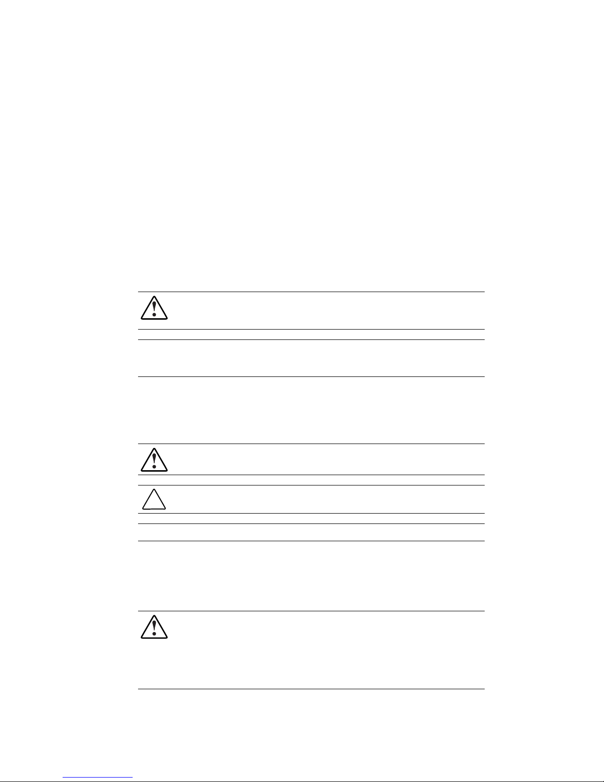
WARNING: To reduce the risk of personal injury from electrical shock and hazardous energy
levels, only authorized service technicians should attempt to repair this equipment. Improper
repairs could create conditions that are hazardous.
WARNING: Text set off in this manner indicates that failure to follow directions in the warning
could result in bodily harm or loss of life.
CAUTION: Text set off in this manner indicates that failure to follow directions could result in
damage to equipment or loss of information.
IMPORTANT: Text set off in this manner presents clarifying information or specific instructions.
NOTE: Text set off in this manner presents commentary, sidelights, or interesting points of information.
Compaq Technician Notes
WARNING: Only authorized technicians trained by Compaq should attempt to repair this
equipment. All troubleshooting and repair procedures are detailed to allow only
subassembly/module level repair. Because of the complexity of the individual boards and
subassemblies, no one should attempt to make repairs at the component level or to make
modifications to any printed wiring board. Improper repairs can create a safety hazard. Any
indications of component replacement or printed wiring board modifications may void any
warranty.
Page 7
vii Compaq StorageWorks Fibre Channel Troubleshooting Guide
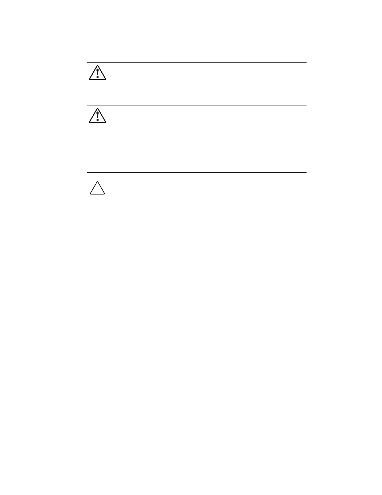
WARNING: To reduce the risk of personal injury from electrical shock and hazardous energy
levels, do not exceed the level of repair specified in these procedures. Because of the
complexity of the individual boards and subassemblies, do not attempt to make repairs at the
component level or to make modifications to any printed wiring board. Improper repairs could
create conditions that are hazardous.
WARNING: To reduce the risk of personal injury from electric shock or damage to the
equipment:
■ If the system has multiple power supplies, disconnect power from the system by
unplugging all power cords from the power supplies.
■ Do not disable the power cord grounding plug. The grounding plug is an important safety
feature.
■ Plug the power cord into a grounded (earthed) electrical outlet that is easily accessible at
all times.
CAUTION: To properly ventilate your system, you must provide at least 12 inches (30.5 cm) of
clearance at the front and back of the computer.
Where to Go for Additional Help
In addition to this guide, the following information sources are available:
■ User Documentation
■ Compaq Service Quick Reference Guide
■ Service Training Guides
■ Compaq Service Advisories and Bulletins
■ Compaq QuickFind
■ Compaq Insight Manager
■ Compaq Download Facility: Call 1-281-518-1418
Page 8

Telephone Numbers
For the name of your nearest Compaq Authorized Reseller:
■ In the United States, call 1-800-345-1518
■ In Canada, call 1-800-263-5868
For Compaq technical support:
■ In the United States and Canada, call 1-800-386-2172
■ For Compaq technical support phone numbers outside the United States and Canada, visit
the Compaq website:
About This Guide viii
http://www.compaq.com.
Page 9

Chapter 1
Introduction
The Compaq StorageWorks Fibre Channel Troubleshooting Guide provides a description of
Compaq StorageWorks RAID Array 4000 and 4100 components for primary and Enterprise
Backup Solution components for secondary storage systems. It also provides a description of the
Compaq Fibre Channel Fault Isolation Utility, the Fibre Channel Diagnostics Utility, and
includes detailed troubleshooting flow charts to help isolate problems on a Fibre Channel
Arbitrated Loop (FC-AL).
The Compaq Fibre Channel Fault Isolation Utility is used to verify the installation and operation
of a new or existing FC-AL. The Fibre Channel Fault Isolation Utility displays all devices that
are logged on the FC-AL properly and tests for link errors within the FC-AL.
After determining a suspected faulty component, additional troubleshooting details are available
in that component’s installation or user guide.
Page 10
1-2 Compaq StorageWorks Fibre Channel Troubleshooting Guide
Fibre Channel Arbitrated Loop Components in a
Primary Storage System
NOTE: Although RA4000(s) are illustrated throughout this guide, features also apply to RA4100(s).
A typical Fibre Channel Arbitrated Loop for a primary storage system consists of the following:
■ One to eight Fibre Channel Host Bus Adapters (PCI) per server
■ At least one Storage Hub 7 or Storage Hub 12
■ At least one Compaq RA4000 consisting of at least one RA4000 Controller and several
hot-pluggable SCSI hard drives
■ Two longwave or shortwave GigaBit Interface Converter (GBIC) modules per Fibre
Channel cable link
■ Multi-mode or single mode Fibre Channel cables. One cable is connected between the
Storage Hub 7 or Storage Hub 12 and each component on the FC-AL.
Fibre Array
Rack-Mountable
Server
Fibre Array
(Tower)
Fibre Channel
Storage Hub 7
Gigabit Interface
Converter
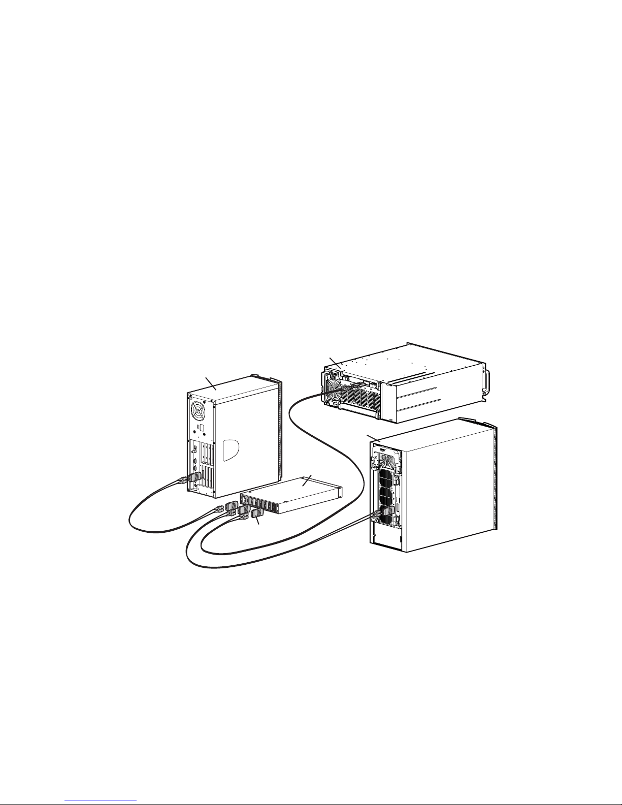
Figure 1-1. Compaq Fibre Channel Primary Storage System with RA4000(s)
Page 11
FC-AL Components in a Primary Storage System
Reference Component
Introductio n 1-3
Table 1-1
Server
RA4000 Rack-Mountable
RA4000 (Tower)
Fibre Channel Storage Hub 7
GigaBit Interface Converter
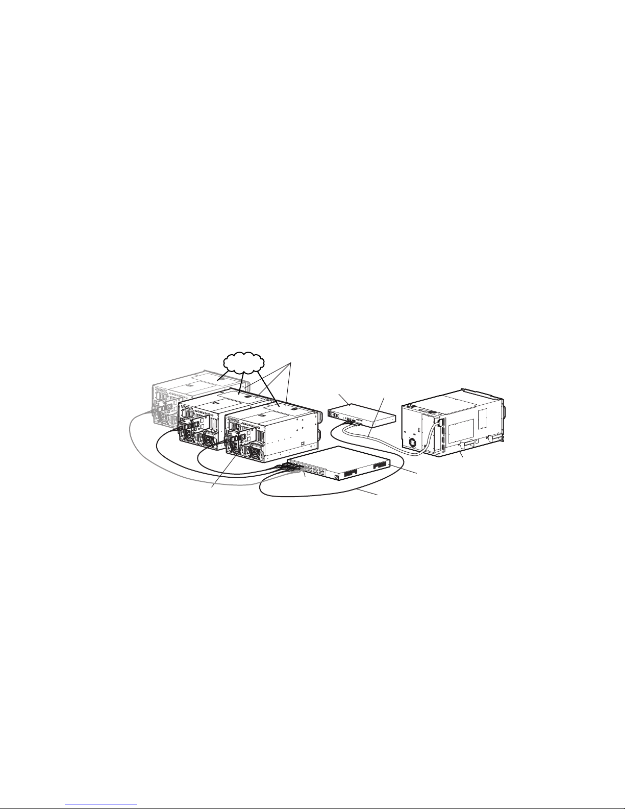
Compaq StorageWorks RAID Array 4000 System with
Redundant Components
A Compaq StorageWorks RAID Array 4000 system with redundant components consists of:
■ Two Fibre Channel Host Bus Adapters (PCI only)
■ Two storage hubs (7 or 12)
■ At least one Compaq RA4000 consisting of two RA4000 Controllers and several hot-
pluggable SCSI hard drives
■ Two longwave or shortwave GigaBit Interface Converter (GBIC) modules per Fibre
Channel cable link
■ Multi-mode or single mode Fibre Channel cables. One cable is connected between the
Storage Hub 7 or Storage Hub 12 and each component on the FC-AL.
3
1
3
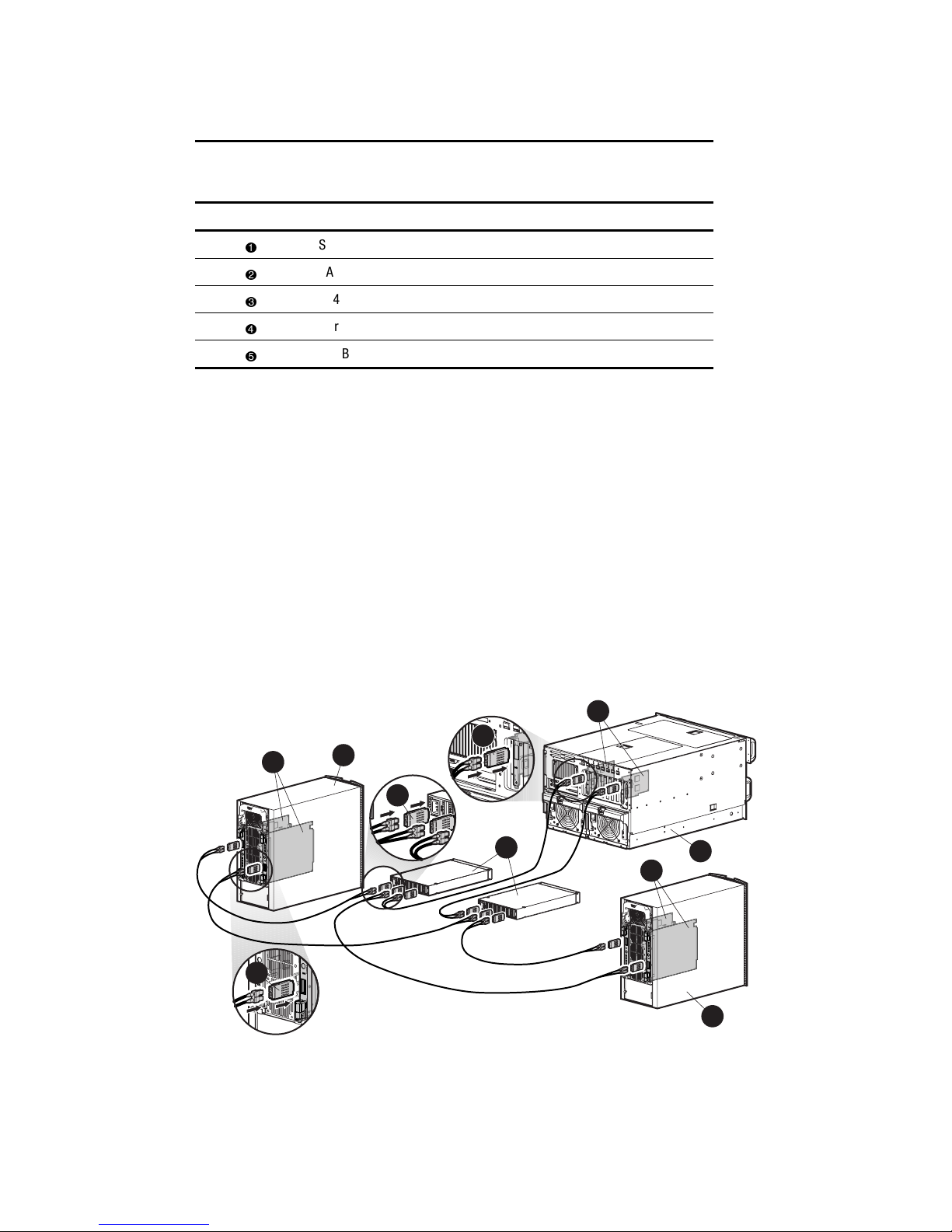
Figure 1-2. Compaq Fibre Channel Primary Storage System with two RA4000(s)
2
3
5
4
6
1
2
Page 12
1-4 Compaq StorageWorks Fibre Channel Troubleshooting Guide
Table 1-2
Fibre Channel Primary Storage System with Two RA4000s
Reference Component
RA4000 Controller
RA4000
GigaBit Interface Converters
Fibre Channel Host Bus Adapter
Fibre Channel Storage Hub 7 or 12
Server
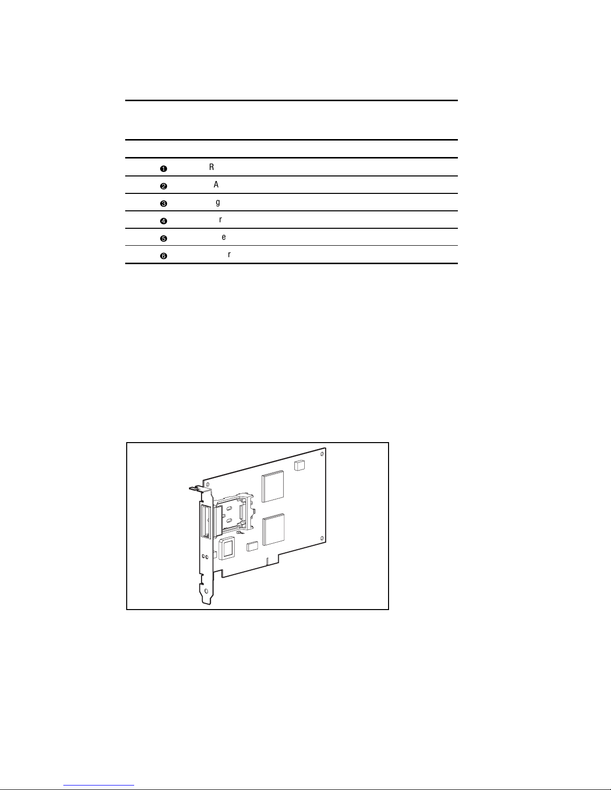
Fibre Channel Host Bus Adapter/P
The Fibre Channel Host Bus Adapter/P is installed in a server with a Peripheral Component
Interconnect (PCI) local bus. The Fibre Channel Host Bus Adapter/P provides an interface
between the PCI bus in the server and the Fibre Channel Arbitrated Loop (FC-AL).
The PCI bus is a high-performance, 32-bit bus with multiplexed address and data lines, and
parity information. It provides a high-speed (up to 132 MB/sec) path between the system board
and the Fibre Channel Host Bus Adapter/P. The Fibre Channel Host Bus Adapter/P is a PCI Bus
Master device and conforms to the current PCI Local Bus Specification.
The Fibre Channel Host Bus Adapter/P requires the installation of a GigaBit Interface Converter
(GBIC) module before the Fibre Channel cable is connected.
Figure 1-3. Fibre Channel Host Bus Adapter/P
Page 13
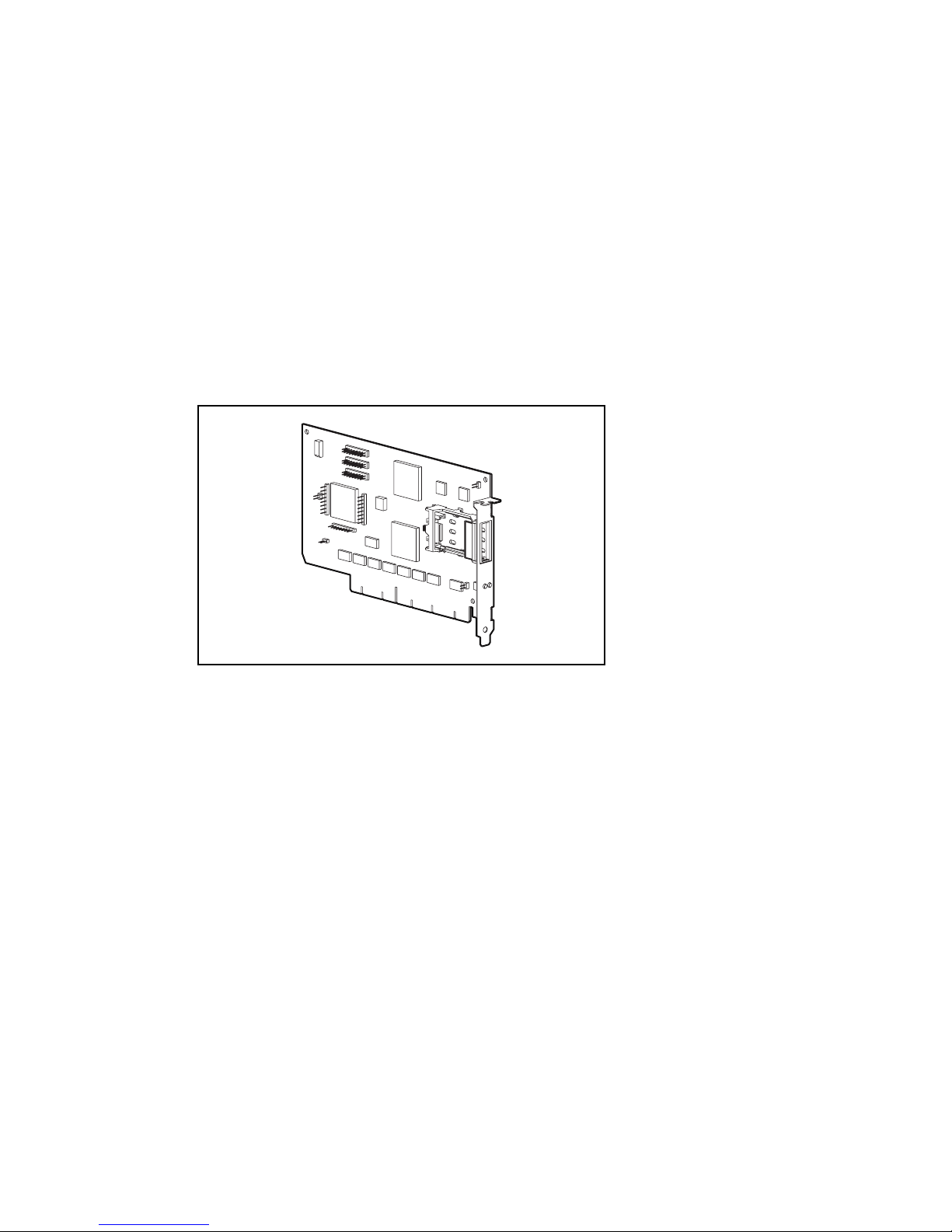
Fibre Channel Host Bus Adapter/E
The Fibre Channel Host Bus Adapter/E was designed for use in a server equipped with the
EISA expansion bus. The Fibre Channel Host Bus Adapter/E, under the control of the operating
system and dedicated device drivers, provides an interface between the EISA bus in the server
and a (FC-AL).
The EISA expansion bus delivers the capabilities required by high-performance, 32-bit
expansion boards, while maintaining compatibility with existing 8- and 16-bit ISA expansion
boards. The Fibre Channel Host Bus Adapter/E takes advantage of the EISA architecture by
performing 32-bit bus master-burst transfers.
The Fibre Channel Host Bus Adapter/E requires the installation of a GBIC module, in the
receptacle provided, before the Fibre Channel cable is connected.
Introductio n 1-5
Figure 1-4. Fibre Channel Host Bus Adapter/E
Page 14
1-6 Compaq StorageWorks Fibre Channel Troubleshooting Guide
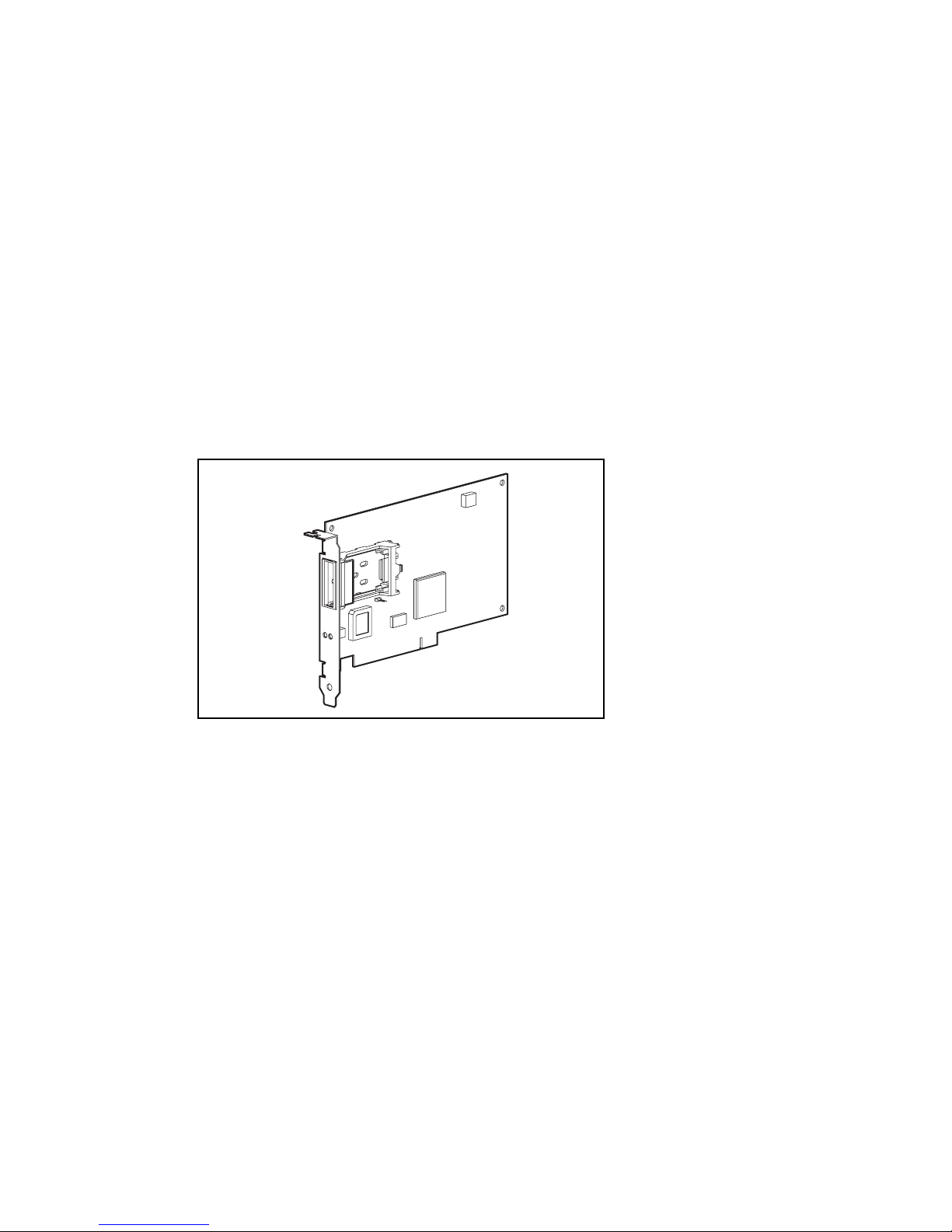
64-Bit/66-MHz Fibre Channel Host Adapter
The 64-Bit/66-MHz Fibre Channel Host Adapter is installed in a server with a PCI local bus and
provides an interface between the PCI bus in the server and Fibre Channel-connected external
storage systems.
The 64-Bit/66-MHz Fibre Channel Host Adapter interface to the server is the Peripheral
Component Interconnect (PCI) bus. The PCI interface is a high-performance, 64-Bit/66-MHz
bus with multiplexed address and data lines, and parity information. It provides a high-speed (up
to 528 MB/s) path between the system board and the Host Adapter. The 64-Bit/66-MHz Fibre
Channel Host Adapter is a PCI Bus Master device and conforms to the current PCI Local Bus
Specification.
The Host Adapter requires the installation of a GigaBit Interface Converter (GBIC) module
before the Fibre Channel cable is connected. The GBIC converts electrical signals to optical
signals, and vice versa, for transmission across the Fibre Channel media. The Fibre Channel
cable connector is plugged into the installed GBIC module.
Figure 1-5. 64-Bit/66-MHz Fibre Channel Host Adapter
Page 15
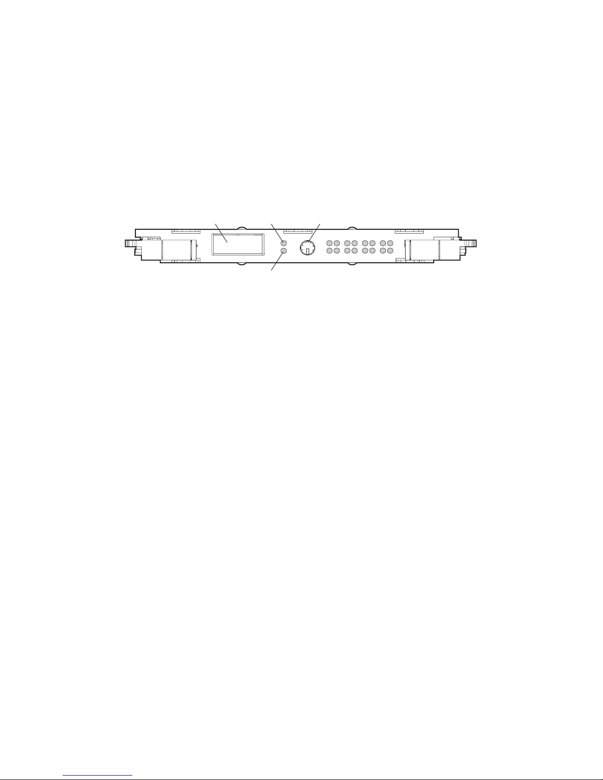
RA4000 Controller
The RA4000 Controller is a drive array controller designed to be installed in the Compaq
StorageWorks RA4000 and RA4100. The RA4000 Controller supports Fast-SCSI-2, Fast-Wide
SCSI-2, or Wide-Ultra SCSI-3 hot-pluggable hard drives. The RA4000 comes equipped with
one RA4000 Controller installed. A second RA4000 Controller may be added for a redundant
configuration. Refer to the Compaq StorageWorks RAID 4000 User Guide (P/N 340428-001) or
Compaq StorageWorks RAID 4100 User Guide (P/N146297-001) for more information about
configuration.
Introductio n 1-7
GBIC
Receptacle
Figure 1-6. RA4000 Controller
Transmit
LED
Receive
LED
Serial Debug
Por t
15 14 13 12 11 10 9 8
76 54 32 10
Features
The advanced features supported by the RA4000 Controller include:
■ Support for RAID 0, 1, 4, and 5 fault tolerance options
■ Fibre Channel support for connection to the server
■ Support for Fast-SCSI-2, Fast-Wide SCSI-2, or Wide-Ultra SCSI-3 hot-pluggable hard
drives
■ Online capacity expansion, volume extension, RAID migration, and stripe size migration
■ Removable Array Accelerator—battery-backed, configurable 16-MB or 48-MB
Read/Write Cache with ECC (Error Checking and Correcting) memory, along with a
16-MB Read Cache on the controller board
■ Performance monitoring through Compaq Insight Manager
■ Automatic performance tuning
■ Pre-failure notification on hard drives
■ Array Configuration Utility
■ Read-ahead caching
■ Tagged command queuing
■ Multiple logical drives per drive array
Page 16

1-8 Compaq StorageWorks Fibre Channel Troubleshooting Guide
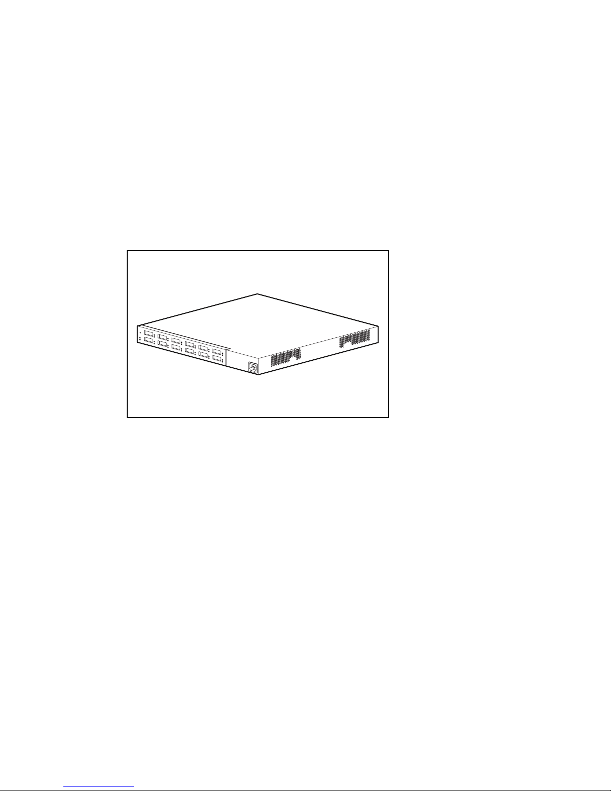
Storage Hub 7
The Compaq Fibre Channel Storage Hub 7 functions as the central point of interconnect for the
FC-AL. The Storage Hub 7 has seven I/O ports located on the rear of the unit.
Figure 1-7. Compaq Fibre Channel Storage Hub 7
Features
The Compaq Storage Hub 7 includes the following features:
■ Versatility—seven user-configurable media interface ports
■ Scalability—add or modify the loop as requirements dictate
■ Expandability—supports up to six storage devices per Fibre Channel Host Bus Adapter
■ Spatial economy—takes up only 1U of rack space
■ Compatibility—adheres to the ANSI FC-AL standard
■ Convenience—standalone or rack-mountable models
Table 1-3
Functional Specifications
Function Value
Data rate 1062.5 Mbaud
Data format 8 bit/10 bit
Number of ports 7
AC input power range 100 to 250 VAC, 50 to 60 Hz
Power consumption <25 Watts (all ports empty)
Temperature
Operating: 0 °C to 50 °C
Humidity Operating: 5% to 95%, non-condensing
Page 17
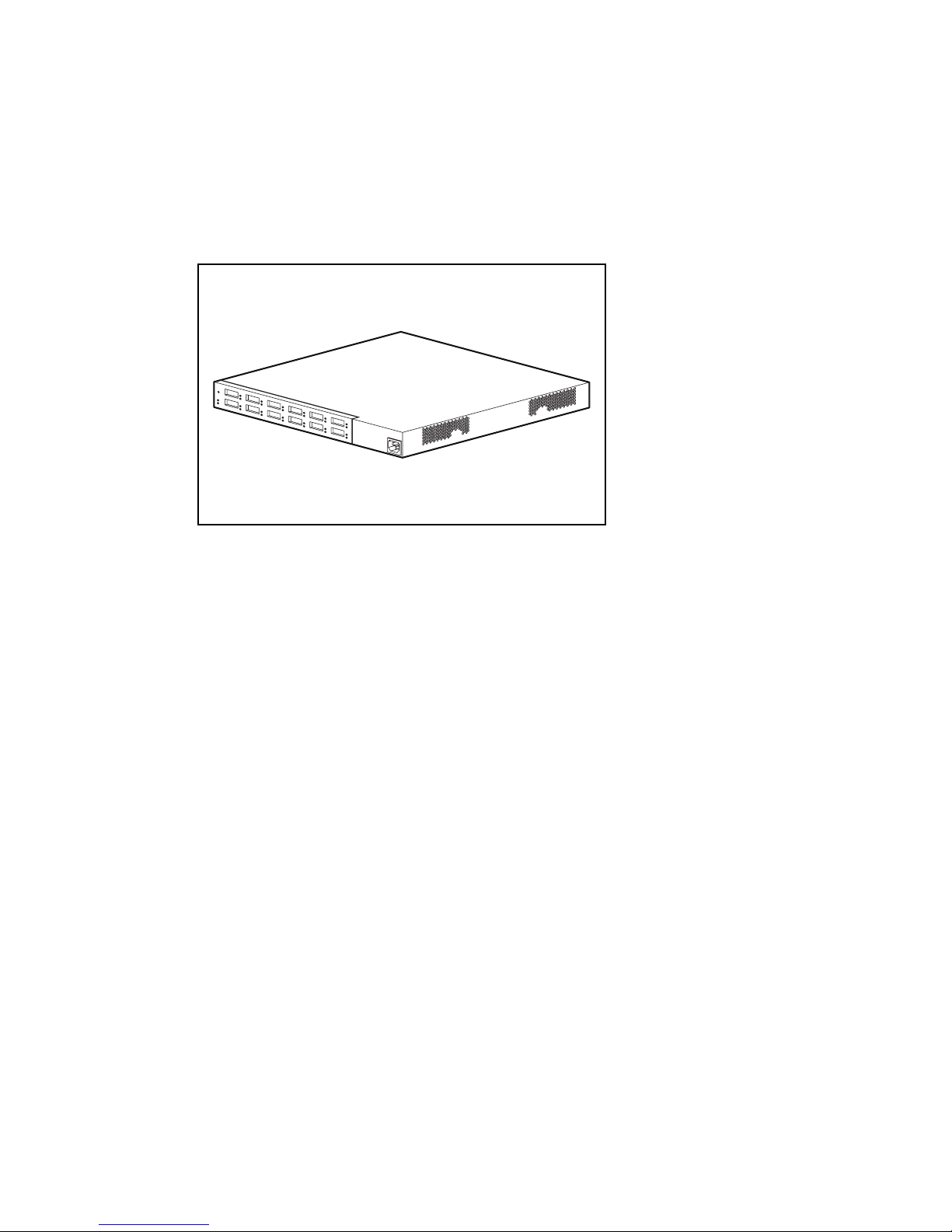
Storage Hub 12
The Storage Hub 12 continuously monitors and automatically configures devices added or
removed from the FC-AL. Adding valid FC-AL nodes is a plug-and-play operation. FC-AL
nodes that are missing or inoperative are detected, and the data is automatically routed to the
next operational port and node on the FC-AL.
The Storage Hub 12 is transparent to the data passing through it. It does not consume any
FC-AL addresses. Because of the intelligent signal detection tests, only valid Fibre Channel
devices will be connected to the FC-AL. When devices are added to the FC-AL, the Storage
Hub 12 will automatically test the new device and accept it into the FC-AL. Faulty devices will
be dropped by the Storage Hub 12 and dynamic node addressing will maintain the overall
FC-AL integrity.
Introductio n 1-9
Figure 1-8. Compaq Fibre Channel Storage Hub 12
Features
■ Expandability and Performance—supports 12 GigaBit Interface Converter modules
■ Flexibility—adheres to the ANSI FC-AL standard
■ Intelligent Port Control—provides multiple data checks without affecting performance
■ Ease of Use—provides port-bypass circuitry flexibility and simplifies central wiring
management
Page 18
1-10 Compaq StorageWorks Fibre Channel Troubleshooting Guide
GigaBit Interface Converter Module (GBIC)-Shortwave (SW)
The shortwave GBIC module converts electrical signals to optical serial signals for transmission
across the FC-AL and vice versa. The Fibre Channel cable connector is plugged into the
installed GBIC module.
A GBIC-shortwave module is useable at the following locations on the FC-AL:
■ The Fibre Channel Host Bus Adapter/E or Fibre Channel Host Bus Adapter/P
■ The RA4000 Controller
■ At each port connector used in the Storage Hub 7 or Storage Hub 12
Figure 1-9. GBIC SW module
Table 1-4
GBIC-SW Module Specifications
Feature Description
Compliance Fibre Channel FC-PH-2 physical layer option
100-M5-SN-1
Baud rate 1062.5 Mbaud
Fibre short wave
Laser 780 nm (non-OFC)
Optical connector interface Dual SC
Distance
50 µm dia. (preferred) or 62.5 µm
50 µm-2 to 500 meters
62.5 µm-2 to 300 meters
Page 19
GigaBit Interface Converter Module (GBIC)-Longwave (LW)
The longwave GBIC modules must be connected to your server with a single-mode Fibre
Channel cable. Only a Fibre Channel test cable is provided with this kit. A list of Fibre Channel
cable suppliers can be found at the following website address:
http://www.compaq.com/fibrechannel.
IMPORTANT: To ensure product integrity, Compaq recommends a 9/125 µm single mode Fibre Channel
cable that complies with Bellcore GR409. The cable assembly should be terminated with SC Duplex
Connectors at each end, which are NNT-SC, Bellcore 326, and IEC-874-19 compliant.
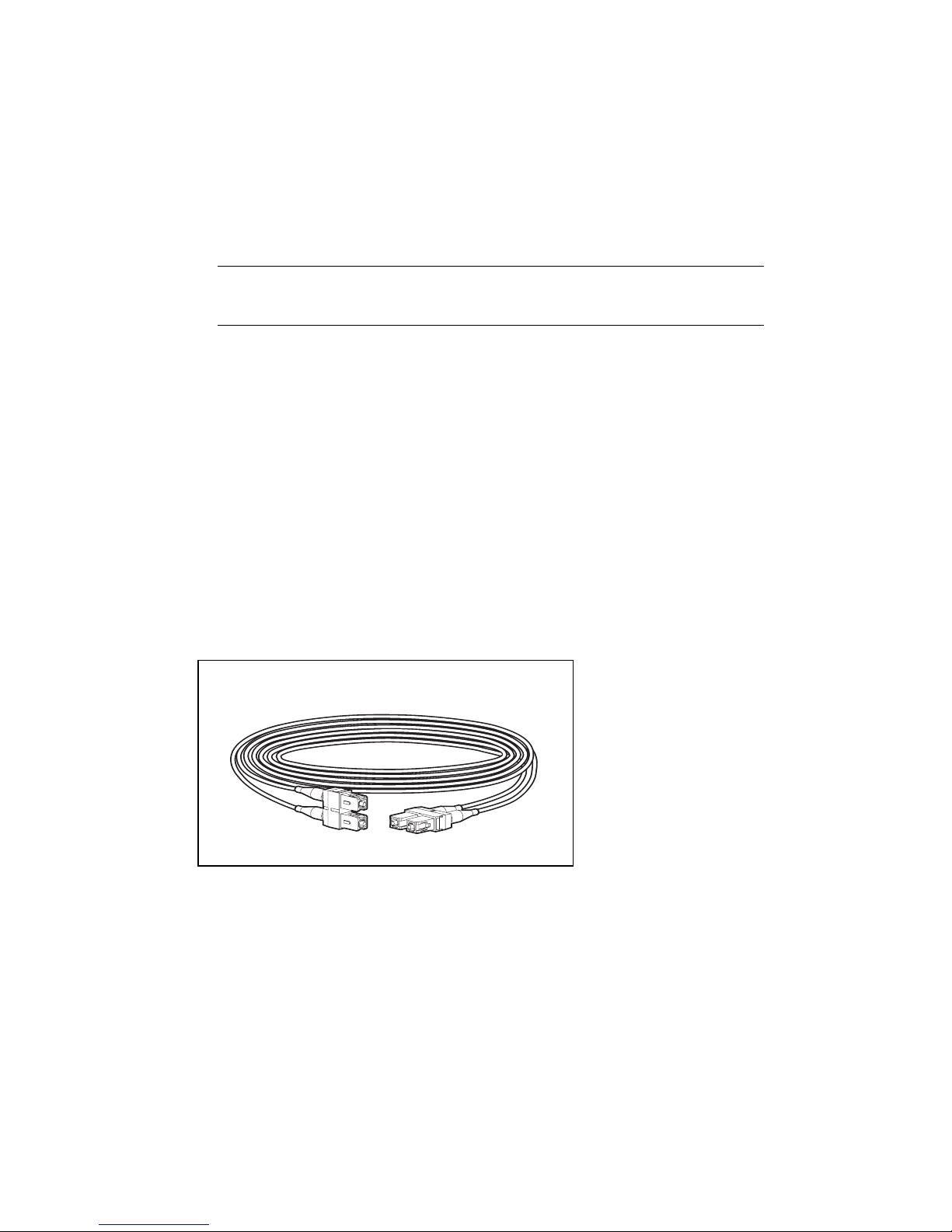
Fibre Channel Cable Option Kits
Multi-mode Fibre Channel cables are shipped with the Fibre Channel Host Bus Adapter option
kits and the RA4000 kits.
Five multi-mode Fibre Channel cable option kits are also available if different lengths are
required for your configuration. Each cable option kit contains one Fibre Channel cable with
connectors. The option kits are:
■ 2-meter multi-mode Fibre Channel Cable option kit #234457-B21
Introductio n 1-11
■ 5-meter multi-mode Fibre Channel Cable option kit #234457-B22
■ 15-meter multi-mode Fibre Channel Cable option kit #234457-B23
■ 30-meter multi-mode Fibre Channel Cable option kit #234457-B24
■ 50-meter multi-mode Fibre Channel Cable option kit #234457-B25
Figure 1-10. Fibre Channel cable with connector
Page 20

1-12 Compaq StorageWorks Fibre Channel Troubleshooting Guide
Replacing Components in a Primary Storage System
This section describes the steps required to replace FC-AL components in a StorageWorks
RAID Array 4000 or 4100 storage system. Refer to the Compaq StorageWorks Fibre Channel
Host Bus Adapter Installation Guide and Compaq StorageWorks RAID 4000 User Guide or
Compaq StorageWorks RAID 4100 User Guide for details.
Replacing the Fibre Channel Host Bus Adapter
When a Fibre Channel Host Bus Adapter fails in a non PCI Hot-Plug slot:
1. Perform a normal system shutdown of the server.
2. Power down the RA4000(s) or RA4100(s) attached to the failed Fibre Channel Host Bus
Adapter.
3. Remove the GBIC from the failed Fibre Channel Host Bus Adapter.
4. Remove the failed Fibre Channel Host Bus Adapter.
5. Install a new Fibre Channel Host Bus Adapter.
6. Install the GBIC that was removed in step 3, with the cable still attached.
7. Apply power to the RA4000(s) or RA4100(s).
8. Apply power to the server.
When a Fibre Channel Host Bus Adapter/P fails in a PCI Hot Plug slot:
1. Power down the PCI Hot Plug slot.
2. Remove the Fibre Channel cable and GBIC from the failed Fibre Channel Host Bus
Adapter.
3. Remove the failed Fibre Channel Host Bus Adapter.
4. Install the new Fibre Channel Host Bus Adapter.
5. Install the GBIC and Fibre Channel cable.
6. Power on the PCI Hot Plug slot.
Replacing the GBIC
To remove a GBIC module:
1. Remove the Fibre Channel cable from the failed GBIC. Carefully remove the GBIC
module from the receptacle on the equipment.
2. Install a GBIC into the receptacle on the equipment. The GBIC can only be installed one
way because the GBIC and the guide rails inside the equipment are keyed.
3. Install the Fibre Channel cable connector into the receptacle on the GBIC module. The
GBIC and the Fibre Channel cable connector are keyed to prevent an improper
installation.
Page 21
Replacing the RA4000 Controller without RA4000 Redundant
Controller
When an RA4000 Controller fails in an online RA4000 Array:
1. Perform a normal system shutdown of the servers.
2. Power down the RA4000.
Introductio n 1-13
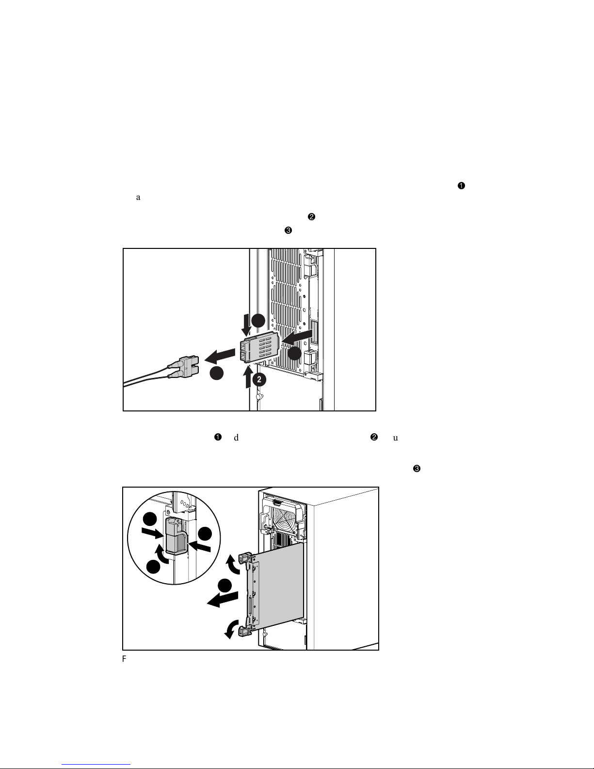
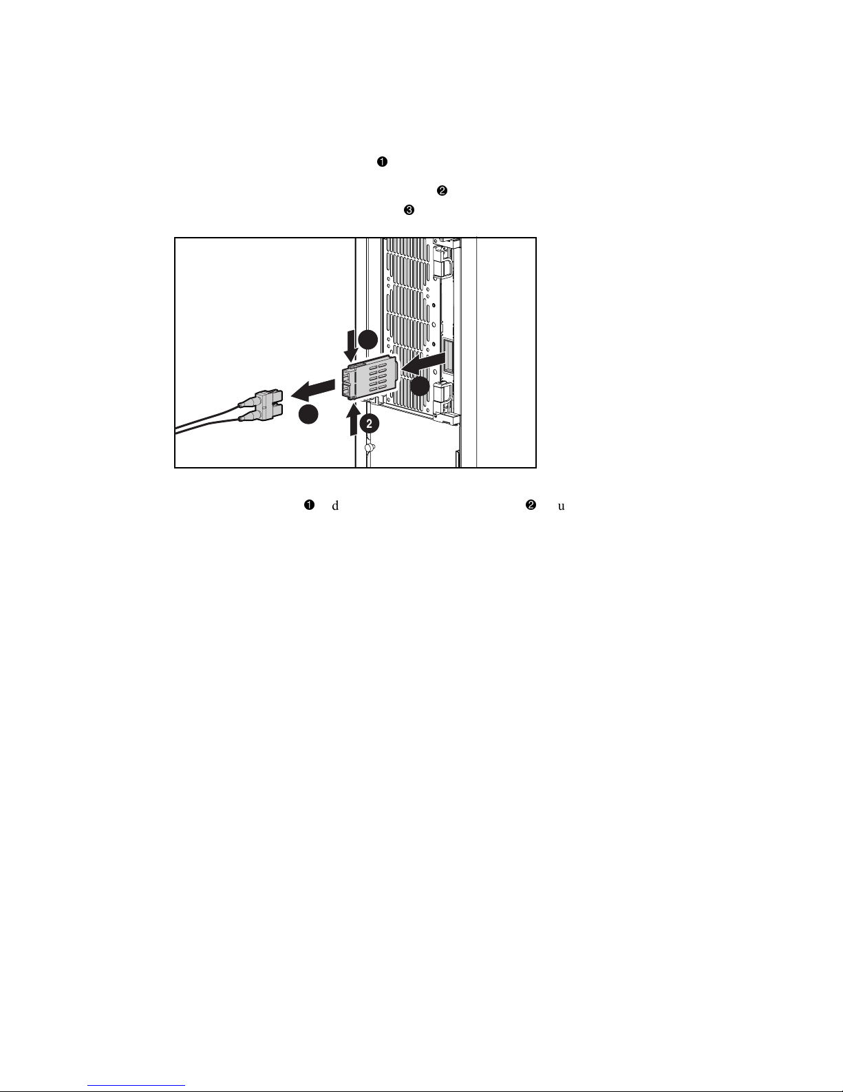
3. Unplug all power cords from the RA4000 Array. Remove the Fibre Channel cable
attached to the GBIC in the failed RA4000 Controller.
4. Squeeze the tabs on either side of the GBIC
straight out of the RA4000 Controller
2
1
Figure 1-11. Removing the Fibre Channel cable and GBIC
2
, then remove the GBIC by pulling it
.
3
5. Squeeze the latches and pivot open the two ejector levers securing the RA4000
Controller.
6. Remove the RA4000 Controller by pulling it straight out of the chassis
1
1
2
3
Figure 1-12. Removing the RA4000 Controller
.
Page 22

1-14 Compaq StorageWorks Fibre Channel Troubleshooting Guide
7. Install the replacement RA4000 Controller by inserting it into the tracks in the rear panel
opening.
8. Push the controller in as far as it will go
and close both latches against the rear panel .
The levers on each latch should catch behind the metal lip, drawing the board into position
and securing it into place.
2
1
2
Figure 1-13. Installing the RA4000 Controller
9. Replace the GBIC and connect the Fibre Channel cable.
10. Reconnect the power cords.
11. Power up the RA4000 Array.
12. Power up the servers.
The fault LED on the front panel of the RA4000 should now be green, indicating a fully
functioning system.
Page 23
Replacing the RA4000 Controller with Redundant Controller
1. Remove the Fibre Channel cable attached to the GBIC in the failed RA4000 Controller.
Introductio n 1-15
2. Squeeze the tabs on either side of the GBIC
straight out of the RA4000 Controller
2
1
Figure 1-14. Removing the Fibre Channel cable and GBIC
2
, then remove the GBIC by pulling it
.
3
3. Squeeze the latches and pivot open the two ejector levers securing the RA4000
Controller.
Page 24

1-16 Compaq StorageWorks Fibre Channel Troubleshooting Guide
4. Remove the RA4000 Controller by pulling it straight out of the chassis .
1
1
2
3
Figure 1-15. Removing the RA4000 Controller
5. Install the replacement RA4000 Controller by inserting it into the tracks in the rear panel
opening.
6. Push the controller in as far as it will go
and close both latches against the rear panel .
The levers on each latch should catch behind the metal lip, drawing the board into position
and securing it into place.
2
1
2
Figure 1-16. Installing the RA4000 Controller
7. Replace the GBIC and connect the Fibre Channel cable.
Page 25
Fibre Channel Arbitrated Loop Components in a
Secondary Storage System
A typical Fibre Channel Arbitrated Loop for a secondary storage system consists of:
■ A Fibre Channel Host Bus Adapter installed in each server
■ At least one Storage Hub 12
■ At least one Fibre Channel Tape Controller
■ One Shortwave GigaBit Interface Converter (GBIC) per Fibre Channel Host Bus Adapter
or Storage Hub 12 port. The Fibre Channel Tape Controller has a fixed GLM port and
does not require a GBIC. The Fibre Channel Tape Controller II requires the use of a
GBIC.
■ A multi-mode Fibre Channel Cable connected between the Storage hub 12 and the Fibre
Channel Host Bus Adapter in the server
■ A multi-mode Fibre Channel Cable connected between the Storage Hub 12 and each Fibre
Channel Tape Controller or Fibre Channel Tape Controller II
■ An Ethernet connection to a common LAN for servers in a multi-initiator environment
Introductio n 1-17
LAN
Fibre Channel
Host Bus Adapter
Figure 1-17. Fibre Channel Secondary Storage System
Fibre Channel Host Bus Adapter/P
This section contains information on the Fibre Channel Host Bus Adapter/P. See page 1-4 of
this guide for details.
Storage Hub 12
The Storage Hub 12 continuously monitors and automatically configures devices added or
removed from the FC-AL. Adding valid FC-AL nodes is a plug-and-play operation. FC-AL
nodes that are missing or inoperative are detected by the Storage Hub 12 and the data is
automatically routed to the next operational port and node on the FC-AL.
Generic Servers
Fibre Channel
Tape Controller
Gigabit
Interface
Converter
SCSI Cable
Tape Storage
Fibre Channel
Storage Hub 12
Fibre Channel
Cable
Page 26
1-18 Compaq StorageWorks Fibre Channel Troubleshooting Guide
The Storage Hub 12 is transparent to the data passing through it. It does not consume any
FC-AL addresses. Because of the intelligent signal detection tests, only valid Fibre Channel
devices will be connected to the FC-AL. When devices are added to the FC-AL, the Storage
Hub 12 will automatically test the new device and accept it into the FC-AL. Faulty devices will
be dropped by the Storage Hub 12 and dynamic node addressing will maintain the overall
FC-AL integrity.
Figure 1-18. Storage Hub 12
Features
■ Expandability and Performance—supports 12 GigaBit Interface Converter modules
■ Flexibility—adheres to the ANSI FC-AL standard
■ Intelligent Port Control—provides multiple data checks without affecting performance
■ Ease of Use—provides port-bypass circuitry flexibility and simplifies central wiring
management
■ Optional Management module- offers management capability through Hub Management
Utility
Page 27

Fibre Channel Tape Controller
The Compaq Fibre Channel Tape Controller provides differential SCSI bus connections and a
port for connection to the FC-AL. It provides connectivity for a single SCSI Fast/Wide or
Ultra SCSI bus running the SCSI Fibre Channel Protocol (FCP).
The form factor is 1U (1.7 inches high) and is intended for a standard Compaq Rack System
environment. All connections are on the rear panel of the unit.
Once the configuration is defined, operations of the Fibre Channel Tape Controller are
transparent to application clients.
Introductio n 1-19
Figure 1-19. Fibre Channel Tape controller
Features
■ Built in 1.0625 Gigabaud Link Module (GLM) shortwave port
■ User configuration through a standard serial interface at 9600 baud
■ Adheres to ANSI FC-AL (FCP) and PLDA (SCSI-3) and is Class 3-compliant
■ Future 802.3 10 Base T port for SNMP management agent and remote configuration
Page 28

1-20 Compaq StorageWorks Fibre Channel Troubleshooting Guide
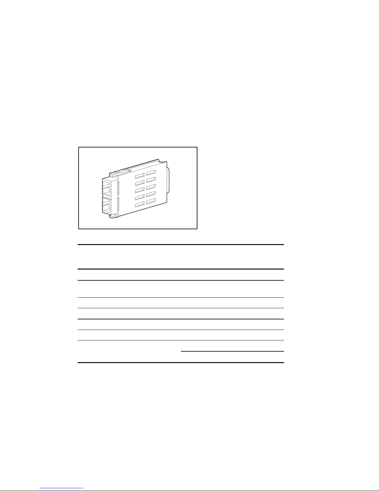
Fibre Channel Tape Controller II
The Compaq StorageWorks Fibre Channel Tape Controller II (FCTC-II) is a 1U (1.7-inch tall)
Fibre Channel-to-SCSI bridge that allows a differential SCSI tape device to communicate with
other devices over a Fibre Channel. The tape controller is designed to work as part of an
Enterprise Backup Solution.
Figure 1-20. Compaq Fibre Channel Tape Controller II
The Compaq Fibre Channel Tape Controller II connects a Fibre Channel link to a SCSI bus. The
tape controller connects to a Fibre Channel Storage Hub through a fiber cable, and also connects
to a SCSI bus device (a secondary tape storage system) using the conventional SCSI interface
and cables. After the tape controller has been installed and connected to the other components in
the Enterprise Backup Solution, its operations are transparent to the application clients.
NOTE: The Compaq StorageWorks Fibre Channel Tape Controller II is designed to work
with multiple servers, Fibre Channel Storage Hubs, and tape storage devices. For
additional information on system configurations, search the Compaq website for the white
paper on this subject at www.compaq.com.
Features
The Compaq StorageWorks Fibre Channel Tape Controller II provides a connection between a
single GigaBit per second Fibre Channel Interface and Dual SCSI Channels. Features of the
Fibre Channel Tape Controller II include:
■ Easy mounting in a rack or on a desktop with little physical configuration required.
■ Detection of any connected SCSI devices during the power-on process (or by an option on
the Power-On Menu).
Fibre Channel Features
■ One 1.0625 Gbps Fibre Channel port (removable GBIC interface)
■ Fibre Channel Arbitrated Loop (FC-AL) and Fibre Channel Switched Fabric (FCSW)
topologies
■ Private Loop Direct Attach (PLDA) profile compliance
■ Class 3 connection with SCSI-FCP protocol
■ Optical GBIC
Page 29

GigaBit Interface Converter Module-Shortwave
This section contains information on the GigaBit Interface Converter Module-Shortwave. See
page 1-10 of this guide.
Fibre Channel Cable Option Kits
This section contains information on the Fibre Channel Cable Option Kits. See page 1-11 of this
guide.
Replacing Components in a Secondary Storage
System
This section describes the steps required to replace devices connected to the Fibre Channel
Arbitrated Loop (FC-AL).
Replacing the Fibre Channel Host Bus Adapter
WARNING: To reduce the risk of personal injury or damage to the equipment, refer to the
documentation supplied with the RAID Array and observe the appropriate safety precautions
and option installation instructions before following these procedures.
Introductio n 1-21
When a Fibre Channel Host Bus Adapter fails, in a non PCI Hot Plug slot:
1. Perform a normal system shutdown of the server.
2. Power down the secondary storage components attached to the failed Fibre Channel Host
Bus Adapter.
3. Remove the GBIC from the failed Fibre Channel Host Bus Adapter.
4. Remove the failed Fibre Channel Host Bus Adapter.
5. Install a new Fibre Channel Host Bus Adapter.
6. Install the GBIC that was removed in step 3, with the cable still attached.
7. Apply power to the secondary storage components.
8. Apply power to the server.
When a Fibre Channel Host Bus Adapter/P fails in the PCI Hot Plug slot:
1. Power down the PCI Hot Plug slot.
2. Remove the Fibre Channel cable and GBIC from the failed Fibre Channel Host Bus
Adapter.
3. Remove the failed Fibre Channel Host Bus Adapter.
4. Install the new Fibre Channel Host Bus Adapter.
5. Install the GBIC and Fibre Channel cable.
6. Power on the PCI Hot Plug slot.
Page 30

1-22 Compaq StorageWorks Fibre Channel Troubleshooting Guide
Replacing a GBIC
To replace a GBIC:
1. Remove the Fibre Channel cable from the failed GBIC. Carefully remove the GBIC from
the receptacle on the equipment.
2. Install a known good GBIC into the receptacle on the equipment. The GBIC can only be
installed one way because the GBIC and the guide rails inside the Fibre Channel Host Bus
Adapter receptacle are keyed.
3. Install the Fibre Channel cable connector into the receptacle on the GBIC. The GBIC and
the Fibre Channel cable connector are keyed to prevent an improper installation.
Replacing a Storage Hub 12
When a Storage Hub 12 fails in an online active system:
1. Perform a normal system shutdown of the Fibre Channel Tape Controller, Storage Hub 12,
SCSI devices, and the server or servers affected.
2. Remove the Fibre Channel cables and associated GBICs. GBICs and cables may be
removed together with normal handling precautions.
3. Replace the failed Fibre Channel Storage Hub with a known good unit.
4. Replace the GBICs and associated Fibre Channel cables.
5. Connect the power cord and perform a power-on self-test. Normal operating mode will
show green LEDs on the rear panel for active connections. Fault LEDs and vacant GBIC
receptacle LEDs will remain off.
6. Restart the Storage System and the server or servers affected.
Replacing a Fibre Channel Tape Controller
When a Fibre Channel Tape controller fails in an online active system:
1. Perform a normal system shutdown of both the Fibre Channel Tape controller and the
server or servers.
2. Remove the Fibre Channel cable connector from the failed Fibre Channel Tape controller.
3. Remove the SCSI cable connectors from the Fibre Channel Tape controller.
4. Replace the failed Fibre Channel Tape controller. Attach the Fibre Channel cable
connector, removed earlier, to the connector on the controller.
5. Attach the SCSI cable, removed earlier, to the connector on the Fibre Channel Tape
controller.
6. Restart the Fibre Channel Tape controller and the server or servers effected.
Page 31

Chapter 2
Fibre Channel Fault Isolation Utility
The Fibre Channel Fault Isolation Utility (FFIU) verifies the integrity of a new or existing FCAL installation. When used with troubleshooting flow charts, this utility provides fault detection
and help in locating a failing device on the FC-AL.
Each device on the FC-AL has an Arbitrated Loop Physical Address (ALPA). The ALPA is
allocated dynamicallyit can change with each power-up or as new devices are added to the
loop. The fault isolation utility indicates all devices that are active on the FC-AL. The utility
dynamically updates the screens to show the current ALPA of each component. Additionally, a
Loop Error Histogram is displayed when specific servers or components are highlighted to
further analyze the health of individual components. The utility analyzes Fibre Channel
components including the Host Bus Adapter and the Fibre Channel Tape Controller. The Fibre
Channel Storage Hub 12 is logically transparent to the operations of the FC-AL, but even a
failed Storage Hub 12 can be detected when the Fault Isolation Utility is used in combination
with the Troubleshooting Flow Charts.
Installing the Utility
The latest files for the Fibre Channel Fault Isolation Utility, as well as information about
installing the utility, are located on the Compaq SmartStart and Support Software CD.
Running the Utility
To run the Fibre Channel Fault Isolation Utility:
1. Insert the SmartStart and Support Software CD in the CD-ROM drive.
2. Select Run Fibre Channel Interconnect Diagnostics.
3. Select Next. The Windows-based utility will load automatically.
Page 32

2-2 Compaq StorageWorks Fibre Channel Troubleshooting Guide
Program Displays
The utility's main display is shown below. It displays each FC-AL from the perspective of the
server. All Fibre Host Bus Adapters in the server are shown with a slot number and indicate a
PCI (/P) or EISA (/E).
NOTE: The Enterprise Backup Solution only supports PCI Host Bus Adapters to ensure adequate
performance.
Each Fibre Channel Array and Fibre Channel Tape Controller is shown as a branch of the Fibre
Host Adapter that it is connected to. The Arbitrated Loop Physical Address (ALPA) is shown
for each Fibre Channel Controller.
Figure 2-1. The Fibre Channel Fault Isolation Utility’s Main Display
Page 33

Display of a Fibre Channel Tape Controller
The Fibre Channel Fault Isolation Utility displays detailed information about any Fibre Channel
Tape Controller connected to the FC-AL. The figure below shows a Fibre Channel Tape
Controller selected, with detailed information about this tape controller displayed to the right. A
Fibre Channel Array Controller is also shown on a separate FC-AL.
Fibre Channel Fault Isolation Utility 2-3
Figure 2-2. Detailed information Displayed about a Tape Controller
The information displayed in the data field includes:
■ Vendor ID: Identifies the vendor of the target controller
■ Product ID: Identifies the product
■ Product Revision: Revision level of the product
■ World Wide Name: A unique identifier in a Fibre Channel system, different for each
Fibre Channel Component.
There is no correspondence between the order in which Fibre Channel target controllers appear
on this screen and how they are physically connected on the FC-AL. The display shows the
Fibre Channel target controllers are connected to the same FC-AL as the Fibre Channel
Controller indicates.
Page 34

2-4 Compaq StorageWorks Fibre Channel Troubleshooting Guide
Loop Error Histogram Display
The Loop Error Histogram indicates errors detected on the FC-AL when a Fibre Channel Host
Bus Adapter is highlighted. Each bar represents a 3 second period of activity. The histogram
scrolls from right to left. The figure below shows a single error period. Notice that FC-AL errors
do not update the histogram unless a Fibre Channel Host Bus Adapter is highlighted. This
occurs because the server's only view of the FC-AL is through the Fibre Channel Host Bus
Adapter, yielding no real indication of where the source of errors may be. When errors are
displayed, individual components may be disconnected from the FC-AL to determine the failing
cable, GBIC, or component.
Figure 2-3. The Loop Error Histogram, showing a single 3 second error interval
Selecting the server causes the sum of all errors on all FC-ALs to be displayed. Selecting a
different Fibre Channel Host Bus Adapter will display the errors associated with that FC-AL.
Page 35

Fibre Channel Fault Isolation Utility 2-5
Display of a FC-AL with a Missing Fibre Channel Tape Controller
The figure below shows a Fibre Channel Host Bus Adapter highlighted with a Fibre Channel
Tape Controller missing. This indicates that while the Tape Controller has become inactive on
the FC-AL since the utility was started. This could mean that it has been physically
disconnected or that errors are occurring on the FC-AL at a great enough frequency to prevent
the device from maintaining login.
If there are a large number of errors occurring in the FC-AL, the Fibre Channel Host Bus
Adapter may not be able to communicate with the Fibre Channel Tape Controllers on the
FC-AL. In this case, the Fibre Channel Controllers may appear to be offline in the program,
although in reality they are physically connected to the FC-AL. When a FC-AL shows errors,
the Fibre Channel Array and Tape Controllers may alternate between being logged-on the
FC-AL or missing.
Figure 2-4. Display of a FC-AL with two Fibre Channel Tape Controllers shown as missing
Page 36

2-6 Compaq StorageWorks Fibre Channel Troubleshooting Guide
Uninitialized Fibre Channel Arbitrated Loop Display
In the figure below, the FC-AL connected to the Fibre Channel Host Bus Adapter in Slot 1 has
not initialized. This can be derived from the Fibre Channel Host Bus Adapter having the default
ALPA of 255. If this controller was already initialized as part of an FC-AL, it would have a
valid ALPA.
Figure 2-5. Display showing uninitialized FCTC in Slot 1
Information and Updates
For more information on Fibre Channel Arbitrated Loop, see additional white papers at
www.compaq.com/support/techpubs/whitepapers.
Page 37

Compaq Fibre Channel Diagnostics for Windows CE
The Compaq Fibre Channel Diagnostics for Windows CE is a group of hardware diagnostic
tests designed to test the RA4000 Controller. It executes on the Windows CE operating system.
The test configuration uses a serial cable connected from the handheld computer to the RA4000
Controller. It takes advantage of the built-in self test on the array controller to determine what
subsystem is failing. The areas of test include: Cache, RAM, PCI Bus, SCSI Bus, LEDs,
RA4000 Controller, Power Supply, System Fans, GBIC, and Fibre cable. The diagnostics also
display information about the RA4000 Controller such as firmware revision, worldwide name,
and board serial number.
Chapter 3
Diagnostics
Compaq Fibre Channel Diagnostics for
Windows 95/98
The Compaq Fibre Channel Diagnostics is a group of hardware diagnostic tests designed to test
the RA4000 Controller and attached SCSI drives. This is a subset of the normal Compaq
Diagnostics for Windows 95/98 that executes on the Microsoft Windows 95/98 operating
system. The first test mode is using a serial cable. It takes advantage of the built-in self test on
the RA4000 controller to determine what subsystem is failing. The areas of test include: Cache,
RAM, PCI Bus, SCSI Bus, LEDs, RA4000 Controller, Power Supply, System Fans, GBIC, and
Fibre cable. The diagnostics also display information about the RA4000 Controller such as
firmware revision, worldwide name, and board serial number. The second test mode is through
the Fibre Channel. The diagnostic displays the RA4000 controllers and logical volumes found
along with the configuration and firmware revisions. The test allows multiple logical volumes to
be simultaneously exercised while trapping any error conditions.
It is important to note this subset of the Compaq Fibre Channel Diagnostics for Windows 95/98
can not co-exist with normal Compaq Diagnostics for Windows 95/98 potentially already
installed. For the safest operation when switching between the two versions, be sure to uninstall
the current version and install the desired version according to the procedures that follow. This
ensures proper updating of the registry and other directories.
Page 38

3-2 Compaq StorageWorks Fibre Channel Troubleshooting Guide
Compaq Fibre Channel Backup Diagnostics for
Windows NT
The Compaq Fibre Channel Diagnostics is a group of hardware diagnostic tests designed to the
Compaq StorageWorks Enterprise Backup Solution. This is a subset of the normal Compaq
Diagnostics for Windows NT specifically to help identify any potential problems with the Fibre
Channel Tape Controller and the DLT 15 Cartridge Library Model 3570 on the Fibre Channel
Arbitrated Loop. It can also be used to upgrade firmware for the Fibre Channel Tape Controller,
the Fiber Channel Tape Controller II, and the DLT Cartridge Library Model 3570.
It is important to note this subset of the Compaq Fibre Channel Backup Diagnostics for
Windows NT can not coexist with normal Compaq Diagnostics for Windows NT potentially
already installed. For the safest operation when switching between the two versions, be sure to
uninstall the current version and install the desired version according to the procedures below.
This ensures proper updating of the registry and other directories.
Compaq Fibre Channel Backup Diagnostics for Windows NT will identify the FCTC (Fibre
Channel Tape Controller) and any devices attached. The information returned for each device is
as follows:
■ FCTC
ID String
Firmware Revision
Worldwide Name
Attached Device Info
ID String
Serial Number
■ Devices (such as, tape, hard drive, and changer)
ID String
Firmware Revision
Serial Number
SCSI Path (adapter, target, lun)
Tape Drives (changer only)
Tape Capacity (changer only)
Tapes Present (changer only)
The tests available to each are:
■ Changer
Test Unit Ready: queries the changer to see if a good status is returned
Force Inventory: sends an Initialize Element Status command
Move Media Test: allows the user to move a tape from any slot (or drive) to any other
empty slot or drive
Firmware Upgrade: will upgrade the firmware of the changer
Page 39

■ Tape Drive
Test Unit Ready: queries the changer to see if a good status is returned
Buffer Test: writes and reads from the tape drive's onboard cache
Firmware Upgrade: will upgrade the firmware of the tape drive
■ FCTC
Firmware Upgrade: will upgrade the firmware of the FCTC and the FCTC II
Installing Compaq Fibre Channel Diagnostics for
Windows CE
Compaq Fibre Channel Diagnostics for Windows CE is available on the SmartStart and Support
Software CD. It is bundled with the Compaq Diagnostics for Windows 95/98. Create the
installation diskettes by following the SmartStart instructions.
To install the utility:
1. Remove all previous versions of Compaq Diagnostics for Windows 95/98.
a. Select Start, Settings, Control Panel.
b. Select Add/Remove Programs.
c. Select Compaq Diagnostics for Windows 95/98 and "Add/Remove."
2. Install this version of Diagnostics for Windows 95/98.
Diagnostics 3-3
a. Insert diskette #1 into drive A:
b. Run A:\SETUP.EXE
c. Select Next.
d. Select Finish.
3. Copy the FCDIAGCE.EXE file located in the CPQDIAGS directory.
Page 40

3-4 Compaq StorageWorks Fibre Channel Troubleshooting Guide
Installing Compaq Fibre Channel Diagnostics for
Windows 95 or 98
Compaq Fibre Channel Diagnostics for Windows 95/98 is available on the SmartStart and
Support Software CD. Create the installation diskettes by following the SmartStart instructions.
To install the utility:
1. Remove all previous versions of Compaq Diagnostics for Windows 95/98.
a. Select Start, Settings, Control Panel.
b. Select Add/Remove Programs.
c. Select Compaq Diagnostics for Windows 95 or 98 and "Add/Remove."
2. Install this version of Diagnostics for Windows 95 or 98.
a. Insert diskette #1 into drive A:
b. Run A:\SETUP.EXE
c. Select Next.
d. Select Finish.
3. Restart the computer.
Installing Compaq Fibre Channel Backup Diagnostics
for Windows NT
Compaq Fibre Channel Backup Diagnostics for Windows NT is available on the SmartStart and
Support Software CD. Create the installation diskettes by following the SmartStart instructions.
To install the utility:
1. Remove all previous versions of Compaq Diagnostics for Windows NT.
a. Select Start, Settings, Control Panel.
b. Select Add/Remove Programs.
c. Select Compaq Diagnostics for Windows NT and "Add/Remove."
2. Install this version of Diagnostics for Windows NT.
a. Insert diskette #1 into drive A:
b. Run A:\SETUP.EXE.
c. Select Next.
d. Select Finish.
3. Restart the computer.
Page 41

Chapter 4
StorageWorks RAID Array 4000 and 4100
Troubleshooting Flow Charts
This chapter contains troubleshooting flow charts that will help diagnose problems on a FC-AL
in an RA4000 and RA4100 Storage System. The flow charts are listed by problem symptoms or
troubleshooting procedures, as follows:
■ Overview of the Troubleshooting Flow Charts (page 4-2)
■ Verify System Operation (4-4)
■ Determine a Bad Link (4-6)
■ Some Fibre Array Controllers are Detected (page 4-7)
■ Visual and Physical Inspection of the FC-AL (page 4-10)
■ Checking the Link between the Storage Hub and the Fibre Channel Array Controller (page
4-12)
■ Checking the Link between the Storage Hub and the Fibre Channel Host Bus Adapter
(page 4-15)
■ Fibre Channel Loopback Test (4-17)
Page 42

4-2 Compaq StorgeWorks Fibre Channel Troubleshooting Guide
Overview of the Troubleshooting Flow Charts
The following overview of the Fibre Channel Troubleshooting Flow Charts provides a logical
approach to troubleshooting problems on the FC-AL. The Fibre Channel Fault Isolation Utility
and the appropriate flow chart can be used to help identify problem areas on the FC-AL and to
help verify that the FC-AL is functioning normally after repairs are made.
Begin
Start with the Verify
System Operation
flow chart
Was a problem found?
Ye s
FC-AL related problems
A
No
Done
Page 43

StorageWorks RAID Array 4000 and 4100 Troubleshooting Flow Charts 4-3
A
Use the Determining A Bad Link
flow chart
When using the Fibre Channel Fault
Isolation Utility, were all Fibre Channel
Array Controllers missing?
No
When using the Fibre Channel Fault
Isolation Utility, were some Fibre Channel
Array Controllers missing?
No
Ye s
Ye s
Use the Checking the Link between the
Storage Hub 7 and the Fibre Channel
Host Bus Adapter flow chart
Use the Some Fibre Channel Array
Controllers Are Detected flow chart
When using the Fibre Channel Fault
Isolation Utility, were errors on the
FC-AL indicated?
No
Done
Ye s
Use the Checking the Link between the
Storage Hub 7 and the Fibre Channel
Array Controller flow chart
Page 44

4-4 Compaq StorgeWorks Fibre Channel Troubleshooting Guide
Verify System Operation
Begin
Verify that power has been
applied to all devices on the
FC-AL
Start the Fibre Channel Fault
Isolation Utility at the server.
Ensure that each Host
Bus Adapter is fully seated.
Run System Configuration.
No
Check again with the Fault
Isolation Utility.
Do all
Fibre Channel
Host Adapters show up
on the screen?
Ye s
Do the
Fibre Channel
Host Adapters have "non-
255" valued ALPAs?
Ye s
All Fibre
Channel Devices
visible?
Ye s
B
No
No
Go to Checking the Link
between the Storage Hub 7
and the Fibre Channel Host
Adapter flow chart.
No
Still no Host
Adapters?
Ye s
Replace the Fibre Channel
Host Adapter
Go to Determining Bad Link
flow chart
Page 45

StorageWorks RAID Array 4000 and 4100 Troubleshooting Flow Charts 4-5
B
Highlight a server in the
Fault Isolation Utility
Any errors in Error
Histogram?
No
Note: Loop errors may occur briefly as
a result of starting the Fault Isolation
Utility or adding or removing Fibre
Channel Array Controllers. This is
normal.
Ye s
Go to Determining Bad Link
flow chart
Done
Page 46

4-6 Compaq StorgeWorks Fibre Channel Troubleshooting Guide
Determine a Bad Link
Begin
Are Fibre Channel Array
Controllers missing?
Are all Fibre
Channel Array Controllers
missing on a particular FC-AL?
No
Determine which Fibre Channel Array
Controllers are missing by
highlighting the server. All of
the Fibre Channel Array Controllers
attached to the Host Adapter
in the server will blink their
drive tray LEDs.
To troubleshoot the missing
Fibre Channel Array Controllers, go to
Checking the Link between the
Storage Hub 7 and Fibre Channel
Array Contoller flow chart.
Ye s
No
Were FC-AL errors
detected?
Ye s
Determine which loop has the
errors by highlighting one Host
Bus Adapter at a time and looking
at the Error Histogram.
Once the FC-AL is determined
find the failing device by
unplugging one device at a time
from the Fibre Storage Hub 7.
Watch for errors to clear from
the histogram.
Depending on the failing
device found, refer to the
Checking the Link between
the Storage Hub 7 and the
Fibre Array Controller flow
chart or Checking the Link
between the Storage Hub 7
and the Host Bus Adapter
flow chart.
Go to Checking the Link
beween the Storage Hub 7 and
the Host Bus Adapter flow chart.
No
Done
Page 47

StorageWorks RAID Array 4000 and 4100 Troubleshooting Flow Charts 4-7
Some Fibre Channel Array Controllers Are Detected
Begin
Run the Fault Isolation utility.
Determine which ALPAs are
not shown by the utility.
Is the Active LED
blinking on the Fibre Channel
Array Controller not returning an ALPA?
See Appendix A for the location
of the LED.
Ye s
C
No
Check
seating of the Fibre
Channel Array
Controller. Check to
make sure the power
supply is secure and
the power source is
active.
Page 48

4-8 Compaq StorgeWorks Fibre Channel Troubleshooting Guide
C
Is the recieve LED on?
Ye s
Is the transmit LED on?
Ye s
C1
No
No No
Run the utility if the device
is the Fibre Host Adapter.
If the device
is the Fibre Channel
Array Controller, is the Heartbeat
LED blinking?
See Appendix A.
Remove the server cable
connector from the GBIC at
the Storage Hub 7.
Is the laser light coming from
the cable connector?
Ye s
Replace the GBIC.
No
To check if light is
coming from the
cable connector, plug
the cable into a good
GBIC at the Fibre
Storage Hub 7 and
make sure the
Bypass LED goes off.
Never look into the
connector to see if
light is present.
Check the GBIC and
the Storage Hub 7.
Ye s
First replace the GBIC. If no change,
replace the Fibre Channel
Array Controller.
Replace the
Fibre Channel
Array Controller.
Page 49

C1
StorageWorks RAID Array 4000 and 4100 Troubleshooting Flow Charts 4-9
Are the active LEDs lit on the
Storage Hub 7? See Appendix A.
Ye s
Are any Bypass LEDs lit on
the Storage Hub 7 that have GBICs
and cables installed?
See Appendix A.
Ye s
Is the GBIC seated properly in
No
Replace the GBIC. if
the problem persists
replace the storage
No
Did the utility program
respond with an ALPA?
the receptacle?
Ye s
Hub 7.
Ye s
No
No
Reset the GBIC.
A device on the loop is causing the
entire loop to become unstable.
Unplug all Fibre Channel Array
Controllers from the loop except one.
Run the Utility program again. If the
Fibre Channel Array Controller appears,
plug in another Fibre Channel Array
Controller and run the utility
program again. If no Fibre
Channel Array Controllers appear,
the Fibre Channel Host Bus
Adapter in the server may be at fault.
Verify that power is applied to all
devices on the loop.
Return
Is the Active LED
blinking on all Fibre
Channel Array Controllers?
See Appendix A.
Ye s
Reset the Fibre Channel
Array Controller and run
the utility program again.
No
Possible Fibre Array problem.
Check seating of the Fibre
Channel Array Controller. Ckeck
to make sure the power supply is
secure and the power source is
active.
Page 50

4-10 Compaq StorgeWorks Fibre Channel Troubleshooting Guide
Visual and Physical Inspection of the FC_AL
Begin
Check the seating of all GBICs
and cable connectors on the
FC-AL.
Has the problem with the FC-
AL been corrected?
No
Remove each GBIC and check
visually for any defects.
Replace GBICs and make sure
each GBIC is snapped fully into
the connector. The GBIC is
keyed to fit only one way.
D
Ye s
Done
Page 51

StorageWorks RAID Array 4000 and 4100 Troubleshooting Flow Charts 4-11
D
Check that cable connector is inserted
into GBIC correctly. The cable
connector ferrules must be inserted
fully into the connector and not
recessed.
Check with the Fault Isolation
Utility to see if the problem was
corrected.
Was the problem corrected?
Ye s
Done
No
Return
Page 52

4-12 Compaq StorgeWorks Fibre Channel Troubleshooting Guide
Checking the Link Between the Storage Hub and the
Fibre Channel Array Controller
Begin
Perform a visual and physical inspection
of the FC-AL. Use the Visual and Physical
inspection of the FC-AL flow chart.
Insert the loopback plug into the GBIC at
the Fibre Channel Array Controller and run
loop back test. Go to the Fibre Channel
Loopback Test flow chart.
Possible Fibre Channel Array
problem. Check seating of the
Did loopback test fail with an
internal error message?
Ye s
Fibre Channel Array Controller.
Check to make sure the power
supply is secure and the power
source is active.
No
Did loopback test fail with an
external error message?
No
Remove the GBIC from the Storage
Hub 7 or Hub 12 and connect it to
the Fibre Channel Array Controller.
E
Ye s
Replace the GBIC.
Return
Page 53

E
Run the loopback test on this GBIC.
Go to the Fibre Channel Loopback
Test flow chart.
Did the loopback test fail
with an internal error
message?
No
StorageWorks RAID Array 4000 and 4100 Troubleshooting Flow Charts 4-13
Possible Fibre Channel Array failure. Check
Ye s
seating of the Fibre Channel Array Controller.
Check to make sure the power supply is
secure and the power source is active
Did the loopback test fail
with an external error
message?
No
Insert cable into the GBIC on the
Fibre Array Controller.
E1
Ye s
Possible Fibre Channel Array failure. Check
seating of the Fibre Channel Array Controller.
Check to make sure the power supply is
secure and the power source is active
Page 54

4-14 Compaq StorgeWorks Fibre Channel Troubleshooting Guide
E1
Attach loopback plug to the cable.
Run the loopback test with this
cable configuration. Go to the Fibre
Channel Loopback Test flow chart.
Did the loopback test fail
with an external error
message?
No
Done
Ye s
Replace the Fibre Channel cable.
Return
Page 55

StorageWorks RAID Array 4000 and 4100 Troubleshooting Flow Charts 4-15
Checking the Link Between the Storage Hub and the
Fibre Channel Host Bus Adapter
Begin
Perform a visual and physical inspection
of the FC-AL. Use the Flow Chart on
To test the GBICs and the Fibre Channel cable, remove
the GBICs and the cable from between the Fibre Channel
Host Bus Adapter and the Storage Hub 7 or Hub 12.
Test these components at the Fibre Channel Array
Controller using the loopback diagnostic and the flow chart
procedure - Checking the Link from the Storage Hub 7
or Hub 12 to the Fibre Channel Array Controller.
Use the flow chart on page 4-12
page 4-10
Another method to troubleshoot the GBICs and cable
between the Storage Hub 7 or Hub 12 and Fibre Channel
Host Bus Adapter is to replace them with new
components. Once complete, verify system
performance with the Fault Isolation Utility.
Is the FC-AL functioning
normally?
No
Connect a GBIC and cable to the Fibre
Channel Host Bus Adapter.
F
Ye s
End
Page 56

4-16 Compaq StorgeWorks Fibre Channel Troubleshooting Guide
F
Remove the GBIC from the other
end of the cable.
Place loopback plug on the end of the
cable.
Run the Fault Isolation Utility
Observe the program display for
errors.
Were there errors?
No
If the problem persists, try new
components or seek Compaq
Service
Ye s
Possible Fibre Channel Host
Bus Adapter failure.
Done
Page 57

Fibre Channel Loopback Test
Begin
The Fibre Channel Loopback test is a method to verify
proper function of cables, GBICs and nodes of your
Fibre Array system on an isolated link. The test
consists of running a diagnostic utility remotely
through a serial port connection between the Fibre
Array and a PC such as a laptop. To isolate the link, a
loopback plug is used to close the circuit. This plug is
part of the Fibre Channel Troubleshooting option kit
(P/N 234468-B21)
The Fibre Array User Diagnostics Utility (located on
the SmartStart and Suppor t Software CD) contains a
Fibre Channel loopback test function. Load the utility
on the remote computer.
StorageWorks RAID Array 4000 and 4100 Troubleshooting Flow Charts 4-17
Fibre Channel loopback plug
Use the serial cable found in the Fibre Channel
Troubleshooting option kit to connect the remote
computer to the Fibre Array.
Remove the Fibre Channel cable from the GBIC
at the Fibre Array. Insert the loopback plug into
the GBIC. Run the diagnostic utility on the laptop
or other computer.
Remove the GBIC from the Fibre Array. Insert the
GBIC from the Fibre Hub 7 into the Fibre Array.
Insert the loopback plug into the GBIC. Run the
diagnostics utility on the laptop or other computer.
G
Did the test pass?
yes
no
G1
Page 58

4-18 Compaq StorgeWorks Fibre Channel Troubleshooting Guide
G
Did the test pass?
Ye s
Insert the Fibre Channel cable into the GBIC at the
Fibre Array. Insert the Loopback plug into the
connector of the Fibre Channel cable. Run the
diagnostics utility on the laptop or other computer.
Did the test pass?
Ye s
No
G1
No
G1
Done
Page 59

G1
StorageWorks RAID Array 4000 and 4100 Troubleshooting Flow Charts 4-19
GBIC not plugged-in error?
No
Internal failure indicated?
No
External failure indicated?
Ye s
Reseat the GBIC. Return to page 4-17 to
begin the Fibre Channel Loopback Test
flowchart again.
Ye s
Replace the Fibre Channel Array
Controller.
Done
Ye s
No
Return
Replace the GBIC or Fibre Channel Cable,
depending on which was being tested.
Done
Page 60

Chapter 5
Secondary Storage System
Troubleshooting Flow Charts
This chapter contains troubleshooting flow charts that can be used to diagnose problems on a
FC-AL in a Secondary Storage System. The flow charts are listed by problem symptoms or
troubleshooting procedures, as follows:
■ Overview of the Troubleshooting Flow Charts (page 5-2)
■ Verifying FC-AL Operation (5-4)
■ Determining a Bad Link (5-6)
■ Some Fibre Channel Tape Controllers are Detected (page 5-7)
■ Visual and Physical Inspection of the FC-AL (page 5-9)
■ Checking the Link between the Storage Hub 12 and the Fibre Channel Host Bus Adapter
(page 5-11)
■ Checking the Link between the Storage Hub 12 and the Fibre Channel Tape Controller
(page 5-13)
Page 61

5-2 Compaq StorageWorks Fibre Channel Troubleshooting Guide
Overview of the Troubleshooting Flow Charts
The following overview of the Fibre Channel Troubleshooting Flow Charts provides a logical
approach to troubleshooting problems on the FC-AL. The Fibre Channel Fault Isolation Utility
and the appropriate flow chart can be used to help identify problem areas on the FC-AL and to
help verify that the FC-AL is functioning normally after repairs are made.
Begin
Start with the Verify
FC-AL Operation
flow chart
A problem with the
FC-AL indicated?
Ye s
Use the Determining a Bad Link
flow chart.
Problem with the
FC-AL indicated?
Ye s
No
No
Done
Done
A
Page 62

Secondary Storage System Troubleshooting Flow Charts 5-3
A
Run the Fibre Channel Fault Isolation
Utility.
Were all Fibre Channel Tape
Controllers missing?
No
Were some Fibre Channel Tape
Controllers missing?
No
Ye s
Ye s
Use the Checking the Link between the
Storage Hub 12 and the Fibre Host
Bus Adapter flow chart.
Use the Some Fibre Channel Tape
Controllers Are Detected flow chart.
When using the Fibre Channel Fault
Isolation Utility, were errors on the
FC-AL indicated?
No
Done
Ye s
Use the Checking the Link between the
Storage Hub 12 and the Fibre Channel
Tape Controller flow chart.
Page 63

5-4 Compaq StorageWorks Fibre Channel Troubleshooting Guide
Verifying FC_AL Operation
Begin
Verify that power has been
applied to all devices on the
FC-AL.
Start the Fibre Channel Fault
Isolation Utility at the server.
Do the
Fibre Channel Host
Adapters show up on
the screen?
Ye s
Do the
Fibre Channel Host
Bus Adapters show up on
the screen?
No
No
Ensure that each Host
Bus Adapter is fully seated.
Run System Configuration
Utility.
No
Check again with the Fault
Isolation Utility.
Still no Host
Bus Adapter?
Ye s
Replace the Fibre Channel
Host Bus Adapter.
Ye s
Are all Fibre Controllers
visible on the FC-AL?
Ye s
B
Go to Checking the Link between
the Storage Hub 12 and the Fibre
Channel Host Bus Adapter flow
chart.
No
Go to Determine Bad Link
flow chart.
Page 64

B
Highlight a server in the
Fault Isolation Utility.
Secondary Storage System Troubleshooting Flow Charts 5-5
Note: Loop errors may occur briefly
as a result of starting the Fault Isolation
Utility or adding or removing Fibre
Channel Tape Controllers. This is
normal.
Any errors in Error
Histogram?
No
Done
Ye s
Go to Determining a Bad
Link flow chart.
Page 65

5-6 Compaq StorageWorks Fibre Channel Troubleshooting Guide
Determining a Bad Link
Begin
Are Fibre Channel Tape
Controllers Missing?
Ye s
Are all Fibre Channel Tape
Controllers missing on a
particular FC-AL?
No
Determine which Tape
Controller are missing by
highlighting the server. The
Fibre Channel LED on each
Tape Controller will blink on
all working Tape Controller.
Ye s
No
Were FC-AL errors
detected?
Ye s
Determine which loop has the
errors by highlighting one Host
Controller at a time and looking
at the Error Histogram.
Once the FC-AL is determined
find the failing device by
unplugging one device at a time
from the Fibre Storage Hub 12.
Watch for errors to clear from
the histogram.
Depending on the failing
device found, refer to the
Checking the Link between
The Storage Hub 12 and the
Tape Bus Adapter flow chart or
Checking the Link between
the Storage Hub 12 and the
Host Bus Adapter flow chart.
No
Done
To troubleshoot the missing
Tape Controller, go to
Checking the Link between the
Fibre Channel Storage Hub 12
and Fibre Channel Tape
Controller flow chart.
Go to Checking the Link
between the Storage Hub 12
and the Host Bus Adapter flow
chart.
Page 66

Secondary Storage System Troubleshooting Flow Charts 5-7
Some Fibre Channel Tape Controllers are Detected
Begin
Run the Fault Isolation utility.
Determine which ALPAs are
not shown by the utility.
Is the missing
Tape Controller connected
to a FC-AL shared with other
Tape Controllers?
Ye s
B1
No
Go to the Checking the Link
between the Fibre Storage
Hub 12 and the Fibre
Channel Host Bus Adapter flow
chart.
Page 67

5-8 Compaq StorageWorks Fibre Channel Troubleshooting Guide
B1
Are any Bypass LEDs
(Amber) lit on the Storage
Hub 12? Refer to Appendix A for the
location of the LED.
Ye s
No
Is the Fibre Channel LED
flickering on the Fibre Channel
Tape Controller? Refer to
Appendix A for the location
of the LED.
Possible Fibre Channel Storage Hub 12
failure. Run Fibre Channel Storage Hub 12
diagnostics. Refer to the Fibre Channel
Storage Hub 12 Installation Guide for
details.
Possible Fibre Channel Tape Controller
problem. Run Tape Controller diagnostics.
Refer to the Fibre Channel Tape Controller
User Guide for details.
No
Ye s
If the problem persists, try new
components or seek Compaq Service.
Page 68

Secondary Storage System Troubleshooting Flow Charts 5-9
Visual and Physical Inspection of the FC_AL
Begin
Check the seating of all GBICs
and cable connectors on the
FC-AL.
Is the FC-AL functioning
normally?
No
Remove each GBIC and check
visually for any defects.
Replace GBICs and make sure
each GBIC is snapped fully into
the connector. The GBIC is
keyed to fit only one way.
C1
Ye s
Done
Page 69

5-10 Compaq StorageWorks Fibre Channel Troubleshooting Guide
C1
Verify the Cable connector is inserted
into GBIC correctly. The cable
connector ferrules must be inserted
fully into the connector and not
recessed.
Check the FC-AL with the Fibre Channel
Fault Isolation Utility to see if the problem
was corrected.
Was the problem corrected?
Ye s
Done
No
Return
Page 70

Secondary Storage System Troubleshooting Flow Charts 5-11
Checking the Link Between the Storage Hub 12 and
the Fibre Channel Host Bus Adapter
Begin
Perform a visual and physical inspection of the
FC-AL. Use the flow chart on page 5-9.
To troubleshoot the GBICs and cable between
the Storage Hub 12 and Fibre Channel Host
Bus Adapter, replace them with new components.
Once the replacement is made, verify system
performance with the Fault Isolation Utility.
Is the FC-AL functioning
normally?
No
Connect a GBIC and cable to the
Fibre Channel Host Bus Adapter.
Remove the GBIC from the
other end of the cable.
D1
Ye s
Done
Page 71

5-12 Compaq StorageWorks Fibre Channel Troubleshooting Guide
D1
Place loopback plug, with crossover,
on the end of the cable.
Run the Fault Isolation Utility.
Observe the program display for
errors.
Were there any errors?
Ye s
Possible Fibre Channel Host Bus
Adapter failure?
No
If the problem persists, try new
components or seek Compaq
Service.
Done
Page 72

Secondary Storage System Troubleshooting Flow Charts 5-13
Checking the Link Between the Storage Hub 12 and
the Fibre Channel Tape Controller
Begin
Perform a visual and physical inspection
of the FC-AL. Use the flow chart on
Run the Fault Isolation Utility to test the
integrity of the link. Replace the GBIC or
the cable and run the Fault Isolation
Utility to see if the problem still exists.
page 5-9.
Is the FC-AL functioning
normally?
No
Connect a cable to the Fibre Channel
Tape Controller.
Remove the GBIC from the other end
of the cable.
E1
Ye s
Done
Page 73

5-14 Compaq StorageWorks Fibre Channel Troubleshooting Guide
E1
Is laser light coming from
the cable connector?
Ye s
Replace the GBIC at the
Storage Hub 12.
No
Possible Tape Controller failure. Refer
to the Compaq Fibre Channel Tape
Controller User Guide for additional
troubleshooting information.
Were there any errors?
Ye s
If the problem persists, try new
components or seek Compaq
Service.
No
Done
Page 74

Primary and Secondary Storage System
This section describes the LEDs found in a Compaq StorageWorks RA4000, RA4100, or
Enterprise Backup Solution. The LEDs described in this Appendix can be used to determine
normal operation or fault conditions depending on their assignment.
Fibre Channel Host Bus Adapters
Appendix A
LEDs
Transmit LED
Receive LED
Figure A-1. Fibre Channel Host Bus Adapter/P
Page 75

A-2 Fibre Channel Troubleshooting Guide
Figure A-2. Fibre Channel Host Bus Adapter/E
RA4000 Controller
During normal operation, the RA4000 Controller has 18 LEDs that indicate activity or status of
the controller. Table A-1 describes the purpose and function of each LED.
Receive LED
Transmit LED
GBIC
Receptacle
Figure A-3. RA4000 Controller LEDs
Transmit
LED
Receive
LED
Serial Debug
Por t
15 14 13 12 11 10 9 8
76 54 32 10
Table A-1
RA4000 Controller LED Descriptions
LED Function Description
0-2 Busy Status On = All LEDs on indicate this RA4000 Controller is idle
Off = All LEDs off indicate this RA4000 Controller is operating at full
capacity
3-7 Fibre Channel ID Indicates the 5-bit Arbitrated Loop Physical Address (ALPA) assigned
to this RA4000 Controller
8 Heartbeat Blinks at a 1 Hz rate indicating interrupts are enabled and the
RA4000 Controller is functioning
9 Active/Standby On = Active controller
Off =Standby controller
10 WCXC On = Cache Transfers are active
11 Logical I/O Active On = Currently processing logical requests from the Fibre Host
12 SCSI Bus 0 Active On = Indicates requests are outstanding on the first SCSI bus
Adapter
Page 76

Primary and Secondary Storage System LEDs A-3
Table A-1
RA4000 Controller LED Descriptions
LED Function Description
13 SCSI Bus 1 Active On = Indicates requests are outstanding on the second SCSI bus
14 Cache
Activity/Error
15 Drive Failure On = A configured hard drive has failed in the array
continued
On = Cache Failure
Off = No Cache activity
Blinking = Cache transfer pending
Transmit
LED
Receive
LED
Storage Hub 7
The Storage Hub 7 has two rows of LEDs. The top row indicates when a GBIC is installed
correctly in the receptacle. When a GBIC is installed correctly, the LED for that port is lit.
Transmit Mode RA4000 Controller is transmitting data over the FC-AL
Receive Mode RA4000 Controller is receiving data from the FC-AL
Figure A-4. GBIC installed LEDs
The bottom row of LEDs indicates when a specific port of the Storage Hub 7 is in bypass mode.
When a GBIC is installed correctly and the port is not in the bypass mode (normal), the LED is
not lit.
Page 77

A-4 Fibre Channel Troubleshooting Guide
Figure A-5. Bypass Mode LEDs
Storage Hub 12
When power is applied, all LEDs will turn on during the self-test, which lasts 15 to 60 seconds.
After the power self test, the Power LED stays on, the Fault LED turns off. Figure A-6 shows
the location of the Power and Fault LEDs.
Figure A-6. Power and Fault LEDs
Fault
Powe r
Page 78

Primary and Secondary Storage System LEDs A-5
The upper green LED is the GBIC-installed LED. This LED turns on when a GBIC module is
installed.
2
G
B
Figure A-7. GBIC-Installed LED
The lower amber LED is the Bypass Port LED, which indicates that the associated port is in
bypass mode. Ports that do not detect valid FC-AL links will be placed in bypass mode by the
hub. The LED is turned on for each port, in the bypass mode.
Figure A-8. Bypass Mode LED
3
G
B
Page 79

A-6 Fibre Channel Troubleshooting Guide
Fibre Channel Tape Controller
Figure A-9 shows the location of the LEDs found on the rear panel of the Fibre Channel tape
controller.
1
2
Figure A-9. Fibre Channel tape controller
3
4
5
Table A-2
Fibre Channel Tape Controller LED Descriptions
LED Function Description
1 Power Green LED is lit when an internal fault is detected
2 Fault Amber LED is lit when an internal fault is detected
3 SCSI Amber LED is lit when an internal fault is detected
4 Ethernet Green LED indicates Ethernet activity when lit
5 Fibre Channel Green LED indicates FC-AL activity when lit
Page 80

Fibre Channel Tape Controller II
The following illustration shows the location of the status lights (LED indicators) that monitor
the operating status of the Compaq StorageWorks Fibre Channel Tape Controller II.
1
2
Figure A-10. Fibre Channel Tape Controller II rear panel status lights
Primary and Secondary Storage System LEDs A-7
3
4
5
6
Table A-3
Rear Panel Status Lights
Item Indicator Description
Power Green LED is lit when an internal fault is detected
Fault Amber LED is lit when an internal fault is detected
SCSI Bus-0 Amber LED is lit when an internal fault is detected
SCSI Bus-1 Amber LED is lit when an internal fault is detected
Ethernet Green LED indicates Ethernet activity when lit
Fibre Channel Green LED indicates FC-AL activity when lit
Page 81

Appendix B
GBIC and Fibre Channel Cable Connector
Cleaning Considerations
This appendix contains important information about the risk of optic contamination of both
GBIC modules and Fibre Channel cable connectors. Optics are susceptible to anything that
hinders light transmission. Consequently, manufacturers of both GBIC Modules and Fibre
Channel cable connectors provide dust covers to protect the optical areas and ensure optical
signal integrity for initial system configuration. If the fiber optic interconnects are disengaged,
the optical tips can be soiled by human touch, damaged from dropping, or simply collect dust or
debris when exposed to the open air for extended time periods. A contaminated optic tip may
not be visible to the naked eye and could potentially cause degraded performance of your
system.
To minimize the risk of optic contamination on your system, please keep the following fiber
optic handling guidelines in mind:
■ Dust Covers: Dust Covers are provided with all optical components and should be kept in
place when not used. Do not throw away the dust covers after initial installation, as you
may need them to protect optical interconnect areas if reconfiguration is required.
■ When to Clean: The best rule of thumb for cleaning fiber optics is common sense. If you
have handled fiber optic interconnects and think there may be contamination, clean it. If
you need to use a fiber optic interconnect component that is found without the dust covers
in place, clean it.
■ How to Clean: First, wipe the optics with a lint free tissue soaked in 100% Isopropyl
alcohol. Next, wipe optics with a dry, lint free tissue and dry with compressed /canned air.
To obtain cleaning equipment specifically designed for the GBIC modules and Fibre Channel
cable connectors, contact a sales representative at:
Alcoa Fujikura Ltd.
1-888-385-4587 (North America)
011-1-770-956-7200 (International)
Page 82

Index
A
ALPA See Arbitrated Loop
Physical Address
Arbitrated Loop Physical
Address 2-1, 2-2
B
bridge 1-20
C
Cable option kits 1-11
cables
connecting 1-14, 1-16
removing 1-13, 1-15
chassis 1-13, 1-16
Checking the Link Between the
Storage Hub 12 and the Fibre
Channel Tape Controller
secondary storage system flow
chart 5-13
Compaq website 1-20
configuration, multiple
servers 1-20
D
defined, GBIC modules 1-6
determine a bad link
primary storage flow chart 4-6
secondary storage system
flowchart 5-6
Diagnostics
Installation 3-3
Windows 95/98 3-1
Windows CE 3-1
Dust Covers B-1
E
Ethernet status light A-7
F
fault light
status light A-7
FC_AL 1-20
components, primary
storage 1-3
primary storage system 1-2
FC-AL See Fibre Channel
Arbitrated Loop
FCTC See Fibre Channel Tape
Controller
features, tape controller 1-20
Page 83

2 Compaq StorageWorks Fibre Channel Troubleshooting Guide
FFIU See Fibre Channel Fault
Isolation Utility
Fiber Channel Tape Controller II
description 1-20
Fibre Channel Arbitrated Loop See
FC_AL
shown unitialized 2-6
Fibre Channel cable option kits
description 1-11
Fibre Channel Disk Array
Controller 2-3
Fibre Channel Fault Isolation
Utility
information and updates 2-6
installing 2-1
main display 2-2
program displays 2-2
purpose 2-1
Fibre Channel Fault Isolation
Utility: 2-1
Fibre Channel Host Adapter
64-Bit/66-MHz defined 1-6
Fibre Channel loopback plug
illustrated 4-17
Fibre Channel Loopback test
primary storage flowchart 4-17
Fibre Channel secondary storage
system
defined 1-17
Fibre Channel status light
rear panel A-7
Fibre Channel Storage 12
flexibility 1-18
Fibre Channel Storage Hub 12 1-9
description 1-17
features 1-18
illustrated 1-18
replacement procedure 1-22
Fibre Channel Storage Hub 12
Bypass Port LED
illustrated A-5
Fibre Channel Storage Hub 12 fault
LED
illustrated A-4
Fibre Channel Storage Hub 12
power-on LED
illustrated A-4
Fibre Channel Storage Hub 7 1-8
functional specifications 1-8
Fibre Channel Storage Hub 7
Bypass Mode LEDs
illustrated A-3
Fibre Channel Storage Hub 7 GBIC
Installed LEDs
illustrated A-3
Fibre Channel Storage Hub 7
LEDs A-3
illustrated A-3
Fibre Channel Switched Fabric
(FCSW) 1-20
Fibre Channel Tape Controller 2-3
description 1-19
detailed information 2-3
gigabaud link kodule 1-19
illustrated 1-19
product ID 2-3
product revision 2-3
replacement procedure 1-22
serial interface 1-19
shown missing 2-5
SNMP management
support 1-19
vendor ID 2-3
world wide name 2-3
Fibre Channel Tape Controller II
description 1-20
illustrated 1-20
Fibre Channel Tape Controller LED
location
illustrated A-6
Fibre Host Adapter
64-Bit/66-MHz,
illustrated 1-6
replacement procedure 1-12
Fibre Host Adapter/E
defined 1-5
Page 84

Index 3
figures
installing the RA4000
Controller 1-14, 1-16
removing the RA4000
Controller 1-13, 1-16
flow charts
primary system
checking link between hub and
array controller 4-12
checking link between hub and
host bus adapter 4-15
determine bad link 4-6
Fibre Channel Array Controllers
detected 4-7
fibre channel loopback test 4-17
overview 4-2
verify system operation 4-4
visual inspection of
FC_AL 4-10
secondary system
checking link between hub and
fibre channel tape
controller 5-13
checking link between hub and
host bus adapter 5-11
detection of fibre channel tape
controllers 5-7
determine bad link 5-6
overview 5-2
verify FC_AL operation 5-4
visual inspection of the
FC_AL 5-9
Gigabit Interface Converter Module
defined 1-10
H
HBA See PCI
hub 12
management module 1-18
I
illustrations
installing the RA4000
Controller 1-14, 1-16
removing the RA4000
Controller 1-13, 1-16
intelligent signal detection tests
description 1-18
L
LED
fault, green 1-14
indicator A-7
locations A-1
RA4000 Controller A-2
longwave GBIC modules 1-11
Loop Error Histogram display 2-4
M
module, hub 12 management 1-18
G
GBIC 2-4
replacement procedure 1-12,
1-22
GBIC modules
defined 1-6
GBICs
removing 1-13, 1-15
replacing 1-14, 1-16
Gigabit Interface Converter 1-5
replacement procedure 1-12
O
Optic Contamination Risk B-1
optical components
how to clean B-1
overview
primary storage flow
charts 4-2
Overview of the Secondary Storage
System Troubleshooting Flow
Charts 5-2
Page 85

4 Compaq StorageWorks Fibre Channel Troubleshooting Guide
P
panels
rear 1-14
PCI
(/P) 2-2
bus 1-4
Host Bus Adapter 2-2
PCI bus See PCI
PLDA 1-20
power status light A-7
primary storage flow chart
overview 4-2
some Fibre Array Controllers
are detected 4-7
verify system operation 4-4
primary storage flow charts
determine a bad link 4-6
primary storage flowchart
Fibre Channel Loopback
test 4-17
Private Loop Direct Attach 1-20
R
RA4000
description 1-7
powering up 1-14
system component 1-2
RA4000 Controller
ejector levers 1-15
failure 1-13
features 1-7
illustrated 1-7
latches 1-13, 1-14, 1-15, 1-16
LEDs
illustrated A-2
LEDs descriptions A-2
removing 1-13, 1-16
replacing 1-13
securing 1-14, 1-16
RA4000 Controller ejector
levers 1-13
RA4100
configuration 1-7
features 1-2
rear panel, status lights A-7
S
SCSI
status light A-7
SCSI-FCP protocol 1-20
secondary storage system flow chart
checking the link between the
Storage Hub 12 and the
Fibre Channel Tape
Controller 5-13
determine a bad link 5-6
Overview of the
Troubleshooting Flow
Charts 5-2
some Fibre Channel Tape
Controllers are
detected 5-7
servers
powering up 1-14
some Fibre Channel Array
Controllers are detected
primary storage flowchart 4-7
Some Fibre Channel Tape
Controllers are detected 5-7
status lights
location A-7
storage system
hub 12 1-2, 1-3
hub 7 1-2, 1-3
system configuration 1-20
T
tape controller
features 1-20
rear panel, status lights A-7
U
U1 Fibre Channel-to-SCSI
bridge 1-20
Page 86

Index 5
V
verify system operation
primary storage flow chart 4-4
W
When to Clean Fiber Optic
Components B-1
www.compaq.com 1-20
 Loading...